CN201467146U - A Transport Network Topology Security Analysis System - Google Patents
A Transport Network Topology Security Analysis SystemDownload PDFInfo
- Publication number
- CN201467146U CN201467146UCN2009200593957UCN200920059395UCN201467146UCN 201467146 UCN201467146 UCN 201467146UCN 2009200593957 UCN2009200593957 UCN 2009200593957UCN 200920059395 UCN200920059395 UCN 200920059395UCN 201467146 UCN201467146 UCN 201467146U
- Authority
- CN
- China
- Prior art keywords
- network
- data
- module
- analysis
- sub
- Prior art date
- Legal status (The legal status is an assumption and is not a legal conclusion. Google has not performed a legal analysis and makes no representation as to the accuracy of the status listed.)
- Expired - Lifetime
Links
Images

Landscapes
- Data Exchanges In Wide-Area Networks (AREA)
Abstract
Translated fromChinese
Description
Translated fromChinese技术领域technical field
本实用新型涉及传输技术领域,特别涉及一种传送网络拓扑结构安全分析系统。The utility model relates to the technical field of transmission, in particular to a security analysis system for a transmission network topology.
背景技术Background technique
目前广泛应用的光纤传送网络,从业务承载的原理来看,管道、杆路等线路上承载着光缆,光缆中包含纤芯,若干段纤芯跳接组成承载光信号的光路,光路连通传输设备形成传输系统,在传输系统中通过交叉连接的建立及通道、时隙的分配提供各种带宽的电路业务。传送网络作为通信网络中的基础承载网络,其安全性是通信网络安全稳定的基础。根据实际的应用经验和习惯,节点、设备、线路、光缆、光路是组成传输系统的几大部分,节点包括设备节点和非设备节点,设备安装在设备节点内,线路起点终点都属于节点,线路上承载光缆,光缆起点终点也都属于节点,光缆上承载光路,光路起点终点与设备连接。其中,线路、光缆及光路层面分别确定了传送网络在不同层面上的拓扑结构。为加强网络的安全管理,我们通过实施一系列的网络结构指标,如成环率、节点数及安全节点比例等进行拓扑结构安全的分析和管理,来规范网络的拓扑结构,并加强对单节点隐患的整治,消除在网络结构方面的严重隐患,避免对网络安全造成重大冲击。但在对网络结构指标进行计算及对单节点隐患进行识别时,主要依赖于手工统计的方式,不规范、容易出错、而且效率低下,比如计算与物理路由相关的指标,如物理成环率、安全节点比例等,手工精确统计的难度大、效率低;又如对单节点隐患的识别也容易发生错漏,有时甚至走进误区,误以为机楼进行了双竖井、双局前井整治,或者建设了双平面、双归接入系统就等于消除了单节点隐患,而没有从光路层面考虑进出该节点的光路所经过的实际物理路由是否真正彻底分离,这些都成为传送网络拓扑结构安全管理工作中的瓶颈。而传送网络中的设备或光缆等网络构件与全网密切关联,某个网络构件失效时,网络拓扑结构将可能发生退化,导致网络安全等级随之降低,全面而快速地分析网络构件失效对网络的影响情况,以及对失效影响的提前模拟和备用路由的全面分析,是实现网络主动保障及资源动态调配的关键,这些方面目前还缺乏完善和有效的分析方法及实现系统。At present, the widely used optical fiber transmission network, from the perspective of the principle of service bearing, the optical cable is carried on the pipeline, the pole road and other lines. A transmission system is formed in which circuit services of various bandwidths are provided through the establishment of cross-connections and the allocation of channels and time slots. As the basic bearer network in the communication network, the security of the transport network is the basis for the security and stability of the communication network. According to actual application experience and habits, nodes, equipment, lines, optical cables, and optical paths are the major parts of the transmission system. Nodes include equipment nodes and non-equipment nodes. Equipment is installed in equipment nodes. The starting and ending points of lines belong to nodes. The optical cable is carried on the fiber optic cable, and the start and end points of the fiber optic cable also belong to the nodes. The optical cable carries the optical path, and the optical path starts and ends to connect with the equipment. Among them, the line, optical cable and optical path levels respectively determine the topological structure of the transmission network at different levels. In order to strengthen the security management of the network, we implement a series of network structure indicators, such as the loop formation rate, the number of nodes and the proportion of safe nodes, to analyze and manage the security of the topology structure, to standardize the topology structure of the network, and to strengthen the security of single nodes. Remediation of hidden dangers eliminates serious hidden dangers in the network structure and avoids major impacts on network security. However, when calculating network structure indicators and identifying single-node hidden dangers, it mainly relies on manual statistics, which is irregular, error-prone, and inefficient. For example, calculating indicators related to physical routing, such as physical looping rate, The proportion of safe nodes, etc., manual accurate statistics are difficult and inefficient; and for example, the identification of single-node hidden dangers is also prone to errors and omissions, and sometimes even enters into a misunderstanding, mistakenly thinking that the machine building has carried out double-shaft, double-bureau front well renovation, or The construction of a dual-plane and dual-homing access system is equivalent to eliminating the hidden dangers of a single node, but does not consider whether the actual physical route passed by the optical path in and out of the node is really completely separated from the optical path level. These have become the security management work of the transport network topology. bottleneck in . However, network components such as equipment or optical cables in the transmission network are closely related to the entire network. When a network component fails, the network topology may degrade, resulting in a decrease in network security level. Comprehensive and rapid analysis of network component failures on the network The impact of the failure, as well as the early simulation of the failure impact and the comprehensive analysis of the backup route, are the keys to realize the active protection of the network and the dynamic allocation of resources. At present, there is still a lack of perfect and effective analysis methods and implementation systems in these aspects.
实用新型内容Utility model content
本实用新型的目的在于提供一种基于图论模型对传送网络拓扑结构安全进行分析的系统。The purpose of the utility model is to provide a system for analyzing the security of the transmission network topology structure based on the graph theory model.
为实现本实用新型的目的采用如下的技术方案:一种传送网络拓扑结构安全分析系统,其特征是,包括:用于将传送网络基础数据用图论模型来描述及备份保存数据并提供更新和查询功能的数据管理模块;用于对存储在数据管理模块中的传送网络的各项数据进行拓扑结构安全分析的网络分析模块;用于将数据管理模块和网络分析模块的处理过程数据和结果数据及信息实时呈现的网络呈现模块。In order to realize the purpose of this utility model, the following technical solutions are adopted: a transmission network topology security analysis system, which is characterized in that: it is used to describe the basic data of the transmission network with a graph theory model and backup and save the data and provide updates and A data management module with query function; a network analysis module for performing topological structure security analysis on various data of the transmission network stored in the data management module; for processing process data and result data of the data management module and network analysis module And a network presentation module for real-time presentation of information.
更具体的说,所述数据管理模块包括:用于将传送网络基础数据用图论模型来描述并备份保存相关数据的网络数据备份模块;用于调用网络数据备份模块中的数据以供查询的网络数据查询模块;用于调用网络数据备份模块中的数据,更新后将数据存入网络数据备份模块的网络数据更新模块.More specifically, the data management module includes: a network data backup module for describing the basic data of the transmission network with a graph theory model and backing up and saving related data; a network data backup module for calling data in the network data backup module for query Network data query module; used to call the data in the network data backup module, and store the data in the network data update module of the network data backup module after updating.
所述网络分析模块包括:用于调用数据管理模块中的数据并对其进行逻辑成环指标和物理成环指标分析的结构指标分析模块;用于调用数据管理模块中的数据并对其进行单节点隐患识别的光路路由分析模块;用于调用数据管理模块中的数据并对其进行光路失效、设备失效、子光缆失效、子线路失效和节点失效分析的构件失效分析模块;用于调用数据管理模块中的数据并对其进行业务备用路由、光路备用路由和光缆备用路由分析的备用路由分析模块。The network analysis module includes: a structural index analysis module for calling the data in the data management module and analyzing the logical loop index and physical loop index; for calling the data in the data management module and performing a single Optical path routing analysis module for node hidden danger identification; component failure analysis module for invoking data in the data management module and analyzing optical path failure, equipment failure, sub-cable failure, sub-line failure and node failure; used for invoking data management A backup route analysis module for analyzing the data in the module and analyzing the business backup route, optical path backup route and optical cable backup route.
所述网络呈现模块包括:用于将网络分析模块处理得到的物理节点实时呈现的物理节点呈现模块;用于将网络分析模块处理得到的物理路由实时呈现的物理路由呈现模块;用于将数据管理模块和网络分析模块处理得到的信息进行实时呈现网络信息呈现模块;用于将数据管理模块和网络分析模块处理得到的各种信息以视频方式呈现的网络视频呈现模块。The network presentation module includes: a physical node presentation module for presenting the physical nodes processed by the network analysis module in real time; a physical route presentation module for presenting the physical routes obtained by the network analysis module in real time; The information processed by the module and the network analysis module is presented in real time; the network information presentation module; the network video presentation module is used to present various information processed by the data management module and the network analysis module in the form of video.
本实用新型的工作步骤是这样的:The working steps of the present utility model are as follows:
第一步,用节点、设备、线路、光缆、光路、子线路和子光缆来描述传送网络的拓扑结构;In the first step, the topology of the transmission network is described by nodes, equipment, lines, optical cables, optical paths, sub-lines and sub-cables;
第二步,用图论模型来表示传送网络拓扑结构,令图集合Gp=(V,E),其中顶点集合V={v1,v2,…,vn}用来表示传送网络拓扑结构中的节点或设备,边集合E={e1,e2,…,em}∈V×V用来表示传送网络拓扑结构中的光路、子光缆或子线路;邻接矩阵D用来表示顶点v之间的连接关系、关联矩阵A来表示顶点v和边e之间的连接关系:In the second step, the graph theory model is used to represent the topology of the transmission network, and the graph set Gp=(V, E), where the set of vertices V={v1 , v2 ,...,vn } is used to represent the topology of the transmission network The node or device in , the edge set E={e1 , e2 ,...,em }∈V×V is used to represent the optical path, sub-cable or sub-line in the topology of the transport network; the adjacency matrix D is used to represent the vertices The connection relationship between v and the association matrix A to represent the connection relationship between vertex v and edge e:


第三步,对所述用图论模型表示的传送网络拓扑结构进行传送网络拓扑结构安全分析,其包括结构指标分析、光路路由分析、构件失效分析和/或备用路由分析。The third step is to analyze the security of the transmission network topology represented by the graph theory model, which includes structural index analysis, optical path routing analysis, component failure analysis and/or backup routing analysis.
上述第一步中的节点包括设备节点和非设备节点,设备安装在设备节点内,线路起点和终点都属于节点,线路上承载光缆,光缆起点和终点属于节点,光缆上承载光路,光路起点和终点与设备连接;线路根据分支点拆分成子线路,光缆根据分纤点拆分成子光缆,所述子线路、子光缆和光路分别在线路层、光缆层、光路层均为最小的拓扑单元;所述最小的拓扑单元由两个端点及连接这两个端点的线组成,线上没有任何分支点;任意两个最小的拓扑单元可相互连接,但不会相互交叉.The nodes in the first step above include equipment nodes and non-equipment nodes. The equipment is installed in the equipment node. The starting point and the end point of the line belong to the node. The optical cable is carried on the line. The starting point and the end point of the optical cable belong to the node. The terminal is connected to the device; the line is split into sub-lines according to the branch point, and the optical cable is split into sub-optical cables according to the splitting point. The sub-lines, sub-optical cables and optical paths are the smallest topological units at the line layer, optical cable layer, and optical path layer; The smallest topological unit is composed of two endpoints and a line connecting the two endpoints, without any branch points on the line; any two smallest topological units can be connected to each other, but they will not cross each other.
上述第三步中对所述用图论模型表示的传送网络拓扑结构进行结构指标分析,包括:(1)将映射到光路层的传送网络拓扑结构,利用图论中的网络组件识别方法对包括双归环数、单归环数、接入链数、支环数、支链数、接入点成环率、环上接入点数、单汇聚点最大接入链数、接入链最大节点数和末梢最大节点数的逻辑成环指标进行分析;(2)将映射到线路层的传送网络拓扑结构,通过分析光路的路由重叠情况来判断物理成环情况,对包括物理成环率和各级安全节点比例的物理成环指标进行分析。In the above-mentioned third step, the structural index analysis of the transport network topology represented by the graph theory model includes: (1) mapping the transport network topology structure to the optical path layer, using the network component identification method in the graph theory to identify the network components including: Number of double-homing rings, number of single-homing rings, number of access chains, number of branch rings, number of branch chains, ring formation rate of access points, number of access points on the ring, maximum number of access links of a single aggregation point, and maximum nodes of an access chain (2) Map the topology structure of the transmission network at the line layer, and judge the physical looping situation by analyzing the routing overlap of the optical path, including the physical looping rate and each Analyze the physical ring formation indicators of the proportion of level-level security nodes.
上述第三步中对所述用图论模型表示的传送网络拓扑结构进行光路路由分析,是指将映射到线路层的传送网络拓扑结构进行单节点隐患识别;其中,单节点是指在线路层面的拓扑结构上,节点所关联的边的数目为1的节点。In the above-mentioned third step, analyzing the optical path routing of the transmission network topology represented by the graph theory model refers to performing single-node hidden danger identification on the transmission network topology mapped to the line layer; In the topological structure of , the number of edges associated with a node is 1.
上述第三步中对所述用图论模型表示的传送网络拓扑结构进行构件失效分析,包括:(1)将映射到光路层的传送网络拓扑结构进行光路失效分析和设备失效分析;(2)将映射到光缆层的传送网络拓扑结构进行子光缆失效分析;(3)将映射到线路层的传送网络拓扑结构进行子线路失效分析和节点失效分析。In the third step above, the component failure analysis is performed on the transmission network topology represented by the graph theory model, including: (1) performing optical path failure analysis and equipment failure analysis on the transmission network topology mapped to the optical path layer; (2) Perform sub-cable failure analysis on the transmission network topology mapped to the optical cable layer; (3) perform sub-line failure analysis and node failure analysis on the transmission network topology mapped to the line layer.
上述第三步中对所述用图论模型表示的传送网络拓扑结构进行备用路由分析,包括:(1)将映射到光路层的传送网络拓扑结构进行业务备用路由分析;(2)将映射到光缆层的传送网络拓扑结构进行光路备用路由分析;(3)将映射到线路层的传送网络拓扑结构进行光缆备用路由分析。In the above-mentioned third step, the backup routing analysis is performed on the transport network topology represented by the graph theory model, including: (1) performing service backup routing analysis on the transport network topology mapped to the optical path layer; (2) mapping to The transmission network topology structure of the optical cable layer is analyzed for the optical path backup route; (3) the transmission network topology mapped to the line layer is analyzed for the optical cable backup route.
上述的步骤通过本实用新型的系统来实施,该系统利用数据库控制基础数据的规范性和关联性,利用软件设计实现对图论数学模型及矩阵运算的自动处理,通过GPS定位及视频呈现技术将网络情况生动展示,具体是:传送网络基础数据通过GPS传送到本实用新型的系统,管理数据模块中的网络数据备份模块对传送网络基础数据用图论模型进行描述并储存,网络数据查询模块通过调用网络数据备份模块中的数据提供查询功能,网络数据更新模块调用网络数据备份模块中的数据根据实际情况进行更新操作后再存入网络数据备份模块,数据管理模块中的各种数据信息可通过网络呈现模块显示出来。对传送网络拓扑结构进行安全分析时,网络分析模块调用管理数据模块中的数据进行结构指标分析、光路路由分析、构件失效分析和/或备用路由分析,网络分析模块处理得到的物理节点由物理节点呈现模块实时呈现;网络分析模块处理得到的物理路由由物理路由呈现模块实时呈现;数据管理模块和网络分析模块处理得到的信息由网络信息呈现模块进行实时呈现;数据管理模块和网络分析模块处理得到的各种信息还可以由网络视频呈现模块以视频方式呈现。The above-mentioned steps are implemented by the system of the present utility model, which utilizes the database to control the standardization and relevance of basic data, utilizes software design to realize the automatic processing of graph theory mathematical models and matrix operations, and uses GPS positioning and video presentation technology to The network situation is vividly displayed, specifically: the basic data of the transmission network is transmitted to the system of the present invention through GPS, the network data backup module in the management data module describes and stores the basic data of the transmission network with a graph theory model, and the network data query module passes Call the data in the network data backup module to provide the query function, the network data update module calls the data in the network data backup module to update according to the actual situation and then store it in the network data backup module, various data information in the data management module can be passed The web rendering module is displayed. When performing security analysis on the transport network topology, the network analysis module invokes the data in the management data module to perform structural index analysis, optical path routing analysis, component failure analysis and/or backup route analysis, and the physical nodes processed by the network analysis module are divided into physical nodes The presentation module presents in real time; the physical route processed by the network analysis module is presented in real time by the physical route presentation module; the information processed by the data management module and the network analysis module is presented in real time by the network information presentation module; the data management module and the network analysis module process the All kinds of information can also be presented in video by the network video presentation module.
本实用新型相对于现有技术的主要优点和效果是:本实用新型公开了一种将传送网络拓扑结构抽象为线路、光缆、光路等多层由点和线组成的图论模型并利用该模型对传送网络拓扑结构安全进行全面分析的系统,改变了以往对网络结构指标进行计算及对单节点隐患进行识别时,主要依赖于手工统计的方式,通过本实用新型的系统,实现了网络结构指标及单节点隐患的计算机自动识别、网络构件失效及备用路由分析等功能。通过本实用新型的系统,可加强资料规范性和准确性管理,加快故障定位和抢修效率,加强网络风险识别和控制,并可对网络多媒体信息进行生动展现,从而提升传送网络拓扑结构安全管理的精细程度与工作效率。Compared with the prior art, the main advantages and effects of the utility model are: the utility model discloses a graph theory model which abstracts the topology structure of the transmission network into lines, optical cables, optical paths and other layers composed of points and lines, and utilizes the model The system for comprehensively analyzing the security of the transmission network topology has changed the traditional way of calculating network structure indicators and identifying hidden dangers of single nodes, which mainly relied on manual statistics. Through the system of the utility model, the network structure indicators have been realized. And computer automatic identification of single node hidden dangers, network component failure and backup route analysis and other functions. Through the system of the utility model, the standardization and accuracy management of data can be strengthened, the efficiency of fault location and emergency repair can be accelerated, network risk identification and control can be strengthened, and network multimedia information can be displayed vividly, thereby improving the security management efficiency of the transmission network topology Sophistication and work efficiency.
附图说明Description of drawings
图1是用节点、设备、线路、光缆、光路、子线路和子光缆来描述传送网络拓扑结构的描述体系示意图;Figure 1 is a schematic diagram of a description system for describing the topology of a transport network with nodes, equipment, lines, optical cables, optical paths, sub-lines and sub-optical cables;
图2是一种典型的逻辑组网结构示意图(即映射到光路层面的传送网络拓扑结构示意图);Fig. 2 is a schematic diagram of a typical logical networking structure (that is, a schematic diagram of a transmission network topology mapped to an optical path level);
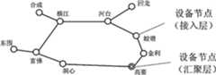
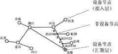
图3a是肇庆市局部通讯传送网络映射到光路层的拓扑结构示意图,图3b是肇庆市局部通讯传送网络映射到线路层的拓扑结构示意图;其中设备节点用空心圆圈表示、非设备节点用实心黑点表示、汇聚节点用双层的圆圈表示;Figure 3a is a schematic diagram of the topological structure of Zhaoqing's local communication transmission network mapped to the optical path layer, and Figure 3b is a schematic diagram of the topological structure of Zhaoqing's local communication transmission network mapped to the line layer; where equipment nodes are represented by hollow circles, and non-equipment nodes are represented by solid black Points are represented, and sink nodes are represented by double-layer circles;
图4是本实用新型传送网络安全分析系统的结构方框图。Fig. 4 is a structural block diagram of the transmission network security analysis system of the present invention.
具体实施方式Detailed ways
下面结合实施例及附图对本实用新型作进一步详细的描述,但本实用新型的实施方式不限于此。The utility model will be further described in detail below in conjunction with the embodiments and accompanying drawings, but the implementation of the utility model is not limited thereto.
目前广泛应用的光纤传送网络,从业务承载的原理来看,管道、杆路等线路上承载着光缆,光缆中包含纤芯,若干段纤芯跳接组成承载光信号的光路,光路连通传输设备形成传输系统,在传输系统中通过交叉连接的建立及通道、时隙的分配提供各种带宽的电路业务。其中,线路、光缆及光路层面分别确定了传送网络在不同层面上的拓扑结构。At present, the widely used optical fiber transmission network, from the perspective of the principle of service bearing, the optical cable is carried on the pipeline, the pole road and other lines. A transmission system is formed in which circuit services of various bandwidths are provided through the establishment of cross-connections and the allocation of channels and time slots. Among them, the line, optical cable and optical path levels respectively determine the topology structure of the transmission network at different levels.
首先利用图论的方法对上述拓扑结构进行安全分析:First, use the method of graph theory to analyze the security of the above topology:
第一步,用节点、设备、线路、光缆、光路、子线路和子光缆来描述传送网络的拓扑结构,其基本关系为:节点包括设备节点和非设备节点,设备安装在设备节点内,线路起点终点都属于节点,线路上承载光缆,光缆起点终点也都属于节点,光缆上承载光路,光路起点终点与设备连接。其中,根据线路上的分支点将线路拆分为若干段子线路,根据光缆上的分纤点,将光缆拆分为若干段子光缆,使得子线路、子光缆与光路具有相同的特点:分别在线路、光缆、光路层面均为最小的拓扑单元,最小的拓扑单元是由两个端点及连接这两个端点的线组成,线上没有任何分支点;任意两个最小的拓扑单元可相互连接,但不会相互交叉。由此,子线路成为本实用新型公开的分析方法中的最小单元,将线路、光缆和光路的关系进行转换,可用有序的子线路集来描述每一段线路、光缆和光路,同理也可用有序的子光缆集来描述每一段光缆和光路,则得到的传送网络的拓扑结构描述体系示意图如图1所示,描述体系中各部分数据应具备的最基本的属性如表1所示。In the first step, the topology of the transmission network is described by nodes, equipment, lines, optical cables, optical paths, sub-lines and sub-optical cables. The basic relationship is: nodes include equipment nodes and non-equipment nodes, equipment is installed in The end point belongs to the node, the optical cable is carried on the line, the starting point and the end point of the optical cable also belong to the node, the optical cable carries the optical path, and the starting point and the end point of the optical path are connected with the equipment. Among them, the line is split into several sections of sub-lines according to the branch point on the line, and the optical cable is split into several sections of sub-optical cables according to the splitting points on the optical cable, so that the sub-lines, sub-optical cables and optical paths have the same characteristics: respectively in the line , optical cable, and optical path are the smallest topological units. The smallest topological unit is composed of two endpoints and a line connecting the two endpoints. There is no branch point on the line; any two smallest topological units can be connected to each other, but will not cross each other. Thus, the sub-circuit becomes the smallest unit in the analysis method disclosed in the utility model, and the relationship between the circuit, optical cable and optical path is converted, and an ordered sub-circuit set can be used to describe each section of circuit, optical cable and optical path, and the same reason can also be used An ordered set of sub-cables is used to describe each section of optical cable and optical path. The schematic diagram of the topology description system of the transmission network obtained is shown in Figure 1. The most basic attributes of each part of the data in the description system are shown in Table 1.
表1Table 1

第二步,用图论模型来表示传送网络的拓扑结构,令图集合Gp=(V,E),其中顶点集合V={v1,v2,…,vn}用来表示传送网络拓扑结构中的节点或设备,边集合E={e1,e2,…,em}∈V×V用来表示传送网络拓扑结构中的光路、子光缆或子线路;邻接矩阵D用来表示顶点v之间的连接关系、关联矩阵A来表示顶点v和边e之间的连接关系:The second step is to use a graph theory model to represent the topology of the transmission network, let the graph set Gp=(V, E), where the vertex set V={v1 , v2 ,...,vn } is used to represent the topology of the transmission network For nodes or devices in the structure, the edge set E={e1 , e2 ,...,em }∈V×V is used to represent the optical path, sub-cable or sub-line in the topology of the transport network; the adjacency matrix D is used to represent The connection relationship between the vertex v and the association matrix A to represent the connection relationship between the vertex v and the edge e:


这样,子线路、子光缆与光路所组成的顶点和边的集合,分别确定了线路层、光缆层和光路层的网络拓扑结构,线路、光缆、光路这三种网络拓扑结构就可以用上述图论模型来表示。In this way, the set of vertices and edges composed of sub-lines, sub-cables, and optical paths respectively determine the network topology of the line layer, optical cable layer, and optical path layer. On the model to represent.
第三步,对上述用图论模型来表示的网络拓扑结构,进行拓扑结构安全分析(包括结构指标分析、光路路由分析、构件失效分析和/或备用路由分析,具体分析的内容如表2所示)。The third step is to perform topology security analysis (including structural index analysis, optical path routing analysis, component failure analysis and/or backup routing analysis) on the above-mentioned network topology represented by the graph theory model. The specific analysis content is shown in Table 2. Show).
表2Table 2
从光路层看,传送网络由光路和设备组成,在该层次,可进行逻辑成环指标分析,如双归接入环数、单归接入环数、接入链数、逻辑成环率、环上接入点数等均属于逻辑成环指标;可进行光路或设备失效时对网络的影响情况分析;可计算设备间存在的可能连通的路由情况,也即业务备用路由分析,主用路由中断时,电路业务可利用备用路由通过自动倒换或手工配置的方式恢复正常。From the perspective of the optical path layer, the transmission network is composed of optical paths and devices. At this layer, logical loop formation indicators can be analyzed, such as the number of dual-homing access rings, the number of single-homing access rings, the number of access links, the logical loop formation rate, The number of access points on the ring is a logical ring formation index; it can analyze the impact on the network when the optical path or equipment fails; it can calculate the possible connected routes between devices, that is, the analysis of business backup routes and the interruption of the main route , the circuit service can be restored to normal through automatic switching or manual configuration by using the backup route.
将光路层中的光路用子光缆的有序集合来表示,设备用其所属节点来表示,则得到映射到光缆层的传送网络,它由子光缆和节点组成,它是全网子光缆和节点组成的拓扑结构的子集。在该层次,可进行子光缆失效时对网络的影响情况分析;可计算节点间通过子光缆段可能连通的路由情况,也即光路备用路由分析,连通的光缆段为设备间的光路提供可能存在的备用路由,光路备用路由是应急跳纤、OLP光开关倒换整治等工作的基础。The optical path in the optical path layer is represented by an ordered set of sub-cables, and the equipment is represented by its own node, then the transmission network mapped to the optical cable layer is obtained, which is composed of sub-cables and nodes, which is composed of sub-cables and nodes of the whole network A subset of the topology. At this level, it is possible to analyze the impact on the network when the sub-cable fails; it is possible to calculate the routes that may be connected between nodes through the sub-cable section, that is, the analysis of the backup route of the optical path. The connected optical cable section provides possible existence for the optical path between devices. The backup route of the optical path is the basis for emergency fiber jumping, OLP optical switch switching and rectification.
将光路层中的光路用子线路的有序集合来表示,设备用其所属节点来表示,则得到映射到线路层的传送网络,也即从实际物理路由层面看到的传送网络,它由子线路和节点组成,它是全网子线路和节点组成的拓扑结构的子集。在该层次,可进行物理成环、安全节点比例指标分析,如物理成环率、一级安全节点比例、二级安全节点比例等均属于物理成环指标;可通过分析进出某节点的光路所经过的实际物理路由是否重叠来识别单节点隐患;可结合节点的经纬度信息对传送网络拓扑结构从光路层面向线路层面的退化情况进行直观呈现;可进行子线路或节点失效时对网络的影响情况分析;可计算节点间通过子线路段可能连通的路由情况,也即光缆备用路由分析,光缆备用路由是应急光缆布放、光缆工程规划等工作的基础。The optical path in the optical path layer is represented by an ordered set of sub-lines, and the equipment is represented by its own node, then the transmission network mapped to the line layer is obtained, that is, the transmission network seen from the actual physical routing level, which consists of sub-lines It is composed of sub-lines and nodes in the whole network, which is a subset of the topology structure composed of sub-lines and nodes in the whole network. At this level, physical ring formation and security node ratio indicators can be analyzed. For example, the physical loop formation rate, the proportion of first-level security nodes, and the proportion of second-level security nodes are all physical loop formation indicators; Whether the actual physical route passed is overlapping to identify hidden dangers of a single node; it can combine the latitude and longitude information of nodes to visually present the degradation of the transmission network topology from the optical path level to the line level; it can analyze the impact on the network when sub-lines or nodes fail Analysis; it can calculate the possible connection routes between nodes through sub-line segments, that is, the analysis of optical cable backup routes. The optical cable backup routes are the basis for emergency optical cable deployment and optical cable engineering planning.
对所述用图论模型表示的传送网络拓扑结构进行结构指标分析、光路路由分析、构件失效分析和/或备用路由分析的具体内容及方法如下:The specific content and method of performing structural index analysis, optical path routing analysis, component failure analysis and/or backup routing analysis on the transport network topology represented by the graph theory model are as follows:
(1)结构指标分析(1) Analysis of structural indicators
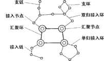
映射到光路层面的传送网络拓扑结构,也就是我们常称的逻辑组网结构,以较为复杂的接入网为例,其典型的逻辑组网结构如图2所示,由汇聚环、双归接入环、单归接入环、接入链、支环、支链等传输系统组成。The topology of the transmission network mapped to the optical path level is what we often call the logical networking structure. Taking a more complex access network as an example, its typical logical networking structure is shown in Figure 2. It consists of aggregation rings, dual-homing Access ring, single-homing access ring, access chain, branch ring, branch chain and other transmission systems.
该结构与图论模型中描述的光路网络拓扑结构是一致的,利用图论中通用的网络组件识别方法可计算与逻辑组网结构相关的指标.网络组件识别的思路如下:在一个网络拓扑结构中,与某节点所关联的边的数目,称为该节点的度,首先标记出所有度大于2的节点,这就得到了网络中的分支节点(称为关键点),它其实包括汇聚分支节点和接入分支节点.然后将单连通节点(即度为1的节点)进行递归删除,直到该网络不再包含这种节点,则被删除的节点的集合就是网络中链型结构的全体,由汇聚分支节点引出的链型结构称为接入链,由接入分支节点引出的链型结构称为支链.删除链型结构所得的网络为封闭网络(即只要非空,则必包含环路的网络),对封闭网络采用一定的寻环策略可找到各环路,从封闭网络中与某关键点(先处理接入分支节点,再处理汇聚分支节点)相邻的某非关键点开始,标记并删除该非关键点,网络将会产生新的单连通节点,递归删除这些节点,直到网络不再包含单连通节点而成为封闭网络,则被删除的节点的集合就是网络中的某一环型结构,接入分支节点引出的环型结构称为支环,汇聚分支节点引出的环型结构称为接入环,若递归删除的过程终止于原来的关键点,则该环型结构为单归环,否则为双归环.选择另外一个关键点,如此循环进行递归删除,即可分离出包含在网络中的各种环型结构,其中由汇聚节点组成的环路即为汇聚环.This structure is consistent with the optical path network topology described in the graph theory model, and the indicators related to the logical network structure can be calculated by using the general network component identification method in graph theory. The idea of network component identification is as follows: in a network topology In , the number of edges associated with a node is called the degree of the node. First, all nodes with a degree greater than 2 are marked, so that the branch nodes (called key points) in the network are obtained, which actually include the convergent branch Nodes and access branch nodes. Then recursively delete simply connected nodes (ie, nodes with a degree of 1) until the network no longer contains such nodes, then the set of deleted nodes is the entirety of the chain structure in the network. The chain structure derived from the converging branch nodes is called an access chain, and the chain structure derived from the access branch nodes is called a branch chain. The network obtained by deleting the chain structure is a closed network (that is, as long as it is not empty, it must contain a ring Each loop can be found by using a certain ring-finding strategy for the closed network, starting from a non-key point adjacent to a key point in the closed network (first process the access branch node, and then process the convergence branch node) , mark and delete the non-key point, the network will generate new singly connected nodes, delete these nodes recursively, until the network no longer contains singly connected nodes and becomes a closed network, then the set of deleted nodes is a certain Ring structure, the ring structure derived from the access branch node is called a branch ring, and the ring structure derived from the convergent branch node is called an access ring. If the recursive deletion process ends at the original key point, the ring structure is Single-homing ring, otherwise it is a double-homing ring. Select another key point and perform recursive deletion in this way to separate various ring structures contained in the network. Among them, the ring composed of sink nodes is the sink ring.
通过以上方法可实现双归环数、单归环数、接入链数、支环数、支链数、接入点成环率、环上接入点数、单汇聚点最大接入链数、接入链最大节点数和末梢最大节点数等逻辑成环指标的分析,而SDH接入点成环率、VIP节点成环率、末梢最大基站节点数等指标其实是上述指标的子集,可通过相同的方法进行分析。Through the above methods, the number of double-homing rings, the number of single-homing rings, the number of access chains, the number of branch rings, the number of branch chains, the rate of access points forming rings, the number of access points on the ring, the maximum number of access links of a single convergence point, The analysis of logical looping indicators such as the maximum number of nodes in the access chain and the maximum number of nodes at the end, while the indicators such as the ringing rate of SDH access points, the ringing rate of VIP nodes, and the maximum number of base station nodes at the end are actually a subset of the above indicators, which can be Analyzed by the same method.
至于物理成环率、一级安全节点比例、二级安全节点比例等物理成环指标,则需将传送网络映射到线路层进行分析。理想状态下,当每段光路所经过的线路都没有重叠时,光路层的逻辑组网结构映射为线路层的物理组网结构后拓扑结构不会发生变化,物理成环率指标也会与逻辑成环率指标一致。而在一般情况下,对于某个逻辑成环的传输系统来说,全环光路所经过的实际路由会有若干重叠的地方,这时候逻辑组网结构向物理组网结构转化则是一个拓扑结构退化的过程,“环”将全部或局部退化成“链”。以肇庆市局部通讯传送网络为例,图3a代表该市局部通讯传送网络映射到光路层的拓扑结构示意图,图3b是该市局部通讯传送网络映射到线路层的拓扑结构示意图,网络结构从光路层映射到线路层后,环型结构局部退化成链型结构。在线路层的物理组网结构下,可通过分析光路的路由重叠情况来判断物理成环情况,计算出物理成环率指标。而安全节点比例也可以在物理组网结构基础上进行计算,在图3b所表示的物理组网结构中(其中设备节点用空心圆圈表示、非设备节点用实心黑点表示、汇聚节点用双层的圆圈表示),包括了“环”以及从环上节点引出的“链”,环上节点则包括了设备节点和非设备节点(如线路分支点、光缆分纤点),一级安全节点应是属于以下情况之一的点的集合:环上的设备节点、环上非设备节点引出的第一条链上的第一个设备节点、汇聚节点直接引出的链上的第一个设备节点;二级安全节点的集合应在一级安全节点集合的基础上增加以下情况:环上设备节点引出的链上的第一个设备节点、环上非设备节点引出的第二条链上的第一个设备节点或者第一条链上的第二个设备节点(二者选一)、汇聚节点直接引出的链上的第二个设备节点。以此类推可计算出各级安全节点比例指标。As for physical loop formation indicators such as the physical loop formation rate, the proportion of primary security nodes, and the proportion of secondary security nodes, it is necessary to map the transmission network to the line layer for analysis. Ideally, when the lines passed by each optical path do not overlap, the topology structure will not change after the logical networking structure of the optical path layer is mapped to the physical networking structure of the line layer, and the physical loop rate index will also be consistent with the logical networking structure. The ring formation rate indicators are consistent. In general, for a transmission system that forms a logical ring, the actual routes passed by the full-ring optical path will have some overlapping places. At this time, the transformation from the logical network structure to the physical network structure is a topology structure. In the process of degeneration, the "ring" will degenerate into a "chain" in whole or in part. Taking the local communication transmission network of Zhaoqing City as an example, Fig. 3a represents the topological structure map of the local communication transmission network of the city to the optical path layer, and Fig. 3b is a schematic diagram of the topology structure mapping of the local communication transmission network of the city to the line layer. After the layer is mapped to the line layer, the ring structure partially degenerates into a chain structure. Under the physical network structure of the line layer, the physical loop formation can be judged by analyzing the routing overlap of the optical path, and the physical loop formation rate index can be calculated. The proportion of secure nodes can also be calculated on the basis of the physical network structure. In the physical network structure shown in Figure 3b (the device nodes are represented by hollow circles, the non-device nodes are represented by solid black dots, and the sink nodes are represented by double-layer ), including the "ring" and the "chain" derived from the nodes on the ring, the nodes on the ring include equipment nodes and non-equipment nodes (such as line branch points, optical fiber splitting points), and the first-level security nodes should be It is a collection of points belonging to one of the following situations: device nodes on the ring, the first device node on the first chain derived from non-device nodes on the ring, and the first device node on the chain directly derived from the sink node; The set of secondary security nodes should add the following conditions on the basis of the set of primary security nodes: the first device node on the chain derived from the device node on the ring, the first device node on the second chain derived from the non-device node on the ring The first device node or the second device node on the first chain (choose one of the two), the second device node on the chain directly derived from the sink node. By analogy, the proportion indicators of security nodes at all levels can be calculated.
(2)光路路由分析(2) Optical path routing analysis
光路路由分析,也就是对传输系统中各光路所经过的实际物理路由进行分析.以图3a代表的逻辑组网结构为例,从汇聚节点高要出发,按顺序经过金利、蛟塘、河台、横江、富佛、洞心后回到高要,组成一个环,而河台、横江、富佛分别带出一条链.映射到线路层的物理组网结构出现了一些变化,成为图3b所示结构,原因是存在以下几点实际情况:洞心没有直接通达高要的光缆,横江才有直接通达高要的光缆,因而洞心-高要的光路是通过三条光缆经由横江、富佛节点跳接而成的;高要-河台的线路由路由分支点(高河#20、高河#80)和光缆分纤点(高河#25、高河#80)分成4段子线路(如图3b中1、2、3、4所示),高要-河台的光缆在高河#25位置分纤引出光缆并在高河#20位置引至金利节点,在高河#80位置分纤并直接引至蛟塘节点.Optical path routing analysis, that is, analyzing the actual physical routing of each optical path in the transmission system. Taking the logical networking structure represented by Figure 3a as an example, starting from the high point of the aggregation node, passing through Jinli, Jiaotang, and Hetai in sequence , Hengjiang, Fufo, and Dongxin returned to Gaoyao to form a ring, while Hetai, Hengjiang, and Fufo brought out a chain respectively. Some changes occurred in the physical network structure mapped to the line layer, which became the link shown in Figure 3b. The reason is that there are the following actual conditions: there is no optical fiber cable directly connected to Gaoyao in the center of the cave, and there is a fiber optic cable directly connected to Gaoyao in Hengjiang, so the optical path from the center of the cave to Gaoyao is through three optical cables via Hengjiang and Fufo nodes Jump-connected; the Gaoyao-Hetai line is divided into 4 sections of sub-lines by routing branch points (Gaohe #20, Gaohe #80) and fiber optic cable splitting points (Gaohe #25, Gaohe #80) (as shown in Figure 3b, 1 , 2, 3, and 4), the optical cable of Gaoyao-Hetai is split at Gaohe #25 and led to the Jinli node at Gaohe #20, and the fiber is split at Gaohe #80 and directly led to Jiaotang node.
在线路层面,是用子线路和节点来描述光路及网络结构的,洞心-高要的光路描述为“洞心《富佛-洞心子线路》富佛《横江-富佛子线路》横江《高要-横江子线路》高要”,很明显,对于该段光路而言,是经过横江、富佛两个节点进行跳纤的,光路的跳纤情况分析与电路的跳线情况分析在方法上其实是一样的。整个传输系统主环的光路描述即为各段光路的有序集合,为“高要《高要-河台子线路1》高河#20《高要-河台子线路2》高河#25《高要-河台子线路2》高河#20《金利接入子线路》金利《金利接入子线路》高河#20《高要-河台子线路2》高河#25《高要-河台子线路3》高河#80《蛟塘接入子线路》蛟塘《蛟塘接入子线路》高河#80《高要-河台子线路4》河台《河台-横江子线路》横江《横江-富佛子线路》富佛《富佛-洞心子线路》洞心《富佛-洞心子线路》富佛《横江-富佛子线路》横江《高要-横江子线路》高要”,从图3b中可以非常方便的识别出单节点隐患情况(在全环的光路路由描述中,若与某设备节点相接的两个方向的子线路是相同的,则该节点存在单节点隐患):与金利、蛟塘、洞心这三个设备节点相接的子线路分别是金利接入子线路、蛟塘接入子线路、富佛-洞心子线路,则金利、蛟塘、洞心进出局光路同路由,存在单节点隐患。At the line level, sub-lines and nodes are used to describe the optical path and network structure. The optical path of Dongxin-Gaoyao is described as "Dongxin" Fufo-Dongxinziline"Fufo"Hengjiang-Fufoziline"Hengjiang" Gaoyao-Hengjiang sub-line "Gaoyao", it is obvious that for this section of the optical path, fiber jumping is performed through the two nodes of Hengjiang and Fufo. It is actually the same. The optical path description of the main ring of the entire transmission system is an ordered collection of optical paths of each section, which is "Gaoyao "Gaoyao-Hetaizi Line 1" Gaohe #20 "Gaoyao-
(3)构件失效分析(3) Component failure analysis
构件指组成网络的各种元件,在本实用新型公开的方法中主要构件有线路、子线路、光缆、子光缆、光路、节点和设备,构件的失效分析基于描述体系中各构件的关联关系。由于光缆经过某段线路时不一定完全从起点至终点贯穿全段线路,光路经过某段光缆时也不一定完全从起点至终点贯穿全段光缆,所以某线路或某光缆在不同的位置点发生故障时对网络的影响情况是不一样的,但将线路和光缆进行拆分后,子线路、子光缆与光路则分别在线路、光缆、光路层面为最小的拓扑单元,同一子线路、子光缆或光路内不同的位置点发生故障时对网络的影响情况是相同的,因此我们进行构件失效分析时选择分别对子线路、子光缆、光路以及节点、设备失效进行分析,而整段线路或光缆失效时,其影响可根据其所包含的子线路或子光缆失效影响情况而得出。Components refer to various elements that make up the network. In the method disclosed by the utility model, the main components include lines, sub-lines, optical cables, sub-optical cables, optical paths, nodes and equipment. The failure analysis of components is based on the relationship between components in the description system. Since the optical cable does not necessarily completely run through the entire section of the line from the starting point to the end point when passing through a certain section of the line, and the optical path does not necessarily completely run through the entire section of the optical cable from the starting point to the end point when passing through a certain section of the optical cable, so a certain line or a certain optical cable occurs at different points. The impact on the network is different when a fault occurs, but after splitting the line and optical cable, the sub-line, sub-optical cable and optical path are the smallest topological units at the line, optical cable, and optical path levels respectively. The same sub-line, sub-optical cable The impact on the network is the same when failures occur at different points in the optical path, so we choose to analyze the failure of sub-lines, sub-cables, optical paths, nodes, and equipment when performing component failure analysis, while the entire line or optical cable When it fails, its impact can be obtained according to the failure impact of the sub-circuits or sub-cables it contains.
子线路失效,其原因可能为管道塌方、电杆倒塌等,其影响为在该子线路上承载的全部子光缆失效;子光缆失效,其原因可能为子线路失效、偷盗破坏、雷击损坏等,其影响为该子光缆上承载的全部光路失效;节点失效,其原因可能为洪水、山火、雷击等自然灾害破坏等,其影响为节点内所有设备失效,与节点相连的所有子线路和子光缆失效.光路失效,其原因可能为子光缆失效、跳纤松脱、枪击损坏等;设备失效,其原因可能为节点失效、设备故障、节点掉电等,光路和节点失效是构件失效最终导致的结果,其影响是直接导致网络组网结构发生变化,并可能导致业务受影响.在光路或节点失效时,描述传送网络拓扑结构的图论模型中的邻接矩阵D和关联矩阵A中的元素数值将发生变化,也即点与点或点与边的连接关系有所改变,利用上述的结构指标分析方法可同步计算出结构指标变化情况.而且,可能同时存在的情况是,因光路或节点失效,导致若干接入节点与汇聚节点的所有光路路由(包括备用路由)中断,该部分接入节点成为图论模型中的孤立点,孤立点对应的传输设备上的业务也将同时中断.这就是构件失效时对传送网络拓扑结构及业务影响情况分析.The failure of the sub-line may be due to the collapse of the pipeline, the collapse of the electric pole, etc., and the impact is the failure of all the sub-optical cables carried on the sub-line; the failure of the sub-optical cable may be due to the failure of the sub-line, theft damage, lightning damage, etc. The impact is the failure of all the optical paths carried on the sub-cable; the failure of the node may be caused by natural disasters such as floods, wildfires, and lightning strikes, etc. The impact is that all equipment in the node fails, and all sub-lines and sub-optical cables connected to the node Failure. The failure of the optical path may be caused by sub-cable failure, loose fiber jumper, gunshot damage, etc.; the cause of equipment failure may be node failure, equipment failure, node power failure, etc. The failure of the optical path and node is ultimately caused by the failure of the component As a result, its impact will directly lead to changes in the network structure, and may lead to business impact. When the optical path or node fails, the adjacency matrix D and the element value in the correlation matrix A in the graph theory model describing the transport network topology Changes will occur, that is, the connection relationship between points and points or between points and edges will be changed. Using the above-mentioned structural index analysis method, the change of structural index can be calculated synchronously. Moreover, the situation that may exist at the same time is that due to the failure of the optical path or node , resulting in the interruption of all optical routes (including backup routes) between several access nodes and sink nodes, and these access nodes become isolated points in the graph theory model, and the services on the transmission equipment corresponding to the isolated points will also be interrupted at the same time. This is Analysis of the impact on transport network topology and services when components fail.
(4)备用路由分析(4) Backup route analysis
不同层面的网络拓扑结构下,备用路由的定义和应用是不同的,光路层面的备用路由是设备间存在的可能连通的路由情况,也即业务备用路由,应用于电路业务路由保护等情况;光缆层面的备用路由是节点间通过子光缆段可能连通的路由情况,也即光路备用路由,应用于应急跳纤、OLP光开关保护等情况;线路层面的备用路由是节点间通过子线路段可能连通的路由情况,也即光缆备用路由,应用于应急光缆布放、光缆工程规划等情况。但备用路由的分析方法是相同的,因为用来描述线路、光缆、光路网络拓扑结构的图论模型是相同的,不同的只是模型中的顶点和边所表示的网络实体,以及确定具体结构关系的邻接矩阵D和关联矩阵A中的元素的具体数值。Under different network topology structures, the definition and application of backup routes are different. The backup route at the optical path level refers to the routing situation that may be connected between devices, that is, the service backup route, which is applied to circuit service route protection and other situations; The backup route at the layer level is the routing situation that the nodes may be connected through the sub-cable segment, that is, the optical path backup route, which is used in emergency fiber jumping, OLP optical switch protection, etc.; the backup route at the line level is the possible connection between nodes through the sub-line segment The routing situation of the optical cable, that is, the optical cable backup route, is applied to emergency optical cable deployment, optical cable engineering planning, etc. However, the analysis methods for alternate routes are the same, because the graph theory models used to describe the network topology of lines, optical cables, and optical paths are the same, and the only difference is the network entities represented by the vertices and edges in the model, as well as the determination of specific structural relationships The specific values of the elements in the adjacency matrix D and the incidence matrix A of .
计算任意两节点间存在的路由情况,并计算路由的长度,剔除路由长度大于预设值(由传输设备光接口的发光功率、接收灵敏度及线路平均衰耗确定,一般可取值为100千米)的不可用路由,则可得到各层次中可用的备用路由,而节点间的路由情况可通过矩阵的变换运算得出,方法如下:对于一个具有n个节点的网络拓扑结构,建立邻接矩阵M=[mij]n×n,mij为该矩阵中的元素,代表从i节点到j节点的连接关系(其中i,j=1,2,…,n),其实该邻接矩阵M与上文提到的邻接矩阵D基本上是一样的。矩阵M中的n×n个元素mij的初始表达式按照如下定义得到:当节点i到j方向无直连链路时(包括i=j时),mij=0;当节点i到j方向有直连链路Xij时,mij=Xij;当节点i到j方向存在多条并联直连链路Xij1,Xij2,...,Xijy时,mij=Xij1+Xij2+…+Xijy。Calculate the routing situation between any two nodes, and calculate the length of the route, and exclude the route length greater than the preset value (determined by the luminous power, receiving sensitivity and average line attenuation of the optical interface of the transmission equipment, generally the value is 100 kilometers ), the available alternate routes in each level can be obtained, and the routing situation between nodes can be obtained by matrix transformation operation, the method is as follows: for a network topology structure with n nodes, establish an adjacency matrix M =[mij ]n×n , mij is the element in the matrix, representing the connection relationship from node i to node j (where i, j=1, 2,..., n), in fact, the adjacency matrix M and the above The adjacency matrix D mentioned in the text is basically the same. The initial expression of n×n elements mij in the matrix M is obtained according to the following definition: when there is no direct link in the direction from node i to j (including when i=j), mij =0; when node i to j When there are direct links Xij in the direction, mij =Xij ; when there are multiple parallel direct links Xij1 , Xij2 ,...,Xijy in the direction from node i to j, mij =Xij1 + Xij2 +…+Xijy .
每次进行变换运算,都指定邻接矩阵中的某一行作为参考,并且该行必须是以前没被指定过的。根据指定的参考行对矩阵中其它行所有元素进行变换运算,而参考行中各元素保持不变。每次矩阵变换运算所需遵循的规则为:假设指定参考行为k,对矩阵中其它行所有元素进行变换,运算公式为:Every time a transformation operation is performed, a certain row in the adjacency matrix is specified as a reference, and the row must not be specified before. Perform transformation operations on all elements in other rows of the matrix according to the specified reference row, while the elements in the reference row remain unchanged. The rules to be followed for each matrix transformation operation are: assuming that the reference row k is specified, all elements in other rows in the matrix are transformed, and the operation formula is:
m′ij=mikmkj+mijm′ij =mik mkj +mij
其中,mik,mkj,mij为变换前矩阵中的元素,m′ij为变换后矩阵中第i行第j列对应的元素。上式是按照逻辑代数运算规则计算的,并且在矩阵变换过程中要遵循逻辑化简原则,即在变换过程中必须利用逻辑公式及蕴含运算规则简化元素m′ij,使之始终为最简的“与或”逻辑表达式。对于有n个节点的网络,需要按照相同的方法做n次矩阵变换。此时,矩阵中每一个元素位置上的“与或”逻辑表达形式,表示的就是行标号和列标号代表的节点间全部可能路由。式中每一个逻辑乘积项就是行列标号所示意的节点之间一条要寻找的路由,所有逻辑乘积项的集合就是行列标号所示意的节点之间要寻找的全部路由。Among them, mik , mkj , mij are the elements in the matrix before transformation, and m′ij is the element corresponding to row i and column j in the matrix after transformation. The above formula is calculated according to the logic algebra operation rules, and the logic simplification principle must be followed in the process of matrix transformation, that is, the logic formula and implication operation rules must be used to simplify the element m′ij during the transformation process, so that it is always the simplest "AND OR" logical expression. For a network with n nodes, n matrix transformations need to be performed in the same way. At this time, the logical expression form of "and or" on the position of each element in the matrix represents all possible routes between nodes represented by row labels and column labels. Each logical product item in the formula is a route to be found between the nodes indicated by the row and column labels, and the set of all logical product items is all the routes to be found between the nodes indicated by the row and column labels.
对所述用图论模型表示的传送网络拓扑结构进行结构指标分析、光路路由分析、构件失效分析和/或备用路由分析,均是由本实用新型的系统实现的:该系统利用数据库控制基础数据的规范性和关联性,利用软件设计实现对图论数学模型及矩阵运算的自动处理,通过GPS定位及视频呈现技术将网络情况生动展示,其包括:用于将传送网络基础数据用图论模型来描述及备份保存数据并提供更新和查询功能的数据管理模块;用于对存储在数据管理模块中的传送网络的各项数据进行拓扑结构安全分析的网络分析模块;用于将数据管理模块和网络分析模块的处理过程数据和结果数据及信息实时呈现的网络呈现模块.所述系统结构方框图如图4所示:所述数据管理模块包括:用于将传送网络基础数据用图论模型来描述并备份保存相关数据的网络数据备份模块;用于调用网络数据备份模块中的数据以供查询的网络数据查询模块;用于调用网络数据备份模块中的数据,更新后将数据存入网络数据备份模块的网络数据更新模块.所述网络分析模块包括:用于调用数据管理模块中的数据并对其进行逻辑成环指标和物理成环指标分析的结构指标分析模块;用于调用数据管理模块中的数据并对其进行单节点隐患识别的光路路由分析模块;用于调用数据管理模块中的数据并对其进行光路失效、设备失效、子光缆失效、子线路失效和节点失效分析的构件失效分析模块;用于调用数据管理模块中的数据并对其进行业务备用路由、光路备用路由和光缆备用路由分析的备用路由分析模块.所述网络呈现模块包括:用于将网络分析模块处理得到的物理节点实时呈现的物理节点呈现模块;用于将网络分析模块处理得到的物理路由实时呈现的物理路由呈现模块;用于将数据管理模块和网络分析模块处理得到的信息进行实时呈现网络信息呈现模块;用于将数据管理模块和网络分析模块处理得到的各种信息以视频方式呈现的网络视频呈现模块.Structural index analysis, optical path routing analysis, component failure analysis and/or backup routing analysis of the transmission network topology represented by the graph theory model are all realized by the system of the present utility model: the system utilizes the database to control the basic data Standardization and relevance, using software design to realize automatic processing of graph theory mathematical models and matrix operations, and vividly displaying network conditions through GPS positioning and video presentation technologies, including: using graph theory models to transmit network basic data A data management module that describes and backs up and saves data and provides update and query functions; a network analysis module for performing topology security analysis on various data of the transmission network stored in the data management module; used for connecting the data management module and the network The processing process data and result data of the analysis module and the network presentation module for real-time presentation of information. The block diagram of the system structure is shown in Figure 4: the data management module includes: used to describe the basic data of the transmission network with a graph theory model and The network data backup module for backing up and saving relevant data; the network data query module for calling the data in the network data backup module for query; used for calling the data in the network data backup module, and storing the data in the network data backup module after updating The network data update module. The network analysis module includes: a structural index analysis module for calling the data in the data management module and analyzing the logical loop index and physical loop index analysis; for calling the data in the data management module Optical path routing analysis module for data and single-node hidden danger identification; component failure analysis module for calling data in the data management module and analyzing optical path failure, equipment failure, sub-cable failure, sub-line failure and node failure ;A backup route analysis module for invoking data in the data management module and analyzing it for business backup routes, optical path backup routes and optical cable backup routes. The network presentation module includes: a physical node for processing the network analysis module The physical node presentation module for real-time presentation; the physical route presentation module for presenting the physical route processed by the network analysis module in real time; the network information presentation module for presenting the information obtained by the data management module and the network analysis module in real time; It is a network video presentation module that presents various information processed by the data management module and the network analysis module in the form of video.
本实用新型的系统的对所述用图论模型表示的传送网络拓扑结构进行结构指标分析、光路路由分析、构件失效分析和/或备用路由分析的工作过程是:传送网络基础数据通过GPS传送到本系统,管理数据模块中的网络数据备份模块对传送网络基础数据用图论模型进行描述并储存,网络数据查询模块通过调用网络数据备份模块中的数据提供查询功能,网络数据更新模块调用网络数据备份模块中的数据根据实际情况进行更新操作后再存入网络数据备份模块,数据管理模块中的各种数据信息可通过网络呈现模块显示出来。对传送网络拓扑结构进行安全分析时,网络分析模块调用管理数据模块中的数据进行结构指标分析、光路路由分析、构件失效分析和/或备用路由分析,网络分析模块处理得到的物理节点由物理节点呈现模块实时呈现;网络分析模块处理得到的物理路由由物理路由呈现模块实时呈现;数据管理模块和网络分析模块处理得到的信息由网络信息呈现模块进行实时呈现;数据管理模块和网络分析模块处理得到的各种信息还可以由网络视频呈现模块以视频方式呈现。The working process of the system of the present utility model for structural index analysis, optical path routing analysis, component failure analysis and/or backup routing analysis of the transmission network topology represented by the graph theory model is: the basic data of the transmission network is transmitted to In this system, the network data backup module in the management data module describes and stores the basic data of the transmission network with a graph theory model, the network data query module provides query functions by calling the data in the network data backup module, and the network data update module calls network data The data in the backup module is updated according to the actual situation and then stored in the network data backup module, and various data information in the data management module can be displayed through the network presentation module. When performing security analysis on the transport network topology, the network analysis module invokes the data in the management data module to perform structural index analysis, optical path routing analysis, component failure analysis and/or backup route analysis, and the physical nodes processed by the network analysis module are divided into physical nodes The presentation module presents in real time; the physical route processed by the network analysis module is presented in real time by the physical route presentation module; the information processed by the data management module and the network analysis module is presented in real time by the network information presentation module; the data management module and the network analysis module process the All kinds of information can also be presented in video by the network video presentation module.
应用上述系统,可加快故障定位和抢通,平均缩短故障处理历时约0.5小时/次,按平均每次故障历时为2小时计算,可提升故障处理效率约25%。对全省折合约50万条2M电路按平均不可用时长占0.005%计算(2M电路日常运维可用率指标为99.990%-100%),故障处理效率的提升可减少全年电路退服时长5.48万(2M×小时)。Applying the above-mentioned system can speed up fault location and emergency response, and shorten the fault processing time by about 0.5 hours per time on average. If the average fault duration is 2 hours per fault, the fault processing efficiency can be improved by about 25%. For the 500,000 2M circuits in the province, the average unavailable time accounts for 0.005% (the daily operation and maintenance availability index of 2M circuits is 99.990%-100%), and the improvement of fault handling efficiency can reduce the annual circuit outage time by 5.48% Ten thousand (2M×hours).
而在社会效益方面,电路退服时长的减少提升了网络可用率,为国家及公众提供了更完善的基础通信保障,网络拓扑结构的进一步优化以及备用路由应急保障体系的完善提升了网络可靠性,特别在发生战争或自然灾害等特殊情况时(比如今年5月份的汶川地震),更高的网络可靠性往往能为最有需要的地方提供可靠的网络信号,为政府指挥应急调度、挽救公众生命和财富创造不可估量的价值。In terms of social benefits, the reduction of the circuit decommissioning time improves the network availability rate and provides a more complete basic communication guarantee for the country and the public. The further optimization of the network topology and the improvement of the backup route emergency protection system improve the network reliability. , especially in special situations such as wars or natural disasters (such as the Wenchuan earthquake in May this year), higher network reliability can often provide reliable network signals for the most needed places, command emergency dispatch for the government, and save the public Life and wealth create immeasurable value.
上述实施例为本实用新型较佳的实施方式,但本实用新型的实施方式并不受上述实施例的限制,任何未背离本实用新型的精神实质与原理下所作的改变、修饰、替代、组合、简化,均应为等效的置换方式,都包含在本实用新型的保护范围之内.The above-mentioned embodiment is a preferred implementation mode of the present utility model, but the implementation mode of the present utility model is not limited by the above-mentioned embodiment, and any changes, modifications, substitutions and combinations made without departing from the spirit and principle of the present utility model , simplification, all should be equivalent replacement methods, and are all included in the protection scope of the present utility model.
Claims (4)
Translated fromChinesePriority Applications (1)
| Application Number | Priority Date | Filing Date | Title |
|---|---|---|---|
| CN2009200593957UCN201467146U (en) | 2009-06-29 | 2009-06-29 | A Transport Network Topology Security Analysis System |
Applications Claiming Priority (1)
| Application Number | Priority Date | Filing Date | Title |
|---|---|---|---|
| CN2009200593957UCN201467146U (en) | 2009-06-29 | 2009-06-29 | A Transport Network Topology Security Analysis System |
Publications (1)
| Publication Number | Publication Date |
|---|---|
| CN201467146Utrue CN201467146U (en) | 2010-05-12 |
Family
ID=42394492
Family Applications (1)
| Application Number | Title | Priority Date | Filing Date |
|---|---|---|---|
| CN2009200593957UExpired - LifetimeCN201467146U (en) | 2009-06-29 | 2009-06-29 | A Transport Network Topology Security Analysis System |
Country Status (1)
| Country | Link |
|---|---|
| CN (1) | CN201467146U (en) |
Cited By (4)
| Publication number | Priority date | Publication date | Assignee | Title |
|---|---|---|---|---|
| CN102117263A (en)* | 2011-03-22 | 2011-07-06 | 无锡永中软件有限公司 | Graph-theory analysis device and graph-theory analysis method based on spreadsheet |
| CN108449141A (en)* | 2018-01-19 | 2018-08-24 | 国网福建省电力有限公司福州供电公司 | A network architecture model construction method based on industrial Ethernet dual-fiber self-healing ring networking mode |
| CN109936484A (en)* | 2017-12-15 | 2019-06-25 | 中国移动通信集团浙江有限公司 | A method and device for identifying network structure risks |
| CN110858777A (en)* | 2018-08-24 | 2020-03-03 | 中国移动通信集团广东有限公司 | Analysis method and equipment for hidden danger of co-routing in transmission network |
- 2009
- 2009-06-29CNCN2009200593957Upatent/CN201467146U/ennot_activeExpired - Lifetime
Cited By (7)
| Publication number | Priority date | Publication date | Assignee | Title |
|---|---|---|---|---|
| CN102117263A (en)* | 2011-03-22 | 2011-07-06 | 无锡永中软件有限公司 | Graph-theory analysis device and graph-theory analysis method based on spreadsheet |
| CN102117263B (en)* | 2011-03-22 | 2016-03-16 | 无锡永中软件有限公司 | Based on the Graph Analysis device and method of electrical form |
| CN109936484A (en)* | 2017-12-15 | 2019-06-25 | 中国移动通信集团浙江有限公司 | A method and device for identifying network structure risks |
| CN109936484B (en)* | 2017-12-15 | 2020-10-13 | 中国移动通信集团浙江有限公司 | Method and device for identifying network structure risk |
| CN108449141A (en)* | 2018-01-19 | 2018-08-24 | 国网福建省电力有限公司福州供电公司 | A network architecture model construction method based on industrial Ethernet dual-fiber self-healing ring networking mode |
| CN110858777A (en)* | 2018-08-24 | 2020-03-03 | 中国移动通信集团广东有限公司 | Analysis method and equipment for hidden danger of co-routing in transmission network |
| CN110858777B (en)* | 2018-08-24 | 2021-04-16 | 中国移动通信集团广东有限公司 | Analysis method and equipment for hidden danger of co-routing in transmission network |
Similar Documents
| Publication | Publication Date | Title |
|---|---|---|
| CN101588518B (en) | Transport network topological structure safety analytical method and implementation system | |
| CN101614781B (en) | Intelligent diagnosis method of radio and television equipment based on spatial rule index | |
| Fan et al. | A modified connectivity link addition strategy to improve the resilience of multiplex networks against attacks | |
| Pant et al. | Vulnerability assessment framework for interdependent critical infrastructures: case-study for Great Britain’s rail network | |
| CN105099547B (en) | A kind of analysis interruption of optical cables influences and realized the method and apparatus that business is switched | |
| Chen et al. | Simulation-based vulnerability assessment in transit systems with cascade failures | |
| CN109344975B (en) | A method and system for checking and optimizing a single point of failure for power communication services | |
| CN110708116B (en) | Optical path management system and method for rapidly positioning and analyzing same route of optical path | |
| CN114172784B (en) | Network fault risk analysis method and device | |
| CN109995565A (en) | Group customer business quality monitoring method, device, equipment and medium | |
| CN108650140A (en) | The automation aided analysis method and system of optical transmission device traffic failure | |
| CN201467146U (en) | A Transport Network Topology Security Analysis System | |
| CN105187255B (en) | Failure analysis methods, fail analysis device and server | |
| CN106982143A (en) | A kind of method of utilization topological realization telecommunications index monitoring | |
| CN110858777A (en) | Analysis method and equipment for hidden danger of co-routing in transmission network | |
| Misra et al. | Estimating extreme event resilience of rail–truck intermodal freight networks: Methods, models, and case study application | |
| CN114338371A (en) | Method for positioning IPRAN network fault based on alarm | |
| CN107548087A (en) | A kind of method and device of warning association analysis | |
| CN114726778B (en) | Service Dedicated Line Activation Method and Server | |
| CN107231187A (en) | A kind of transmission cable fault judgment method, device and terminal | |
| CN106878063A (en) | A kind of method for recovering network topological sum business configuration data from network element | |
| CN109858822A (en) | A kind of electric power in information society emerging system reliability estimation method based on stream association analysis | |
| CN114553680A (en) | Communication underlying network fault rapid positioning auxiliary method and device | |
| Das et al. | A network planning and management tool for mitigating the impact of spatially correlated failures in infrastructure networks | |
| Mosayyebi et al. | Structural Analysis of Iran Railway Network based on Complex Network Theory |
Legal Events
| Date | Code | Title | Description |
|---|---|---|---|
| C14 | Grant of patent or utility model | ||
| GR01 | Patent grant | ||
| CX01 | Expiry of patent term | ||
| CX01 | Expiry of patent term | Granted publication date:20100512 |