CN201440768U - Folding hand-held device - Google Patents
Folding hand-held deviceDownload PDFInfo
- Publication number
- CN201440768U CN201440768UCN2009201663124UCN200920166312UCN201440768UCN 201440768 UCN201440768 UCN 201440768UCN 2009201663124 UCN2009201663124 UCN 2009201663124UCN 200920166312 UCN200920166312 UCN 200920166312UCN 201440768 UCN201440768 UCN 201440768U
- Authority
- CN
- China
- Prior art keywords
- housing
- shell fragment
- curved surface
- flange
- foldable
- Prior art date
- Legal status (The legal status is an assumption and is not a legal conclusion. Google has not performed a legal analysis and makes no representation as to the accuracy of the status listed.)
- Expired - Lifetime
Links
Images


Landscapes
- Casings For Electric Apparatus (AREA)
Abstract
Description
Translated fromChinese技术领域technical field
本实用新型有关一种手持装置,且特别是有关于一种折叠式手持装置。The utility model relates to a hand-held device, in particular to a foldable hand-held device.
背景技术Background technique
随着3C(Computer,Communications and Consumer)产业的发展,有越来越多的人会使用手持装置(handheld device)作为生活中的辅助工具。举例而言,常见的手持装置包含个人数字助理(personal digital assistant;PDA)、移动电话(mobile phone)、智能型手机(smart phone)等,这些手持装置的体积轻巧,携带方便,因此使用的人数越来越多,所需的功能亦越来越广。With the development of 3C (Computer, Communications and Consumer) industry, more and more people will use handheld devices (handheld devices) as auxiliary tools in life. For example, common handheld devices include personal digital assistant (personal digital assistant; PDA), mobile phone (mobile phone), smart phone (smart phone), etc. These handheld devices are light in size and easy to carry, so the number of users There are more and more, and the required functions are also more and more extensive.
为了在有限的空间中提供更多的功能,这些手持装置常常具有可掀合的外壳,如折叠式手机等。现有技术中多使用铰链(hinge)作为转轴机构,但由于铰链仍会占用一定的空间,与手持装置所追求的轻薄设计不符,因此,如何有效地减少折叠式手持装置中转轴所占用的空间,便成为一个相当重要的课题。In order to provide more functions in a limited space, these handheld devices often have a cover that can be folded, such as a foldable mobile phone. In the prior art, hinges are mostly used as the rotating shaft mechanism, but the hinge still occupies a certain space, which is inconsistent with the thin and light design pursued by the handheld device. Therefore, how to effectively reduce the space occupied by the rotating shaft in the folding handheld device , has become a very important topic.
实用新型内容Utility model content
因此本实用新型的目的就是在提供一种不使用铰链的折叠式手持装置,用以节省转轴机构所占用的空间。Therefore, the purpose of the present invention is to provide a foldable handheld device without hinges, so as to save the space occupied by the rotating shaft mechanism.
依照本实用新型一方面,提出一种折叠式手持装置,包含第一壳体、第二壳体、连接第一壳体与第二壳体的连接机构、以及设置于第一壳体上的弹片。第二壳体包含抵靠面与曲面,曲面包含凹槽。弹片的一端与第二壳体接触,弹片包含凸缘,凸缘设置于弹片与第二壳体接触的一端。其中当第二壳体沿着旋转轴向相对于第一壳体旋转时,凸缘与第二壳体保持接触。According to one aspect of the present invention, a foldable hand-held device is proposed, comprising a first housing, a second housing, a connection mechanism connecting the first housing and the second housing, and an elastic piece disposed on the first housing . The second shell includes an abutment surface and a curved surface, and the curved surface includes a groove. One end of the elastic sheet is in contact with the second casing, and the elastic sheet includes a flange, and the flange is arranged at the end of the elastic sheet in contact with the second casing. Wherein when the second housing rotates relative to the first housing along the rotation axis, the flange keeps in contact with the second housing.
当折叠式手持装置处于第一定位位置时,弹片的凸缘与第二壳体的抵靠面接触。当折叠式手持装置处于第二定位位置时,弹片的凸缘与第二壳体的凹槽卡合。连接机构包含转轴,转轴为穿过第二壳体,使第二壳体相对第一壳体旋转。第一壳体包含定位柱,弹片包含定位孔,定位孔为与定位柱卡合。弹片可为垂直于旋转轴向设置。曲面包含两凸出部,凹槽为设置于两凸出部之间。弹片的材料可为弹性材料。When the foldable hand-held device is at the first positioning position, the flange of the elastic piece is in contact with the abutting surface of the second housing. When the foldable handheld device is at the second positioning position, the flange of the elastic piece engages with the groove of the second housing. The connecting mechanism includes a rotating shaft, which passes through the second casing to make the second casing rotate relative to the first casing. The first housing includes a positioning post, and the elastic piece includes a positioning hole, and the positioning hole is engaged with the positioning post. The shrapnel can be arranged perpendicular to the axis of rotation. The curved surface includes two protrusions, and the groove is arranged between the two protrusions. The material of the shrapnel can be elastic material.
本实用新型的另一态样为一种折叠式手持装置,包含第一壳体、具有曲面的第二壳体、以及使第二壳体沿着旋转轴向相对于第一壳体旋转的连接第一壳体与第二壳体的连接机构。折叠式手持装置更包含定位机构,定位机构包含设置于第一壳体的弹片,以及设置于第二壳体的曲面的凹槽。弹片包含有凸缘,凸缘设置于弹片与第二壳体接触的一端。当第二壳体相对于第一壳体旋转至第一定位位置时,弹片为沿着曲面滑动,使凸缘与凹槽卡合。Another aspect of the present invention is a foldable hand-held device, which includes a first housing, a second housing with a curved surface, and a connection that allows the second housing to rotate relative to the first housing along the rotation axis. A connection mechanism between the first shell and the second shell. The foldable handheld device further includes a positioning mechanism, and the positioning mechanism includes an elastic piece disposed on the first housing, and a groove disposed on the curved surface of the second housing. The elastic piece includes a flange, and the flange is arranged at an end of the elastic piece in contact with the second casing. When the second housing rotates to the first positioning position relative to the first housing, the elastic piece slides along the curved surface, so that the flange engages with the groove.
第二壳体包含有与曲面相连的抵靠面,当第二壳体相对于第一壳体旋转至第二定位位置时,弹片可沿着曲面滑动,使凸缘脱离凹槽而与抵靠面接触。连接机构包含转轴,转轴为穿过第二壳体,使第二壳体相对第一壳体旋转。第一壳体包含定位柱,弹片包含定位孔,定位孔为与定位柱卡合。其中弹片可为垂直于旋转轴向设置。曲面包含两凸出部,凹槽为设置于两凸出部之间。弹片的材料可为弹性材料。The second housing includes an abutting surface connected with the curved surface. When the second housing is rotated to the second positioning position relative to the first housing, the shrapnel can slide along the curved surface, so that the flange breaks away from the groove and is in contact with the abutting surface. surface contact. The connecting mechanism includes a rotating shaft, which passes through the second casing to make the second casing rotate relative to the first casing. The first housing includes a positioning post, and the elastic piece includes a positioning hole, and the positioning hole is engaged with the positioning post. The shrapnel can be arranged perpendicular to the axis of rotation. The curved surface includes two protrusions, and the groove is arranged between the two protrusions. The material of the shrapnel can be elastic material.
本实用新型的有益技术效果是:本实用新型中具有曲面的第二壳体可视为凸轮结构,以通过弹片与第二壳体的曲面提供折叠式手持装置开合时所需要的预力,并借助弹片上的凸缘接触第二壳体的抵靠面或是与凹槽卡合时的弹力,使折叠式手持装置定位在第一定位位置与第二定位位置。因此,本实用新型的折叠式手持装置可不使用铰链,从而可节省转轴机构所占用的空间。The beneficial technical effects of the utility model are: the second housing with a curved surface in the utility model can be regarded as a cam structure, so as to provide the required pre-force when the foldable handheld device is opened and closed through the shrapnel and the curved surface of the second housing, And the foldable handheld device is positioned at the first positioning position and the second positioning position by means of the elastic force when the flange on the elastic piece contacts the abutting surface of the second housing or engages with the groove. Therefore, the foldable handheld device of the present invention does not need a hinge, thereby saving the space occupied by the rotating shaft mechanism.
附图说明Description of drawings
为让本实用新型的上述和其它目的、特征、优点能更明显易懂,以下将配合附图对本实用新型的较佳实施例进行详细说明,其中:In order to make the above and other purposes, features and advantages of the present utility model more obvious and understandable, preferred embodiments of the present utility model will be described in detail below in conjunction with the accompanying drawings, wherein:
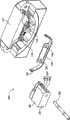
图1是绘示本实用新型的折叠式手持装置一实施例的分解立体图;以及FIG. 1 is an exploded perspective view illustrating an embodiment of a foldable handheld device of the present invention; and
图2A至图2C是分别绘示图1的折叠式手持装置于不同使用状态的实施示意图。FIG. 2A to FIG. 2C are schematic diagrams respectively illustrating the implementation of the foldable handheld device in FIG. 1 in different usage states.
具体实施方式Detailed ways
以下将以附图及详细说明清楚说明本实用新型的精神,任何所属技术领域中具有通常知识者在了解本实用新型的较佳实施例后,当可由本实用新型所教示的技术,加以改变及修饰,其并不脱离本实用新型的精神与范围。The following will clearly illustrate the spirit of the utility model with the accompanying drawings and detailed descriptions. After any person with ordinary knowledge in the technical field understands the preferred embodiments of the utility model, he or she can change and modify the technology taught by the utility model. modifications without departing from the spirit and scope of the present invention.
参照图1,其是绘示本实用新型的折叠式手持装置一实施例的分解立体图。本实用新型提出一种不使用铰链作为转轴机构的折叠式手持装置100,为了更清楚地描述本实用新型的技术特征,折叠式手持装置100中与转动机制无关的元件在此省略,合先叙明。Referring to FIG. 1 , it is an exploded perspective view illustrating an embodiment of a foldable handheld device of the present invention. This utility model proposes a foldable
折叠式手持装置100包含一第一壳体110、一第二壳体120、连接第一壳体110与第二壳体120的一连接机构130、以及设置于第一壳体110上的一弹片140。其中第二壳体120包含一抵靠面122与一曲面124,曲面124上包含一凹槽126。弹片140则包含一凸缘142,凸缘142为设置在弹片140与第二壳体120接触的一端,其中当第二壳体120相对于第一壳体110旋转时,弹片140的凸缘142与第二壳体120保持接触。其中,弹片140的材料可为弹性材料,例如是金属或塑料之类的弹性材料。The foldable
连接机构130包含一转轴,转轴的连接机构130为穿过第二壳体120,使第二壳体120可相对于第一壳体110旋转。第一壳体110包含至少一定位柱112,弹片140则包含至少一定位孔144,定位孔144与定位柱112卡合,以将弹片140固定在第一壳体110上。第二壳体120的抵靠面122与曲面124相连,曲面124包含两凸出部128,凹槽126为设置在两凸出部128之间,其中凸出部128为弧状突起。The
参照图2A至图2C,其是分别绘示图1的折叠式手持装置于不同使用状态的实施示意图。图2A的状态200中,折叠式手持装置100处于第一定位位置,第二壳体120为直立于第一壳体110,此时第二壳体120的抵靠面122与第一壳体110接触,第一壳体110可支撑住与其接触的第二壳体120使得第二壳体120不会向弹片140的方向倾倒。设置于第一壳体110上的弹片140的凸缘142亦与第二壳体120的抵靠面122接触,其中弹片140与第二壳体120的接触位置为第二壳体120接近第一壳体110的一端,即弹片140所施加的弹力为施加在第二壳体120的底部,使第二壳体120在没有外力的时候,不容易向相对于弹片140的另一侧倾倒,如此一来,第二壳体120可相对地直立于第一壳体110,使折叠式手持装置100处于第一定位位置。Referring to FIG. 2A to FIG. 2C , they are respectively schematic diagrams illustrating the implementation of the foldable handheld device in FIG. 1 in different usage states. In the
接着,参照图2B的状态210,此时的使用者可施加外力,以克服弹片140所施加的弹力而推动第二壳体120,使第二壳体120因受力而向外打开,即第二壳体120沿着旋转轴向150相对于第一壳体110转动,其中弹片140为垂直于旋转轴向150设置。由于第二壳体120包含弧形的曲面124,因此,在推开第二壳体120的时候,弹片140可顺着第二壳体120的弧形的曲面124产生摇摆的动作。此时,具有曲面124的第二壳体120可视为凸轮的一部分,弹片140摇摆的幅度可由曲面124的形状控制。Next, referring to the
最后,参照图2C的状态220,此时的第二壳体120沿着旋转轴向150被展开,使折叠式手持装置100处于一第二定位位置,而顺着第二壳体120的曲面124滑动的弹片140上的凸缘142则与第二壳体120上的凹槽126卡合。弹片140的凸缘142为抵住第二壳体120的凹槽126,以限制第二壳体120的位移,使折叠式手持装置100保持在第二定位位置。Finally, referring to the state 220 of FIG. 2C , the
如图2A至图2C所示,第二壳体120可沿着旋转轴向150相对于第一壳体110在第一定位位置与第二定位位置之间转动。第二壳体120相对于第一壳体110的掀合角度约在0度至90度之间。当第二壳体120沿着旋转轴向150相对于第一壳体110转动时,设置于第一壳体110上的弹片140的凸缘142与第二壳体120保持接触,其中当折叠式手持装置100处于第一定位位置时,弹片140上的凸缘142与第二壳体120的抵靠面122接触,接着,使用者可施力于第二壳体120,使弹片140沿着曲面124滑动,使折叠式手持装置100处于第二定位位置时,弹片140上的凸缘142与第二壳体120的凹槽126卡合。使用者可再一次地施力于第二壳体120,使得弹片140上的凸缘142脱离第二壳体120上的凹槽126,而沿着曲面124滑动,使折叠式手持装置100回到第一定位位置。As shown in FIGS. 2A to 2C , the
由上述本实用新型较佳实施例可知,应用本实用新型具有下列优点。本实用新型中具有曲面的第二壳体可视为凸轮结构,以通过弹片与第二壳体的曲面提供折叠式手持装置开合时所需要的预力,并借助弹片上的凸缘接触第二壳体的抵靠面或是与凹槽卡合时的弹力,使折叠式手持装置定位在第一定位位置与第二定位位置。It can be seen from the preferred embodiments of the utility model described above that the application of the utility model has the following advantages. In the utility model, the second housing with a curved surface can be regarded as a cam structure, so as to provide the required pre-force when the folding handheld device is opened and closed through the elastic piece and the curved surface of the second housing, and contact the second housing with the help of the flange on the elastic piece. The abutting surface of the two casings or the elastic force when engaged with the groove makes the foldable handheld device positioned at the first positioning position and the second positioning position.
虽然本实用新型已以较佳实施例揭露如上,然而其并非用以限定本实用新型,任何熟悉此技术者,在不脱离本实用新型的精神和范围内,当可作各种等同的改变或替换,因此本实用新型的保护范围当视后附的本申请权利要求所界定的为准。Although the present utility model has been disclosed as above with preferred embodiments, it is not intended to limit the present utility model. Anyone familiar with this technology can make various equivalent changes or changes without departing from the spirit and scope of the present utility model. Replacement, so the scope of protection of the present utility model shall prevail as defined by the appended claims of the application.
Claims (15)
Priority Applications (1)
| Application Number | Priority Date | Filing Date | Title |
|---|---|---|---|
| CN2009201663124UCN201440768U (en) | 2009-07-20 | 2009-07-20 | Folding hand-held device |
Applications Claiming Priority (1)
| Application Number | Priority Date | Filing Date | Title |
|---|---|---|---|
| CN2009201663124UCN201440768U (en) | 2009-07-20 | 2009-07-20 | Folding hand-held device |
Publications (1)
| Publication Number | Publication Date |
|---|---|
| CN201440768Utrue CN201440768U (en) | 2010-04-21 |
Family
ID=42545422
Family Applications (1)
| Application Number | Title | Priority Date | Filing Date |
|---|---|---|---|
| CN2009201663124UExpired - LifetimeCN201440768U (en) | 2009-07-20 | 2009-07-20 | Folding hand-held device |
Country Status (1)
| Country | Link |
|---|---|
| CN (1) | CN201440768U (en) |
Cited By (2)
| Publication number | Priority date | Publication date | Assignee | Title |
|---|---|---|---|---|
| WO2020024188A1 (en)* | 2018-08-01 | 2020-02-06 | 深圳市柔宇科技有限公司 | Electronic device |
| CN116972063A (en)* | 2021-09-18 | 2023-10-31 | 荣耀终端有限公司 | Folding assembly of electronic equipment and electronic equipment |
- 2009
- 2009-07-20CNCN2009201663124Upatent/CN201440768U/ennot_activeExpired - Lifetime
Cited By (3)
| Publication number | Priority date | Publication date | Assignee | Title |
|---|---|---|---|---|
| WO2020024188A1 (en)* | 2018-08-01 | 2020-02-06 | 深圳市柔宇科技有限公司 | Electronic device |
| CN112640021A (en)* | 2018-08-01 | 2021-04-09 | 深圳市柔宇科技股份有限公司 | Electronic device |
| CN116972063A (en)* | 2021-09-18 | 2023-10-31 | 荣耀终端有限公司 | Folding assembly of electronic equipment and electronic equipment |
Similar Documents
| Publication | Publication Date | Title |
|---|---|---|
| US7836554B2 (en) | Double hinge assembly and electronic device using the same | |
| US7616435B2 (en) | Handheld electronic device having a cover turnable 360 degrees relative to a body thereof | |
| US7821783B2 (en) | Double hinge assembly and electronic device using the same | |
| TWI398209B (en) | Biaxial hinge device and its electronic equipment | |
| US8339777B2 (en) | Portable electronic device with improved pivoting range | |
| TWI683206B (en) | Electronic device | |
| US20240251515A1 (en) | Foldable hinge and electronic device | |
| US8646152B2 (en) | Transversely movable hinge and folding device utilizing the same | |
| TW201328496A (en) | Electronic apparatus and hinge structure thereof | |
| CN201440768U (en) | Folding hand-held device | |
| CN102256462A (en) | Portable electronic system | |
| CN201110311Y (en) | Multi-section torsion pivot structure | |
| US8078236B2 (en) | Rotary cover mechanism for portable electronic devices | |
| CN107155357B (en) | Computing device with rotatable display member | |
| CN203535536U (en) | Electronic device with support structure | |
| CN101646320B (en) | Electronic device and method of use thereof | |
| KR101113712B1 (en) | Free Stop Hinge Modules for Mobile Devices | |
| CN209414378U (en) | Hub and electronic device using it | |
| TWM368242U (en) | Foldable handheld device | |
| CN103163942A (en) | Peripheral device | |
| CN2547073Y (en) | Portable electronic apparatus | |
| US7822445B2 (en) | Hand held apparatus and flip device thereof | |
| CN206257158U (en) | Double-shaft type pivot device | |
| CN201629055U (en) | Electronic book with double display screens | |
| CN219643946U (en) | Electronic equipment support |
Legal Events
| Date | Code | Title | Description |
|---|---|---|---|
| C14 | Grant of patent or utility model | ||
| GR01 | Patent grant | ||
| CX01 | Expiry of patent term | ||
| CX01 | Expiry of patent term | Granted publication date:20100421 |