CN201440227U - Display module, related electronic device and combination of host and display shell - Google Patents
Display module, related electronic device and combination of host and display shellDownload PDFInfo
- Publication number
- CN201440227U CN201440227UCN2009201541697UCN200920154169UCN201440227UCN 201440227 UCN201440227 UCN 201440227UCN 2009201541697 UCN2009201541697 UCN 2009201541697UCN 200920154169 UCN200920154169 UCN 200920154169UCN 201440227 UCN201440227 UCN 201440227U
- Authority
- CN
- China
- Prior art keywords
- display
- electrical connector
- host
- housing
- recessed space
- Prior art date
- Legal status (The legal status is an assumption and is not a legal conclusion. Google has not performed a legal analysis and makes no representation as to the accuracy of the status listed.)
- Expired - Lifetime
Links
- 238000006073displacement reactionMethods0.000claimsdescription2
- 230000004308accommodationEffects0.000claims4
- RYGMFSIKBFXOCR-UHFFFAOYSA-NCopperChemical compound[Cu]RYGMFSIKBFXOCR-UHFFFAOYSA-N0.000description4
- 239000011889copper foilSubstances0.000description4
- 238000000034methodMethods0.000description4
- 230000000694effectsEffects0.000description3
- 239000000463materialSubstances0.000description2
- 238000012545processingMethods0.000description2
- 238000013461designMethods0.000description1
- 238000003780insertionMethods0.000description1
- 230000037431insertionEffects0.000description1
- 238000012423maintenanceMethods0.000description1
- 238000012986modificationMethods0.000description1
- 230000004048modificationEffects0.000description1
- 229920001690polydopaminePolymers0.000description1
Images


Landscapes
- Devices For Indicating Variable Information By Combining Individual Elements (AREA)
Abstract
Description
Translated fromChinese技术领域technical field
本实用新型涉及一种显示器模块、具有该显示器模块的电子装置以及主机与显示器外壳的组合,特别是涉及一种显示面板能藉由插接方式设置在显示器外壳的显示器模块、具有该显示器模块的电子装置以及主机与显示器外壳的组合。The utility model relates to a display module, an electronic device with the display module, and a combination of a host and a display casing, in particular to a display module with a display panel that can be arranged on the display casing by plugging, and a display module with the display module. Combination of electronic device and host with display case.
背景技术Background technique
一般具有显示屏幕的电子装置(例如美国专利US7379292所公开的笔记本型计算机),其显示面板是设置在外壳内并且藉由导线与主机连接。Generally, in an electronic device with a display screen (such as a notebook computer disclosed in US Pat. No. 7,379,292), the display panel is arranged in a casing and connected to a host computer through a wire.
然而,也由于显示面板是藉由导线与主机连接,不仅在组装的过程中需要有拉线及理线的操作而较费时费工,且当显示面板需要由外壳拆离进行维修或替换时,在拆装操作上也较不容易。However, because the display panel is connected to the host by wires, not only the operation of pulling and managing the wires is time-consuming and labor-intensive during the assembly process, but also when the display panel needs to be detached from the casing for maintenance or replacement, the It is also not easy to disassemble and assemble.
实用新型内容Utility model content
因此,本实用新型的目的,即在于提供一种显示面板可轻易由显示器外壳组装及拆离的显示器模块。Therefore, the purpose of the present invention is to provide a display module in which the display panel can be easily assembled and disassembled from the display case.
本实用新型的另一目的,在于提供一种藉由类似于插卡的方式而能将显示面板与显示器外壳组装的显示器模块,藉此减少显示面板与主机之间的理线及拉线问题。Another object of the present invention is to provide a display module capable of assembling the display panel and the display casing in a manner similar to that of a card, thereby reducing the problems of cable management and pulling between the display panel and the host.
本实用新型的再一目的,在于提供一种具有前述显示器模块的电子装置。Another object of the present invention is to provide an electronic device with the aforementioned display module.
本实用新型的又一目的,在于提供一种主机与显示器外壳的组合,该显示器外壳可供一显示面板轻易地组装并且与主机电性连接以及轻易地拆离。Yet another object of the present invention is to provide a combination of a host and a display housing. The display housing can be easily assembled with a display panel and electrically connected to the host and easily detached.
于是,本实用新型的电子装置包含一主机以及一显示器模块。该主机包含一外壳、一设置于该外壳内的电子组件模块以及一设置于该外壳并且外露于该外壳顶面的操作界面。该显示器模块包括一显示器外壳以及一插接单元。该显示器外壳连接该主机的外壳并且形成有一凹陷空间。该插接单元包括一与该主机的电子组件模块电性连接的挠性信号连接件,以及一与该挠性信号连接件电性连接并且外露于该显示器外壳的凹陷空间的第一电性插接件,且该第一电性插接件藉与该挠性信号连接件的连接而具有能相对于该显示器外壳活动的可活动性。该显示面板包括一用以显示影像的面板单元以及一设置于该面板单元并且与该面板单元电性连接的第二电性插接件,该显示面板能藉该第二电性插接件插接于该第一电性插接件而与该主机的电子组件模块电性连接并且容置于该显示器外壳的凹陷空间。Therefore, the electronic device of the present invention includes a host and a display module. The host computer includes a casing, an electronic component module arranged in the casing, and an operation interface arranged in the casing and exposed on the top surface of the casing. The display module includes a display shell and a plug-in unit. The display shell is connected with the shell of the host and forms a recessed space. The plug unit includes a flexible signal connector electrically connected to the electronic component module of the host, and a first electrical plug electrically connected to the flexible signal connector and exposed to the recessed space of the display housing. Connector, and the first electrical connector is movable relative to the display housing through the connection with the flexible signal connector. The display panel includes a panel unit for displaying images and a second electrical connector disposed on the panel unit and electrically connected to the panel unit, the display panel can be plugged in through the second electrical connector It is connected to the first electrical connector to be electrically connected to the electronic component module of the host and accommodated in the recessed space of the display housing.
本实用新型的一个特点在于,第一电性插接件与第二电性插接件其中的一个可以是设有铜箔电路的电路板,另一个可以是可供该电路板插设的插槽电连接器。A feature of the utility model is that one of the first electrical connector and the second electrical connector can be a circuit board with a copper foil circuit, and the other can be a plug for the circuit board to be plugged into. Groove electrical connector.
本实用新型的一个特点在于,该插接单元还包括一设置在显示器外壳的壳件,该壳件包括上下相连接的一第一部位及一第二部位,该第一电性插接件是设置在该壳件的第一部位,且第一部位能相对于第二部位活动。A feature of the present invention is that the plug-in unit also includes a shell part arranged on the display casing, the shell part includes a first part and a second part connected up and down, and the first electrical plug-in part is It is arranged on the first part of the shell, and the first part can move relative to the second part.
本实用新型的一个特点在于,该壳件是一体成型的可挠性件。A feature of the utility model is that the shell is an integrally formed flexible part.
本实用新型的一个特点在于,该壳件的第一部位与第二部位为两上下相枢接的独立组件。A feature of the present invention is that the first part and the second part of the shell are two independent components pivotally connected up and down.
本实用新型的显示器模块能与一主机连接,所述显示器模块包括:一显示器外壳,形成有一凹陷空间;一插接单元,包括一挠性信号连接件,与所述主机电性连接,以及一第一电性插接件,与所述挠性信号连接件电性连接并且外露于所述显示器外壳的凹陷空间,且所述第一电性插接件藉与所述挠性信号连接件的连接而具有能相对于所述显示器外壳活动的可活动性;一显示面板,包括一面板单元,用以显示影像,以及一第二电性插接件,设置于所述面板单元并且与所述面板单元电性连接,所述显示面板能藉所述第二电性插接件插接于所述第一电性插接件而与所述主机电性连接并且容置于所述显示器外壳的凹陷空间。The display module of the present utility model can be connected with a host, and the display module includes: a display housing forming a recessed space; a plug-in unit including a flexible signal connector electrically connected to the host, and a The first electrical connector is electrically connected to the flexible signal connector and is exposed in the recessed space of the display housing, and the first electrical connector is connected to the flexible signal connector by means of the first electrical connector. Connected so as to be movable relative to the display housing; a display panel, including a panel unit for displaying images, and a second electrical connector, arranged on the panel unit and connected to the The panel unit is electrically connected, and the display panel can be electrically connected with the host by inserting the second electrical connector into the first electrical connector and accommodated in the display housing. sunken space.
本实用新型的主机与显示器外壳的组合可供一显示面板插接结合,该主机与显示器外壳的组合包含一主机、一显示器外壳以及一插接单元。该主机包含一外壳、一设置于该外壳内的电子组件模块以及一设置于该外壳并且外露于该外壳顶面的操作界面。该显示器外壳连接该主机的外壳并且形成有一凹陷空间。该插接单元包括一与该主机的电子组件模块电性连接的挠性信号连接件,以及一与该挠性信号连接件电性连接并且外露于该显示器外壳的凹陷空间的第一电性插接件,且该第一电性插接件藉与该挠性信号连接件的连接而具有能相对于该显示器外壳活动的可活动性。该第一电性插接件可供该显示面板插接而与该主机的电子组件模块电性连接并且容置于该显示器外壳的凹陷空间。The combination of the host and the display shell of the utility model can be plugged and combined with a display panel, and the combination of the host and the display shell includes a host, a display shell and a plug-in unit. The host computer includes a casing, an electronic component module arranged in the casing, and an operation interface arranged in the casing and exposed on the top surface of the casing. The display shell is connected with the shell of the host and forms a recessed space. The plug unit includes a flexible signal connector electrically connected to the electronic component module of the host, and a first electrical plug electrically connected to the flexible signal connector and exposed to the recessed space of the display housing. Connector, and the first electrical connector is movable relative to the display housing through the connection with the flexible signal connector. The first electrical connector can be inserted into the display panel to be electrically connected with the electronic component module of the host and accommodated in the recessed space of the display housing.
本实用新型的功效在于,藉由在显示器外壳及面板单元设置第一电性插接件及第二电性插接件,以供面板单元能藉由第一、第二电性插接件(例如是设有铜箔电路的电路板以及可供该电路板插设的插槽电连接器)的插接结合而组装在显示器外壳并且通过第一、第二电性插接件的插接结合与主机电性连接,或藉由分离第一、第二电性插接件而由显示器外壳分离,达到具有较高的拆装机动性。The effect of the utility model is that by setting the first electrical connector and the second electrical connector on the display housing and the panel unit, the panel unit can be connected by the first and second electrical connectors ( For example, a circuit board with a copper foil circuit and a socket electrical connector that can be inserted into the circuit board) are assembled on the display housing and are assembled through the plug-in combination of the first and second electrical connectors It is electrically connected with the host, or is separated from the display case by separating the first and second electrical connectors, so as to achieve high mobility of disassembly and assembly.
附图说明Description of drawings
图1是本实用新型的具有显示面板易拆装的显示器模块的电子装置的第一较佳实施例的立体图;FIG. 1 is a perspective view of a first preferred embodiment of an electronic device with a display module with a display panel that is easy to assemble and disassemble according to the present invention;
图2是该第一较佳实施例中,显示器外壳与显示面板的分解立体图;Fig. 2 is an exploded perspective view of the display case and the display panel in the first preferred embodiment;
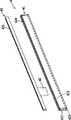
图3是该第一较佳实施例中,插接单元的分解图;Fig. 3 is an exploded view of the plug-in unit in the first preferred embodiment;
图4是该第一较佳实施例中,显示器外壳与显示面板的分解侧视图;Fig. 4 is an exploded side view of the display case and the display panel in the first preferred embodiment;
图5是该第一较佳实施例中,卡掣件设置在显示器外壳的局部剖视图;Fig. 5 is a partial cross-sectional view of the first preferred embodiment, where the engaging member is arranged on the display housing;
图6是该第一较佳实施例中,显示面板组装在显示器外壳的侧视图;Fig. 6 is a side view of the display panel assembled in the display housing in the first preferred embodiment;
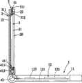
图7是该第一较佳实施例中,显示面板容置在显示器外壳的凹陷空间的侧视图;Fig. 7 is a side view of the display panel accommodated in the recessed space of the display housing in the first preferred embodiment;
图8是本实用新型第二较佳实施例中,插接单元的分解图;Fig. 8 is an exploded view of the plug-in unit in the second preferred embodiment of the present invention;
图9是该第二较佳实施例中,显示面板组装在显示器外壳的侧视图;以及Figure 9 is a side view of the display panel assembled in the display housing in the second preferred embodiment; and
图10是该第二较佳实施例中,显示面板容置在显示器外壳的凹陷空间的侧视图。Fig. 10 is a side view of the display panel accommodated in the recessed space of the display housing in the second preferred embodiment.
主要组件符号说明:Description of main component symbols:
1……………主机 4……………插接单元1……………Main unit 4…………… Plug-in unit
11…………外壳 41…………壳件11…
12…………电子组件模块 411…………第一部位12…………
121…………主机板 412…………第二部位121………Mainboard 412………Second part
122…………硬盘 413…………容置空间122…………
123…………中央处理单元 414…………顶部开口123…………
13…………操作界面 41’…………壳件13…………Operation interface 41’………Shell
131…………键盘组 411’…………第一部位131…………Keyboard set 411’…………The first part
132…………触控板 411a………第一本体132…………Touchpad 411a………The first body
2……………显示器外壳 411b………第一凸耳2……………Display housing 411b……First lug
20…………凹陷空间 412’………第二部位20…………Sunken space 412’………Second part
200…………显示器模块 412a………第一本体200…………Display module 412a………First body
21…………背板 412b………第二凸耳21………Back plate 412b……Second lug
22…………框体 413’………容置空间22………Frame 413’……Accommodating space
220…………框条 414’………顶部开口220………Frame bars 414’………Opening at the top
221…………定位凹槽 42…………挠性信号连接件221……
23…………容置槽 43…………第一电性插接件23………Accommodating
24…………第一定位槽 431…………插槽24………The
25…………第二定位槽 5……………卡掣件25………
3……………显示面板 51…………本体3……………
31…………面板单元 511…………操作部31…………
311…………卡槽 512…………端部311………Slot 512………End
32…………第二电性插接件 52…………弹性卡合部32…………Second
321…………电路板 521…………弹性臂321…………
322…………接触端子 522…………凸柱322…………Contact terminal 522………Protruding post
33…………定位凸片33………Positioning tabs
具体实施方式Detailed ways
有关本实用新型的前述及其他技术内容、特点与功效,在以下配合参考附图的二个较佳实施例的详细说明中,将可清楚地呈现。The aforementioned and other technical contents, features and effects of the present utility model will be clearly presented in the following detailed description of two preferred embodiments with reference to the accompanying drawings.
在本实用新型被详细描述之前,要注意的是,在以下的说明内容中,类似的组件是以相同的编号来表示。Before the present invention is described in detail, it should be noted that in the following description, similar components are denoted by the same numerals.
参阅图1、图2,本实用新型的显示面板易拆装的电子装置的第一较佳实施例是以一笔记本型计算机为例作说明,其包含一主机1及一显示器模块200。显示器模块200包括一连接在主机1的显示器外壳2、一显示面板3及一插接单元4。显示面板3可藉由插接单元4与主机1电性连接并且容置在显示器外壳2,或藉由与插接单元4分离而解除与主机1的电性连接并且移出显示器外壳2,藉此,显示面板3具有较高的拆装机动性。Referring to FIG. 1 and FIG. 2 , the first preferred embodiment of the electronic device with easily detachable display panel of the present invention is illustrated by taking a notebook computer as an example, which includes a
参阅图2、图4,主机1包括一外壳11、一设置在外壳11内的电子组件模块12以及一设置于外壳11并且外露于外壳11顶面的操作界面13,在本实施例中,电子组件模块12至少包括一主机板121、一与主机板121电性连接的硬盘122以及一设置在主机板121的中央处理单元123,当然,电子组件模块12可能还包括其他如显示卡、存储卡等足以让主机1运作的电子组件,在此便不一一说明。操作界面13包括一键盘组131以及一触控板132。2 and 4, the
在本实施例中,显示器外壳2包括一背板21以及一结合在背板21前面的框体22,背板21及框体22的底缘共同界定出显示器外壳2的底部而枢设在主机1的外壳11上,框体22结合在背板21前面而界定出一由前往后凹陷的凹陷空间20,且配合参阅图5,在本实施例中,框体22下方的框条220内侧还凹陷形成有连通凹陷空间20的定位凹槽221,其作用稍后说明。In this embodiment, the
参阅图2、图3、图4,插接单元4包括一壳件41、一挠性信号连接件42以及一第一电性插接件43。壳件41包括上下相连接的一第一部位411及一第二部位412,第一部位411形成有一供容置第一电性插接件43的容置空间413且顶部形成有一连通容置空间413的顶部开口414,在本实施例中,第一部位411与第二部位412为一体成型的结构并且大致呈中空扁平管状,其材质为可挠性材质,藉此,如图2及图4所示,第一部位411能相对于第二部位412前后位移而使壳件41局部弯曲变形。第一电性插接件43设置在第一部位411内,其实际结构可以是一插槽电连接器并且具有一狭长插槽431以及多个设置在插槽431内的接触端子(图未示)。在本实施例中,壳件41设置在显示器外壳2的背板21与框体22之间,第一电性插接件43的插槽431能藉由第一部位411的顶部开口414外露于显示器外壳2的凹陷空间20,且在本实施例中,为使第一部位411能相对于第二部位412往前位移,壳件41设置在显示器外壳2时,第一部位411外露于框体22的凹陷空间20。Referring to FIG. 2 , FIG. 3 , and FIG. 4 , the plug unit 4 includes a
挠性信号连接件42在本实施例中为一软性排线,其一端穿伸通过壳件41的第二部位412并且伸入第一部位411内与第一电性插接件43的这些接触端子电性连接,另一端则延伸入主机1的外壳11内并且与主机板121电性连接,藉由挠性信号连接件42的连接,使得位于壳件41内的第一电性插接件43具有连同壳件41的第一部位411活动的可活动性。The
显示面板3包括一用以显示影像的面板单元31、至少一形成在面板单元31底缘的定位凸片33、一设置在面板单元31底部的第二电性插接件32,在本实施例中,定位凸片33的数目为多个,且框体22定位凹槽221的数目是对应定位凸片33的数目,第二电性插接件32包括一电路板321以及多个设置在电路板321上的接触端子322,这些接触端子322为铜箔电路形成。The
参阅图2、图4,先行说明的是,由于壳件41的第一部位411能相对于第二部位412前后位移,故在显示面板3未组装于显示器外壳2之前,可先调整使壳件41的第一部位411相对于第二部位412略呈往前倾斜的状态,方便显示面板3的第二电性插接件32插入插接单元4的第一电性插接件43。Referring to Fig. 2 and Fig. 4, it is explained in advance that since the
参阅图4、图6、图7,欲将显示面板3组装在显示器外壳2时,藉由将面板单元31底缘的定位凸片33伸入显示器外壳2的定位凹槽221内,使显示面板3先与显示器外壳2达成初步的对准、定位之后,再将显示面板3的第二电性插接件32经第一部位411的顶部开口414插入位于第一部位411内的第一电性插接件43的插槽431,便可让面板单元31藉由挠性信号连接件42与主机1的主机板121电性连接,接着,再将面板单元31藉由第一部位411能相对于第二部位412位移的能力而相对于显示器外壳2往后位移,使面板单元31能被置入凹陷空间20内,即可完成显示面板3的组装。Referring to Fig. 4, Fig. 6 and Fig. 7, when the
参阅图1、图5~图7,为使面板单元31能较稳定的定位在显示器外壳2的凹陷空间20内,本实施例还包含一设置在显示器外壳2并且能相对于显示器外壳2上下位移的卡掣件5,而显示器外壳2位于凹陷空间20的上方还形成有一供设置卡掣件5的容置槽23以及分别位于容置槽23左右两侧的二第一定位槽24以及分别位于两第一定位槽24下方的二第二定位槽25,此外,较佳的,面板单元31顶缘还可凹陷形成有一卡槽311。1, 5 to 7, in order to enable the
参阅图5、图6、图7,卡掣件5包括一本体51以及二弹性卡合部52,本体51是设置在容置槽23内并且大致呈板状,且本体51具有一操作部511、一由操作部511往下延伸的端部512,两弹性卡合部52由操作部511往下延伸并且分别位于端部512两侧,每一弹性卡合部52具有一间隔于端部512的弹性臂521以及由弹性臂521末端横向延伸并且末端呈圆头状的凸柱522,两弹性卡合部52的凸柱522能分别位于两第一定位槽24或两第二定位槽25,且由于弹性臂521而使凸柱522具有横向位移的弹性。当卡掣件5相对于显示器外壳2上下位移时,藉由两弹性卡合部52的凸柱522分别伸入两第一定位槽24或两第二定位槽25,卡掣件5能定位在上下二个位置,且当卡掣件5是处在两弹性卡合部52的凸柱522分别伸入两第二定位槽25的位置时,其本体51的端部512伸入显示器外壳2的凹陷空间20内。Referring to Fig. 5, Fig. 6 and Fig. 7, the locking
因此,当面板单元31容置在显示器外壳2的凹陷空间20时,藉由将卡掣件5相对于显示器外壳2往下位移,使两弹性卡合部52的凸柱522分别位于两第二定位槽25,便能让卡掣件5本体51的端部512伸入面板单元31顶缘的卡槽311内而与面板单元31形成干涉,藉此将面板单元31限制在显示器外壳2的凹陷空间20内。Therefore, when the
而欲将显示面板3由显示器外壳2移出时,藉由将卡掣件5往上位移,使其两弹性卡合部52分别往上移至两第一定位槽24,此时,卡掣件5的端部512退出面板单元31的卡槽311以及显示器外壳2的凹陷空间20,因而解除卡掣件5与面板单元31的干涉,接着,便能将面板单元31相对于显示器外壳2往前枢转而移出凹陷空间20,再将面板单元31往上位移,使第二电性插接件32往上脱离第一电性插接件43,便能将显示面板3由显示器外壳2完全分离。When the
补充说明的是,显示器外壳2顶部供卡掣件5设置的容置槽23可以视实际结构设计的需求而形成在框体22或位于背板21与框体22之间。It is supplemented that the
除此之外,在其他的实施形式中,卡掣件5两侧的两个弹性卡合部52也可以只有其中一个,而对应的第一定位槽24及第二定位槽25也同样分别只有一个。In addition, in other implementation forms, only one of the two elastic engaging
如上所述,本实施例藉由将显示面板3与主机1之间以设有接触端子322的电路板321与插槽431相插接结合的方式电性连接,而达到以类似于适配卡与插槽之间插卡连接的方式,使显示面板3能被轻易的组装及拆离,因而具有较佳的拆装机动性,此外,亦可省去显示面板3与主机1之间理线以及拉线的问题。As mentioned above, in this embodiment, the
再一提的是,在本实施例中,显示器模块200是与主机1配合呈笔记本型计算机的形式,但本实用新型的显示面板与显示器外壳之间通过第一电性插接件与第二电性插接件相插接而结合以及利用卡掣件辅助定位的技术概念,也可以应用在一般桌上型的显示器而具有面板单元快拆装的功效,换句话说,显示器模块也可以是独立的机体。It should be mentioned again that in this embodiment, the
此外,本实施例的电子装置是以笔记本型计算机为例,但其也可以是手机、PDA、游戏机等各种掌上型电子装置或其他具有影像显示功能的电子装置。In addition, the electronic device in this embodiment is a notebook computer as an example, but it may also be various handheld electronic devices such as mobile phones, PDAs, game consoles, or other electronic devices with image display functions.
参阅图8、图9、图10,为本实用新型的第二较佳实施例,在第二较佳实施例中,不同的结构是在于插接单元4的壳件41’,壳件41’同样包括相连接的一第一部位411’及一第二部位412’,只是,在第二较佳实施例中,第一部位411’及第二部位412’为两独立的组件。第一部位411’包括一呈中空扁平管状的第一本体411a以及多个由第一本体411a往下延伸的第一凸耳411b,第一本体411a形成有一可供容置第一电性插接件43的容置空间413’以及一连通容置空间413’的顶部开口414’。第二部位412’包括一呈中空扁平管状的第二本体412a以及多个由第二本体412a往上延伸的第二凸耳412b,第一部位411’与第二部位412’藉由其第一凸耳411b与第二凸耳412b上下相枢接因而第一部位411’能相对于第二部位412’枢转活动。Referring to Fig. 8, Fig. 9 and Fig. 10, it is the second preferred embodiment of the present utility model. In the second preferred embodiment, the different structure lies in the shell part 41' of the plug-in unit 4, and the shell part 41' It also includes a connected first part 411' and a second part 412', but in the second preferred embodiment, the first part 411' and the second part 412' are two independent components. The first part 411' includes a hollow flat tubular first body 411a and a plurality of first lugs 411b extending downward from the first body 411a. The accommodating space 413' of the
将显示面板3藉由其第二电性插接件32插接在插接单元4的第一电性插接件43后,藉由壳件41’的第一部位411’能相对于第二部位412’枢转活动的能力,便能将面板单元31往后置入显示器外壳2的凹陷空间20,再将卡掣件5相对于显示器外壳2往下位移,使卡掣件5的端部512伸入面板单元31顶缘的卡槽311内而与面板单元31形成干涉,便能将面板单元31限制在显示器外壳2的凹陷空间20内。After the
综上所述,本实用新型藉由在显示器外壳及面板单元设置第一电性插接件及第二电性插接件,以供面板单元能藉由第一、第二电性插接件(例如是设有铜箔电路的电路板以及可供该电路板插设的插槽电连接器)的插接结合而组装在显示器外壳并且通过第一、第二电性插接件的插接结合与主机电性连接,或藉由分离第一、第二电性插接件而由显示器外壳分离,确实具有较高的拆装机动性,且藉由面板单元与主机通过第一、第二电性插接件插接结合的方式电性连接,亦可减少组装过程中拉线及理线的操作程序,故确实能达到本实用新型的目的。To sum up, the utility model arranges the first electrical connector and the second electrical connector on the display housing and the panel unit, so that the panel unit can be connected by the first and second electrical connectors. (For example, a circuit board with a copper foil circuit and a socket electrical connector that can be inserted into the circuit board) are assembled on the display housing and inserted through the first and second electrical connectors. Combined with the electrical connection with the host, or separated from the display case by separating the first and second electrical connectors, it does have high disassembly mobility, and through the panel unit and the host through the first and second The electric connectors are electrically connected in a plug-in combination mode, which can also reduce the operation procedures of pulling and arranging wires during the assembly process, so the purpose of the utility model can be achieved indeed.
惟以上所述的内容,仅为本实用新型的较佳实施例而已,应当不能以此限定本实用新型实施的范围,即凡是依本实用新型权利要求书范围及实用新型说明内容所作的简单的等同变化与修饰,皆仍属本实用新型专利涵盖的范围内。But the content described above is only a preferred embodiment of the utility model, and should not limit the scope of implementation of the utility model with this, that is, all simple things done according to the scope of claims of the utility model and the content of the utility model description Equivalent changes and modifications all still belong to the scope covered by the utility model patent.
Claims (38)
Translated fromChinesePriority Applications (1)
| Application Number | Priority Date | Filing Date | Title |
|---|---|---|---|
| CN2009201541697UCN201440227U (en) | 2009-05-13 | 2009-05-13 | Display module, related electronic device and combination of host and display shell |
Applications Claiming Priority (1)
| Application Number | Priority Date | Filing Date | Title |
|---|---|---|---|
| CN2009201541697UCN201440227U (en) | 2009-05-13 | 2009-05-13 | Display module, related electronic device and combination of host and display shell |
Publications (1)
| Publication Number | Publication Date |
|---|---|
| CN201440227Utrue CN201440227U (en) | 2010-04-21 |
Family
ID=42544890
Family Applications (1)
| Application Number | Title | Priority Date | Filing Date |
|---|---|---|---|
| CN2009201541697UExpired - LifetimeCN201440227U (en) | 2009-05-13 | 2009-05-13 | Display module, related electronic device and combination of host and display shell |
Country Status (1)
| Country | Link |
|---|---|
| CN (1) | CN201440227U (en) |
Cited By (4)
| Publication number | Priority date | Publication date | Assignee | Title |
|---|---|---|---|---|
| CN104007789A (en)* | 2013-02-27 | 2014-08-27 | 纬创资通股份有限公司 | Electronic equipment and socket type touch device |
| CN104679135A (en)* | 2013-11-15 | 2015-06-03 | 联想(新加坡)私人有限公司 | Electronic system |
| CN110785032A (en)* | 2019-12-03 | 2020-02-11 | 宁波奥克斯电气股份有限公司 | Drive-by-wire ware and air conditioner |
| CN111061345A (en)* | 2020-01-09 | 2020-04-24 | 合肥市卓怡恒通信息安全有限公司 | Detachable all-in-one machine |
- 2009
- 2009-05-13CNCN2009201541697Upatent/CN201440227U/ennot_activeExpired - Lifetime
Cited By (5)
| Publication number | Priority date | Publication date | Assignee | Title |
|---|---|---|---|---|
| CN104007789A (en)* | 2013-02-27 | 2014-08-27 | 纬创资通股份有限公司 | Electronic equipment and socket type touch device |
| CN104679135A (en)* | 2013-11-15 | 2015-06-03 | 联想(新加坡)私人有限公司 | Electronic system |
| CN104679135B (en)* | 2013-11-15 | 2018-04-24 | 联想(新加坡)私人有限公司 | Electronic system |
| CN110785032A (en)* | 2019-12-03 | 2020-02-11 | 宁波奥克斯电气股份有限公司 | Drive-by-wire ware and air conditioner |
| CN111061345A (en)* | 2020-01-09 | 2020-04-24 | 合肥市卓怡恒通信息安全有限公司 | Detachable all-in-one machine |
Similar Documents
| Publication | Publication Date | Title |
|---|---|---|
| CN102324656B (en) | Electrical connector and combination thereof | |
| CN100530036C (en) | Expansion device for removable adapter card | |
| US8109772B2 (en) | USB based expresscard device | |
| CN102420373B (en) | Electrical connectors and combinations thereof | |
| CN201107817Y (en) | Expansion card socket combination | |
| CN206340697U (en) | USB connecting device | |
| CN201440227U (en) | Display module, related electronic device and combination of host and display shell | |
| CN201754447U (en) | miniature electrical connector | |
| CN101662084B (en) | Electronic card connector and assembly method thereof | |
| CN201430318Y (en) | Electric connector | |
| CN204858056U (en) | socket electronic connector | |
| CN202454842U (en) | Electric connector with built-in signal gain circuit | |
| CN202633671U (en) | Flexible cable assembly | |
| CN220692264U (en) | A fixing bracket and battery pack for wiring harness plug-in port | |
| CN201590579U (en) | Laminated electric connector | |
| CN206340744U (en) | Type-C connector with display port connector appearance | |
| CN201332182Y (en) | Connector with control and storage function | |
| CN215771654U (en) | TYPE C and USB single face socket connector | |
| CN213750832U (en) | Electronic device | |
| CN202076642U (en) | Combined type connector | |
| CN207233975U (en) | Type C flexible PCBs | |
| TWM468043U (en) | Slim communication connector and electronic device using the same | |
| CN201402873Y (en) | Connector with projection function | |
| CN201303181Y (en) | Electric connector | |
| CN201149934Y (en) | Improved structure of connector filter module |
Legal Events
| Date | Code | Title | Description |
|---|---|---|---|
| C14 | Grant of patent or utility model | ||
| GR01 | Patent grant | ||
| CX01 | Expiry of patent term | Granted publication date:20100421 | |
| CX01 | Expiry of patent term |