CN201439659U - Rotary disc cipher type lock for steering wheel of vehicle - Google Patents
Rotary disc cipher type lock for steering wheel of vehicleDownload PDFInfo
- Publication number
- CN201439659U CN201439659UCN2009200604082UCN200920060408UCN201439659UCN 201439659 UCN201439659 UCN 201439659UCN 2009200604082 UCN2009200604082 UCN 2009200604082UCN 200920060408 UCN200920060408 UCN 200920060408UCN 201439659 UCN201439659 UCN 201439659U
- Authority
- CN
- China
- Prior art keywords
- lock body
- fixed
- steering wheel
- password
- lock
- Prior art date
- Legal status (The legal status is an assumption and is not a legal conclusion. Google has not performed a legal analysis and makes no representation as to the accuracy of the status listed.)
- Expired - Fee Related
Links
- 230000000149penetrating effectEffects0.000abstract1
- 230000009286beneficial effectEffects0.000description1
- 230000007812deficiencyEffects0.000description1
- 238000010586diagramMethods0.000description1
- 230000000694effectsEffects0.000description1
- 238000000034methodMethods0.000description1
- 238000012986modificationMethods0.000description1
- 230000004048modificationEffects0.000description1
Images


Landscapes
- Lock And Its Accessories (AREA)
Abstract
Description
Translated fromChinese技术领域:Technical field:
本实用新型涉及汽车方向盘锁技术领域,尤其涉及一种转盘密码式汽车方向盘锁。The utility model relates to the technical field of automobile steering wheel locks, in particular to a turntable password type automobile steering wheel lock.
背景技术:Background technique:
近年来,由于汽车盗窃案的逐渐增加,汽车方向盘锁作为一种有效的汽车防盗锁具,已经被越来越多的车主使用。现有的汽车方向盘锁主要包括锁体,锁体的一端设有用于控制锁体开关的锁芯,锁芯内开设有锁孔,锁体的另一端安装有用于掣肘的把手,车主通过与锁孔匹配的钥匙来开关锁体,当锁体锁紧在方向盘上时,锁体上的把手形成掣肘的作用,使方向盘难以转动来达到防盗目的,但是,这种汽车方向盘锁的缺点是,车主容易因忘记带钥匙或者钥匙丢失使锁体不能打开,影响汽车的使用,而且,钥匙容易被他人复制而造成安全隐患。In recent years, due to the gradual increase of car theft cases, car steering wheel locks have been used by more and more car owners as an effective car anti-theft lock. Existing automobile steering wheel lock mainly comprises lock body, and one end of lock body is provided with the lock core that is used to control lock body switch, is provided with lock hole in the lock core, and the other end of lock body is equipped with the handle that is used for restraint, and car owner passes and lock The key that matches the hole is used to switch the lock body. When the lock body is locked on the steering wheel, the handle on the lock body forms a constraint, making it difficult to turn the steering wheel to achieve the purpose of anti-theft. However, the disadvantage of this kind of car steering wheel lock is that the owner It is easy to forget to bring the key or the key is lost so that the lock body cannot be opened, which affects the use of the car, and the key is easily copied by others to cause a safety hazard.
实用新型内容:Utility model content:
本实用新型的目的就是针对现有技术存在的不足而提供一种安全可靠性好的转盘密码式汽车方向盘锁。The purpose of the utility model is to provide a car steering wheel lock with a turntable password and good safety and reliability aiming at the deficiencies in the prior art.
为了实现上述目的,本实用新型采用的技术方案是:In order to achieve the above object, the technical solution adopted by the utility model is:
它包括锁体、用于控制锁体开关的锁体开启机构、转盘密码机构,锁体的一端安装有把手,锁体的另一端扣接固定有侧边外壳,侧边外壳的右端扣接固定在锁体上,侧边外壳的左端扣接固定有侧盖,锁体开启机构安装在侧边外壳内,转盘密码机构包括刻度盘、转轴、密码盘,转轴穿设在侧盖上,刻度盘固定在转轴凸出于侧盖左侧的一端,密码盘安装在转轴凸出于侧盖右侧的一端,密码盘上开设有用于控制锁体开启机构的凹槽。It includes a lock body, a lock body opening mechanism for controlling the lock body switch, and a turntable password mechanism. One end of the lock body is equipped with a handle, and the other end of the lock body is buckled and fixed with a side shell, and the right end of the side shell is buckled and fixed. On the lock body, the left end of the side shell is buckled and fixed with a side cover. The lock body opening mechanism is installed in the side shell. It is fixed on the end of the rotating shaft protruding from the left side of the side cover, and the code disk is installed on the end of the rotating shaft protruding from the right side of the side cover. The code disk is provided with a groove for controlling the opening mechanism of the lock body.
所述锁体包括外壳、可转动的扣接块,扣接块套接在外壳内,外壳内安装固定有固定板,固定板的中心处固定有中心环,扣接块的一端与中心环转动连接,扣接块的另一端与把手固定连接,侧边外壳的右端扣接固定在外壳的左端。The lock body includes a shell and a rotatable fastening block, the fastening block is sleeved in the shell, a fixed plate is installed and fixed in the shell, a central ring is fixed at the center of the fixed plate, and one end of the fastening block rotates with the central ring Connection, the other end of the fastening block is fixedly connected with the handle, and the right end of the side shell is fastened and fixed to the left end of the shell.
所述扣接块上成型有用于扣接方向盘的弧形凸块。An arc-shaped projection for fastening the steering wheel is formed on the fastening block.
所述锁体开启机构包括推钮、与密码盘的凹槽匹配的推杆、固定架,推杆的顶端凸出于侧边外壳的外侧,推钮固定在推杆的顶端,推杆的底端成型有插销;固定架固定在锁体的固定板上,固定架与固定板上分别开设有与插销对应的插孔,插销活动插接在固定架与固定板的插孔内,扣接块的左端开设有卡接孔,插销的右端置于卡接孔内。The lock body opening mechanism includes a push button, a push rod matched with the groove of the code disc, and a fixing frame. The top of the push rod protrudes from the outside of the side shell, the push button is fixed on the top of the push rod, and the bottom of the push rod The end is formed with a bolt; the fixed frame is fixed on the fixed plate of the lock body, and the fixed frame and the fixed plate are respectively provided with sockets corresponding to the bolts. The left end of the pin is provided with a clamping hole, and the right end of the latch is placed in the clamping hole.
所述插销上套设有弹簧、用于卡住弹簧的卡环。A spring and a snap ring for clamping the spring are sheathed on the bolt.
所述转盘密码机构的密码盘为三个。There are three code disks of the rotary disk code mechanism.
本实用新型有益效果在于:The beneficial effects of the utility model are:
本实用新型提供的转盘密码式汽车方向盘锁包括锁体、用于控制锁体开关的锁体开启机构、转盘密码机构,锁体的一端安装有把手,锁体的另一端扣接固定有侧边外壳,侧边外壳的右端扣接固定在锁体上,侧边外壳的左端扣接固定有侧盖,锁体开启机构安装在侧边外壳内,转盘密码机构包括刻度盘、转轴、密码盘,转轴穿设在侧盖上,刻度盘固定在转轴凸出于侧盖左侧的一端,密码盘安装在转轴凸出于侧盖右侧的一端,密码盘上开设有用于控制锁体开启机构的凹槽;本实用新型在使用时,只有通过转盘密码机构输入正确的密码,才能控制锁体开启机构打开锁体,当密码输入不正确时,无法打开锁体,因此,本实用新型与现有采用锁芯的汽车方向盘锁相比,具有较好的安全可靠性,而且无需携带钥匙,使用方便。The turntable cipher type automobile steering wheel lock provided by the utility model includes a lock body, a lock body opening mechanism for controlling the switch of the lock body, and a turntable cipher mechanism. One end of the lock body is equipped with a handle, and the other end of the lock body is buckled and fixed with a side Shell, the right end of the side shell is buckled and fixed on the lock body, the left end of the side shell is buckled and fixed with a side cover, the lock body opening mechanism is installed in the side shell, and the turntable password mechanism includes a dial, a rotating shaft, and a code disk. The rotating shaft is installed on the side cover, the dial is fixed on the end of the rotating shaft protruding from the left side of the side cover, and the code disc is installed on the end of the rotating shaft protruding from the right side of the side cover. Groove; when the utility model is in use, the lock body opening mechanism can be controlled to open the lock body only by inputting the correct password through the turntable password mechanism. When the password input is incorrect, the lock body cannot be opened. Therefore, the utility model is different from the existing Compared with the automobile steering wheel lock using the lock cylinder, it has better safety and reliability, and it is not necessary to carry a key, so it is easy to use.
附图说明:Description of drawings:
图1是本实用新型的结构示意图;Fig. 1 is a structural representation of the utility model;
图2是本实用新型隐去外壳和侧边外壳的结构示意图;Fig. 2 is a schematic structural view of the utility model without the shell and the side shell;
图3是图2中A处的放大示意图;Fig. 3 is the enlarged schematic diagram of place A in Fig. 2;
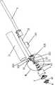
图4是本实用新型的分解示意图;Fig. 4 is the exploded schematic view of the utility model;
图5是图4中B处的放大示意图。FIG. 5 is an enlarged schematic view of B in FIG. 4 .
具体实施方式:Detailed ways:
下面结合附图对本实用新型作进一步的说明,请参考图1~5,本实用新型包括锁体1、用于控制锁体1开关的锁体开启机构2、转盘密码机构6,锁体1的一端安装有把手3,锁体1的另一端扣接固定有侧边外壳4,侧边外壳4的右端扣接固定在锁体1上,侧边外壳4的左端扣接固定有侧盖5,锁体开启机构2安装在侧边外壳4内,转盘密码机构6包括刻度盘61、转轴62、密码盘63,转轴62穿设在侧盖5上,更具体地说,转轴62可转动地穿设在侧盖5上,刻度盘61固定在转轴62凸出于侧盖5左侧的一端,密码盘63安装在转轴62凸出于侧盖5右侧的一端,密码盘63上开设有用于控制锁体开启机构2的凹槽631,当然,所述刻度盘61上标识有相应的刻度,使得使用者可以通过刻度盘61旋转拨动密码盘63来输入正确的密码。Below in conjunction with the accompanying drawings the utility model is further described, please refer to Figures 1 to 5, the utility model includes a
本实施例的锁体1包括外壳11、可转动的扣接块12,扣接块12套接在外壳11内,外壳11内安装固定有固定板13,固定板13的中心处固定有中心环131,扣接块12的一端与中心环131转动连接,扣接块12的另一端与把手3固定连接,侧边外壳4的右端扣接固定在外壳11的左端,所述扣接块12上成型有用于扣接方向盘的弧形凸块121,当需要锁住方向盘时,可通过握住并转动把手3,进而带动扣接块12旋转,使得扣接块12上的弧形凸块121扣住方向盘,同时,把手3形成掣肘的作用,使方向盘难以转动,从而达到防盗的目的。The
本实施例的锁体开启机构2包括推钮21、与密码盘63的凹槽631匹配的推杆22、固定架23,推杆22的顶端凸出于侧边外壳4的外侧,推钮21固定在推杆22的顶端,推杆22的底端成型有插销221;固定架23固定在锁体1的固定板13上,固定架23与固定板13上分别开设有与插销221对应的插孔,插销221活动插接在固定架23与固定板13的插孔内,扣接块12的左端开设有卡接孔122,插销221的右端置于卡接孔122内,使得插销221可以卡住扣接块12,阻止扣接块12的转动,所述插销221上套设有弹簧222、用于卡住弹簧222的卡环223;由上述结构可知,推杆22在推钮21的带动下,可前后活动,当推杆22被推入密码盘63的凹槽631中时,插销221在推杆22带动下向左滑动,使得插销221可以从扣接块12的卡接孔122内退出,令到扣接块12可以自由转动,实现开锁的目的。The lock
本实施例的转盘密码机构6的密码盘63为三个,三个密码盘63上均开设有用于控制锁体开启机构2的凹槽631,只有三个密码盘63上的凹槽631位于同一位置时,锁体开启机构2的推杆22才能插入凹槽631中,达到控制开锁的目的,当然,为了增加安全性,所述转盘密码机构6的密码盘63也可以为四个或者更多。There are three
由于本实用新型的转盘密码机构6预先设定有密码,在使用者通过刻度盘61旋转拨动密码盘63来输入密码的过程中,当输入的密码正确时,三个密码盘63上的凹槽631位于同一位置,刚好对应于锁体开启机构2的推杆22,此时,只要推动推钮21,使推杆22插入凹槽631中,并握住转动把手3,带动扣接块12旋转,就可以打开锁体1,从方向盘上取下锁体1;当输入的密码不正确时,三个密码盘63上的凹槽631不位于同一位置,此时,由于推杆22不能够插入密码盘63的凹槽631中,所以推钮21无法推动,把手3也不能转动,即不能打开锁体1;另外,当锁体1为打开状态时,可以握住转动把手3,带动扣接块12旋转,使扣接块12上的弧形凸块121扣住方向盘,即可锁住方向盘;所以,本实用新型与现有采用锁芯的汽车方向盘锁相比,具有较好的安全可靠性、无需携带钥匙,使用方便。Because the rotary
当然,以上所述仅是本实用新型的较佳实施例,故凡依本实用新型专利申请范围所述的构造、特征及原理所做的等效变化或修饰,均包括于本实用新型专利申请范围内。Of course, the above are only preferred embodiments of the utility model, so all equivalent changes or modifications made according to the structure, features and principles described in the scope of the utility model patent application are included in the utility model patent application within range.
Claims (6)
Translated fromChinesePriority Applications (1)
| Application Number | Priority Date | Filing Date | Title |
|---|---|---|---|
| CN2009200604082UCN201439659U (en) | 2009-07-14 | 2009-07-14 | Rotary disc cipher type lock for steering wheel of vehicle |
Applications Claiming Priority (1)
| Application Number | Priority Date | Filing Date | Title |
|---|---|---|---|
| CN2009200604082UCN201439659U (en) | 2009-07-14 | 2009-07-14 | Rotary disc cipher type lock for steering wheel of vehicle |
Publications (1)
| Publication Number | Publication Date |
|---|---|
| CN201439659Utrue CN201439659U (en) | 2010-04-21 |
Family
ID=42544329
Family Applications (1)
| Application Number | Title | Priority Date | Filing Date |
|---|---|---|---|
| CN2009200604082UExpired - Fee RelatedCN201439659U (en) | 2009-07-14 | 2009-07-14 | Rotary disc cipher type lock for steering wheel of vehicle |
Country Status (1)
| Country | Link |
|---|---|
| CN (1) | CN201439659U (en) |
Cited By (3)
| Publication number | Priority date | Publication date | Assignee | Title |
|---|---|---|---|---|
| CN102371971A (en)* | 2011-09-07 | 2012-03-14 | 深圳市道格科技有限公司 | Steering wheel lock of automotive vehicle |
| CN102371968A (en)* | 2011-07-18 | 2012-03-14 | 雷先鸣 | car steering wheel lock |
| CN106310558A (en)* | 2016-09-20 | 2017-01-11 | 陈志新 | Spherical safety device |
- 2009
- 2009-07-14CNCN2009200604082Upatent/CN201439659U/ennot_activeExpired - Fee Related
Cited By (5)
| Publication number | Priority date | Publication date | Assignee | Title |
|---|---|---|---|---|
| CN102371968A (en)* | 2011-07-18 | 2012-03-14 | 雷先鸣 | car steering wheel lock |
| CN102371971A (en)* | 2011-09-07 | 2012-03-14 | 深圳市道格科技有限公司 | Steering wheel lock of automotive vehicle |
| CN102371971B (en)* | 2011-09-07 | 2013-11-06 | 深圳市道格科技有限公司 | Steering wheel lock of automotive vehicle |
| CN106310558A (en)* | 2016-09-20 | 2017-01-11 | 陈志新 | Spherical safety device |
| CN106310558B (en)* | 2016-09-20 | 2022-04-01 | 陈志新 | Spherical safety device |
Similar Documents
| Publication | Publication Date | Title |
|---|---|---|
| JP2005112048A5 (en) | ||
| US11879274B2 (en) | Lock assembly for a bicycle | |
| JP2010509123A (en) | Luggage storage device for motorcycles | |
| CN201439659U (en) | Rotary disc cipher type lock for steering wheel of vehicle | |
| CN106760987B (en) | Puzzle lock | |
| CN204920524U (en) | Intelligent zipper lock for bags | |
| EP2313586A1 (en) | Anti-theft devices for portable objects such as laptops | |
| EP4320325B1 (en) | Half-cylinder lock | |
| CN211448183U (en) | Padlock capable of preventing accidental unlocking | |
| CN206581716U (en) | Padlock with lock cylinder unlocking indication function | |
| CN205637860U (en) | Prevent door handle mechanism that cat eye opened | |
| CN111863501A (en) | Keyless start ignition lock with optional unlock function | |
| CN109637870A (en) | A kind of integral-type keyless ignition switch | |
| JP5067902B2 (en) | Charging cable lock device | |
| CN111706163B (en) | A password unlocking handle | |
| CN110836052A (en) | Padlock capable of preventing accidental unlocking | |
| CN207245403U (en) | A kind of well-set luggage combination lock | |
| CN204055713U (en) | Combination lock for automobile steering wheel | |
| CN2900714Y (en) | Movement module for electronic locks | |
| CN204368328U (en) | A kind of igniting switch for motorcycle | |
| CN201318063Y (en) | Encrypted night lock core | |
| TWI593867B (en) | Padlock with wireless opening and closing function | |
| CN216110195U (en) | Novel luggage coded lock | |
| CN202544527U (en) | Lock cylinder | |
| TWM553702U (en) | Structure of unlocking bicycle by sensing |
Legal Events
| Date | Code | Title | Description |
|---|---|---|---|
| C14 | Grant of patent or utility model | ||
| GR01 | Patent grant | ||
| C17 | Cessation of patent right | ||
| CF01 | Termination of patent right due to non-payment of annual fee | Granted publication date:20100421 Termination date:20120714 |