CN201402455Y - Infrared touch screen frame structure - Google Patents
Infrared touch screen frame structureDownload PDFInfo
- Publication number
- CN201402455Y CN201402455YCN2009200524660UCN200920052466UCN201402455YCN 201402455 YCN201402455 YCN 201402455YCN 2009200524660 UCN2009200524660 UCN 2009200524660UCN 200920052466 UCN200920052466 UCN 200920052466UCN 201402455 YCN201402455 YCN 201402455Y
- Authority
- CN
- China
- Prior art keywords
- touch screen
- infrared
- frame
- touch panel
- infrared touch
- Prior art date
- Legal status (The legal status is an assumption and is not a legal conclusion. Google has not performed a legal analysis and makes no representation as to the accuracy of the status listed.)
- Expired - Fee Related
Links
- 239000000463materialSubstances0.000claimsdescription5
- 230000003287optical effectEffects0.000claimsdescription4
- 239000012780transparent materialSubstances0.000claimsdescription4
- 229920003023plasticPolymers0.000claimsdescription3
- 239000004568cementSubstances0.000claims1
- 238000004519manufacturing processMethods0.000abstractdescription8
- 238000009434installationMethods0.000abstractdescription6
- 238000001125extrusionMethods0.000abstractdescription4
- 238000001514detection methodMethods0.000description4
- 238000010586diagramMethods0.000description4
- 230000008093supporting effectEffects0.000description3
- 238000006073displacement reactionMethods0.000description2
- 238000012423maintenanceMethods0.000description2
- 238000000034methodMethods0.000description2
- VVQNEPGJFQJSBK-UHFFFAOYSA-NMethyl methacrylateChemical compoundCOC(=O)C(C)=CVVQNEPGJFQJSBK-UHFFFAOYSA-N0.000description1
- 229920005372Plexiglas®Polymers0.000description1
- 230000009286beneficial effectEffects0.000description1
- 238000005034decorationMethods0.000description1
- 230000007547defectEffects0.000description1
- 230000000694effectsEffects0.000description1
- 238000005516engineering processMethods0.000description1
- 239000011521glassSubstances0.000description1
- 239000002184metalSubstances0.000description1
Images


Landscapes
- Position Input By Displaying (AREA)
Abstract
Translated fromChinese
Description
Translated fromChinese技术领域technical field
本实用新型涉及一种利用红外线发射、接收元器件组成的触摸屏技术。The utility model relates to a touch screen technology composed of infrared emitting and receiving components.
背景技术Background technique
现有的红外线触摸屏涉及中惯常使用的用于固定红外线发射、接收电路板的触摸屏框架的结构,由于设计笨重,结构不够紧凑,设计不合理,不美观,安装复杂及制造成本高等因素,以及在设计上有很多地方没有考虑到使用者的需要,缺乏人性化的设计,在实际使用当中导致产品不能够很好的与现有的电脑显示器、大型LCD或PDP电视或显示终端上配合使用,甚至导致某些终端显示器上无法实现安装等情况。而另一方面,在现有技术中往往需要针对性的根据显示器的大小结构进行模具开发,使产品的成本上升,无法广泛使用。The existing infrared touch screen involves the structure of the touch screen frame commonly used for fixing the infrared ray emitting and receiving circuit boards. Due to the heavy design, compact structure, unreasonable design, unsightly appearance, complicated installation and high manufacturing cost, as well as factors such as There are many places in the design that do not consider the needs of users and lack humanized design. In actual use, the product cannot be used well with existing computer monitors, large LCD or PDP TVs or display terminals, and even As a result, the installation cannot be realized on some terminal displays. On the other hand, in the prior art, it is often necessary to develop molds according to the size and structure of the display, which increases the cost of the product and cannot be widely used.
发明内容Contents of the invention
本实用新型的目的是克服现有技术中的缺陷,提供一种结构简单、容易量化生产,无需针对不同尺寸显示器所需要的框架结构开模制造,进行再次开发的新型红外线触摸屏结构。The purpose of the utility model is to overcome the defects in the prior art and provide a new infrared touch screen structure which is simple in structure, easy to quantify and produce, and does not need to open molds for frame structures required by displays of different sizes.
本实用新型的技术解决方案是:一种红外线触摸屏框架结构,包括具有开口且粘贴设置在触摸屏上的框架,以及设置在框架内的红外线发射、接收电路板,在所述框架的侧壁上设有可滑动的固定件。The technical solution of the utility model is: an infrared touch screen frame structure, including a frame with an opening and pasted on the touch screen, and an infrared emitting and receiving circuit board arranged in the frame, and the side wall of the frame is provided with There are slidable fixings.
框架可以直接粘贴在触摸屏上,其侧壁上设有的固定件可以用于进一步将框架固定在现有的触摸屏上,由于固定件可沿着框架的侧壁滑动,可以根据不同尺寸显示器需要,灵活选择设置固定的位置,结构简单,容易量化生产;同时由于框架直接通过粘贴方式固定,固定件起到加强固定的效果,设置比较容易,可以同时适用不同尺寸的触摸屏上。The frame can be directly pasted on the touch screen, and the fixing piece on the side wall can be used to further fix the frame on the existing touch screen. Since the fixing piece can slide along the side wall of the frame, it can be customized according to the needs of displays of different sizes. Flexible choice of fixed position, simple structure, easy to quantify production; at the same time, because the frame is directly fixed by pasting, the fixing parts can strengthen the fixing effect, the setting is relatively easy, and it can be applied to touch screens of different sizes at the same time.
在所述框架侧壁上设有带滑块的凹槽,所述固定件连接在滑块上,这样可以预制滑块和凹槽,固定件可随滑块在框架的任一位置固定,进一步提高了安装在各种尺寸显示器的适用性。A groove with a slider is provided on the side wall of the frame, and the fixing piece is connected to the slider, so that the slider and the groove can be prefabricated, and the fixing piece can be fixed at any position of the frame along with the slider, further Improved suitability for mounting on monitors of various sizes.
所述框架的侧壁与所述触摸屏上表面平齐。这样的触摸屏结构可以利用现有显示屏,直接在周边设置框架即可形成红外线触摸屏,方便使用。The side wall of the frame is flush with the upper surface of the touch screen. Such a touch screen structure can utilize an existing display screen, and directly arrange a frame around the periphery to form an infrared touch screen, which is convenient to use.
所述框架的侧壁向所述触摸屏的底部延伸,框架的侧壁可以包覆在触摸屏的侧壁外,组装后起到从侧面支撑触摸屏的作用,提高红外线触摸屏结构的整体稳定性。The side wall of the frame extends to the bottom of the touch screen, and the side wall of the frame can cover the side wall of the touch screen, and play a role in supporting the touch screen from the side after assembly, improving the overall stability of the infrared touch screen structure.
所述框架的开口处设有红外光学材料或透明材料的挡板。可以保护腔室内的电路元器件,同时还可以过滤外界的光线干扰。The opening of the frame is provided with a baffle of infrared optical material or transparent material. It can protect the circuit components in the chamber, and can also filter the interference of external light.
所述的固定件为吊耳或挂钩,当外用时可选择挂钩,结构简单,便于加工,适应性强,内置时可以选用吊耳,安装容易。The fixing part is a hanging lug or a hook, and the hook can be selected for external use. The structure is simple, easy to process, and has strong adaptability. The hanging lug can be selected for built-in, and the installation is easy.
所述红外线发射、接收管安装于朝向所述触摸屏侧的红外线发射、接收电路板上。这样发射的红外线与触摸屏表面之间的空隙较小,可以显著减少其实际接触点与检测点之间的位移偏差,进一步提高触摸检测的准确度。The infrared emitting and receiving tubes are installed on the infrared emitting and receiving circuit board facing the side of the touch screen. In this way, the gap between the emitted infrared rays and the surface of the touch screen is small, which can significantly reduce the displacement deviation between the actual contact point and the detection point, and further improve the accuracy of touch detection.
所述触摸屏相邻两条边的边缘设置的两个框架之间通过L型连接器连接。L型连接器的两个端壁分别伸入两侧的框架内,并分别固定在框架内,这样连接的的优点是隐蔽性好,整体设计美观,连接结构牢固,便于拆卸及维护。The two frames arranged at the edges of two adjacent sides of the touch screen are connected through an L-shaped connector. The two end walls of the L-shaped connector extend into the frames on both sides and are respectively fixed in the frames. The advantages of this connection are good concealment, beautiful overall design, firm connection structure, and easy disassembly and maintenance.
所述框架内设有可容纳所述L型连接器的端壁的开槽。L型连接器的端壁可以直接插入开槽内,免去使用工具进行的连接,方便操作。The frame is provided with a slot capable of accommodating the end wall of the L-shaped connector. The end wall of the L-shaped connector can be directly inserted into the slot, eliminating the need to use tools for connection, which is convenient for operation.
所述触摸屏相邻两条边的边缘设置的两个框架外侧设有固定塑胶转角。通过螺丝将两侧的框架连接和固定成一体,进一步提高整体结构的稳定性,同时可以起到装饰、保护的作用。Fixed plastic corners are provided on the outer sides of the two frames arranged at the edges of two adjacent sides of the touch screen. The frames on both sides are connected and fixed into one body by screws, which further improves the stability of the overall structure, and can play the role of decoration and protection at the same time.
本实用新型的优点是:由于采用的是框架设置在触摸屏上的结构方式,固定件设置在触摸屏的侧面,对触摸屏的厚度没有要求,大大增加了产品安装时的灵活性,且各种配件都可以利用挤压模具制造成一个标准的配件,然后可随时根据不同需要切割出不同尺寸的部件,用于制造不同尺寸的红外线触摸屏。本实用新型还具有容易安装、拆卸,维护方便等特点,结构紧凑美观,相应的生产成本还较低。同时没有在红外线发射、接收电路板与触摸屏表面之间设置有任何配件,使得红外线发射、接收电路板安装后显著减少了红外管距离触摸屏的高度,特别是还可以使红外管紧贴触摸屏表面,解决了现有红外线触摸屏装置检测触摸位置偏移的问题,保证定位准确。The utility model has the advantages that: because the frame is arranged on the touch screen, and the fixing parts are arranged on the side of the touch screen, there is no requirement for the thickness of the touch screen, which greatly increases the flexibility of product installation, and various accessories are all available. It can be made into a standard accessory by using an extrusion die, and then parts of different sizes can be cut out according to different needs at any time to manufacture infrared touch screens of different sizes. The utility model also has the characteristics of easy installation and disassembly, convenient maintenance, compact and beautiful structure, and relatively low production cost. At the same time, there are no accessories between the infrared emitting and receiving circuit board and the surface of the touch screen, so that the height of the infrared tube from the touch screen is significantly reduced after the infrared emitting and receiving circuit board is installed, especially the infrared tube can be closely attached to the surface of the touch screen. The problem that the existing infrared touch screen device detects the deviation of the touch position is solved, and the positioning accuracy is ensured.
附图说明Description of drawings
附图1为本实用新型实施例1结构示意图;Accompanying
附图2为本实用新型实施例1中框架的结构简图;Accompanying
附图3为本实用新型实施例1的组装结构示意图;
附图4为本实用新型实施例2中框架的结构简图;Accompanying
附图5为本实用新型实施例2中的组装结构示意图;
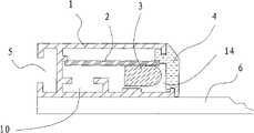
1、框架,2、红外线发射、接收电路板,3、红外线发射、接收管,4、挡板,5、凹槽,6、触摸屏,7、固定件,8、固定螺丝,9、L型连接器,10、开槽,11、滑块,12、螺丝,13、塑胶转角,14、开口。1. Frame, 2. Infrared emitting and receiving circuit board, 3. Infrared emitting and receiving tube, 4. Baffle, 5. Groove, 6. Touch screen, 7. Fixing piece, 8. Fixing screw, 9. L-shaped connection Device, 10, slotting, 11, slide block, 12, screw, 13, plastic corner, 14, opening.
具体实施方式Detailed ways
实施例1:Example 1:
参阅图1、2和3,一种红外线触摸屏框架结构,包括沿触摸屏6四周边沿分别设置的四条具有开口14且粘贴设置在触摸屏6上的框架1,以及设置在框架1内的红外线发射、接收电路板2,在所述框架1的侧壁上设有可滑动的固定件7,在所述框架1的侧壁上设有带滑块11的凹槽5,滑块11上通过固定螺丝8连接有固定件7。所述红外线发射、接收管安装于朝向所述触摸屏侧的红外线发射、接收电路板上。这样发射的红外线与触摸屏表面之间的空隙较小,可以显著减少其实际接触点与检测点之间的位移偏差,进一步提高触摸检测的准确度。其中框架1为金属型材通过挤压模制而成,其侧壁向触摸屏6的底部延伸,这样,框架1的侧壁延伸部可以包覆在触摸屏6的侧壁外,组装后起到从侧面支撑触摸屏的作用,提高红外线触摸屏结构的整体稳定性。Referring to Figures 1, 2 and 3, an infrared touch screen frame structure includes four
所述框架1的开口14处设有红外光学材料或透明材料的挡板4,该档板4所使用的材料可由红外光学材料或透明材料或有机玻璃利用挤压模制成的标准配件。该设置的档板4可以保护空腔内的电路元器件,同时还可以过滤外界的光线干扰。The
所述触摸屏6相邻两条边的边缘设置的两个框架1之间通过L型连接器9连接,框架1内设有可容纳所述L型连接器9的端壁的开槽10。该L形连接器9的两个端壁分别插入相邻的两个框架1内的开槽10内,连接和固定两个框架1。The two
在框架1的侧壁上设置有一个凹槽5,在凹槽5内可放置一个滑块11,可在凹槽5内自由移动,安装在触摸屏6上时,可先将框架1黏贴在触摸屏6的表面上,再将固定件7与滑块11利用固定螺丝8连接,在将固定件7移动至所需要的位置上时,将固定螺丝8锁死。本实施例中固定件7是挂钩,也可以是吊耳,方便设置在显示器内固定使用。A
实施例1的优点是,框架侧壁对触摸屏6具有支撑作用,适合使用在较厚较大型的触摸屏结构中,而且由于各个螺孔的位置隐蔽性好,不影响整体设计外观,连接结构牢固机密,便于拆卸及维护。The advantage of
以上所有配件包括框架1,档板4、L形连接器9,滑块11,固定件7都是可以通过标准化生产的标准件,而利用这些标准件提供了能够批量生产的基本条件,在生产不同尺寸的触摸屏时,可根据需要,将每个标准件按所需尺寸切割,并按上述的装配结构安装成品。从而大大提高了触摸屏的生产量,及产品的种类,以及提高了产品更新换代的速度。All the above accessories including the
实施例2:Example 2:
参阅图4和5,一种红外线触摸屏框架结构,包括沿触摸屏6四周边沿分别设置的四条具有开口14且粘贴设置在触摸屏6上的框架1,以及设置在框架1内的红外线发射、接收电路板2,在所述框架1的侧壁上设有可滑动的固定件7,在所述框架1的侧壁上设有带滑块11的凹槽5,滑块11上通过固定螺丝8连接有固定件7。所述框架1的侧壁与所述触摸屏6上表面平齐。这样的框架可以直接适用于表面具有玻璃层的显示屏上,省去额外附加的触摸屏,有利于节省成本,不破换原有显示屏的整体设计,提高整体美观度。其他技术特征与实施例1相同,在此不予赘述。Referring to Figures 4 and 5, an infrared touch screen frame structure includes four
上列详细说明是针对本实用新型可行实施例的具体说明,该实施例并非用以限制本实用新型的专利范围,凡未脱离本实用新型所为的等效实施或变更,均应包含于本案的专利范围中。The above detailed description is a specific description of the feasible embodiment of the utility model. This embodiment is not used to limit the patent scope of the utility model. Any equivalent implementation or change that does not deviate from the utility model shall be included in this case within the scope of the patent.
Claims (10)
Priority Applications (1)
| Application Number | Priority Date | Filing Date | Title |
|---|---|---|---|
| CN2009200524660UCN201402455Y (en) | 2009-03-12 | 2009-03-12 | Infrared touch screen frame structure |
Applications Claiming Priority (1)
| Application Number | Priority Date | Filing Date | Title |
|---|---|---|---|
| CN2009200524660UCN201402455Y (en) | 2009-03-12 | 2009-03-12 | Infrared touch screen frame structure |
Publications (1)
| Publication Number | Publication Date |
|---|---|
| CN201402455Ytrue CN201402455Y (en) | 2010-02-10 |
Family
ID=41662252
Family Applications (1)
| Application Number | Title | Priority Date | Filing Date |
|---|---|---|---|
| CN2009200524660UExpired - Fee RelatedCN201402455Y (en) | 2009-03-12 | 2009-03-12 | Infrared touch screen frame structure |
Country Status (1)
| Country | Link |
|---|---|
| CN (1) | CN201402455Y (en) |
Cited By (7)
| Publication number | Priority date | Publication date | Assignee | Title |
|---|---|---|---|---|
| CN102208154A (en)* | 2011-06-02 | 2011-10-05 | 广州物联家信息科技股份有限公司 | Display with detachable frame |
| CN102629171A (en)* | 2012-03-30 | 2012-08-08 | 广东威创视讯科技股份有限公司 | Touch display device |
| CN102855022A (en)* | 2011-06-29 | 2013-01-02 | 奇美电子股份有限公司 | Touch screen structure and manufacturing method thereof |
| CN102955616A (en)* | 2012-11-27 | 2013-03-06 | 广东威创视讯科技股份有限公司 | Touch screen framework |
| CN103324364A (en)* | 2013-07-16 | 2013-09-25 | 山东共达电声股份有限公司 | Optical touch control device and touch screen |
| CN108984044A (en)* | 2018-07-28 | 2018-12-11 | 贵州华宁科技股份有限公司 | A kind of infrared touch panel |
| CN111061391A (en)* | 2018-10-17 | 2020-04-24 | 华为技术有限公司 | Infrared touch frame, infrared touch screen and display device |
- 2009
- 2009-03-12CNCN2009200524660Upatent/CN201402455Y/ennot_activeExpired - Fee Related
Cited By (11)
| Publication number | Priority date | Publication date | Assignee | Title |
|---|---|---|---|---|
| CN102208154A (en)* | 2011-06-02 | 2011-10-05 | 广州物联家信息科技股份有限公司 | Display with detachable frame |
| CN102208154B (en)* | 2011-06-02 | 2012-12-26 | 广州物联家信息科技股份有限公司 | Display with detachable frame |
| CN102855022A (en)* | 2011-06-29 | 2013-01-02 | 奇美电子股份有限公司 | Touch screen structure and manufacturing method thereof |
| CN102855022B (en)* | 2011-06-29 | 2015-09-16 | 群创光电股份有限公司 | Touch screen structure and manufacturing method thereof |
| CN102629171A (en)* | 2012-03-30 | 2012-08-08 | 广东威创视讯科技股份有限公司 | Touch display device |
| CN102955616A (en)* | 2012-11-27 | 2013-03-06 | 广东威创视讯科技股份有限公司 | Touch screen framework |
| CN102955616B (en)* | 2012-11-27 | 2016-03-02 | 广东威创视讯科技股份有限公司 | A kind of touch-screen framework |
| CN103324364A (en)* | 2013-07-16 | 2013-09-25 | 山东共达电声股份有限公司 | Optical touch control device and touch screen |
| CN103324364B (en)* | 2013-07-16 | 2016-08-17 | 山东共达电声股份有限公司 | Optical touch control apparatus and touch screen |
| CN108984044A (en)* | 2018-07-28 | 2018-12-11 | 贵州华宁科技股份有限公司 | A kind of infrared touch panel |
| CN111061391A (en)* | 2018-10-17 | 2020-04-24 | 华为技术有限公司 | Infrared touch frame, infrared touch screen and display device |
Similar Documents
| Publication | Publication Date | Title |
|---|---|---|
| CN201402455Y (en) | Infrared touch screen frame structure | |
| CN106341963A (en) | Housing for portable electronic device with reduced border region | |
| CN205983307U (en) | Mobile terminal | |
| CN103631039B (en) | A kind of integral type liquid crystal display and manufacture method thereof | |
| CN102055926A (en) | Split liquid crystal television and realizing method thereof | |
| CN201066498Y (en) | Novel infrared touch screen structure | |
| CN202346524U (en) | Elevator hall-call box and mounting structure of elevator hall-call box | |
| KR100969133B1 (en) | Flat Panel Display | |
| TWI630441B (en) | Display device | |
| CN206601689U (en) | A kind of touch-screen | |
| CN112114692A (en) | Infrared touch frame and display device | |
| CN205691900U (en) | Display | |
| CN205227540U (en) | Air conditioner | |
| CN201004684Y (en) | A combined color tube TV casing | |
| CN212211188U (en) | TV Backplane and LCD TV | |
| CN209356811U (en) | Liquid crystal display back light module unit structure | |
| CN202528359U (en) | Indoor unit panel mould for replaceable mold core insert | |
| CN202047521U (en) | Wallboard installing structure with 90-degree external corner | |
| CN205264269U (en) | Display screen metal frame | |
| CN201507102U (en) | Aluminium alloy section bar subassembly | |
| CN207005890U (en) | A kind of backlight module and display module | |
| CN209765471U (en) | Infrared touch frame and display device | |
| CN104363730A (en) | Glass cover plate structure | |
| CN201812277U (en) | Frame used for interactive electronic whiteboard | |
| CN203708365U (en) | Display television |
Legal Events
| Date | Code | Title | Description |
|---|---|---|---|
| C14 | Grant of patent or utility model | ||
| GR01 | Patent grant | ||
| C17 | Cessation of patent right | ||
| CF01 | Termination of patent right due to non-payment of annual fee | Granted publication date:20100210 Termination date:20130312 |