CN201285939Y - Electric connector - Google Patents
Electric connectorDownload PDFInfo
- Publication number
- CN201285939Y CN201285939YCNU2008201854201UCN200820185420UCN201285939YCN 201285939 YCN201285939 YCN 201285939YCN U2008201854201 UCNU2008201854201 UCN U2008201854201UCN 200820185420 UCN200820185420 UCN 200820185420UCN 201285939 YCN201285939 YCN 201285939Y
- Authority
- CN
- China
- Prior art keywords
- base
- insulating body
- electrical connector
- terminal
- receiving cavity
- Prior art date
- Legal status (The legal status is an assumption and is not a legal conclusion. Google has not performed a legal analysis and makes no representation as to the accuracy of the status listed.)
- Expired - Fee Related
Links
Images


Landscapes
- Details Of Connecting Devices For Male And Female Coupling (AREA)
Abstract
Description
Translated fromChinese【技术领域】【Technical field】
本实用新型是有关一种电连接器,尤其涉及一种具有接地端子的电连接器。The utility model relates to an electric connector, in particular to an electric connector with a grounding terminal.
【背景技术】【Background technique】
一种常见的电连接器,其可与对接连接器相配合,该电连接器的绝缘本体大致呈长方体状,包括对接部和靠近对接部的收容部。所述收容部跨设有一大致呈门型的接地端子,该接地端子由
基于上述缺陷,确有必要对现有的电连接器进行改进。Based on the above defects, it is indeed necessary to improve the existing electrical connectors.
【实用新型内容】【Content of utility model】
本实用新型主要目的在于提供一种电连接器,其具有的接地端子能稳定地固持于绝缘本体。The main purpose of the utility model is to provide an electrical connector, which has a ground terminal that can be stably held on the insulating body.
为达上述目的,本实用新型采用如下技术方案:一种电连接器,其包括绝缘本体和组装于绝缘本体的端子,所述绝缘本体包括前端面、后端面及靠近前端面的一收容部,该绝缘本体设有一贯穿前端面的收容腔,所述端子包括一跨设于收容部的接地端子,该接地端子包括基部、由基部两端弯折延伸的固持部及由基部延伸入收容腔的弹性接触臂,所述基部在弹性接触臂向上弹性变形时的受力点处设有肋部。In order to achieve the above purpose, the utility model adopts the following technical solutions: an electrical connector, which includes an insulating body and terminals assembled in the insulating body, the insulating body includes a front end face, a rear end face and a receiving portion close to the front end face, The insulating body is provided with a receiving cavity through the front end surface, and the terminal includes a grounding terminal straddling the receiving part, and the grounding terminal includes a base, holding parts bent and extended from both ends of the base, and extending from the base into the receiving cavity. The elastic contact arm, the base part is provided with a rib at the stress point when the elastic contact arm elastically deforms upward.
与现有技术相比,本实用新型的电连接器接地端子上设有肋部,以加强接地端子,降低因频繁插拔对接连接器而导致接地端子被抬起的风险,从而稳定固持于绝缘本体。Compared with the prior art, the utility model has ribs on the grounding terminal of the electrical connector to strengthen the grounding terminal, reduce the risk of the grounding terminal being lifted due to frequent plugging and unplugging of the butt connector, and thus be stably held on the insulation ontology.
【附图说明】【Description of drawings】
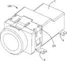
图1是本实用新型电连接器的立体图。Fig. 1 is a perspective view of the electrical connector of the present invention.
图2是图1另一角度的立体图。Fig. 2 is a perspective view from another angle of Fig. 1 .
图3是图1的立体分解图。FIG. 3 is an exploded perspective view of FIG. 1 .
图4是图2的立体分解图。FIG. 4 is an exploded perspective view of FIG. 2 .
【具体实施方式】【Detailed ways】
请参图3,本实用新型电连接器100包括绝缘本体1和固持于绝缘本体1的接地端子2、第一端子3和第二端子4。Referring to FIG. 3 , the
请参图1至图4,绝缘本体1大致呈长方体状,其包括上壁10、与上壁10相对的下壁11、左右壁12、13及前后端面14、15。绝缘本体1从前端面14向前凸伸一呈圆柱状的对接部16。所述绝缘本体1从对接部16向其内部设有可供一对接连接器(未图示)插入的收容腔17,从后端面15向其内部设有与收容腔17相连通的第一、第二收容槽181、182。所述绝缘本体1靠近前端面14处设有一凹陷的收容部19,该收容部19包括设于上壁10的顶壁191及分别设于左右壁12、13的左右侧壁192、193。Referring to FIGS. 1 to 4 , the
第一端子3(即中心端子)收容于绝缘本体1的第一收容槽181内,大体呈圆柱状。该第一端子3包括呈柱状的基部30、由基部30一端延伸出的亦呈柱状的接触部31及由基部30另一端延伸出的固持部32。接触部31悬空于收容腔17内可与对接连接器相电性连接,该接触部31的截面面积小于基部30的截面面积。基部30和固持部32固持于第一收容槽181内,固持部32包括分别向下延伸的第一、第二固持
第二端子4收容于绝缘本体1的第二收容槽182内,大体呈U型。该第二端子4包括固定部40和由固定部弯折延伸的弹
接地端子2组装于绝缘本体1的收容部19,由
接地端子2在基部20的两端与固持部21的交界处分别设有一对肋部24。每对肋部24向外凸起并排列于交界处,所述肋部24的两端分别向基部20和固持部21延伸。当对接连接器插入收容腔17时,弹性接触臂22向上弹性变形,同时基部20与固持部21的交界处受弹性接触臂的影响作为受力点使整个基部20有向上抬起的风险。而肋部24均匀分布于交界处,加强接地端子2的强度,从而使基部20更可靠的贴合于顶壁191上,降低基部20被向上抬起的风险,继而使弹性接触臂22位于正确的连接位置且使接地端子2稳定固持于绝缘本体1内,从而保证接地效果。本实用新型电连接器通过设置肋部以加强接地端子从而降低被抬起的风险,所述肋部除上述实施例所描述的情况外,还可以是其它样态。比如,基部与固持部的交界处可以设置一个或是多个肋部;肋部可继续向基部和固持部延伸;基部的其它受力点亦可设置肋部,等等。当然,还有其它的实施方式,这里不再一一列举。The
所述电连接器的上壁和左壁在靠近后端面处均凹陷102、121,以节省材料和空间。该电连接器通过设置于下壁的凸柱111可将电连接器定位于一电路板上(未图示),又通过分设于四处的第一、第二和第三焊接部焊接固定于电路板上。Both the upper wall and the left wall of the electrical connector are recessed 102, 121 near the rear end surface to save material and space. The electrical connector can be positioned on a circuit board (not shown) through the protruding post 111 arranged on the lower wall, and fixed to the circuit board by welding the first, second and third welding parts arranged in four places. board.
Claims (10)
Translated fromChinese
Priority Applications (1)
| Application Number | Priority Date | Filing Date | Title |
|---|---|---|---|
| CNU2008201854201UCN201285939Y (en) | 2008-09-04 | 2008-09-04 | Electric connector |
Applications Claiming Priority (1)
| Application Number | Priority Date | Filing Date | Title |
|---|---|---|---|
| CNU2008201854201UCN201285939Y (en) | 2008-09-04 | 2008-09-04 | Electric connector |
Publications (1)
| Publication Number | Publication Date |
|---|---|
| CN201285939Ytrue CN201285939Y (en) | 2009-08-05 |
Family
ID=40950910
Family Applications (1)
| Application Number | Title | Priority Date | Filing Date |
|---|---|---|---|
| CNU2008201854201UExpired - Fee RelatedCN201285939Y (en) | 2008-09-04 | 2008-09-04 | Electric connector |
Country Status (1)
| Country | Link |
|---|---|
| CN (1) | CN201285939Y (en) |
Cited By (2)
| Publication number | Priority date | Publication date | Assignee | Title |
|---|---|---|---|---|
| CN107809031A (en)* | 2017-11-21 | 2018-03-16 | 泰州超人汽车电子有限公司 | It is a kind of that there is the binding post for stablizing sheath |
| CN109560409A (en)* | 2017-09-25 | 2019-04-02 | 广濑电机株式会社 | Electric connector and terminal |
- 2008
- 2008-09-04CNCNU2008201854201Upatent/CN201285939Y/ennot_activeExpired - Fee Related
Cited By (3)
| Publication number | Priority date | Publication date | Assignee | Title |
|---|---|---|---|---|
| CN109560409A (en)* | 2017-09-25 | 2019-04-02 | 广濑电机株式会社 | Electric connector and terminal |
| CN109560409B (en)* | 2017-09-25 | 2021-07-27 | 广濑电机株式会社 | Electric connector and terminal |
| CN107809031A (en)* | 2017-11-21 | 2018-03-16 | 泰州超人汽车电子有限公司 | It is a kind of that there is the binding post for stablizing sheath |
Similar Documents
| Publication | Publication Date | Title |
|---|---|---|
| CN201204309Y (en) | electrical connector | |
| CN201029125Y (en) | Cable Connector Assembly | |
| CN202196951U (en) | Plate terminal connector | |
| CN1256530A (en) | Electric connector combination | |
| CN201336452Y (en) | Electric connector | |
| CN201708330U (en) | Electric connector | |
| CN200941505Y (en) | electrical connector | |
| CN203660203U (en) | Switch electric connector | |
| CN201285939Y (en) | Electric connector | |
| CN101677154B (en) | Electric connector | |
| JP3168661U (en) | Electrical connector | |
| CN200986997Y (en) | Electric connector terminal | |
| CN201075432Y (en) | Electric Connector | |
| CN204333362U (en) | Probe connector with cable | |
| CN203466318U (en) | Micro-usb connector | |
| CN201440507U (en) | Electric connector | |
| CN101662089A (en) | Board to board electric connector | |
| CN201285841Y (en) | Electric connector | |
| CN204885710U (en) | electrical connector | |
| CN202076510U (en) | Electrical connectors and electrical connector components | |
| CN2697652Y (en) | Axial connector | |
| CN202856043U (en) | Electric connector | |
| CN201667422U (en) | Electric connector | |
| CN201112619Y (en) | electrical connector | |
| CN2697905Y (en) | Axial cable connector |
Legal Events
| Date | Code | Title | Description |
|---|---|---|---|
| C14 | Grant of patent or utility model | ||
| GR01 | Patent grant | ||
| C17 | Cessation of patent right | ||
| CF01 | Termination of patent right due to non-payment of annual fee | Granted publication date:20090805 Termination date:20100904 |