CN201267069Y - Portable electronic apparatus - Google Patents
Portable electronic apparatusDownload PDFInfo
- Publication number
- CN201267069Y CN201267069YCNU2008201265245UCN200820126524UCN201267069YCN 201267069 YCN201267069 YCN 201267069YCN U2008201265245 UCNU2008201265245 UCN U2008201265245UCN 200820126524 UCN200820126524 UCN 200820126524UCN 201267069 YCN201267069 YCN 201267069Y
- Authority
- CN
- China
- Prior art keywords
- bracing
- strutting arrangement
- portable electric
- electric appts
- casing ontology
- Prior art date
- Legal status (The legal status is an assumption and is not a legal conclusion. Google has not performed a legal analysis and makes no representation as to the accuracy of the status listed.)
- Expired - Fee Related
Links
Images


Classifications
- H—ELECTRICITY
- H04—ELECTRIC COMMUNICATION TECHNIQUE
- H04M—TELEPHONIC COMMUNICATION
- H04M1/00—Substation equipment, e.g. for use by subscribers
- H04M1/02—Constructional features of telephone sets
- H04M1/0297—Telephone sets adapted to be mounted on a desk or on a wall
- G—PHYSICS
- G06—COMPUTING OR CALCULATING; COUNTING
- G06F—ELECTRIC DIGITAL DATA PROCESSING
- G06F1/00—Details not covered by groups G06F3/00 - G06F13/00 and G06F21/00
- G06F1/16—Constructional details or arrangements
- G06F1/1613—Constructional details or arrangements for portable computers
- G06F1/1626—Constructional details or arrangements for portable computers with a single-body enclosure integrating a flat display, e.g. Personal Digital Assistants [PDAs]
- G—PHYSICS
- G06—COMPUTING OR CALCULATING; COUNTING
- G06F—ELECTRIC DIGITAL DATA PROCESSING
- G06F1/00—Details not covered by groups G06F3/00 - G06F13/00 and G06F21/00
- G06F1/16—Constructional details or arrangements
- G06F1/1613—Constructional details or arrangements for portable computers
- G06F1/1633—Constructional details or arrangements of portable computers not specific to the type of enclosures covered by groups G06F1/1615 - G06F1/1626
- G06F1/1656—Details related to functional adaptations of the enclosure, e.g. to provide protection against EMI, shock, water, or to host detachable peripherals like a mouse or removable expansions units like PCMCIA cards, or to provide access to internal components for maintenance or to removable storage supports like CDs or DVDs, or to mechanically mount accessories
- G06F1/166—Details related to functional adaptations of the enclosure, e.g. to provide protection against EMI, shock, water, or to host detachable peripherals like a mouse or removable expansions units like PCMCIA cards, or to provide access to internal components for maintenance or to removable storage supports like CDs or DVDs, or to mechanically mount accessories related to integrated arrangements for adjusting the position of the main body with respect to the supporting surface, e.g. legs for adjusting the tilt angle
- H—ELECTRICITY
- H04—ELECTRIC COMMUNICATION TECHNIQUE
- H04M—TELEPHONIC COMMUNICATION
- H04M1/00—Substation equipment, e.g. for use by subscribers
- H04M1/02—Constructional features of telephone sets
- H04M1/0202—Portable telephone sets, e.g. cordless phones, mobile phones or bar type handsets
- H04M1/0206—Portable telephones comprising a plurality of mechanically joined movable body parts, e.g. hinged housings
- H04M1/0208—Portable telephones comprising a plurality of mechanically joined movable body parts, e.g. hinged housings characterized by the relative motions of the body parts
- H04M1/0214—Foldable telephones, i.e. with body parts pivoting to an open position around an axis parallel to the plane they define in closed position
- H04M1/0216—Foldable in one direction, i.e. using a one degree of freedom hinge
- H—ELECTRICITY
- H04—ELECTRIC COMMUNICATION TECHNIQUE
- H04M—TELEPHONIC COMMUNICATION
- H04M1/00—Substation equipment, e.g. for use by subscribers
- H04M1/02—Constructional features of telephone sets
- H04M1/04—Supports for telephone transmitters or receivers
Landscapes
- Engineering & Computer Science (AREA)
- Computer Hardware Design (AREA)
- Theoretical Computer Science (AREA)
- General Engineering & Computer Science (AREA)
- Human Computer Interaction (AREA)
- Physics & Mathematics (AREA)
- General Physics & Mathematics (AREA)
- Signal Processing (AREA)
- Telephone Set Structure (AREA)
Abstract
Translated fromChineseDescription
Translated fromChinese技术领域technical field
本实用新型涉及一种便携式电子设备。The utility model relates to a portable electronic device.
背景技术Background technique
当今社会,各种各样的便携式电子设备如春笋般出现在市场和人们的生活中,在功能表现上,也不单单局限于一种单一功能,例如手机早已不再是简单的通话工具,随着通讯技术的发展,手机的娱乐和商务助理等众多功能都已经实现,极大的方便了人们的生活,提高了生活水平和工作质量。便携式电子设备,如手机、电子数字助理(PDA),现多具备拍照、摄像、视频播放、视频通话等功能。In today's society, a variety of portable electronic devices have sprung up in the market and people's lives. In terms of functional performance, they are not limited to a single function. For example, mobile phones are no longer simple communication tools. With the development of communication technology, many functions such as entertainment and business assistants of mobile phones have been realized, which greatly facilitates people's life and improves living standards and work quality. Portable electronic devices, such as mobile phones and electronic digital assistants (PDAs), now mostly have functions such as taking photos, video recordings, video playback, and video calls.
但是,当前的便携式电子设备在进行语音或者视频通话、或者是进行视频播放等时,没有办法固定便携式电子设备的位置和摆放状态,这样使用者就必须一直用手握着该设备来保持直立姿态,给使用者带来了不便。However, when the current portable electronic devices are making voice or video calls, or playing video, etc., there is no way to fix the position and placement of the portable electronic devices, so the user must always hold the device with his hand to keep it upright. attitude, which brings inconvenience to the user.
中国专利CN2935654Y公开了一种带有支撑结构的手机,包括机壳本体和支撑结构。机壳本体和支撑结构都具有一连接部,从而可以使机壳本体和支撑结构连接,当手机撑立时,支撑结构以连接部的支点展开与机壳本体夹一角度,从而使手机利用机壳本体和支撑结构支撑站立。但是这种手机的支撑装置只能用手动打开支撑结构到一位置,无法自动打开。这种手机的支撑装置使用一段时间后,支撑结构和手机机壳本体之间的连接部容易松动,从而支撑结构可能会以连接部的支点转动,不再能保持稳定的角度使手机稳固地站立,或不再与机壳背面紧密结合而随时展开支撑结构,造成不便。Chinese patent CN2935654Y discloses a mobile phone with a supporting structure, including a casing body and a supporting structure. Both the casing body and the supporting structure have a connecting portion, so that the casing body and the supporting structure can be connected. When the mobile phone is stood upright, the supporting structure is unfolded at an angle with the casing body at the fulcrum of the connecting portion, so that the mobile phone can use the casing The body and support structure supports standing. But the support device of this mobile phone can only be manually opened to a position with the support structure, and cannot be opened automatically. After the supporting device of this kind of mobile phone is used for a period of time, the connection between the supporting structure and the main body of the mobile phone case is easy to loosen, so that the supporting structure may rotate at the fulcrum of the connecting part, and can no longer maintain a stable angle so that the mobile phone can stand firmly , or no longer tightly combined with the back of the casing to expand the support structure at any time, causing inconvenience.
实用新型内容Utility model content
本实用新型针对现有技术中只能手动打开支撑结构的问题,提供了一种可自动打开支撑装置的便携式电子设备。The utility model aims at the problem that the support structure can only be opened manually in the prior art, and provides a portable electronic device which can automatically open the support device.
本实用新型提供了一种便携式电子设备,包括机壳本体和支撑装置,支撑装置转动连接到机壳本体的一面;其中,该便携式电子设备还包括自动打开装置,该装置使得支撑装置能自动转动到与机壳本体之间成一角度的位置并定位在该位置。The utility model provides a portable electronic device, which includes a casing body and a supporting device, and the supporting device is rotatably connected to one side of the casing body; wherein, the portable electronic device also includes an automatic opening device, which enables the supporting device to automatically rotate to and position at an angle to the body of the enclosure.
本实用新型提供的便携式电子设备由于采用了自动打开装置,使得机壳本体与支撑装置之间的连接是可自动打开的转动连接,所以相比于现有技术,该便携式电子设备不需要手动人工打开支撑装置,而可以自动打开到一角度,使用更加方便,从而保证支撑装置打开后与机壳本体保持稳定的角度,使得手机可以稳定的站立,以及保证支撑装置闭合时,可以与及壳背面紧密地结合,提高了便携电子设备的支撑装置的耐用性、方便性。The portable electronic equipment provided by the utility model adopts an automatic opening device, so that the connection between the casing body and the supporting device is a rotating connection that can be automatically opened, so compared with the prior art, the portable electronic equipment does not require manual labor. When the support device is opened, it can be automatically opened to an angle, which is more convenient to use, so as to ensure that the support device maintains a stable angle with the case body after opening, so that the mobile phone can stand stably, and when the support device is closed, it can be connected to the back of the case The tight combination improves the durability and convenience of the supporting device of the portable electronic equipment.
附图说明Description of drawings
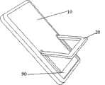
图1是本实用新型的便携式电子设备其支撑装置闭合时的立体图;Fig. 1 is the three-dimensional view when its supporting device of portable electronic equipment of the present invention is closed;
图2是本实用新型的便携式电子设备其支撑装置打开时的立体图;Fig. 2 is a perspective view when the supporting device of the portable electronic device of the present invention is opened;
图3是根据本实用新型的一个实施方式的便携式电子设备除去机壳前面壳体后的内部结构正视图;3 is a front view of the internal structure of the portable electronic device according to an embodiment of the present invention after removing the front shell of the casing;
图4是根据本实用新型的一个实施方式的便携式电子设备除去机壳前面壳体后的内部结构立体图;4 is a perspective view of the internal structure of the portable electronic device according to an embodiment of the present invention after removing the front shell of the casing;
图5是根据本实用新型的另一个实施方式的便携式电子设备除去机壳前面壳体后的内部结构立体图;5 is a perspective view of the internal structure of the portable electronic device according to another embodiment of the present invention after removing the front shell of the casing;
图6是根据本实用新型的另一个实施方式的便携式电子设备除去机壳前面壳体后的内部结构正视图;Fig. 6 is a front view of the internal structure of the portable electronic device according to another embodiment of the utility model after removing the front shell of the casing;
图7是根据本实用新型的另一个实施方式的便携式电子设备的自动打开装置的透视图。Fig. 7 is a perspective view of an automatic opening device of a portable electronic device according to another embodiment of the present invention.
具体实施方式Detailed ways
下面结合附图对本实用新型作进一步的说明。Below in conjunction with accompanying drawing, the utility model is further described.
图1、图2分别是根据本实用新型的便携式电子设备的一种实施方式其支撑装置闭合和打开时的立体图。参考图1、图2所示,本实用新型提供的便携式电子设备,包括机壳本体10和支撑装置20,支撑装置20转动连接到机壳本体10的一面;其中,该便携式电子设备还包括自动打开装置(图1、2中未图示),该装置使得支撑装置20能自动转动到与机壳本体之间成一角度的位置并定位在该位置。FIG. 1 and FIG. 2 are perspective views of a portable electronic device according to an embodiment of the present invention when its supporting device is closed and opened. Referring to Fig. 1 and Fig. 2, the portable electronic equipment provided by the utility model includes a
所述角度的范围优选为30-90度,以便于直立或侧立。该角度可以为一个固定角度,即每次支撑装置20都自动打开相同的角度,该角度也可以为可变的角度,即每次可以由用户根据需要选择打开为不同的角度。The range of the angle is preferably 30-90 degrees, so as to stand upright or sideways. The angle can be a fixed angle, that is, the
上述角度的设置可以通过本领域技术人员所熟知的各种限位装置实现,例如图1、2所示,设置机壳本体10和支撑装置20相接的部分的夹角为预定的角度,这样当支撑装置20旋转到一角度时两个斜面相接触可以阻止支撑装置20进一步转动。另外,也可以是绳索、折叠连杆等等。The setting of the above-mentioned angle can be realized by various limiting devices well known to those skilled in the art. For example, as shown in FIGS. When the
机壳本体10可以为各种结构,如直板式、翻盖式、滑盖式、旋盖式等等,也可以采用各种材料,如金属、塑料、树脂等等,均不影响本实用新型的技术方案的实施。The
机壳本体10的一面可以具有显示屏,此时支撑装置20优选连接到机壳本体10上与显示屏相对的一面。One side of the
所述支撑装置20可以为一个或多个支板或中空支架,形状不作特别限定,以能支撑住机壳本体10为限,例如四边形中空支架。优选情况下,连接有支撑装置20的机壳本体10的一面还可以设置有与支撑装置20的大小、形状相配合的凹槽90,如图2所示,使得所述支撑装置20闭合时可以置于该凹槽90内。The
所述机壳本体10与支撑装置20之间转动连接的方式可以为多种形式,例如通过孔轴转动连接、合页转动连接等等。如图3、4所示为一种实施方式,采用了滑槽和转轴的转动连接方式。根据这一优选实施方式,该便携式电子设备还包括滑槽(未图示)和转轴31,其中所述滑槽位于机壳本体10和支撑装置20中的一者上,转轴31位于滑槽内与滑槽转动配合,并与机壳本体10和支撑装置20中的另一者固定连接。在图3、4的示例中,滑槽设置在机壳本体10上,转轴31设置在支撑装置20上。当然,滑槽也可以设置在支撑装置20上,转轴31设置在机壳本体10上。滑槽可以为不封闭的凹槽,以便于转轴31从滑槽中取出。The rotational connection between the
其中本实用新型中提到的自动打开装置可以通过多种方式来实现,下面具体介绍自动打开装置的各种实施方式。Among them, the automatic opening device mentioned in the utility model can be realized in various ways, and various implementation modes of the automatic opening device will be introduced in detail below.
自动打开装置的第一种实施方式是通过弹性部件来实现自动打开。弹性部件可以有很多种,例如弹簧、簧片等等。The first embodiment of the automatic opening device realizes automatic opening through elastic components. There are many kinds of elastic components, such as springs, reeds and so on.
所述自动打开装置包括一个或多个弹簧,弹簧的两端分别固定在机壳本体10或支撑装置20上或紧压在机壳本体10与支撑装置20之间,用于利用弹簧的弹力自动弹开所述支撑装置20到一位置,另外,由于弹簧自身具有中间稳定状态,所以当弹簧保持在中间稳定状态时,支撑装置20可以保持在此时的位置处,也就是说在这种实施方式下可以不设置上述的限位装置以保持电子设备的稳定站立。所述弹簧可以为一个或多个,在图3、图4中以两个作为示例。The automatic opening device includes one or more springs, and the two ends of the springs are respectively fixed on the
所述弹簧可以为扭转弹簧、压缩弹簧或者弹片弹簧。图3、4所示为扭转弹簧40,根据图3、图4的实施方式,所述扭转弹簧40可以套在转轴31上,前脚42、后脚43分别连接或者顶住机壳本体10和支撑装置20,这样支撑装置20在扭转弹簧40的弹力下可以以转轴31为中心轴旋转弹开一个角度。The spring may be a torsion spring, a compression spring or a leaf spring. Figures 3 and 4 show a
根据优选的实施方式,自动打开装置还可以包括支撑装置夹持部件,例如弹簧卡扣或支架卡,用于当支撑装置20闭合时夹持住支撑装置20。例如,弹簧卡扣可以设置在凹槽90内,或者安在支撑装置20上,当所述支撑装置20闭合时,通过该弹簧卡扣将所述支撑装置20卡住在所述凹槽90内,以防止支撑装置20打开,而拨动该弹簧卡扣,就可以松开所述支撑装置20,使得该支撑装置20在弹簧40的弹力作用下自动弹开。又例如,支架卡适用于支撑装置20为中空支架的情况,支架卡可以设置在凹槽90中,使得所述支撑装置20闭合时,中空支架被该支架卡卡住,打开该支撑装置20时,用手推动该支撑装置20使得中空支架离开所述支架卡,从而实现所支撑装置20在弹簧40的弹力下的自动弹开。According to a preferred embodiment, the automatic opening device may further include a clamping part of the supporting device, such as a spring buckle or a bracket clip, for clamping the supporting
自动打开装置的第二种实施方式是通过电力驱动部件来实现自动打开。电力驱动部件可以有很多种,例如电机、马达等等,这样通过电力驱动部件来推动支撑装置20自动打开。The second embodiment of the automatic opening device is to realize the automatic opening by means of electric drive components. There can be many kinds of electric drive components, such as motors, motors, etc., so that the
所述自动打开装置可以通过电力驱动部件和传动装置实现。传动装置可以为齿轮传动,通过电机带动主动齿轮转动,并与支撑装置上装有的从动齿轮相啮合,从而使得支撑装置打开。所述传动装置也可以是本领域技术人员所知的其它装置。Said automatic opening means can be realized by means of electric drive components and transmissions. The transmission device can be a gear transmission, the driving gear is driven by the motor to rotate, and meshes with the driven gear mounted on the supporting device, so that the supporting device is opened. The transmission device may also be other devices known to those skilled in the art.
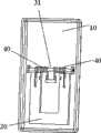
如图5、图6、图7为一种实施方式。根据这种实施方式所述自动打开装置包括马达50、传动装置和马达控制装置,马达50与传动装置机械连接,传动装置与支撑装置20机械连接,马达控制装置与马达50电连接。其中马达50具有转盘,所述传动装置包括转轮51、连杆60以及扭转弹簧40,所述马达50的转盘的盘面上具有拨杆53,该拨杆53与所述转轮51一侧的轮缘相接触,所述转轮51另一侧的轮缘与连杆60相接触,所述连杆60固定在所述支撑装置20的与机壳本体10相连的一端,所述扭转弹簧40套在所述转轴31上,该扭转弹簧40的两端分别与外壳本体10和支撑装置20相接触且该扭转弹簧40处于压缩状态。当所述马达50启动而转动时,所述转轮51在拨杆53的驱动下向下运动,该转轮51将推动连杆60向下运动,由于连杆60与支撑装置20固定成一角度连接,从而连杆60带动所述支撑装置20转动,使该支撑装置20打开。Fig. 5, Fig. 6, Fig. 7 is an embodiment. According to this embodiment, the automatic opening device includes a
通过马达控制装置控制马达50的开启和停止,当要打开支撑装置20时,马达控制装置开启马达50使其从初始位置处开始转动,马达50上的拨杆53将推动转轮51,从而推动连杆60向下运动,进而带动所述支撑装置20使其打开。通过马达控制装置令马达50停止,即可以使所述支撑装置20打开到一定角度,从而实现了该便携式电子设备的支撑装置20的自动打开。当拨杆旋转至最低处时使马达50停止转动,此时支撑装置20打开至最大角度并停止在该角度。再次控制该马达50使其继续转动,所述马达上的拨杆53离开最低位置,所述支撑装置20在扭转弹簧40的弹力的作用下趋向闭合,当马达50回到初始位置实现复位时,所述支撑装置20及连杆60推动转轮51复位,完成一个动作循环。The start and stop of the
上述马达控制装置可以由控制电路实现,也可以通过便携电子设备内部的软件实现,设计软件程序可以使得马达在不同位置停止和开启,从而实现所述支撑装置根据用户需要打开不同角度,或者只打开一个固定的角度。The above-mentioned motor control device can be realized by a control circuit, or by the software inside the portable electronic device. The software program can be designed to make the motor stop and start at different positions, so that the support device can be opened at different angles according to user needs, or only open a fixed angle.
自动打开装置的第三种实施方式是通过磁性部件来实现自动打开。磁性部件也可以有很多种方式,例如磁体、电磁体等等。The third embodiment of the automatic opening device is to realize the automatic opening by means of magnetic components. Magnetic components can also come in many forms, such as magnets, electromagnets, and so on.
根据一种实施方式,自动打开装置包括一对磁体,分别设置在机壳本体10和支撑装置20上,其中至少一个磁体为磁极可变的磁体。当该对磁体相对的一面为不同磁极时,机壳本体10与支撑装置20相互排斥,从而可以自动打开,而当该对磁体相对的一面为相同磁极时,机壳本体10与支撑装置20相互吸引,还可以自动关闭。According to one embodiment, the automatic opening device includes a pair of magnets, which are respectively arranged on the
上述安装在机壳本体10和所述支撑装置20上的一对磁体可以是其中一个的磁极不可变,只控制改变另一个磁体的磁极;也可以两个磁体的磁极都可变,通过控制分别改变两个磁性部件的磁极。The above-mentioned pair of magnets installed on the
其中设置在机壳本体10上的磁体优选为电磁铁,这样可以很方便地通过改变流入电磁铁中线圈的电流方向,从而改变电磁铁的磁极。因此,在这种情况下,该自动打开装置还包括磁性控制器,与电磁铁中的线圈电连接,用以控制电磁铁中线圈中的电流方向。The magnet disposed on the
优选情况下,为了减少打开和关闭支撑装置20时对机壳本体10的冲击力,排斥力和吸引力的大小是可以通过调节电流的大小来控制的,因此磁性控制器还用以控制电磁铁中线圈中的电流大小。Preferably, in order to reduce the impact force on the
上述磁性控制器可以通过该便携式电子设备中的应用程序实现。The above-mentioned magnetic controller can be realized through the application program in the portable electronic device.
能够应用本实用新型的便携式电子设备可以有很多种,例如手机、PDA、MP3、MP4等数字播放器、游戏机、电子词典、平板式笔记本电脑等等。There are many kinds of portable electronic devices that can apply the utility model, such as digital players such as mobile phones, PDA, MP3, MP4, game consoles, electronic dictionaries, tablet notebook computers and the like.
Claims (11)
Priority Applications (2)
| Application Number | Priority Date | Filing Date | Title |
|---|---|---|---|
| CNU2008201265245UCN201267069Y (en) | 2008-06-27 | 2008-06-27 | Portable electronic apparatus |
| US12/482,384US20090321609A1 (en) | 2008-06-27 | 2009-06-10 | Portable Electronics |
Applications Claiming Priority (1)
| Application Number | Priority Date | Filing Date | Title |
|---|---|---|---|
| CNU2008201265245UCN201267069Y (en) | 2008-06-27 | 2008-06-27 | Portable electronic apparatus |
Publications (1)
| Publication Number | Publication Date |
|---|---|
| CN201267069Ytrue CN201267069Y (en) | 2009-07-01 |
Family
ID=40833441
Family Applications (1)
| Application Number | Title | Priority Date | Filing Date |
|---|---|---|---|
| CNU2008201265245UExpired - Fee RelatedCN201267069Y (en) | 2008-06-27 | 2008-06-27 | Portable electronic apparatus |
Country Status (2)
| Country | Link |
|---|---|
| US (1) | US20090321609A1 (en) |
| CN (1) | CN201267069Y (en) |
Cited By (20)
| Publication number | Priority date | Publication date | Assignee | Title |
|---|---|---|---|---|
| CN102022608A (en)* | 2010-11-17 | 2011-04-20 | 鸿富锦精密工业(深圳)有限公司 | Electronic device with bracket |
| CN102297328A (en)* | 2010-06-22 | 2011-12-28 | 昆达电脑科技(昆山)有限公司 | Folding horse |
| CN102523320A (en)* | 2011-12-27 | 2012-06-27 | 惠州Tcl移动通信有限公司 | Support and mobile terminal |
| CN102655536A (en)* | 2011-03-02 | 2012-09-05 | 三星电子株式会社 | Slim-type cradling apparatus for portable terminal |
| CN102715721A (en)* | 2012-06-15 | 2012-10-10 | 鸿富锦精密工业(深圳)有限公司 | Protective casing with support |
| CN103677121A (en)* | 2012-09-11 | 2014-03-26 | 罗技欧洲公司 | Protective cover for a tablet computer |
| CN103777705A (en)* | 2014-03-03 | 2014-05-07 | 联想(北京)有限公司 | Braking device |
| CN104063012A (en)* | 2013-03-20 | 2014-09-24 | 联想(北京)有限公司 | Electronic equipment |
| WO2015109877A1 (en)* | 2014-01-21 | 2015-07-30 | 李铁 | Side-supported smartphone |
| CN105334910A (en)* | 2014-06-24 | 2016-02-17 | 联想(北京)有限公司 | Magnetic control method and device |
| CN106287124A (en)* | 2015-06-29 | 2017-01-04 | 联想(北京)有限公司 | A kind of support means and electronic equipment |
| CN106879217A (en)* | 2017-03-31 | 2017-06-20 | 湖南长城信息金融设备有限责任公司 | Overturning-preventing tray support structure and its rack of application |
| CN107453418A (en)* | 2017-06-23 | 2017-12-08 | 深圳天珑无线科技有限公司 | The device and its mobile terminal of the charging connector of automatic spring charging device |
| CN108953906A (en)* | 2018-06-19 | 2018-12-07 | 芜湖华特电子科技有限公司 | A kind of industrial display with angle adjustment device |
| CN109620650A (en)* | 2018-10-25 | 2019-04-16 | 张节伟 | A kind of leg surgery patient intelligent rehabilitation bracket |
| CN110392133A (en)* | 2018-04-20 | 2019-10-29 | Oppo广东移动通信有限公司 | an electronic device |
| CN114096936A (en)* | 2019-07-03 | 2022-02-25 | 华为技术有限公司 | Enhancing virtual communication with mobile communication devices |
| CN114710896A (en)* | 2022-03-25 | 2022-07-05 | 乐歌人体工学科技股份有限公司 | Shell structure of portable intelligent terminal |
| CN116928501A (en)* | 2022-04-12 | 2023-10-24 | 北京小米移动软件有限公司 | Support device, electronic equipment accessory, electronic equipment and control method |
| CN118151721A (en)* | 2024-01-30 | 2024-06-07 | 华为技术有限公司 | Electronic equipment |
Families Citing this family (28)
| Publication number | Priority date | Publication date | Assignee | Title |
|---|---|---|---|---|
| US20110013351A1 (en)* | 2009-07-20 | 2011-01-20 | Mobile Monitor Technologies, Llc | Portable monitor |
| CN101998784A (en)* | 2009-08-21 | 2011-03-30 | 鸿富锦精密工业(深圳)有限公司 | Portable electronic device |
| CN102563304B (en)* | 2010-12-23 | 2015-11-25 | 富泰华工业(深圳)有限公司 | Electronic device support and the electronic equipment with electronic device support |
| CN103121547A (en)* | 2011-11-21 | 2013-05-29 | 深圳富泰宏精密工业有限公司 | Multifunctional protective shell |
| TWI498709B (en)* | 2012-06-18 | 2015-09-01 | Wistron Corp | Electronic device and supporting mechanism thereof |
| TWI602047B (en)* | 2015-02-06 | 2017-10-11 | 仁寶電腦工業股份有限公司 | Electronic device having stand module |
| US9823704B2 (en)* | 2015-08-14 | 2017-11-21 | Urban Armor Gear, Llc | Protective case for a computing device with adjustable stand |
| WO2017044102A1 (en)* | 2015-09-10 | 2017-03-16 | Hewlett-Packard Development Company, L.P. | Kickstands |
| TWI588398B (en)* | 2015-12-30 | 2017-06-21 | 華碩電腦股份有限公司 | Electronic device and electronic system |
| CN108700911A (en)* | 2016-03-11 | 2018-10-23 | 惠普发展公司,有限责任合伙企业 | Holder for computing device |
| GB201608605D0 (en)* | 2016-05-16 | 2016-06-29 | Hu Do Ltd | Device |
| TWM540304U (en)* | 2016-05-17 | 2017-04-21 | Asustek Comp Inc | Tablet type electronic device |
| CN108287593B (en)* | 2017-01-09 | 2020-10-16 | 宏碁股份有限公司 | Portable electronic device |
| US20190056765A1 (en)* | 2017-08-16 | 2019-02-21 | Deonna Harris | Electronic Scheduling Assembly |
| CN108573583B (en)* | 2018-03-08 | 2021-01-29 | 陈静 | Intelligence POS machine with waterproof and function that is in light |
| US10455067B1 (en)* | 2018-09-13 | 2019-10-22 | Plantronics, Inc. | Holder for a mobile computing device |
| USD917465S1 (en)* | 2018-10-19 | 2021-04-27 | Yealink (Xiamen) Network Technology Co., Ltd. | Control terminal with display |
| CN112956173B (en)* | 2018-12-29 | 2023-04-25 | Oppo广东移动通信有限公司 | Mobile terminal |
| CN210405375U (en)* | 2018-12-29 | 2020-04-24 | Oppo广东移动通信有限公司 | Mobile phone and its host |
| USD893498S1 (en) | 2019-01-09 | 2020-08-18 | Urban Armor Gear, Llc | Case for a computing device |
| JP1641986S (en)* | 2019-04-15 | 2019-09-24 | ||
| JP7319323B2 (en)* | 2021-05-28 | 2023-08-01 | 任天堂株式会社 | Electronics and equipment holding systems |
| JP1706159S (en)* | 2021-07-14 | 2022-01-27 | Portable monitor | |
| USD984438S1 (en)* | 2021-07-21 | 2023-04-25 | Shenzhen Mide Innovation Technology Co., Ltd. | Portable display |
| USD984437S1 (en)* | 2021-07-21 | 2023-04-25 | Shenzhen Mide Innovation Technology Co., Ltd. | Portable display |
| USD990466S1 (en)* | 2021-07-21 | 2023-06-27 | Shenzhen Mide Innovation Technology Co., Ltd. | Portable display |
| USD994664S1 (en) | 2021-11-18 | 2023-08-08 | Elo Touch Solutions, Inc. | Electronic device |
| USD1055038S1 (en)* | 2023-02-22 | 2024-12-24 | Bryan D. Jones | Phone case kick stand |
Family Cites Families (10)
| Publication number | Priority date | Publication date | Assignee | Title |
|---|---|---|---|---|
| US6003831A (en)* | 1998-02-26 | 1999-12-21 | Tektronix, Inc. | Instrument with stand and hook |
| DE10107041B4 (en)* | 2001-02-15 | 2006-08-03 | Agilent Technologies, Inc. (n.d.Ges.d.Staates Delaware), Palo Alto | Support device for a portable device |
| US7011285B2 (en)* | 2003-07-02 | 2006-03-14 | Inventec Corporation | Modular stand structure |
| CN2742724Y (en)* | 2004-05-26 | 2005-11-23 | 广州矽金塔电子有限公司 | Portable electronic product with support rack |
| JP3112839U (en)* | 2005-05-26 | 2005-08-25 | 船井電機株式会社 | Display device |
| US7293747B2 (en)* | 2005-08-03 | 2007-11-13 | Inventec Corporation | Display moveable in two dimensions |
| TW200844358A (en)* | 2007-05-11 | 2008-11-16 | Jarllytec Co Ltd | Height adjusting stand |
| CN101471144B (en)* | 2007-12-28 | 2013-06-05 | 鸿富锦精密工业(深圳)有限公司 | Regulating mechanism for display equipment |
| US7922133B2 (en)* | 2008-09-12 | 2011-04-12 | Shin Zu Shing Co., Ltd. | Flat panel display support |
| CN101737606B (en)* | 2008-11-17 | 2012-07-18 | 鸿富锦精密工业(深圳)有限公司 | Elevator mechanism and four-bar linkage structure thereof |
- 2008
- 2008-06-27CNCNU2008201265245Upatent/CN201267069Y/ennot_activeExpired - Fee Related
- 2009
- 2009-06-10USUS12/482,384patent/US20090321609A1/ennot_activeAbandoned
Cited By (31)
| Publication number | Priority date | Publication date | Assignee | Title |
|---|---|---|---|---|
| CN102297328A (en)* | 2010-06-22 | 2011-12-28 | 昆达电脑科技(昆山)有限公司 | Folding horse |
| CN102022608A (en)* | 2010-11-17 | 2011-04-20 | 鸿富锦精密工业(深圳)有限公司 | Electronic device with bracket |
| CN102022608B (en)* | 2010-11-17 | 2013-10-09 | 鸿富锦精密工业(深圳)有限公司 | Electronic device with stand |
| CN102655536A (en)* | 2011-03-02 | 2012-09-05 | 三星电子株式会社 | Slim-type cradling apparatus for portable terminal |
| CN102655536B (en)* | 2011-03-02 | 2016-12-07 | 三星电子株式会社 | Slim type support unit for portable terminal |
| CN102523320B (en)* | 2011-12-27 | 2014-11-05 | 惠州Tcl移动通信有限公司 | Support and mobile terminal |
| CN102523320A (en)* | 2011-12-27 | 2012-06-27 | 惠州Tcl移动通信有限公司 | Support and mobile terminal |
| CN102715721A (en)* | 2012-06-15 | 2012-10-10 | 鸿富锦精密工业(深圳)有限公司 | Protective casing with support |
| CN103677121A (en)* | 2012-09-11 | 2014-03-26 | 罗技欧洲公司 | Protective cover for a tablet computer |
| CN104063012A (en)* | 2013-03-20 | 2014-09-24 | 联想(北京)有限公司 | Electronic equipment |
| CN104063012B (en)* | 2013-03-20 | 2018-08-10 | 联想(北京)有限公司 | A kind of electronic equipment |
| WO2015109877A1 (en)* | 2014-01-21 | 2015-07-30 | 李铁 | Side-supported smartphone |
| CN103777705A (en)* | 2014-03-03 | 2014-05-07 | 联想(北京)有限公司 | Braking device |
| CN105334910A (en)* | 2014-06-24 | 2016-02-17 | 联想(北京)有限公司 | Magnetic control method and device |
| CN105334910B (en)* | 2014-06-24 | 2019-03-29 | 联想(北京)有限公司 | A kind of magnetic force control method and device |
| CN106287124A (en)* | 2015-06-29 | 2017-01-04 | 联想(北京)有限公司 | A kind of support means and electronic equipment |
| CN106287124B (en)* | 2015-06-29 | 2019-01-15 | 联想(北京)有限公司 | A kind of support device and electronic equipment |
| CN106879217A (en)* | 2017-03-31 | 2017-06-20 | 湖南长城信息金融设备有限责任公司 | Overturning-preventing tray support structure and its rack of application |
| CN106879217B (en)* | 2017-03-31 | 2024-02-13 | 长城信息股份有限公司 | Anti-toppling tray supporting structure and cabinet applying same |
| CN107453418A (en)* | 2017-06-23 | 2017-12-08 | 深圳天珑无线科技有限公司 | The device and its mobile terminal of the charging connector of automatic spring charging device |
| CN110392133A (en)* | 2018-04-20 | 2019-10-29 | Oppo广东移动通信有限公司 | an electronic device |
| CN110392133B (en)* | 2018-04-20 | 2021-07-27 | Oppo广东移动通信有限公司 | an electronic device |
| CN108953906A (en)* | 2018-06-19 | 2018-12-07 | 芜湖华特电子科技有限公司 | A kind of industrial display with angle adjustment device |
| CN109620650A (en)* | 2018-10-25 | 2019-04-16 | 张节伟 | A kind of leg surgery patient intelligent rehabilitation bracket |
| CN114096936A (en)* | 2019-07-03 | 2022-02-25 | 华为技术有限公司 | Enhancing virtual communication with mobile communication devices |
| CN114096936B (en)* | 2019-07-03 | 2024-11-29 | 华为技术有限公司 | Enhancing virtual communication with mobile communication devices |
| CN114710896A (en)* | 2022-03-25 | 2022-07-05 | 乐歌人体工学科技股份有限公司 | Shell structure of portable intelligent terminal |
| CN114710896B (en)* | 2022-03-25 | 2023-10-27 | 乐歌人体工学科技股份有限公司 | Housing structure of portable smart terminal |
| CN116928501A (en)* | 2022-04-12 | 2023-10-24 | 北京小米移动软件有限公司 | Support device, electronic equipment accessory, electronic equipment and control method |
| CN118151721A (en)* | 2024-01-30 | 2024-06-07 | 华为技术有限公司 | Electronic equipment |
| WO2025161435A1 (en)* | 2024-01-30 | 2025-08-07 | 华为技术有限公司 | Electronic device |
Also Published As
| Publication number | Publication date |
|---|---|
| US20090321609A1 (en) | 2009-12-31 |
Similar Documents
| Publication | Publication Date | Title |
|---|---|---|
| CN201267069Y (en) | Portable electronic apparatus | |
| EP1926290B1 (en) | Swing hinge device for a portable terminal | |
| JP5473773B2 (en) | Portable electronic device | |
| CN113932133B (en) | Foldable stand and electronic equipment | |
| WO2006026035A1 (en) | Slidable and foldable electronic device and corresponding method | |
| CN110891222B (en) | Headphone charging box and Bluetooth headset components | |
| US8078238B2 (en) | Electronic device | |
| US20060154619A1 (en) | Semi-automatic swing device for a mobile terminal | |
| CN110166655B (en) | Electronic device | |
| CN201781710U (en) | Portable electronic device | |
| CN111654564A (en) | Screen components and electronic equipment | |
| CN200976610Y (en) | Mobile phones having rotary camera | |
| CN210979102U (en) | Electronic device support | |
| CN217010926U (en) | Cell phone stand is inhaled to magnetism that area rotated and accomodate | |
| CN112203001A (en) | Terminal device | |
| CN210781280U (en) | Earphone charging box and Bluetooth earphone assembly | |
| CN116712722A (en) | Game paddle | |
| TW201128355A (en) | Slide-type electronic device | |
| CN108076170A (en) | A kind of supporting mechanism and mobile terminal | |
| CN111765353B (en) | A multi-angle flip support mechanism and wireless charging stand | |
| CN201730956U (en) | Torsion variable hinge | |
| TWI489849B (en) | Electronic device | |
| CN211551068U (en) | A folding support for intelligent terminal | |
| JP2011139422A (en) | Slide type electronic device | |
| CN216291056U (en) | Electronic device case |
Legal Events
| Date | Code | Title | Description |
|---|---|---|---|
| C14 | Grant of patent or utility model | ||
| GR01 | Patent grant | ||
| CF01 | Termination of patent right due to non-payment of annual fee | Granted publication date:20090701 Termination date:20160627 | |
| CF01 | Termination of patent right due to non-payment of annual fee |