CN201230327Y - DeviceNet field bus I/O communication apparatus based on multiple data triggering modes - Google Patents
DeviceNet field bus I/O communication apparatus based on multiple data triggering modesDownload PDFInfo
- Publication number
- CN201230327Y CN201230327YCNU2008200748991UCN200820074899UCN201230327YCN 201230327 YCN201230327 YCN 201230327YCN U2008200748991 UCNU2008200748991 UCN U2008200748991UCN 200820074899 UCN200820074899 UCN 200820074899UCN 201230327 YCN201230327 YCN 201230327Y
- Authority
- CN
- China
- Prior art keywords
- devicenet
- data
- way
- bus
- switching value
- Prior art date
- Legal status (The legal status is an assumption and is not a legal conclusion. Google has not performed a legal analysis and makes no representation as to the accuracy of the status listed.)
- Expired - Fee Related
Links
- 230000006854communicationEffects0.000titleclaimsabstractdescription50
- 238000004891communicationMethods0.000titleclaimsabstractdescription47
- 238000012545processingMethods0.000claimsdescription8
- 238000006243chemical reactionMethods0.000claimsdescription3
- 230000005540biological transmissionEffects0.000claimsdescription2
- 238000001914filtrationMethods0.000claims1
- 238000012856packingMethods0.000claims1
- 238000000034methodMethods0.000abstractdescription22
- 230000006870functionEffects0.000abstractdescription19
- 230000008569processEffects0.000abstractdescription13
- 230000008901benefitEffects0.000abstractdescription5
- 238000013480data collectionMethods0.000abstract1
- 238000010586diagramMethods0.000description8
- 230000004044responseEffects0.000description4
- 230000002093peripheral effectEffects0.000description3
- 238000001514detection methodMethods0.000description2
- 239000000284extractSubstances0.000description2
- 238000012360testing methodMethods0.000description2
- 230000009471actionEffects0.000description1
- 230000006399behaviorEffects0.000description1
- 238000013461designMethods0.000description1
- 238000011161developmentMethods0.000description1
- 238000005516engineering processMethods0.000description1
- 238000009434installationMethods0.000description1
- 238000012423maintenanceMethods0.000description1
- 230000008520organizationEffects0.000description1
- 230000008092positive effectEffects0.000description1
- 239000013589supplementSubstances0.000description1
Images


Classifications
- Y—GENERAL TAGGING OF NEW TECHNOLOGICAL DEVELOPMENTS; GENERAL TAGGING OF CROSS-SECTIONAL TECHNOLOGIES SPANNING OVER SEVERAL SECTIONS OF THE IPC; TECHNICAL SUBJECTS COVERED BY FORMER USPC CROSS-REFERENCE ART COLLECTIONS [XRACs] AND DIGESTS
- Y02—TECHNOLOGIES OR APPLICATIONS FOR MITIGATION OR ADAPTATION AGAINST CLIMATE CHANGE
- Y02P—CLIMATE CHANGE MITIGATION TECHNOLOGIES IN THE PRODUCTION OR PROCESSING OF GOODS
- Y02P90/00—Enabling technologies with a potential contribution to greenhouse gas [GHG] emissions mitigation
- Y02P90/02—Total factory control, e.g. smart factories, flexible manufacturing systems [FMS] or integrated manufacturing systems [IMS]
Landscapes
- Small-Scale Networks (AREA)
Abstract
Translated fromChinese
Description
Translated fromChinese【技术领域】:本实用新型属于工业自动控制与数据通讯技术领域,涉及一种基于多种数据触发方式的DeviceNet通信装置,能够支持DeviceNet报文处理,可以通过DeviceNet进行远端访问和控制。[Technical field]: The utility model belongs to the technical field of industrial automatic control and data communication, and relates to a DeviceNet communication device based on various data trigger modes, which can support DeviceNet message processing, and can perform remote access and control through DeviceNet.
【背景技术】:DeviceNet是一种开放的网络标准,其规范和协议都是开放的。供货商将设备连接到系统时无需硬件、软件或授权付费。任何对DeviceNet感兴趣的人或组织都可以从DeviceNet供货商协会(ODVA)获得DeviceNet规范,并可以加入ODVA,参加对DeviceNet规范进行增补的技术工作组。[Background Technology]: DeviceNet is an open network standard, and its specifications and protocols are open. Vendors are not required to pay for hardware, software or licenses to connect devices to the system. Any person or organization interested in DeviceNet can obtain the DeviceNet specification from the DeviceNet Vendor Association (ODVA), and can join ODVA to participate in the technical working group that supplements the DeviceNet specification.
DeviceNet的协议解决方案可大量减少硬接线和安装工业自动化设备的成本和时间,在提供多供货商同类部件间的互换性的同时,又提供了相当重要的设备级诊断功能,这些都是通过硬接线I/O接口很难实现的。尽管如此,内容系统且相对复杂的DeviceNet协议也使得开发支持此类网络协议的通信装置具有较大难度,且在此基础上,还要考虑满足一般情况下的数据类型及数据通信量的要求,即对于开关量、模拟量及一定数据通道数量的支持,以使得开发装置具备相当的实用性。此外,DeviceNet协议基于生产者/消费者网络模型,如何设计软件程序以充分体现这一网络的特点和优势也是需要考虑的问题。DeviceNet's protocol solution can greatly reduce the cost and time of hard wiring and installation of industrial automation equipment. While providing interchangeability between similar parts from multiple suppliers, it also provides very important device-level diagnostic functions. These are Difficult to achieve with hardwired I/O interfaces. Nevertheless, the content system and relatively complex DeviceNet protocol also makes it difficult to develop communication devices that support this type of network protocol, and on this basis, it is also necessary to consider meeting the requirements of data types and data traffic in general cases. That is, the support for switching value, analog value and a certain number of data channels, so that the development device has considerable practicability. In addition, the DeviceNet protocol is based on the producer/consumer network model, how to design software programs to fully reflect the characteristics and advantages of this network is also a problem that needs to be considered.
【发明内容】:本实用新型目的是解决原有现场设备只能通过繁杂的硬接线才能连接至控制器的问题,提供一种基于多种数据触发方式的DeviceNet现场总线I/O通信装置。[Content of the invention]: The purpose of this utility model is to solve the problem that the original field equipment can only be connected to the controller through complicated hard wiring, and to provide a DeviceNet field bus I/O communication device based on various data trigger methods.
本实用新型为现场设备提供了一种支持DeviceNet现场总线的通信接口,使这些现场设备能够具有现场总线的通信功能,此外,该装置具有8路开关量输入输出、8路模拟量输入输出的现场采集与输出功能,完全能够满足简单现场设备的数据通信要求。在此基础上,为充分发挥DeviceNet的网络优势,提出了既能处理轮询信息、又能处理位选通信息的软件设计方法,并基于该方法设计了软件功能块,使本装置能够同时实现轮询和位选通两种通信方式下的数据交换。The utility model provides a communication interface supporting the DeviceNet field bus for field devices, so that these field devices can have the communication function of the field bus. In addition, the device has field Acquisition and output functions can fully meet the data communication requirements of simple field devices. On this basis, in order to give full play to the network advantages of DeviceNet, a software design method that can handle both polling information and bit strobe information is proposed, and software function blocks are designed based on this method, so that the device can simultaneously realize Data exchange under two communication modes of polling and bit strobe.
本实用新型提供的基于多种数据触发方式的DeviceNet现场总线I/O通信装置,包括:The DeviceNet field bus I/O communication device based on multiple data trigger modes provided by the utility model includes:
DeviceNet接口部分:实现本节点MAC ID及通信波特率的设置,对来自开关量、模拟量输入输出单元的数据处理,以及对DeviceNet协议报文的处理;DeviceNet interface part: realize the setting of MAC ID and communication baud rate of this node, process data from switching value and analog input and output units, and process DeviceNet protocol messages;
开关量、模拟量输入输出单元:包括开关量I/O接口电路和模拟量I/O接口电路,用来与外围设备进行I/O通信,实现开关量、模拟量的输入输出数据的采集与输出功能。Switching value, analog input and output unit: including switching value I/O interface circuit and analog I/O interface circuit, used for I/O communication with peripheral equipment, and realizing the collection and processing of switching value and analog input and output data output function.
支持多种数据触发方式的软件功能块:提出了既能处理轮询信息、又能处理位选通信息的软件设计方法,并基于该方法设计了软件功能块,使本装置能够同时实现轮询和位选通两种通信方式下的数据交换。Software function blocks that support multiple data trigger modes: A software design method that can handle polling information and bit strobe information is proposed, and a software function block is designed based on this method, so that the device can realize polling at the same time Data exchange under the two communication modes of bit strobe and bit strobe.
其中所述的DeviceNet接口部分包括:The DeviceNet interface part described therein includes:
微处理器:用于向开关量和模拟量接口电路采集和下发现场数据,接收拨码开关电路所提供的数据,并控制模块/网络状态指示灯的状态;初始化通信对象并有效处理报文信息,解析所接收的总线报文并对将要发送的报文打包,以符合DeviceNet协议规范;Microprocessor: used to collect and send field data to the digital and analog interface circuits, receive the data provided by the DIP switch circuit, and control the status of the module/network status indicator; initialize the communication object and effectively process the message Information, analyze the received bus message and package the message to be sent to comply with the DeviceNet protocol specification;
拨码开关电路:与微处理器双向连接,用于设置通信装置的通信波特率及总线节点号;DIP switch circuit: two-way connection with the microprocessor, used to set the communication baud rate and bus node number of the communication device;
模块/网络状态指示灯:与微处理器双向连接,用于实时反映通信装置的工作状态及通信状态;Module/network status indicator light: two-way connection with the microprocessor, used to reflect the working status and communication status of the communication device in real time;
独立式CAN控制器:与微处理器双向连接,用于接收总线报文并向总线发送符合CAN协议的报文;按照CAN规范对总线数据进行判断与过滤,提高本装置的通信效率;Independent CAN controller: two-way connection with the microprocessor, used to receive bus messages and send messages conforming to the CAN protocol to the bus; judge and filter bus data according to the CAN specification, and improve the communication efficiency of the device;
CAN总线收发器:通过光耦与独立式CAN控制器双向连接,用于实现通信装置与总线电平之间的转换;CAN bus transceiver: bidirectionally connected with an independent CAN controller through an optocoupler, used to realize the conversion between the communication device and the bus level;
数据扩展存储器:与微处理器双向连接,用于存储大量的通信过程数据及I/O数据。Data expansion memory: two-way connection with the microprocessor, used to store a large amount of communication process data and I/O data.
其中所述的开关量、模拟量输入输出单元包括:The switching value and analog input and output units described therein include:
开关量输入输出单元:与微处理器双向连接,用于实现8路开关量输入及8路开关量输出的现场数据采集与输出功能。Digital input and output unit: bidirectionally connected with the microprocessor, used to realize the on-site data acquisition and output functions of 8 digital inputs and 8 digital outputs.
模拟量输入输出单元:与微处理器双向连接,用于实现8路模拟量输入及8路模拟量输出的现场数据采集与输出功能。Analog input and output unit: bidirectionally connected with the microprocessor, used to realize the on-site data acquisition and output functions of 8-way analog input and 8-way analog output.
其中所述的支持多种数据触发方式的软件功能块是基于一种软件设计方法,该方法提出了既能处理轮询信息、又能处理位选通信息的具体思路和流程,并使得基于该方法设计的软件功能块,能够同时实现轮询和位选通两种通信方式下的数据交换。The software function blocks that support multiple data trigger modes described therein are based on a software design method, which proposes a specific idea and process that can handle both polling information and bit strobe information, and makes based on this The software function block designed by the method can realize the data exchange under the two communication modes of polling and bit strobe at the same time.
本实用新型的优点和积极效果:Advantage and positive effect of the utility model:
本实用新型提供的I/O总线节点(即现场总线I/O通信装置),使现场设备能够直接连接到总线上,无需专门的总线接入设备就可以与总线上其他节点进行通信。可实现仅限组2报文的处理,完成基于DeviceNet现场总线的多路I/O数据(开关量、模拟量)的通信功能。在硬件设计中,采用了独立式CAN控制器SJA1000作为控制本装置总线行为的专用芯片,从而使总线报文处理与单片机数据采集的任务相分离,为今后的功能扩展提供了较大空间,同时增强了系统的可移植性。在软件设计中,采用了基于对象化的编程方法,便于系统的调试、维护与功能扩展。The I/O bus node provided by the utility model (that is, the field bus I/O communication device) enables field devices to be directly connected to the bus, and can communicate with other nodes on the bus without special bus access equipment. It can realize the processing of
该通信装置同时支持“轮询”和“位选通”两种重要的数据触发方式:通信装置不仅可以与DeviceNet主节点进行点对点的数据交换,即传统的轮询通信模式,还可充分发挥DeviceNet网络生产者/消费者网络模型的优势,支持DeviceNet主节点“广播式”的发送方式,使得多个总线装置可在同一时刻接收命令信息,即支持位选通的通信模式。本装置的内部具备对总线信息类型进行分析判断的专用子程序,特别是对位选通命令的分析、判断与处理是实现本装置位选通触发方式的关键。此外,可实现上微机对本装置的远程组态。The communication device supports two important data trigger modes of "polling" and "bit strobe" at the same time: the communication device can not only perform point-to-point data exchange with the DeviceNet master node, that is, the traditional polling communication mode, but also give full play to the DeviceNet The advantages of the network producer/consumer network model support the "broadcast" transmission mode of the DeviceNet master node, so that multiple bus devices can receive command information at the same time, that is, support the communication mode of bit strobe. The device has a special subroutine for analyzing and judging the type of bus information inside the device, especially the analysis, judgment and processing of the bit strobe command is the key to realize the bit strobe trigger mode of the device. In addition, the remote configuration of the device by the upper computer can be realized.
【附图说明】:[Description of drawings]:
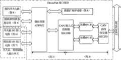
图1为系统总体结构图;Figure 1 is the overall structure diagram of the system;
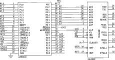
图2为单片机与独立式CAN控制器的接口电路图;Fig. 2 is the interface circuit diagram of single-chip microcomputer and stand-alone CAN controller;
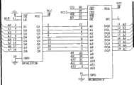
图3为独立式CAN控制器、光耦和总线收发器之间的接口电路图;Fig. 3 is the interface circuit diagram between stand-alone CAN controller, optocoupler and bus transceiver;
图4为拨码开关(设置节点MAC ID及通信波特率)电路图;Fig. 4 is a circuit diagram of a dial switch (setting node MAC ID and communication baud rate);
图5为模块/网络状态指示灯电路图;Figure 5 is a circuit diagram of the module/network status indicator light;
图6为开关量I/O接口电路图;Fig. 6 is a switch quantity I/O interface circuit diagram;
图7为模拟量I/O接口电路图;Fig. 7 is a circuit diagram of an analog I/O interface;
图8为数据扩展存储器连接电路图;Fig. 8 is the connection circuit diagram of data expansion memory;
图9为系统总体程序流程图;Fig. 9 is the overall program flow chart of the system;
图10为中断子程序流程图(包含对于轮询和位选通两种信息的处理过程)。Figure 10 is a flow chart of the interrupt subroutine (including the processing of both polling and bit strobe information).
【具体实施方式】:【Detailed ways】:
实施例1:Example 1:
如图1所示,本实用新型提供的基于多种数据触发方式的DeviceNet现场总线I/O通信装置,包括:As shown in Figure 1, the DeviceNet field bus I/O communication device based on multiple data trigger modes provided by the utility model includes:
DeviceNet接口部分:实现本节点MAC ID及通信波特率的设置,对来自开关量、模拟量输入输出单元的数据处理,以及对DeviceNet协议报文的处理。DeviceNet interface part: realize the setting of MAC ID and communication baud rate of this node, process data from switching value and analog input and output units, and process DeviceNet protocol messages.
开关量、模拟量输入输出单元:包括开关量I/O接口电路(具体连接电路参见图6)和模拟量I/O接口电路(具体连接电路参见图7),用来与外围设备进行I/O通信,可实现8路开关量输入、8路开关量输出、8路模拟量输入和8路模拟量输出的数据采集与输出功能。Digital, analog input and output unit: including digital I/O interface circuit (see Figure 6 for specific connection circuit) and analog I/O interface circuit (see Figure 7 for specific connection circuit), used for I/O with peripheral equipment O communication, which can realize the data acquisition and output functions of 8-way digital input, 8-way digital output, 8-way analog input and 8-way analog output.
其中的DeviceNet接口部分包括:The DeviceNet interface part includes:
微处理器:用于向开关量和模拟量接口电路采集和下发现场数据,接收拨码开关电路所提供的数据,并控制模块/网络状态指示灯的状态;初始化通信对象并有效处理报文信息,解析所接收的总线报文并对将要发送的报文打包,以符合DeviceNet协议规范;Microprocessor: used to collect and send field data to the digital and analog interface circuits, receive the data provided by the DIP switch circuit, and control the status of the module/network status indicator; initialize the communication object and effectively process the message Information, analyze the received bus message and package the message to be sent to comply with the DeviceNet protocol specification;
拨码开关电路:与微处理器双向连接,用于设置通信装置的通信波特率及总线节点号;具体连接电路参见图4。DIP switch circuit: two-way connection with the microprocessor, used to set the communication baud rate and bus node number of the communication device; see Figure 4 for the specific connection circuit.
模块/网络状态指示灯:与微处理器双向连接,用于实时反映通信装置的工作状态及通信状态;具体连接电路参见图5。Module/network status indicator light: bidirectionally connected with the microprocessor, used to reflect the working status and communication status of the communication device in real time; see Figure 5 for the specific connection circuit.
独立式CAN控制器:与微处理器双向连接,用于接收总线报文并向总线发送符合CAN协议的报文;按照CAN规范对总线数据进行判断与过滤,提高本装置的通信效率;具体连接电路参见图2。Independent CAN controller: two-way connection with the microprocessor, used to receive bus messages and send messages conforming to the CAN protocol to the bus; judge and filter the bus data according to the CAN specification, and improve the communication efficiency of the device; the specific connection See Figure 2 for the circuit.
CAN总线收发器:通过光耦与独立式CAN控制器双向连接,用于实现通信装置与总线电平之间的转换;具体连接电路参见图3。CAN bus transceiver: It is bidirectionally connected with an independent CAN controller through an optocoupler, and is used to realize the conversion between the communication device and the bus level; see Figure 3 for the specific connection circuit.
数据扩展存储器:与微处理器双向连接,用于存储大量的通信过程数据及I/O数据。具体连接电路参见图8。Data expansion memory: two-way connection with the microprocessor, used to store a large amount of communication process data and I/O data. Refer to Figure 8 for the specific connection circuit.
其工作过程:Its working process:
如图9所示,首先应用单片机(微处理器)进行状态与模块LED测试,并读取外围拨码开关量,进行本节点的MAC ID和通信波特率的设置,以完成单片机的初始化。随后初始DeviceNet对象、初始化连接对象及CAN控制器,从而完成设备初始化过程。然后进入重复MAC ID检测流程,向DeviceNet总线上发送重复MAC ID检测报文,检测总线上有无相同的MAC ID。检测通过后本节点就连上了DeviceNet总线。As shown in Figure 9, first use the single-chip microcomputer (microprocessor) to test the status and module LED, and read the peripheral DIP switch value, and set the MAC ID and communication baud rate of this node to complete the initialization of the single-chip microcomputer. Then initialize the DeviceNet object, initialize the connection object and the CAN controller, so as to complete the device initialization process. Then enter the duplicate MAC ID detection process, send duplicate MAC ID detection messages to the DeviceNet bus, and check whether there is the same MAC ID on the bus. After passing the test, the node is connected to the DeviceNet bus.
在此之后,本节点进入中断程序(如图10所示),实时检测总线上的数据类型。由于连接到DeviceNet总线后,需要与本节点进行通信的主节点就会发送建立连接邀请,即未连接显示请求报文,因此本节点在接到该报文后会按照要求判断所要建立的连接类型,并根据不同类型配置内部连接及各参数的初始状态,并发送未连接响应信息,以确认所建立的连接。After that, the node enters the interrupt program (as shown in Figure 10) to detect the data type on the bus in real time. After connecting to the DeviceNet bus, the master node that needs to communicate with this node will send an invitation to establish a connection, that is, a display request message if it is not connected, so this node will judge the connection type to be established according to the requirements after receiving the message , and configure the internal connection and the initial state of each parameter according to different types, and send an unconnected response message to confirm the established connection.
连接建立后,本节点继续接收总线报文,并根据报文类型作出处理。当主节点发送的信息为显示报文信息时,本节点立即消费该报文,并根据报文信息寻址本节点的对应类及实例,明确所要完成的类服务事件或实例服务事件,完成相关操作,并生成显示响应报文;当主节点发送的信息为轮询报文时,本节点首先消费该报文,通过解析程序判断其格式的正确性,并提取输出数据,向现场设备下发,然后对采集到的现场数据根据DeviceNet协议格式进行封装,以轮询响应报文予以回应;当主节点发送的信息为位选通命令信息时,本节点的内部程序会转入位选通判断子程序,对信息加以分析判断,此过程需要建立本节点地址位掩码、寻址命令信息中与本节点地址相关的字节并提取选通位,若确为选通本节点的信息,则会执行相关动作,并生成位选通响应信息,以为主节点提供现场数据。After the connection is established, the node continues to receive bus messages and process them according to the message type. When the information sent by the master node is to display the message information, the node immediately consumes the message, and addresses the corresponding class and instance of the node according to the message information, specifies the class service event or instance service event to be completed, and completes the relevant operation , and generate a display response message; when the information sent by the master node is a polling message, the node first consumes the message, judges the correctness of its format through the analysis program, extracts the output data, and sends it to the field device, and then Encapsulate the collected on-site data according to the DeviceNet protocol format, and respond with a polling response message; when the information sent by the master node is bit strobe command information, the internal program of this node will be transferred to the bit strobe judgment subroutine, To analyze and judge the information, this process needs to establish the bit mask of the address of the node, the byte related to the address of the node in the addressing command information and extract the strobe bit, if it is the information of the strobe node, it will execute the relevant action, and generate a bit strobe response message to provide field data to the master node.
Claims (3)
Priority Applications (1)
| Application Number | Priority Date | Filing Date | Title |
|---|---|---|---|
| CNU2008200748991UCN201230327Y (en) | 2008-05-30 | 2008-05-30 | DeviceNet field bus I/O communication apparatus based on multiple data triggering modes |
Applications Claiming Priority (1)
| Application Number | Priority Date | Filing Date | Title |
|---|---|---|---|
| CNU2008200748991UCN201230327Y (en) | 2008-05-30 | 2008-05-30 | DeviceNet field bus I/O communication apparatus based on multiple data triggering modes |
Publications (1)
| Publication Number | Publication Date |
|---|---|
| CN201230327Ytrue CN201230327Y (en) | 2009-04-29 |
Family
ID=40635266
Family Applications (1)
| Application Number | Title | Priority Date | Filing Date |
|---|---|---|---|
| CNU2008200748991UExpired - Fee RelatedCN201230327Y (en) | 2008-05-30 | 2008-05-30 | DeviceNet field bus I/O communication apparatus based on multiple data triggering modes |
Country Status (1)
| Country | Link |
|---|---|
| CN (1) | CN201230327Y (en) |
Cited By (5)
| Publication number | Priority date | Publication date | Assignee | Title |
|---|---|---|---|---|
| CN102955437A (en)* | 2011-08-17 | 2013-03-06 | 秦皇岛天业通联重工股份有限公司 | Bus expansion module of engineering machinery vehicle and bus data processing method |
| CN108645454A (en)* | 2018-07-25 | 2018-10-12 | 重庆朗威仪器仪表股份有限公司 | A kind of full isolation remote I/O data acquisition system |
| CN110601923A (en)* | 2019-09-19 | 2019-12-20 | 宁波三星医疗电气股份有限公司 | Working mode configuration method, communication module and power terminal |
| CN111208773A (en)* | 2020-03-16 | 2020-05-29 | 成都兴蓉沱源自来水有限责任公司 | Universal frequency converter control module based on DeviceNet field bus |
| CN111475439A (en)* | 2020-04-08 | 2020-07-31 | 北京龙鼎源科技股份有限公司 | Communication control method and device based on asynchronous transmission protocol and electronic equipment |
- 2008
- 2008-05-30CNCNU2008200748991Upatent/CN201230327Y/ennot_activeExpired - Fee Related
Cited By (6)
| Publication number | Priority date | Publication date | Assignee | Title |
|---|---|---|---|---|
| CN102955437A (en)* | 2011-08-17 | 2013-03-06 | 秦皇岛天业通联重工股份有限公司 | Bus expansion module of engineering machinery vehicle and bus data processing method |
| CN108645454A (en)* | 2018-07-25 | 2018-10-12 | 重庆朗威仪器仪表股份有限公司 | A kind of full isolation remote I/O data acquisition system |
| CN110601923A (en)* | 2019-09-19 | 2019-12-20 | 宁波三星医疗电气股份有限公司 | Working mode configuration method, communication module and power terminal |
| CN110601923B (en)* | 2019-09-19 | 2021-06-01 | 宁波三星医疗电气股份有限公司 | Working mode configuration method, communication module and power terminal |
| CN111208773A (en)* | 2020-03-16 | 2020-05-29 | 成都兴蓉沱源自来水有限责任公司 | Universal frequency converter control module based on DeviceNet field bus |
| CN111475439A (en)* | 2020-04-08 | 2020-07-31 | 北京龙鼎源科技股份有限公司 | Communication control method and device based on asynchronous transmission protocol and electronic equipment |
Similar Documents
| Publication | Publication Date | Title |
|---|---|---|
| CN101685301B (en) | Embedded type state monitoring information adaptor capable of operating under complex working conditions of numerically-controlled machine tool and method thereof | |
| CN201230327Y (en) | DeviceNet field bus I/O communication apparatus based on multiple data triggering modes | |
| CN101710883A (en) | Multi-protocol data acquisition gateway for intelligent building and data acquisition method thereof | |
| CN105335316A (en) | Motor assembling line serial port server based on cloud computation | |
| CN113028603B (en) | Equipment monitoring system applied to central air-conditioning system | |
| CN103944982A (en) | Data collecting and controlling device and method for heterogeneous sensor network | |
| CN106777755B (en) | Verification device and system for spacer layer locking logic | |
| CN201550135U (en) | Radio embedded type gateway for building energy consumption measurement and environmental monitoring | |
| CN103067201B (en) | A kind of multi-protocol communication manager | |
| CN101464686B (en) | An Embedded Substation Based on CPCI Bus | |
| CN102710622A (en) | Protocol conversion device based on DeviceNet-Modbus | |
| CN201504290U (en) | Substation intelligent video control device | |
| CN204406186U (en) | A kind of fieldbus controller | |
| CN203219328U (en) | A multi-channel communication protocol converter | |
| CN101639694A (en) | Control system based on EPA standard and management method thereof | |
| CN204244262U (en) | Conformance Test Setup for IEC 61850 Profiles Based on the NI CRIO Platform | |
| CN103944738B (en) | A kind of interchanger for supporting Function Extension | |
| CN100423518C (en) | Embedded Home Gateway Based on Consumer Bus | |
| CN116074397B (en) | Data sharing system | |
| CN117978882A (en) | Protocol conversion method capable of customizing extension protocol and protocol adapter plate | |
| CN207817133U (en) | Distributed power net fault wave recording device | |
| CN108391245A (en) | Plug and play type wireless sensor network node | |
| CN104348920A (en) | DCS (distributed control system) self-networking monitoring system based on OPC (OLE (object linking and embedding) for process control) standards | |
| CN102722975A (en) | Method and system for reading data of electricity meter based on PROFIBUS | |
| CN1084899C (en) | Development emulate system of multiway transmission data bus |
Legal Events
| Date | Code | Title | Description |
|---|---|---|---|
| C14 | Grant of patent or utility model | ||
| GR01 | Patent grant | ||
| C17 | Cessation of patent right | ||
| CF01 | Termination of patent right due to non-payment of annual fee | Granted publication date:20090429 Termination date:20130530 |