CN201230069Y - Electric connector - Google Patents
Electric connectorDownload PDFInfo
- Publication number
- CN201230069Y CN201230069YCNU2008200358897UCN200820035889UCN201230069YCN 201230069 YCN201230069 YCN 201230069YCN U2008200358897 UCNU2008200358897 UCN U2008200358897UCN 200820035889 UCN200820035889 UCN 200820035889UCN 201230069 YCN201230069 YCN 201230069Y
- Authority
- CN
- China
- Prior art keywords
- electrical connector
- base
- printed circuit
- circuit board
- receiving groove
- Prior art date
- Legal status (The legal status is an assumption and is not a legal conclusion. Google has not performed a legal analysis and makes no representation as to the accuracy of the status listed.)
- Expired - Lifetime
Links
Images


Classifications
- H—ELECTRICITY
- H01—ELECTRIC ELEMENTS
- H01R—ELECTRICALLY-CONDUCTIVE CONNECTIONS; STRUCTURAL ASSOCIATIONS OF A PLURALITY OF MUTUALLY-INSULATED ELECTRICAL CONNECTING ELEMENTS; COUPLING DEVICES; CURRENT COLLECTORS
- H01R13/00—Details of coupling devices of the kinds covered by groups H01R12/70 or H01R24/00 - H01R33/00
- H01R13/66—Structural association with built-in electrical component
- H01R13/665—Structural association with built-in electrical component with built-in electronic circuit
- H01R13/6658—Structural association with built-in electrical component with built-in electronic circuit on printed circuit board
- H—ELECTRICITY
- H01—ELECTRIC ELEMENTS
- H01R—ELECTRICALLY-CONDUCTIVE CONNECTIONS; STRUCTURAL ASSOCIATIONS OF A PLURALITY OF MUTUALLY-INSULATED ELECTRICAL CONNECTING ELEMENTS; COUPLING DEVICES; CURRENT COLLECTORS
- H01R13/00—Details of coupling devices of the kinds covered by groups H01R12/70 or H01R24/00 - H01R33/00
- H01R13/646—Details of coupling devices of the kinds covered by groups H01R12/70 or H01R24/00 - H01R33/00 specially adapted for high-frequency, e.g. structures providing an impedance match or phase match
- H01R13/6461—Means for preventing cross-talk
- H—ELECTRICITY
- H01—ELECTRIC ELEMENTS
- H01R—ELECTRICALLY-CONDUCTIVE CONNECTIONS; STRUCTURAL ASSOCIATIONS OF A PLURALITY OF MUTUALLY-INSULATED ELECTRICAL CONNECTING ELEMENTS; COUPLING DEVICES; CURRENT COLLECTORS
- H01R13/00—Details of coupling devices of the kinds covered by groups H01R12/70 or H01R24/00 - H01R33/00
- H01R13/66—Structural association with built-in electrical component
- H01R13/719—Structural association with built-in electrical component specially adapted for high frequency, e.g. with filters
- H01R13/7195—Structural association with built-in electrical component specially adapted for high frequency, e.g. with filters with planar filters with openings for contacts
- H—ELECTRICITY
- H01—ELECTRIC ELEMENTS
- H01R—ELECTRICALLY-CONDUCTIVE CONNECTIONS; STRUCTURAL ASSOCIATIONS OF A PLURALITY OF MUTUALLY-INSULATED ELECTRICAL CONNECTING ELEMENTS; COUPLING DEVICES; CURRENT COLLECTORS
- H01R13/00—Details of coupling devices of the kinds covered by groups H01R12/70 or H01R24/00 - H01R33/00
- H01R13/648—Protective earth or shield arrangements on coupling devices, e.g. anti-static shielding
- H01R13/658—High frequency shielding arrangements, e.g. against EMI [Electro-Magnetic Interference] or EMP [Electro-Magnetic Pulse]
- H01R13/6591—Specific features or arrangements of connection of shield to conductive members
- H01R13/6592—Specific features or arrangements of connection of shield to conductive members the conductive member being a shielded cable
- H01R13/6593—Specific features or arrangements of connection of shield to conductive members the conductive member being a shielded cable the shield being composed of different pieces
Landscapes
- Engineering & Computer Science (AREA)
- Microelectronics & Electronic Packaging (AREA)
- Details Of Connecting Devices For Male And Female Coupling (AREA)
- Coupling Device And Connection With Printed Circuit (AREA)
Abstract
Description
Translated fromChinese【技术领域】【Technical field】
本实用新型有关一种电连接器,尤其是指一种其内含有印刷电路板的电连接器。The utility model relates to an electric connector, in particular to an electric connector containing a printed circuit board.
【背景技术】【Background technique】
电连接器内通常具有若干导电端子,其可与印刷电路板的焊接端子及对接连接器的导电端子电性连接进而实现电信号的传输。随着技术的进步及消费者对产品要求的提高,自通用串行总线(USB)连接器问世以来,其传输速度及性能上得到了极大的改进,在电气性能提高的同时,电子设备外接连接器产品小巧化也成为了一种必然的趋势。The electrical connector usually has a plurality of conductive terminals, which can be electrically connected with the soldering terminals of the printed circuit board and the conductive terminals of the mating connector to realize the transmission of electrical signals. With the advancement of technology and the improvement of consumer requirements for products, since the advent of the Universal Serial Bus (USB) connector, its transmission speed and performance have been greatly improved. While the electrical performance is improved, the external connection of electronic equipment The miniaturization of connector products has also become an inevitable trend.
中华人民共和国实用新型专利公告第2582214号揭示了一种线缆连接器,其插入部件包括设有舌板的基座,收容于基座内的端子及与端子焊接且位于基座后方的印刷电路板,所述印刷电路板上可安装其他控制芯片或元器件,这样设计虽不影响其使用,但印刷电路板与端子仅仅依靠焊点连接,没有相互之间的固持,经过多次插拔过程极易造成焊点松动,影响电气性能,再者,印刷电路板位于基座后方,增大了电连接器的整体长度,不利于电连接器的小型化发展趋势。The Utility Model Patent Announcement No. 2582214 of the People’s Republic of China discloses a cable connector, the insertion part of which includes a base with a tongue plate, a terminal accommodated in the base and a printed circuit welded with the terminal and located behind the base Board, the printed circuit board can be installed with other control chips or components, although this design does not affect its use, but the printed circuit board and the terminal are only connected by solder joints, there is no mutual fixation, after many times of plugging and unplugging process It is very easy to cause loose solder joints and affect the electrical performance. Furthermore, the printed circuit board is located behind the base, which increases the overall length of the electrical connector, which is not conducive to the development trend of miniaturization of the electrical connector.
因此,确有必要对现有电连接器进行改进来克服所述的缺陷。Therefore, it is indeed necessary to improve the existing electrical connectors to overcome the above-mentioned defects.
【发明内容】【Content of invention】
本实用新型提供一种电连接器,其内设有可有效抵持导电端子的印刷电路板,从而确保电性传输的可靠性,且可减小电连接器的整体长度。The utility model provides an electric connector, which is provided with a printed circuit board which can effectively support the conductive terminal, so as to ensure the reliability of electric transmission and reduce the overall length of the electric connector.
为实现上述目的,本实用新型电连接器包括绝缘壳体、部分收容于其内的金属壳体及收容于金属壳体内的连接部件,所述连接部件包括有基座、收容于基座内的导电端子及可与导电端子连接的印刷电路板,其中,所述基座一端设有一收容槽,所述印刷电路板收容于该收容槽内且与收容于基座内的导电端子相抵接。In order to achieve the above object, the electrical connector of the utility model includes an insulating shell, a metal shell partially accommodated therein, and a connecting part accommodated in the metal shell. The conductive terminal and the printed circuit board that can be connected with the conductive terminal, wherein, one end of the base is provided with a receiving groove, and the printed circuit board is accommodated in the receiving groove and abuts against the conductive terminal accommodated in the base.
与现有技术相比,本实用新型电连接器通过将印刷电路板收容入基座内并与导电端子相抵持,不仅提高了电性连接的可靠性,且大大节约了印刷电路板的占用空间,减小了电连接器的整体尺寸。Compared with the prior art, the electrical connector of the utility model not only improves the reliability of the electrical connection, but also greatly saves the occupied space of the printed circuit board by accommodating the printed circuit board in the base and abutting against the conductive terminals. , reducing the overall size of the electrical connector.
【附图说明】【Description of drawings】
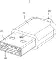
图1为本实用新型电连接器的立体图。FIG. 1 is a perspective view of the electrical connector of the present invention.
图2为本实用新型电连接器的立体分解图。Fig. 2 is a three-dimensional exploded view of the electrical connector of the present invention.
图3为本实用新型电连接器的连接部件立体图。Fig. 3 is a perspective view of the connecting parts of the electrical connector of the present invention.
图4为本实用新型电连接器的连接部件另一角度的立体图。FIG. 4 is a perspective view from another angle of the connecting part of the electrical connector of the present invention.
图5为图3所示电连接器连接部件的立体分解图。FIG. 5 is an exploded perspective view of the connecting part of the electrical connector shown in FIG. 3 .
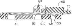
图6为图3所示连接部件沿A-A线的剖视图。Fig. 6 is a cross-sectional view of the connection part shown in Fig. 3 along line A-A.
【具体实施方式】【Detailed ways】
请参阅图1及图2所示,本实用新型电连接器1在本实施例中是一USB电连接器,其包括绝缘壳体10,部分收容于绝缘壳体10内的金属壳体30,与金属壳体30相扣持的金属盖体40,安装于金属壳体30内的连接部件80及绝缘材料注塑形成于电连接器1内后端的注塑件20。所述绝缘壳体10包括一收容部11,其向后贯通有一收容外接线缆的通孔(未图示)。Please refer to FIG. 1 and FIG. 2, the utility model
请参阅图3至图6所示,所述连接部件80包括绝缘基座60,收容于其内的导电端子50及压接于导电端子50尾部且收容于基座60内的印刷电路板(PCB)70。所述基座60包括有安装部62,舌板61及连接安装部62与舌板61的台阶部63,所述安装部62凹设形成一顶部开放的收容槽66,位于收容槽66两侧的侧壁67内侧开设有与收容槽66相互连通的滑槽65,收容槽66底部设有若干贯穿台阶部63至舌板61的端子通道610,各端子通道610向下开设有固定孔611。所述舌板61是自台阶部63下部部分向前延伸形成的,所述端子通道610位于舌板61及安装部62处的部分可见,位于台阶部63内的部分不可见(如图6所示)。所述基座60的台阶部63中部还凹设有一端开放的凹槽64(如图2所示)。Please refer to FIGS. 3 to 6, the connecting
所述导电端子50包括一向上突起的接触部51,自接触部51向后延伸形成有固定部(未标号),固定部中间部分向下凹陷形成一卡止部53,自固定部向后部分延伸形成焊接端52。组装时该导电端子50自基座60的安装部62方向插入端子通道610中,其贯穿台阶部63直至所述卡止部53固持于端子通道610内的固定孔611内,此时,导电端子50的接触部51突出于舌板61表面,焊接端52延伸出基座60安装部62外。The
所述印刷电路板70大致呈矩形状,其具有顶壁71、底壁72及两侧部74,所述顶壁71、底壁72上都设有若干焊接点(未标号),且顶壁71一端设有一个元件安装区域73,其上可以焊接若干个电子元器件(如控制芯片等),该印刷电路板70的侧部74沿滑槽65滑动使印刷电路板70部分收容入基座60的收容槽66内,并使印刷电路板70底壁72的焊接点紧紧抵持住收容于端子通道610内的导电端子50的焊接端52,这样设计,不仅减小了印刷电路板70的占用空间,同时,使印刷电路板70与导电端子50紧紧抵持,焊接后不会因外力作用而使焊点松动,达到提高电气传输性能的目的。The printed
请参阅图2所示,所述金属壳体30包括上下两个主体部31及用于连接两主体部31的两个侧壁32,并由此围设成一个用于收容连接部件80的收容腔34,金属壳体30的侧壁32后端形成缺口321及延伸片322,顶部的主体部31向下凹陷形成一与所述凹槽64抵接的抵接部311,同时顶部的主体部31后端向后延伸突出有一结合部33。配合金属壳体30的金属盖体40包括一平台部41,自平台部41向上弯折有若干片状体421、422,其分别与所述缺口321及延伸片322对应扣合。自平台部41向后部分延伸并卷曲形成有一对应所述结合部33的线缆紧固孔43。Please refer to FIG. 2 , the
请参阅图1至图6所示,在安装制造过程中,第一步,组装连接部件80,先将导电端子50插入端子通道610内固持,再将印刷电路板70顺着基座60的滑槽65推滑入基座60的收容槽66内,此时印刷电路板70底壁72的焊接点紧紧抵持已装入基座60内的导电端子50的焊接端52,同时将导电端子50的焊接端52与印刷电路板70的焊接点焊接。一外接线缆(未图示)焊接于印刷电路板70的焊接点上。第二步,连接部件80与金属壳体30、配合壳体40及绝缘壳体10的安装,将电性焊接于印刷电路板70上的线缆穿过配合壳体40的线缆紧固孔43,将安装好后的连接部件80对应装入金属壳体30内,直至所述台阶部63的凹槽64抵住金属壳体30的抵接部311,再将金属盖体40自下向上安装于金属壳体30上,同时,将线缆紧固孔43与金属壳体结合部33弯曲拧紧。将线缆穿过绝缘壳体10的收容部11。最后,将安装了连接部件80及金属盖体40后的金属壳体30装入绝缘壳体10的收容部11内。第三步,注塑,安装完成后电连接器1通过辅助工具将绝缘材料注入电连接器1内的多余的空间中(诸如金属壳体30与绝缘壳体10之间及金属壳体30安装连接部件80后后端多余的空间),并由此形成一个不规则的注塑件20,其在具体实施时不一定为图示形状,图示仅代表此为一注塑形成的物体,其内空形成一线缆孔24,其后端形成一帽端22且穿过绝缘壳体10露出于外部以保护线缆。Please refer to FIGS. 1 to 6. In the installation and manufacturing process, the first step is to assemble the
相较于现有技术,本实用新型电连接器通过基座60设有收容槽66及滑槽65,将印刷电路板70沿滑槽65推入并收容于收容槽66内,同时,印刷电路板70紧紧抵持住已装入基座60内的导电端子50的焊接端52,这样设计,不仅使印刷电路板70与导电端子50焊接后不会因外力作用而使焊点松动,从而达到提高电气传输性能的目的,而且印刷电路板70收容入基座60内,从而减小了印刷电路板70的占用空间,进而减小了电连接器1的整体长度。Compared with the prior art, the electrical connector of the utility model is provided with a receiving groove 66 and a chute 65 through the
Claims (8)
Translated fromChinesePriority Applications (2)
| Application Number | Priority Date | Filing Date | Title |
|---|---|---|---|
| CNU2008200358897UCN201230069Y (en) | 2008-04-30 | 2008-04-30 | Electric connector |
| US12/432,768US7798853B2 (en) | 2008-04-30 | 2009-04-30 | USB connector having noise-suppressing device |
Applications Claiming Priority (1)
| Application Number | Priority Date | Filing Date | Title |
|---|---|---|---|
| CNU2008200358897UCN201230069Y (en) | 2008-04-30 | 2008-04-30 | Electric connector |
Publications (1)
| Publication Number | Publication Date |
|---|---|
| CN201230069Ytrue CN201230069Y (en) | 2009-04-29 |
Family
ID=40635012
Family Applications (1)
| Application Number | Title | Priority Date | Filing Date |
|---|---|---|---|
| CNU2008200358897UExpired - LifetimeCN201230069Y (en) | 2008-04-30 | 2008-04-30 | Electric connector |
Country Status (2)
| Country | Link |
|---|---|
| US (1) | US7798853B2 (en) |
| CN (1) | CN201230069Y (en) |
Cited By (7)
| Publication number | Priority date | Publication date | Assignee | Title |
|---|---|---|---|---|
| CN102157821A (en)* | 2010-01-04 | 2011-08-17 | 泰科电子荷兰公司 | Electrical component comprising a hotmelt element |
| CN102157822A (en)* | 2010-01-04 | 2011-08-17 | 泰科电子荷兰公司 | Electrical connecting component comprosing a hotmelt element, method and tool for manufacturing such an electrical component |
| CN103117464A (en)* | 2013-02-06 | 2013-05-22 | 蹇在义 | A kind of USB plug connector and processing method |
| CN106654735A (en)* | 2015-11-03 | 2017-05-10 | 聚鼎科技股份有限公司 | Connector with a locking member |
| CN110137721A (en)* | 2018-02-09 | 2019-08-16 | 巧连科技股份有限公司 | Electric connector structure |
| CN110582898A (en)* | 2017-05-10 | 2019-12-17 | 第一精工株式会社 | Connector |
| CN116632581A (en)* | 2023-07-06 | 2023-08-22 | 东莞市维克电子科技有限公司 | Shielding shells and connectors for integrated connectors |
Families Citing this family (28)
| Publication number | Priority date | Publication date | Assignee | Title |
|---|---|---|---|---|
| CN201498633U (en)* | 2009-07-02 | 2010-06-02 | 富士康(昆山)电脑接插件有限公司 | Electrical connector |
| US8506327B2 (en)* | 2009-09-30 | 2013-08-13 | Eric Jol | Portable electronic devices with sealed connectors |
| US8246383B2 (en) | 2010-03-19 | 2012-08-21 | Apple Inc. | Sealed connectors for portable electronic devices |
| CN102214858A (en)* | 2010-04-07 | 2011-10-12 | 富士康(昆山)电脑接插件有限公司 | Cable connector component and manufacturing method thereof |
| TWM393846U (en)* | 2010-05-25 | 2010-12-01 | Molex Taiwan Ltd | Plug connector |
| US8113865B1 (en)* | 2010-08-27 | 2012-02-14 | Cheng Uei Precision Industry Co., Ltd. | Plug connector |
| CN201829743U (en)* | 2010-09-23 | 2011-05-11 | 富士康(昆山)电脑接插件有限公司 | Cable connector component |
| TW201216570A (en)* | 2010-10-13 | 2012-04-16 | Asustek Comp Inc | Connector |
| CN102456977B (en)* | 2010-10-23 | 2014-09-24 | 富士康(昆山)电脑接插件有限公司 | Cable Connector Assembly |
| CN102496804A (en)* | 2011-11-22 | 2012-06-13 | 华为终端有限公司 | USB (universal serial bus) connector and electronic equipment |
| US20130164990A1 (en)* | 2011-12-21 | 2013-06-27 | Chou Hsien Tsai | Electrical connector |
| US20130178110A1 (en)* | 2012-01-07 | 2013-07-11 | Cheng Uei Precision Industry Co., Ltd. | Plug connector |
| TWI479757B (en)* | 2012-05-30 | 2015-04-01 | Singatron Electronic China Co | High definition multimedia connector and its manufacturing method |
| US20140206209A1 (en) | 2013-01-24 | 2014-07-24 | Apple Inc. | Reversible usb connector |
| US9048584B2 (en)* | 2013-01-31 | 2015-06-02 | Tyco Electronics Corporation | Electrical connector system having an insulator holding terminals |
| TWM458687U (en)* | 2013-02-07 | 2013-08-01 | Tuton Technology Co Ltd | USB connector and USB transmission line with signal processing IC |
| CN106415944A (en) | 2014-04-23 | 2017-02-15 | 泰科电子公司 | Electrical connector with shield cap and shielded terminals |
| CN105337082B (en)* | 2014-06-09 | 2018-05-04 | 富士康(昆山)电脑接插件有限公司 | Connector assembly and its manufacture method |
| JP5813846B1 (en)* | 2014-10-27 | 2015-11-17 | 日本航空電子工業株式会社 | Waterproof connector |
| US9823286B2 (en) | 2015-04-27 | 2017-11-21 | Motorola Mobility Llc | Moisture detection system for external electrical connector and methods therefor |
| CN206364219U (en)* | 2016-12-16 | 2017-07-28 | 富鼎精密工业(郑州)有限公司 | Connector assembly |
| KR102399821B1 (en) | 2017-03-28 | 2022-05-19 | 삼성전자주식회사 | Pcb including connector and grounds with different potentials and electronic device having the same |
| KR102457138B1 (en) | 2018-05-17 | 2022-10-21 | 삼성전자주식회사 | Electronic device with connector |
| EP3648264A1 (en)* | 2018-10-31 | 2020-05-06 | Koninklijke Philips N.V. | Electrical connector with usb series a contact pad pitch |
| USD885391S1 (en) | 2018-11-04 | 2020-05-26 | Kien Hoe Daniel Chin | USB adapter apparatus |
| USD891433S1 (en) | 2018-11-04 | 2020-07-28 | Kien Hoe Daniel Chin | USB adapter apparatus |
| USD969081S1 (en)* | 2020-05-29 | 2022-11-08 | Sony Interactive Entertainment Inc. | Connector |
| USD979509S1 (en)* | 2020-05-29 | 2023-02-28 | Sony Interactive Entertainment Inc. | Connector |
Family Cites Families (10)
| Publication number | Priority date | Publication date | Assignee | Title |
|---|---|---|---|---|
| US5069641A (en) | 1990-02-03 | 1991-12-03 | Murata Manufacturing Co., Ltd. | Modular jack |
| US5797771A (en)* | 1996-08-16 | 1998-08-25 | U.S. Robotics Mobile Communication Corp. | Cable connector |
| JP2000068007A (en)* | 1998-08-20 | 2000-03-03 | Fujitsu Takamisawa Component Ltd | Connector for balanced transmission with cable |
| US6582252B1 (en)* | 2002-02-11 | 2003-06-24 | Hon Hai Precision Ind. Co., Ltd. | Termination connector assembly with tight angle for shielded cable |
| US6776658B2 (en) | 2002-08-06 | 2004-08-17 | Hon Hai Precision Ind. Co., Ltd. | Cable end connector |
| US6869308B2 (en)* | 2002-12-11 | 2005-03-22 | Hon Hai Precision Ind. Co., Ltd. | Cable connector having cross-talk suppressing feature and method for making the connector |
| JP4373810B2 (en)* | 2004-02-13 | 2009-11-25 | 富士通コンポーネント株式会社 | Cable connector for balanced transmission |
| US7407390B1 (en)* | 2005-05-16 | 2008-08-05 | Super Talent Electronics, Inc. | USB device with plastic housing having inserted plug support |
| US7410366B2 (en)* | 2006-08-25 | 2008-08-12 | Hon Hai Precision Ind. Co., Ltd. | Electrical connector assembly with reduced crosstalk and electromaganectic interference |
| US7575481B1 (en)* | 2008-12-24 | 2009-08-18 | Chen-Ya Liu | USB plug with a built-in-card-reading slot |
- 2008
- 2008-04-30CNCNU2008200358897Upatent/CN201230069Y/ennot_activeExpired - Lifetime
- 2009
- 2009-04-30USUS12/432,768patent/US7798853B2/ennot_activeExpired - Fee Related
Cited By (8)
| Publication number | Priority date | Publication date | Assignee | Title |
|---|---|---|---|---|
| CN102157821A (en)* | 2010-01-04 | 2011-08-17 | 泰科电子荷兰公司 | Electrical component comprising a hotmelt element |
| CN102157822A (en)* | 2010-01-04 | 2011-08-17 | 泰科电子荷兰公司 | Electrical connecting component comprosing a hotmelt element, method and tool for manufacturing such an electrical component |
| CN102157822B (en)* | 2010-01-04 | 2015-01-21 | 泰科电子荷兰公司 | Electrical connecting component comprosing a hotmelt element, method and tool for manufacturing such an electrical component |
| CN103117464A (en)* | 2013-02-06 | 2013-05-22 | 蹇在义 | A kind of USB plug connector and processing method |
| CN106654735A (en)* | 2015-11-03 | 2017-05-10 | 聚鼎科技股份有限公司 | Connector with a locking member |
| CN110582898A (en)* | 2017-05-10 | 2019-12-17 | 第一精工株式会社 | Connector |
| CN110137721A (en)* | 2018-02-09 | 2019-08-16 | 巧连科技股份有限公司 | Electric connector structure |
| CN116632581A (en)* | 2023-07-06 | 2023-08-22 | 东莞市维克电子科技有限公司 | Shielding shells and connectors for integrated connectors |
Also Published As
| Publication number | Publication date |
|---|---|
| US20090275235A1 (en) | 2009-11-05 |
| US7798853B2 (en) | 2010-09-21 |
Similar Documents
| Publication | Publication Date | Title |
|---|---|---|
| CN201230069Y (en) | Electric connector | |
| CN201638995U (en) | Connector | |
| US9437982B2 (en) | Cable connector assembly | |
| CN201178190Y (en) | cable connector | |
| CN201113072Y (en) | Electrical Connector Assembly | |
| JP4493710B2 (en) | Electrical connector | |
| JP4618745B1 (en) | Electrical connector | |
| CN2932722Y (en) | Electrical connectors and their components | |
| JP2013508897A (en) | Electrical connector | |
| CN101473496B (en) | Connector for coaxial cable | |
| CN2932744Y (en) | electrical connector | |
| CN101136524A (en) | Electrical connector and manufacturing method thereof | |
| JP2003229214A (en) | Electrical connector | |
| CN201230076Y (en) | Electric connector | |
| CN201374444Y (en) | electrical connector | |
| CN201887202U (en) | Electric connector component | |
| CN202633671U (en) | Flexible cable assembly | |
| CN203225388U (en) | Cable connector | |
| JP5181944B2 (en) | Electrical connector | |
| CN101740926B (en) | Electric connector | |
| CN101527415A (en) | Electronic switching device | |
| CN201797085U (en) | electronic card connector | |
| CN102790312A (en) | Electric connector | |
| CN201112977Y (en) | electrical connector | |
| CN215989344U (en) | Electrical connector |
Legal Events
| Date | Code | Title | Description |
|---|---|---|---|
| C14 | Grant of patent or utility model | ||
| GR01 | Patent grant | ||
| CX01 | Expiry of patent term | Granted publication date:20090429 | |
| CX01 | Expiry of patent term |