CN201171665Y - Stereo electronic endoscope dual-channel video signal acquisition device - Google Patents
Stereo electronic endoscope dual-channel video signal acquisition deviceDownload PDFInfo
- Publication number
- CN201171665Y CN201171665YCNU2008200713808UCN200820071380UCN201171665YCN 201171665 YCN201171665 YCN 201171665YCN U2008200713808 UCNU2008200713808 UCN U2008200713808UCN 200820071380 UCN200820071380 UCN 200820071380UCN 201171665 YCN201171665 YCN 201171665Y
- Authority
- CN
- China
- Prior art keywords
- lens
- video signal
- mirror
- signal acquisition
- light guide
- Prior art date
- Legal status (The legal status is an assumption and is not a legal conclusion. Google has not performed a legal analysis and makes no representation as to the accuracy of the status listed.)
- Expired - Fee Related
Links
- 238000003384imaging methodMethods0.000claimsabstractdescription12
- 230000003287optical effectEffects0.000claimsabstractdescription9
- 239000013307optical fiberSubstances0.000claimsdescription2
- PEDCQBHIVMGVHV-UHFFFAOYSA-NGlycerineChemical compoundOCC(O)COPEDCQBHIVMGVHV-UHFFFAOYSA-N0.000claims2
- 239000006059cover glassSubstances0.000claims1
- 230000005622photoelectricityEffects0.000claims1
- 230000000007visual effectEffects0.000claims1
- 238000005516engineering processMethods0.000abstractdescription7
- 230000000694effectsEffects0.000abstractdescription2
- 238000006243chemical reactionMethods0.000description2
- 238000005260corrosionMethods0.000description2
- 230000007797corrosionEffects0.000description2
- 238000010586diagramMethods0.000description2
- 238000005286illuminationMethods0.000description2
- 238000009434installationMethods0.000description2
- 239000000463materialSubstances0.000description2
- 230000005499meniscusEffects0.000description2
- 238000012634optical imagingMethods0.000description2
- 230000004075alterationEffects0.000description1
- 230000005540biological transmissionEffects0.000description1
- 210000001124body fluidAnatomy0.000description1
- 239000010839body fluidSubstances0.000description1
- 238000011109contaminationMethods0.000description1
- 238000001914filtrationMethods0.000description1
- 239000011521glassSubstances0.000description1
- 238000001746injection mouldingMethods0.000description1
- 238000000034methodMethods0.000description1
- 230000001681protective effectEffects0.000description1
- 239000000243solutionSubstances0.000description1
- 229910001220stainless steelInorganic materials0.000description1
- 239000010935stainless steelSubstances0.000description1
Images


Landscapes
- Endoscopes (AREA)
- Instruments For Viewing The Inside Of Hollow Bodies (AREA)
Abstract
Translated fromChinese
Description
Translated fromChinese技术领域technical field
本实用新型涉及一种立体电子内窥镜系统中的视频信号获得装置,属于医用光学电子仪器技术领域。The utility model relates to a video signal acquisition device in a three-dimensional electronic endoscope system, which belongs to the technical field of medical optical and electronic instruments.
背景技术Background technique
与本实用新型相关的已知技术是一种被称为立体电视内窥镜的方案,其视频信号获得装置外形见图1所示,由镜杆1、握柄2、CCD电缆接口3、导光束接口4组成,其两路光学成像系统以及光电转换部件安装在镜杆1中,光学成像系统通常由物镜系统、转像系统、目镜、投影物镜组成,在导光束的照明下获取光学影像并投影到光电转换部件CCD的光电靶面上转换为视频信号,经CCD电缆传输到立体图像处理器,经体视处理后在显示器上显示出立体图像。Known technology relevant to the utility model is a kind of scheme that is called stereoscopic TV endoscope, and its video signal acquisition device profile is shown in Figure 1, by
实用新型内容Utility model content
已知技术存在的主要问题是,结构复杂,光学组件多,重量大,光能损失大,图像分辨率低。为了解决已知技术存在的问题,同时使所提出技术方案更为具体、实用、照明均匀、安装调整方便,我们设计了本实用新型之立体电子内窥镜双路视频信号获得装置。The main problems of the known technology are complex structure, many optical components, heavy weight, large light energy loss and low image resolution. In order to solve the existing problems of the known technology, and to make the proposed technical solution more specific, practical, uniform in illumination and convenient for installation and adjustment, we have designed a dual-channel video signal acquisition device for a stereoscopic electronic endoscope of the present utility model.
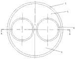
本实用新型是这样实现的,见图1、图2、图3所示,所述的装置由镜杆1、两个视频信号获得部件、导光束5组成,两个视频信号获得部件并列且位于镜杆1前端A内,每个视频信号获得部件由镜管6以及安装其内的物镜7、CCD固态成像单元8、电缆9组成,CCD固态成像单元8的光电靶面10位于物镜7的焦平面上,电缆9接CCD固态成像单元8,两个视频信号获得部件中的物镜7光轴平行,导光束5位于镜杆1内壁与两个镜管6外壁之间的空间内。The utility model is realized in this way, as shown in Fig. 1, Fig. 2 and Fig. 3, the described device is made up of a
本实用新型与已知技术相比,核心部分只有物镜7和CCD固态成像单元8,结构大为简化,重量减轻,光能损失减小。导光束5分布于并列的两个镜管6上下,照明效果改善。图像像质因上述措施得到改善。物镜7和CCD固态成像单元8集中在镜杆1的前端,与已知技术相比完全可以通过加长电缆9完成视频信号的正常输出。Compared with the known technology, the utility model only has the objective lens 7 and the CCD solid-
附图说明Description of drawings
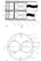
图1是已知技术立体电视内窥镜视频信号获得装置外形示意图。图2是本实用新型之装置端面示意图。图3是本实用新型之装置图1A部分的局部放大及沿图2A-A方向的剖视示意图。图4是本实用新型之装置的具体实施方式端面示意图。图5是本实用新型之装置的具体实施方式图1A部分的局部放大及沿图4A-A方向的剖视示意图,该图兼作摘要附图。Fig. 1 is a schematic diagram of the appearance of a stereoscopic TV endoscope video signal acquisition device in the known technology. Fig. 2 is a schematic view of the end face of the device of the present invention. Fig. 3 is a partially enlarged part of Fig. 1A of the device of the present invention and a schematic cross-sectional view along the direction of Fig. 2A-A. Fig. 4 is a schematic diagram of the end face of a specific embodiment of the device of the present invention. Fig. 5 is a partial enlarged part of Fig. 1A and a schematic cross-sectional view along the direction of Fig. 4A-A of the specific embodiment of the device of the present invention, which is also used as a summary drawing.
具体实施方式Detailed ways
本实用新型的具体实施方式如下,见图1、图4、图5所示,所述的装置由镜杆1、两个视频信号获得部件、导光束5组成。镜杆1采用不锈钢材料制作,外径为8~12毫米。两个视频信号获得部件并列且位于镜杆1前端A内,每个视频信号获得部件由镜管6以及安装其内的物镜7、CCD固态成像单元8、电缆9组成,CCD固态成像单元8的光电靶面10位于物镜7的焦平面上,电缆9接CCD固态成像单元8,两个视频信号获得部件中的物镜7光轴平行。物镜7采用三片式结构,即一片负透镜和由两片透镜组合而成的正透镜。负透镜采用平凹透镜11,平面为进光端。正透镜为一片弯月厚透镜12和一片双凸透镜13的组合。在平凹透镜11和弯月厚透镜12之间安装孔径光阑14。两个物镜7的光轴间距为5~10毫米,根据立体电子内窥镜的体视要求确定具体值。所述的三片式结构物镜具有结构紧凑、像差小的特点。为了避免所窥视的生物体体液污染和腐蚀本装置内部,在镜管6进光端端面安置保护玻璃15,其选材要求耐腐蚀,耐磨损、可见光透过滤大于95%。为了保持两支镜管6在镜杆1内的平行状态,以及便于两支镜管6和导光束5向镜杆1内的安装,设计一种支架16,它由一个外圆筒及其内部的两个内圆筒组成,三个圆筒为连体结构,由一段圆柱材料采用线切割的方式加工而成,或者采用注塑的方式一次完成成形。三个圆筒轴线平行,两个内圆筒并列排布。外圆筒与镜杆1静配合,内圆筒与镜管6静配合。导光束5填充于外圆筒与两个内圆筒之间的空间内。导光束5中的光纤数值孔径角大于等于物镜7的视场角,保证照明良好。所获得的视频信号由电缆9输出。The specific implementation of the present utility model is as follows, see Fig. 1, Fig. 4, Fig. 5 shown, described device is made up of
Claims (6)
Priority Applications (1)
| Application Number | Priority Date | Filing Date | Title |
|---|---|---|---|
| CNU2008200713808UCN201171665Y (en) | 2008-02-04 | 2008-02-04 | Stereo electronic endoscope dual-channel video signal acquisition device |
Applications Claiming Priority (1)
| Application Number | Priority Date | Filing Date | Title |
|---|---|---|---|
| CNU2008200713808UCN201171665Y (en) | 2008-02-04 | 2008-02-04 | Stereo electronic endoscope dual-channel video signal acquisition device |
Publications (1)
| Publication Number | Publication Date |
|---|---|
| CN201171665Ytrue CN201171665Y (en) | 2008-12-31 |
Family
ID=40198776
Family Applications (1)
| Application Number | Title | Priority Date | Filing Date |
|---|---|---|---|
| CNU2008200713808UExpired - Fee RelatedCN201171665Y (en) | 2008-02-04 | 2008-02-04 | Stereo electronic endoscope dual-channel video signal acquisition device |
Country Status (1)
| Country | Link |
|---|---|
| CN (1) | CN201171665Y (en) |
Cited By (10)
| Publication number | Priority date | Publication date | Assignee | Title |
|---|---|---|---|---|
| CN102058387A (en)* | 2011-01-31 | 2011-05-18 | 广州宝胆医疗器械科技有限公司 | Novel three-dimensional electronic choledochoscope system and use method thereof |
| CN102573602A (en)* | 2009-08-27 | 2012-07-11 | 纳维瑞士股份公司 | Endoscope and method for use thereof |
| CN102596000A (en)* | 2010-07-09 | 2012-07-18 | 奥林巴斯医疗株式会社 | Stereoscopic endoscope |
| CN102707426A (en)* | 2011-03-28 | 2012-10-03 | 商之器科技股份有限公司 | Stereoscopic image endoscope, system comprising same and medical stereoscopic image display method |
| CN103676132A (en)* | 2012-09-25 | 2014-03-26 | 天津博朗科技发展有限公司 | A CCD fixing and adjusting double sleeve and a CCD box used in cooperation with the same |
| CN104049355A (en)* | 2014-06-09 | 2014-09-17 | 中国航天科工集团第三研究院第八三五八研究所 | Binocular stereotactic endoscope stereoscopic microscope optical system including optical wedges |
| CN105662315A (en)* | 2015-12-31 | 2016-06-15 | 天津市融和机电科技有限公司 | High-resolution breast duct endoscope optical system |
| CN109091099A (en)* | 2018-05-11 | 2018-12-28 | 上海交通大学 | The high definition miniature electronic endoscopic system of binocular vision |
| CN111568342A (en)* | 2020-04-21 | 2020-08-25 | 珠海明象医用科技有限公司 | Endoscope cable protection cover and endoscope |
| WO2024113117A1 (en)* | 2022-11-28 | 2024-06-06 | 武汉迈瑞医疗技术研究院有限公司 | Endoscope and endoscope imaging system |
- 2008
- 2008-02-04CNCNU2008200713808Upatent/CN201171665Y/ennot_activeExpired - Fee Related
Cited By (14)
| Publication number | Priority date | Publication date | Assignee | Title |
|---|---|---|---|---|
| CN102573602A (en)* | 2009-08-27 | 2012-07-11 | 纳维瑞士股份公司 | Endoscope and method for use thereof |
| CN102573602B (en)* | 2009-08-27 | 2015-04-01 | 纳维瑞士股份公司 | Endoscope and method for use thereof |
| CN102596000B (en)* | 2010-07-09 | 2015-03-25 | 奥林巴斯医疗株式会社 | Stereoscopic endoscope |
| CN102596000A (en)* | 2010-07-09 | 2012-07-18 | 奥林巴斯医疗株式会社 | Stereoscopic endoscope |
| CN102058387B (en)* | 2011-01-31 | 2012-05-30 | 广州宝胆医疗器械科技有限公司 | A novel three-dimensional electronic choledochoscope system and its application method |
| CN102058387A (en)* | 2011-01-31 | 2011-05-18 | 广州宝胆医疗器械科技有限公司 | Novel three-dimensional electronic choledochoscope system and use method thereof |
| CN102707426A (en)* | 2011-03-28 | 2012-10-03 | 商之器科技股份有限公司 | Stereoscopic image endoscope, system comprising same and medical stereoscopic image display method |
| CN103676132B (en)* | 2012-09-25 | 2015-09-16 | 天津博朗科技发展有限公司 | The two sleeve of a kind of CCD fixed adjustment and the CCD box used of arranging in pairs or groups with it |
| CN103676132A (en)* | 2012-09-25 | 2014-03-26 | 天津博朗科技发展有限公司 | A CCD fixing and adjusting double sleeve and a CCD box used in cooperation with the same |
| CN104049355A (en)* | 2014-06-09 | 2014-09-17 | 中国航天科工集团第三研究院第八三五八研究所 | Binocular stereotactic endoscope stereoscopic microscope optical system including optical wedges |
| CN105662315A (en)* | 2015-12-31 | 2016-06-15 | 天津市融和机电科技有限公司 | High-resolution breast duct endoscope optical system |
| CN109091099A (en)* | 2018-05-11 | 2018-12-28 | 上海交通大学 | The high definition miniature electronic endoscopic system of binocular vision |
| CN111568342A (en)* | 2020-04-21 | 2020-08-25 | 珠海明象医用科技有限公司 | Endoscope cable protection cover and endoscope |
| WO2024113117A1 (en)* | 2022-11-28 | 2024-06-06 | 武汉迈瑞医疗技术研究院有限公司 | Endoscope and endoscope imaging system |
Similar Documents
| Publication | Publication Date | Title |
|---|---|---|
| CN201171665Y (en) | Stereo electronic endoscope dual-channel video signal acquisition device | |
| CN101449963B (en) | Laser Confocal Microendoscopy | |
| EP2472301A3 (en) | Imaging Optical System, Microscope Apparatus Including The Imaging Optical System, and Stereoscopic Microscope Apparatus | |
| CN1905830A (en) | Optical device for endoscope | |
| WO2014208373A1 (en) | Endoscope objective optical system | |
| EP0673220A1 (en) | Rigid endoscope provided with image transmitting rod | |
| CN104107026A (en) | Dual-optical-path binocular-lens hard tube type endoscope | |
| CN103969789A (en) | Optical system for ultrahigh image quality rigid tube endoscope | |
| CN104434006A (en) | Double-channel endoscope | |
| CN201796184U (en) | Telescope and lens set with additional focal-length adjusting lens | |
| CN205083432U (en) | Optical -fiber endoscope | |
| CN208314310U (en) | A kind of big target surface focusing machine visual linear array camera lens | |
| CN208795917U (en) | A kind of lens assembly carrying out multi-angle of view shooting | |
| EP2246725A3 (en) | Microscope with fixed imaging unit and movable objective lens | |
| CN104042180A (en) | Multifunctional electronic gastroscope system | |
| CN220192970U (en) | Rotatable 3D endoscope with integrated optical system and imaging unit | |
| CN201662390U (en) | A light spot shooting and measuring device | |
| CN105105699A (en) | Fiber optic endoscope | |
| CN215424506U (en) | Rigid endoscope system | |
| JP2014191222A (en) | Endoscope lens unit and endoscope having the same | |
| US11525998B2 (en) | Endoscope objective lens unit and endoscope | |
| CN208861057U (en) | A kind of fibrescope of coaxial-illuminating | |
| CN209311770U (en) | A macro fixed-focus line-scanning machine vision lens with high resolution and large field of view | |
| CN201668400U (en) | Image system of X ray diagnostic device with double video cameras | |
| CN215687695U (en) | Dual-waveband zooming oral scanning micro-endoscope optical system |
Legal Events
| Date | Code | Title | Description |
|---|---|---|---|
| C14 | Grant of patent or utility model | ||
| GR01 | Patent grant | ||
| C17 | Cessation of patent right | ||
| CF01 | Termination of patent right due to non-payment of annual fee | Granted publication date:20081231 Termination date:20130204 |