CN201150537Y - Sick bed applied in magnetic resonance system - Google Patents
Sick bed applied in magnetic resonance systemDownload PDFInfo
- Publication number
- CN201150537Y CN201150537YCNU2008200015651UCN200820001565UCN201150537YCN 201150537 YCN201150537 YCN 201150537YCN U2008200015651 UCNU2008200015651 UCN U2008200015651UCN 200820001565 UCN200820001565 UCN 200820001565UCN 201150537 YCN201150537 YCN 201150537Y
- Authority
- CN
- China
- Prior art keywords
- support
- bed board
- driving mechanism
- body coil
- magnet
- Prior art date
- Legal status (The legal status is an assumption and is not a legal conclusion. Google has not performed a legal analysis and makes no representation as to the accuracy of the status listed.)
- Expired - Fee Related
Links
Images


Classifications
- A—HUMAN NECESSITIES
- A61—MEDICAL OR VETERINARY SCIENCE; HYGIENE
- A61B—DIAGNOSIS; SURGERY; IDENTIFICATION
- A61B5/00—Measuring for diagnostic purposes; Identification of persons
- A61B5/05—Detecting, measuring or recording for diagnosis by means of electric currents or magnetic fields; Measuring using microwaves or radio waves
- A61B5/055—Detecting, measuring or recording for diagnosis by means of electric currents or magnetic fields; Measuring using microwaves or radio waves involving electronic [EMR] or nuclear [NMR] magnetic resonance, e.g. magnetic resonance imaging
- A—HUMAN NECESSITIES
- A61—MEDICAL OR VETERINARY SCIENCE; HYGIENE
- A61B—DIAGNOSIS; SURGERY; IDENTIFICATION
- A61B5/00—Measuring for diagnostic purposes; Identification of persons
- A61B5/70—Means for positioning the patient in relation to the detecting, measuring or recording means
- A61B5/704—Tables
- G—PHYSICS
- G01—MEASURING; TESTING
- G01R—MEASURING ELECTRIC VARIABLES; MEASURING MAGNETIC VARIABLES
- G01R33/00—Arrangements or instruments for measuring magnetic variables
- G01R33/20—Arrangements or instruments for measuring magnetic variables involving magnetic resonance
- G01R33/28—Details of apparatus provided for in groups G01R33/44 - G01R33/64
- G01R33/30—Sample handling arrangements, e.g. sample cells, spinning mechanisms
- G01R33/307—Sample handling arrangements, e.g. sample cells, spinning mechanisms specially adapted for moving the sample relative to the MR system, e.g. spinning mechanisms, flow cells or means for positioning the sample inside a spectrometer
- G—PHYSICS
- G01—MEASURING; TESTING
- G01R—MEASURING ELECTRIC VARIABLES; MEASURING MAGNETIC VARIABLES
- G01R33/00—Arrangements or instruments for measuring magnetic variables
- G01R33/20—Arrangements or instruments for measuring magnetic variables involving magnetic resonance
- G01R33/44—Arrangements or instruments for measuring magnetic variables involving magnetic resonance using nuclear magnetic resonance [NMR]
- G01R33/48—NMR imaging systems
- G01R33/54—Signal processing systems, e.g. using pulse sequences ; Generation or control of pulse sequences; Operator console
- G01R33/56—Image enhancement or correction, e.g. subtraction or averaging techniques, e.g. improvement of signal-to-noise ratio and resolution
- G01R33/563—Image enhancement or correction, e.g. subtraction or averaging techniques, e.g. improvement of signal-to-noise ratio and resolution of moving material, e.g. flow contrast angiography
- G01R33/56341—Diffusion imaging
- G—PHYSICS
- G01—MEASURING; TESTING
- G01R—MEASURING ELECTRIC VARIABLES; MEASURING MAGNETIC VARIABLES
- G01R33/00—Arrangements or instruments for measuring magnetic variables
- G01R33/20—Arrangements or instruments for measuring magnetic variables involving magnetic resonance
- G01R33/44—Arrangements or instruments for measuring magnetic variables involving magnetic resonance using nuclear magnetic resonance [NMR]
- G01R33/48—NMR imaging systems
- G01R33/54—Signal processing systems, e.g. using pulse sequences ; Generation or control of pulse sequences; Operator console
- G01R33/56—Image enhancement or correction, e.g. subtraction or averaging techniques, e.g. improvement of signal-to-noise ratio and resolution
- G01R33/565—Correction of image distortions, e.g. due to magnetic field inhomogeneities
- G01R33/56509—Correction of image distortions, e.g. due to magnetic field inhomogeneities due to motion, displacement or flow, e.g. gradient moment nulling
Landscapes
- Health & Medical Sciences (AREA)
- Life Sciences & Earth Sciences (AREA)
- Physics & Mathematics (AREA)
- Surgery (AREA)
- General Health & Medical Sciences (AREA)
- Engineering & Computer Science (AREA)
- Biomedical Technology (AREA)
- Heart & Thoracic Surgery (AREA)
- Medical Informatics (AREA)
- Molecular Biology (AREA)
- Biophysics (AREA)
- Animal Behavior & Ethology (AREA)
- Pathology (AREA)
- Public Health (AREA)
- Veterinary Medicine (AREA)
- Nuclear Medicine, Radiotherapy & Molecular Imaging (AREA)
- General Physics & Mathematics (AREA)
- High Energy & Nuclear Physics (AREA)
- Condensed Matter Physics & Semiconductors (AREA)
- Radiology & Medical Imaging (AREA)
- Magnetic Resonance Imaging Apparatus (AREA)
Abstract
Translated fromChinese
Description
Translated fromChinese技术领域technical field
本实用新型涉及磁共振技术,特别是涉及应用于磁共振系统中的病床装置。The utility model relates to magnetic resonance technology, in particular to a sick bed device applied in the magnetic resonance system.
背景技术Background technique
当前,在磁共振系统的病床装置(PTAB,Patient Table)实现方式中,特别是在圆柱形的磁共振系统中,病床装置中的床板由磁共振系统中的体线圈(BC,Body Coil)支撑。这里所提到的病床装置包括支架、床板和驱动机构等各个组成部分。其中,体线圈通常为射频体线圈,固定在磁体内孔径上。同时,梯度线圈,包括所有的梯度线圈以及匀场线圈,也被直接地固定在磁体内孔径上。Currently, in the realization of the patient table (PTAB, Patient Table) of the magnetic resonance system, especially in the cylindrical magnetic resonance system, the bed board in the sick bed device is supported by the body coil (BC, Body Coil) in the magnetic resonance system . The hospital bed device mentioned here includes various components such as a bracket, a bed board and a driving mechanism. Wherein, the body coil is usually a radio frequency body coil, which is fixed on the inner aperture of the magnet. At the same time, the gradient coils, including all gradient coils and shim coils, are also fixed directly on the inner aperture of the magnet.
图1和图2分别为现有市场上存在的两种应用于磁共振系统中的不同实现方式的病床装置示意图。如图1所示,梯度线圈102直接固定在磁体101上;同时,体线圈103也通过图1所示横纵两个方向的体线圈孔管104固定在磁体101上。在实际应用中,体线圈103及其孔管104表现为一个圆孔,其中纵孔管(图1所示垂直方向的孔管)的位置大约位于将该圆孔等分为3个角时,圆孔下面的角对应的两条边的位置;支架105固定在磁体101的一侧,如图1所示右侧;位于支架105上的驱动机构106驱动床板107在水平方向上移动;当位于磁体101外部时,床板107在病床装置自身的运行轨道(未图示)上移动,当进入磁体101内部时,床板107由体线圈103的轨道,比如,体线圈103上一个较平的区域进行支撑。图2所示实现方式与图1所示实现方式类似,同样包括磁体201、梯度线圈202、体线圈203以及体线圈孔管204等组成部分,与图1所示实现方式的区别仅在于,病床装置中的支架205与磁体201无接触,直接安装在地面上,但当床板207在驱动机构206的驱动下进入磁体201内部时,床板207同样由体线圈203的轨道进行支撑。Fig. 1 and Fig. 2 are respectively schematic diagrams of two kinds of hospital bed devices applied to magnetic resonance systems in the existing market in different ways. As shown in FIG. 1 , the
可见,现有两种病床装置实现方式中,均要依赖于体线圈的轨道去支撑床板,这样,在实际应用中,就会带来以下问题:It can be seen that in the existing two implementations of hospital bed devices, both rely on the track of the body coil to support the bed board. In this way, in practical applications, the following problems will be brought about:
在磁共振系统进行扫描的过程中,梯度线圈中的强电流会造成梯度线圈振动。其原因在于洛沦兹力引起梯度线圈受力变形。该变形为线圈电流的函数,由扫描所需波形决定。During the scanning process of the magnetic resonance system, the strong current in the gradient coil will cause the gradient coil to vibrate. The reason is that the Lorentz force causes the deformation of the gradient coil. This deformation is a function of the coil current, determined by the desired waveform for the scan.
由于体线圈和梯度线圈均被固定在磁体上,所以在扫描过程中,梯度线圈的振动会从磁体传送到体线圈上;相应地,体线圈的振动会传送到床板上。这种情形通常表现为在梯度线圈工作在强负载的情况下,即,持续的大电流且梯度脉冲间隔很短,而床板的负载又很轻时所发生的机械共振。这时,梯度线圈的振动频率往往覆盖了床板的固有频率,从而导致床板发生振动,进而导致床板所承载的被扫描物体,如人体发生振动,特别是当物体的质量相对较小,即床板负载较小时。这种情况尤其容易出现在小儿科的应用中,当儿童(重2Kg~20Kg)处于成人进行头部扫描的位置进行扫描时。Since both the body coil and the gradient coil are fixed on the magnet, during the scanning process, the vibration of the gradient coil will be transmitted from the magnet to the body coil; correspondingly, the vibration of the body coil will be transmitted to the bed board. This situation usually manifests itself as mechanical resonance that occurs when the gradient coil is working under a strong load, that is, a continuous high current with a short interval between gradient pulses and a light load on the bedplate. At this time, the vibration frequency of the gradient coil often covers the natural frequency of the bed board, which causes the bed board to vibrate, and then causes the scanned object carried by the bed board, such as the human body, to vibrate, especially when the mass of the object is relatively small, that is, the bed board load small time. This situation is especially likely to occur in pediatric applications, when children (weighing 2Kg~20Kg) are scanned in the same position as adults for head scanning.
这种振动在十年以前,甚至在现在只需较低图像分辨率(像素大于或等于2~3毫米)的低场系统下并不会造成什么问题。但是,随着磁共振系统性能的增强,尤其是随着场强度以及梯度性能的不断增强,亚毫米级高分辨率的磁共振图像已经成为可能。在这种情况下,任何小的亚毫米级幅度的振动,比如振幅为0.1毫米的振动,都会对图像质量产生严重的影响,造成图像像素的模糊。This vibration was not a problem ten years ago, or even in low-field systems that require relatively low image resolution (pixels greater than or equal to 2-3 mm). However, with the enhancement of the performance of the magnetic resonance system, especially with the continuous enhancement of field strength and gradient performance, submillimeter-level high-resolution magnetic resonance images have become possible. In this case, any small sub-millimeter amplitude vibration, such as vibration with an amplitude of 0.1 mm, can have a serious impact on image quality, causing blurring of image pixels.
而且,近期发现,通过高分辨率弥散神经束成像(DTI,High Resolution Diffusion TensorImage)得到的图像受到严重的信号缺失影响,这可能是振动所引起的失相造成的。比如,水平方向的高强梯度脉冲引起的机械振动会导致严重的信号缺失现象。信号缺失现象的实际表现为在扫描得到的图像中的某一位置,如中间位置,会存在一块称为信号黑洞的区域,基于这样的图像质量是不可能进行DTI分析的;而对于相同的物体和切片位置,当在床板上加载更多的负载,如30Kg,或调整负载分布时,由于振动减少,图像的信号缺失现象会得到明显改善。Moreover, it was recently found that images obtained by High Resolution Diffusion TensorImage (DTI) are affected by severe signal loss, which may be caused by vibration-induced dephasing. For example, mechanical vibrations caused by high-intensity gradient pulses in the horizontal direction can cause severe signal loss. The actual performance of the lack of signal phenomenon is that in a certain position in the scanned image, such as the middle position, there will be a region called a signal black hole. Based on such image quality, it is impossible to perform DTI analysis; and for the same object And the slice position, when loading more load on the bed plate, such as 30Kg, or adjusting the load distribution, the lack of signal phenomenon of the image will be significantly improved due to the reduction of vibration.
综上,在现有病床装置中,由于需要依赖于体线圈的轨道去支撑床板,而在体线圈和磁体之间又存在机械共振,所以扫描过程中的梯度线圈振动会从磁体传送到体线圈,并最终导致床板上所承载的物体振动,造成成像质量下降。To sum up, in the existing hospital bed device, because it needs to rely on the track of the body coil to support the bed board, and there is mechanical resonance between the body coil and the magnet, the vibration of the gradient coil during the scanning process will be transmitted from the magnet to the body coil , and eventually cause the objects carried on the bed to vibrate, resulting in a decrease in imaging quality.
实用新型内容Utility model content
本实用新型的主要目的在于提供一种应用于磁共振系统中的病床装置,能够消除梯度线圈的振动所引起的床板振动,从而提高成像质量。The main purpose of the utility model is to provide a hospital bed device used in a magnetic resonance system, which can eliminate the vibration of the bed board caused by the vibration of the gradient coil, thereby improving the imaging quality.
为达到上述目的,本实用新型的技术方案是这样实现的:In order to achieve the above object, the technical solution of the utility model is achieved in that:
一种应用于磁共振系统中的病床装置,所述磁共振系统中还包括:体线圈,所述病床装置包括床板,以及支撑所述床板的支撑装置,在扫描过程中,所述床板位于所述体线圈内,所述支撑装置支撑所述床板使其与所述体线圈无接触。A hospital bed device applied in a magnetic resonance system, the magnetic resonance system further includes: a body coil, the hospital bed device includes a bed board, and a supporting device for supporting the bed board, during scanning, the bed board is positioned at the In the body coil, the supporting device supports the bed board so that it does not contact the body coil.
其中,所述磁共振系统中进一步包括磁体;所述支撑装置包括:第一支架、第二支架、驱动机构以及运行轨道;Wherein, the magnetic resonance system further includes a magnet; the supporting device includes: a first bracket, a second bracket, a driving mechanism, and a running track;
所述第一支架和第二支架分别位于所述磁体两侧,与所述磁体无接触,分别支撑所述运行轨道的两端,支撑所述运行轨道与所述体线圈之间具有一定的间隙;The first bracket and the second bracket are respectively located on both sides of the magnet, without contact with the magnet, respectively supporting the two ends of the running track, and there is a certain gap between the running track and the body coil ;
所述驱动机构在扫描时驱动所述床板在所述运行轨道上移动。The driving mechanism drives the bed board to move on the running track during scanning.
所述驱动机构位于所述第一支架与所述运行轨道之间。The driving mechanism is located between the first support and the running track.
或者,所述磁共振系统中进一步包括磁体;所述支撑装置包括:第一支架、第二支架、第一驱动机构、第二驱动机构以及支撑部件;所述第一支架和第二支架分别位于所述磁体两侧,与所述磁体无接触;所述支撑部件与所述第二支架位于同侧;Alternatively, the magnetic resonance system further includes a magnet; the supporting device includes: a first bracket, a second bracket, a first driving mechanism, a second driving mechanism, and a supporting component; the first bracket and the second bracket are respectively located at The two sides of the magnet are not in contact with the magnet; the support member is located on the same side as the second bracket;
所述第一驱动机构,用于驱动所述床板沿水平方向移动至成像位置,并在当所述支撑部件进入到所述床板一端的底部时,驱动所述第一支架升高,将所述床板的另一端升高到预定的高度,与所述体线圈之间具有一定的间隙;The first driving mechanism is used to drive the bed board to move horizontally to the imaging position, and when the support member enters the bottom of one end of the bed board, drive the first bracket to rise, and the The other end of the bed board is raised to a predetermined height, and there is a certain gap between it and the body coil;
所述第二驱动机构,用于当所述床板移动至成像位置时,驱动所述支撑部件进入到所述床板一端的底部,并驱动所述第二支架升高,将所述支撑部件及其上的床板升高到预定的高度,与所述体线圈之间具有一定的间隙。The second driving mechanism is used to drive the support member to enter the bottom of one end of the bed board when the bed board moves to the imaging position, and drive the second bracket to rise, and the support member and its The upper bed board is raised to a predetermined height, and there is a certain gap between the bed board and the body coil.
所述床板两端升高到的预定的高度相同。Both ends of the bed board are raised to the same predetermined height.
所述第一驱动机构进一步用于,当所述床板移出磁体时,驱动所述第一支架下降或上升。The first driving mechanism is further used to drive the first bracket to descend or ascend when the bed board moves out of the magnet.
所述第一驱动机构位于所述第一支架与所述床板之间;所述第二驱动机构位于所述第二支架与所述支撑部件之间;所述支撑部件固定于所述第二驱动机构之上。The first drive mechanism is located between the first bracket and the bed board; the second drive mechanism is located between the second bracket and the support member; the support member is fixed to the second drive over the institution.
所述第一支架和第二支架固定在地面上。The first support and the second support are fixed on the ground.
可见,采用本实用新型的病床装置,通过对床板进行设计,使床板在扫描过程中与体线圈无接触,从而消除了梯度线圈的振动所引起的床板振动,提高了扫描过程中的成像质量。It can be seen that with the hospital bed device of the present invention, the bed board is designed so that the bed board has no contact with the body coil during the scanning process, thereby eliminating the bed board vibration caused by the vibration of the gradient coil and improving the imaging quality during the scanning process.
附图说明Description of drawings
下面将通过参照附图详细描述本实用新型的优选实施例,使本领域的普通技术人员更清楚本实用新型的上述及其它特征和优点,附图中:Preferred embodiments of the present utility model will be described in detail below with reference to the accompanying drawings, so that those of ordinary skill in the art are more aware of the above-mentioned and other features and advantages of the present utility model. In the accompanying drawings:
图1为现有应用于磁共振系统中的病床装置的一种实现方式示意图;FIG. 1 is a schematic diagram of an implementation of an existing bed device used in a magnetic resonance system;
图2为现有应用于磁共振系统中的病床装置的另一种实现方式示意图;Fig. 2 is a schematic diagram of another implementation of the existing bed device used in the magnetic resonance system;
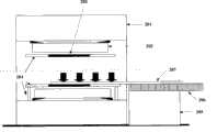
图3为本实用新型所述病床装置应用于磁共振系统中的第一实施例的组成结构示意图;Fig. 3 is a schematic diagram of the composition and structure of the first embodiment of the hospital bed device described in the present invention applied to the magnetic resonance system;
图4为本实用新型所述病床装置应用于磁共振系统中的第二实施例的组成结构示意图。Fig. 4 is a schematic diagram of the composition and structure of the second embodiment of the hospital bed device of the present invention applied to the magnetic resonance system.
具体实施方式Detailed ways
为了使本实用新型的目的、技术方案及优点更加清楚明白,以下结合附图及实施例,对本实用新型进行进一步详细说明。应当理解,此处所描述的具体实施例仅仅用以解释本实用新型,并不用于限定本实用新型。In order to make the purpose, technical solution and advantages of the utility model clearer, the utility model will be further described in detail below in conjunction with the accompanying drawings and embodiments. It should be understood that the specific embodiments described here are only used to explain the utility model, and are not intended to limit the utility model.
为解决现有技术中存在的问题,本实用新型实施例中提出一种应用于磁共振系统中的病床装置,采用独立浮动实现方式:在扫描过程中,将床板和梯度线圈固定在不同的物体上。所述病床装置包括床板以及支撑床板的支撑装置,在扫描过程中,支撑装置支撑床板穿过体线圈,与体线圈无接触。In order to solve the problems existing in the prior art, the embodiment of the utility model proposes a hospital bed device applied in the magnetic resonance system, which adopts an independent floating realization method: during the scanning process, the bed board and the gradient coil are fixed on different objects superior. The hospital bed device includes a bed board and a support device supporting the bed board. During the scanning process, the support device supports the bed board to pass through the body coil without contact with the body coil.
在实际应用中,上述病床装置可具体表现为多种不同的形式。下面通过具体的实施例,对本实用新型所述方案作进一步地详细说明:In practical application, the above-mentioned hospital bed device can be embodied in many different forms. Below by specific embodiment, described scheme of the utility model is described in further detail:
图3为本实用新型所述病床装置应用于磁共振系统中的第一实施例的组成结构示意图。如图3所示,本实施例中的磁共振系统主要包括:磁体301、梯度线圈302、体线圈303、体线圈孔管309等现有组成部分以及病床装置(其它不相关组成部分未图示);其中,病床装置中进一步包括:第一支架304、第二支架305、驱动机构306、床板307以及运行轨道308。其中,第一支架304、第二支架305、驱动机构306以及运行轨道308可统称为床板307的支撑装置。Fig. 3 is a schematic diagram of the composition and structure of the first embodiment of the application of the hospital bed device in the present invention to the magnetic resonance system. As shown in Figure 3, the magnetic resonance system in this embodiment mainly includes: existing components such as
第一支架304和第二支架305分别位于磁体301的两侧,与磁体301无接触,即独立于梯度线圈302,第一支架304和第二支架305可固定在地面上,分别用于支撑床板307的运行轨道308的两端;该运行轨道308与体线圈303之间具有一定的间隙,无接触;驱动机构306驱动床板307在运行轨道308上移动。如图3所示,驱动机构306可位于第一支架304与运行轨道308之间。The
采用图3所示实现方式后,由于床板由两个独立于磁体的支架进行支撑,不与任何产生振动的物体接触,这样,梯度线圈的振动就不会被传送到床板上,从而可以完全消除梯度线圈与床板之间的机械振动,进而避免了引起床板上所承载的被扫描物体的振动,提高了成像质量。After adopting the implementation shown in Figure 3, since the bed board is supported by two brackets independent of the magnets, and does not contact any vibration-generating objects, the vibration of the gradient coil will not be transmitted to the bed board, thereby completely eliminating The mechanical vibration between the gradient coil and the bed board avoids the vibration of the object to be scanned carried on the bed board, thereby improving the imaging quality.
图4为本实用新型所述病床装置应用于磁共振系统中的第二实施例的组成结构示意图。如图4所示,本实施例中的磁共振系统主要包括:磁体401、梯度线圈402、体线圈403、体线圈孔管410等现有组成部分以及病床装置(其它不相关组成部分未图示);其中,病床装置中进一步包括:第一支架404、第二支架405、第一驱动机构406、第二驱动机构407、支撑部件409以及床板408。其中,第一支架404、第二支架405、第一驱动机构406、第二驱动机构407以及支撑部件409可统称为床板408的支撑装置。第一支架404和第二支架405分别位于磁体401两侧,与磁体401无接触,即独立于梯度线圈402;第一支架404和第二支架405可固定在地面上。Fig. 4 is a schematic diagram of the composition and structure of the second embodiment of the hospital bed device of the present invention applied to the magnetic resonance system. As shown in Figure 4, the magnetic resonance system in this embodiment mainly includes: existing components such as a
第一驱动机构406驱动床板408在水平方向上沿体线圈403的轨道进行移动,并在当支撑部件409进入到床板408一端的底部时,驱动第一支架404升高,将床板408的另一端升高到预定的高度,与体线圈403之间具有一定的间隙;The
支撑部件409与第二支架405位于同侧,当床板408沿体线圈403的轨道移动至成像位置时,在第二驱动机构407的驱动下进入到床板408一端的底部,并在第二支架405的支撑下升高到预定的高度;The
第二驱动机构407当床板408沿体线圈403的轨道移动至成像位置时,驱动支撑部件409进入到床板408一端的底部,并驱动第二支架405升高,将支撑部件409及其上的床板408升高到预定的高度,与体线圈403之间具有一定的间隙。When the second driving mechanism 407 moves the
如图4所示,第一驱动机构406和第二驱动机构407可分别位于第一支架404和第二支架405之上。但在实际应用中,也可以采用其它的实现方式,比如,将第一驱动机构406以及第二驱动机构407分别设置在对应支架的内部,总之,具体实现方式不限。而且,本领域技术人员根据本领域常用技术手段,能够获知如何具体实现本实施例中所述的第一驱动机构406以及第二驱动机构407的功能。另外,本实施例中的驱动机构驱动支架上升或下降的方式可以是采用现有的气动或液压等方式。再有,本实施例中的支撑部件409可如图4所示,固定在第二驱动机构407上,可以将支撑部件409看成第二驱动机构407的一部分。当第二支架405上升时,支撑部件409同时上升。该支撑部件409可采用不锈钢等材料制成,需要足够坚硬以能够支持床板的最大负载。As shown in FIG. 4 , the
图4所示病床装置的具体工作流程包括:当需要进行扫描时,第一驱动机构406驱动床板408按现有方式沿水平方向在体线圈403的轨道上进行移动;当移动至成像位置时,位于第二驱动机构407处的一个小的支撑部件409在第二驱动机构407的驱动下进入到床板408的底部;之后,第一驱动机构406和第二驱动机构407分别驱动所述第一支架404和第二支架405升高若干毫米,该升高高度可预先设定,但需要保证两边升高高度一致,从而使床板408在进行扫描时处于悬浮状态。当扫描结束,床板408移出磁体时,第一驱动机构406还可以驱动第一支架404在垂直方向上下降或上升,以方便之后被扫描的物体,比如病人上到床板408上进行下一次扫描。The specific workflow of the hospital bed device shown in FIG. 4 includes: when scanning is required, the
采用图4所示实现方式后,由于在扫描过程中,床板成为完全的悬浮状态,与体线圈是游离的,即无机械接触,所以梯度线圈的振动不会被传送到床板上,提高了成像质量。After adopting the implementation shown in Figure 4, since the bed board becomes completely suspended during the scanning process and is free from the body coil, that is, there is no mechanical contact, so the vibration of the gradient coil will not be transmitted to the bed board, which improves imaging. quality.
总之,采用本实用新型实施例的技术方案,可以避免梯度线圈的振动对床板的影响,提高扫描时的成像质量,从而获得高分辨率,如像素大小小于0.1毫米的磁共振图像,这在场强为3T、4T或7T等情况时非常可能。另外,可以避免由于在振动时组织的弹性性能所引起的失相所造成的信号缺失。In a word, adopting the technical scheme of the embodiment of the utility model can avoid the influence of the vibration of the gradient coil on the bed plate, improve the imaging quality during scanning, and obtain high-resolution magnetic resonance images such as a pixel size smaller than 0.1 mm. It is very possible when the strength is 3T, 4T or 7T. In addition, loss of signal due to dephasing caused by the elastic properties of tissue upon vibration can be avoided.
需要说明的是,上述实施例仅用于举例说明,并不用于限制本实用新型的技术方案。凡在本实用新型的精神和原则之内所作的任何修改、等同替换和改进等,均应包含在本实用新型的保护范围之内。It should be noted that the above-mentioned embodiments are only used for illustration, and are not intended to limit the technical solution of the present utility model. All modifications, equivalent replacements and improvements made within the spirit and principles of the present utility model shall be included in the protection scope of the present utility model.
Claims (8)
Priority Applications (2)
| Application Number | Priority Date | Filing Date | Title |
|---|---|---|---|
| CNU2008200015651UCN201150537Y (en) | 2008-01-29 | 2008-01-29 | Sick bed applied in magnetic resonance system |
| US12/321,908US7924008B2 (en) | 2008-01-29 | 2009-01-27 | Vibrationally decoupled patient table for use in magnetic resonance system |
Applications Claiming Priority (1)
| Application Number | Priority Date | Filing Date | Title |
|---|---|---|---|
| CNU2008200015651UCN201150537Y (en) | 2008-01-29 | 2008-01-29 | Sick bed applied in magnetic resonance system |
Publications (1)
| Publication Number | Publication Date |
|---|---|
| CN201150537Ytrue CN201150537Y (en) | 2008-11-19 |
Family
ID=40126223
Family Applications (1)
| Application Number | Title | Priority Date | Filing Date |
|---|---|---|---|
| CNU2008200015651UExpired - Fee RelatedCN201150537Y (en) | 2008-01-29 | 2008-01-29 | Sick bed applied in magnetic resonance system |
Country Status (2)
| Country | Link |
|---|---|
| US (1) | US7924008B2 (en) |
| CN (1) | CN201150537Y (en) |
Cited By (2)
| Publication number | Priority date | Publication date | Assignee | Title |
|---|---|---|---|---|
| CN105816174A (en)* | 2015-01-08 | 2016-08-03 | 西门子(深圳)磁共振有限公司 | Magnetic resonance device |
| CN107257658A (en)* | 2015-02-27 | 2017-10-17 | 皇家飞利浦有限公司 | Magnetic resonance examination system with movable patient carrier |
Families Citing this family (3)
| Publication number | Priority date | Publication date | Assignee | Title |
|---|---|---|---|---|
| ITTO20070840A1 (en)* | 2007-11-23 | 2009-05-24 | Paramed Medical Systems S R L | POSITIONING SYSTEM FOR MEDICAL EQUIPMENT, AND IMAGING EQUIPMENT WITH MAGNETIC RESONANCE INCLUDING SUCH A SYSTEM |
| CN201150537Y (en)* | 2008-01-29 | 2008-11-19 | 西门子(中国)有限公司 | Sick bed applied in magnetic resonance system |
| CN103656870A (en)* | 2013-12-19 | 2014-03-26 | 李健 | Infrared physiotherapy instrument used for sickbed table |
Family Cites Families (7)
| Publication number | Priority date | Publication date | Assignee | Title |
|---|---|---|---|---|
| JP3891810B2 (en)* | 2001-09-28 | 2007-03-14 | ジーイー・メディカル・システムズ・グローバル・テクノロジー・カンパニー・エルエルシー | Magnetic resonance imaging device |
| US7218106B2 (en)* | 2003-12-04 | 2007-05-15 | Kabushiki Kaisha Toshiba | MRI with automatic contour-controlled separation between RF coil and object being imaged |
| WO2007061099A1 (en)* | 2005-11-25 | 2007-05-31 | Kabushiki Kaisha Toshiba | Medical image diagnosis device, medical image storage communication system server, image reference device, and medical image diagnosis system |
| JP4945134B2 (en)* | 2006-01-19 | 2012-06-06 | 株式会社東芝 | Magnetic resonance imaging system |
| JP2008253410A (en)* | 2007-04-02 | 2008-10-23 | Toshiba Corp | MRI apparatus and MRI bed apparatus |
| EP2174161B1 (en)* | 2007-07-25 | 2015-03-25 | Koninklijke Philips N.V. | Mr/pet imaging systems |
| CN201150537Y (en)* | 2008-01-29 | 2008-11-19 | 西门子(中国)有限公司 | Sick bed applied in magnetic resonance system |
- 2008
- 2008-01-29CNCNU2008200015651Upatent/CN201150537Y/ennot_activeExpired - Fee Related
- 2009
- 2009-01-27USUS12/321,908patent/US7924008B2/ennot_activeExpired - Fee Related
Cited By (2)
| Publication number | Priority date | Publication date | Assignee | Title |
|---|---|---|---|---|
| CN105816174A (en)* | 2015-01-08 | 2016-08-03 | 西门子(深圳)磁共振有限公司 | Magnetic resonance device |
| CN107257658A (en)* | 2015-02-27 | 2017-10-17 | 皇家飞利浦有限公司 | Magnetic resonance examination system with movable patient carrier |
Also Published As
| Publication number | Publication date |
|---|---|
| US7924008B2 (en) | 2011-04-12 |
| US20090189608A1 (en) | 2009-07-30 |
Similar Documents
| Publication | Publication Date | Title |
|---|---|---|
| CN201150537Y (en) | Sick bed applied in magnetic resonance system | |
| EP2315432A3 (en) | Image stabilizer | |
| JP6104505B2 (en) | Magnetic resonance imaging system | |
| CN204925368U (en) | A radio frequency emission coil and magnetic resonance imaging equipment for magnetic resonance imaging equipment | |
| CN1604240A (en) | Permanent magnet assembly with movable permanent body for main magnetic field adjustable | |
| JP6139064B2 (en) | Magnetic resonance imaging apparatus and magnetic field adjustment tool for magnetic resonance imaging apparatus | |
| JP2012123140A (en) | Actuator, optical scanner and image forming device | |
| KR20130055538A (en) | Gradient-independent shim coil for a local coil of a magnetic resonance device | |
| US8604794B2 (en) | Permanent magnet arrangement with solid facing plate and scanning magnet head | |
| CN107257658B (en) | Magnetic resonance examination system with movable patient carrier | |
| CN1548982A (en) | Magnetostatic field regulating method in magnetic resonance equipment and magnetostatic field generating apparatus thereof | |
| JP2015000165A (en) | Magnetic resonance imaging apparatus, and bed for imaging apparatus | |
| JP5972633B2 (en) | Top plate for magnetic resonance imaging apparatus and magnetic resonance imaging apparatus | |
| JP2010284233A (en) | Magnetic resonance imaging apparatus | |
| WO2006036946A3 (en) | Magnetic resonance imaging system, apparatus and associated methods | |
| CN113009394B (en) | Static magnetic field generating device | |
| US20160270690A1 (en) | Magnetic resonance imaging apparatus | |
| CN109596299A (en) | The dual-purpose shake table of vertical-horizontal | |
| CN109121063A (en) | A kind of equipment adjusting moving iron unit magnetic balance | |
| CN104146710A (en) | Magnetic resonance imaging device capable of generating non-spherical even-field-region magnetic fields | |
| CN204758650U (en) | Circuit board test needle bed from dynamic positioning device | |
| CN115079070A (en) | Magnetic field distribution control method based on nuclear magnetic resonance | |
| CN115046716A (en) | High-frequency standard vibration table | |
| CN116338542B (en) | Transmitting coil vibration reduction supporting device capable of being accurately adjusted | |
| CN207710997U (en) | A kind of non-burning brick framed positioning device |
Legal Events
| Date | Code | Title | Description |
|---|---|---|---|
| C14 | Grant of patent or utility model | ||
| GR01 | Patent grant | ||
| ASS | Succession or assignment of patent right | Owner name:SIEMENS MINDIT (SHENZHEN) MAGNETIC RESONANCE CO., Free format text:FORMER OWNER: SIEMENS (CHINA) AG Effective date:20090605 | |
| C41 | Transfer of patent application or patent right or utility model | ||
| TR01 | Transfer of patent right | Effective date of registration:20090605 Address after:Two SIEMENS magnetic resonance garden, Gaoxin District, Shenzhen hi tech Zone, Guangdong, China: 518057 Patentee after:Siemens Mindit (Shenzhen) Magnetic Resonance Ltd. Address before:No. 7, South Central Road, Wangjing, Beijing, Chaoyang District: 100102 Patentee before:Simens Co., Ltd. (China) | |
| C56 | Change in the name or address of the patentee | Owner name:SIEMENS (SHENZHEN) MAGNETIC RESONANCE CO., LTD. Free format text:FORMER NAME: SIEMENS MINDIT (SHENZHEN) MAGNETIC RESONANCE LTD. | |
| CP01 | Change in the name or title of a patent holder | Address after:518057 two SIEMENS magnetic resonance garden, central high tech Zone, Guangdong, Shenzhen Patentee after:Siemens (Shenzhen) Magnetic Resonance Ltd. Address before:518057 two SIEMENS magnetic resonance garden, central high tech Zone, Guangdong, Shenzhen Patentee before:Siemens Mindit (Shenzhen) Magnetic Resonance Ltd. | |
| CF01 | Termination of patent right due to non-payment of annual fee | Granted publication date:20081119 Termination date:20170129 | |
| CF01 | Termination of patent right due to non-payment of annual fee |