CN201112909Y - electrical connector - Google Patents
electrical connectorDownload PDFInfo
- Publication number
- CN201112909Y CN201112909YCNU2007201775239UCN200720177523UCN201112909YCN 201112909 YCN201112909 YCN 201112909YCN U2007201775239 UCNU2007201775239 UCN U2007201775239UCN 200720177523 UCN200720177523 UCN 200720177523UCN 201112909 YCN201112909 YCN 201112909Y
- Authority
- CN
- China
- Prior art keywords
- electrical connector
- insulating body
- groove
- cover
- electronic card
- Prior art date
- Legal status (The legal status is an assumption and is not a legal conclusion. Google has not performed a legal analysis and makes no representation as to the accuracy of the status listed.)
- Expired - Fee Related
Links
Images


Classifications
- H—ELECTRICITY
- H01—ELECTRIC ELEMENTS
- H01R—ELECTRICALLY-CONDUCTIVE CONNECTIONS; STRUCTURAL ASSOCIATIONS OF A PLURALITY OF MUTUALLY-INSULATED ELECTRICAL CONNECTING ELEMENTS; COUPLING DEVICES; CURRENT COLLECTORS
- H01R13/00—Details of coupling devices of the kinds covered by groups H01R12/70 or H01R24/00 - H01R33/00
- H01R13/62—Means for facilitating engagement or disengagement of coupling parts or for holding them in engagement
- H01R13/629—Additional means for facilitating engagement or disengagement of coupling parts, e.g. aligning or guiding means, levers, gas pressure electrical locking indicators, manufacturing tolerances
Landscapes
- Coupling Device And Connection With Printed Circuit (AREA)
Abstract
Translated fromChinese
Description
Translated fromChinese【技术领域】【Technical field】
本实用新型涉及一种电连接器,尤其是一种用于收容电子卡并具有退卡机构的电连接器。The utility model relates to an electrical connector, in particular to an electrical connector used for accommodating electronic cards and having a card ejecting mechanism.
【背景技术】【Background technique】
随着电子设备的迅速发展,其体积日趋小型化,从而促使其信号传输装置也向更小、更轻且更宜携带的方向发展,这对应用于该电子设备上的电连接器也提出了更高的要求。台湾TW 288980号专利揭露一种电连接器,用于收容电子卡。该电连接器包括绝缘本体、收容于绝缘本体内的若干导电端子、覆盖在绝缘本体上的盖体和安装于绝缘本体内的退卡机构。With the rapid development of electronic equipment, its volume is becoming smaller and smaller, which promotes the development of its signal transmission device in a smaller, lighter and more portable direction. higher requirement. Taiwan's TW 288980 patent discloses an electrical connector for accommodating electronic cards. The electrical connector includes an insulating body, a plurality of conductive terminals accommodated in the insulating body, a cover covering the insulating body and a card ejecting mechanism installed in the insulating body.
该退卡机构包含推杆、传动杆和推动机构。当按压推动机构时,该推动机构会带动传动杆推动推杆运动,利用推杆将电子卡退出于电连接器外。该推动机构内设有弹簧,且该推动机构可提供给电子卡的退出力较大。The card ejection mechanism includes a push rod, a transmission rod and a push mechanism. When the push mechanism is pressed, the push mechanism will drive the transmission rod to push the push rod to move, and the push rod will withdraw the electronic card from the electrical connector. The pushing mechanism is provided with a spring, and the pushing mechanism can provide a relatively large withdrawal force for the electronic card.
基于上面叙述可见,当按压推动结构时,由于该退卡机构提供给电子卡的退出力较大,电子卡会立即退出于电连接器,这样可能出现电子卡瞬时喷出于电连接器的现象。然而,当电子卡拔出时,该电连接器也没有提供防止数据丢失的功能。Based on the above description, it can be seen that when the push structure is pressed, the electronic card will immediately withdraw from the electrical connector due to the large withdrawal force provided by the card ejection mechanism to the electronic card, so that the electronic card may be ejected from the electrical connector instantaneously. . However, this electrical connector also provides no protection against data loss when the electronic card is pulled out.
为了避免上述问题,本实用新型提出了一种新的电连接器以弥补其不足。In order to avoid the above problems, the utility model proposes a new electrical connector to make up for its shortcomings.
【实用新型内容】【Content of utility model】
本实用新型的目的在于提供防止电子卡瞬时喷出的电连接器。The purpose of the utility model is to provide an electrical connector that prevents the electronic card from being ejected instantaneously.
本实用新型的另一个目的在于提供延长电子卡退出时间以防止数据丢失的电连接器。Another object of the present invention is to provide an electrical connector that prolongs the ejection time of the electronic card to prevent data loss.
为实现上述目的,本实用新型采用了一种电连接器,用于收容电子卡,包括绝缘本体、收容于绝缘本体内的若干导电端子、容置于绝缘本体内的滑动件、一端固持于绝缘本体上另一端固持于滑动件上的弹簧、一端枢接于绝缘本体上另一端枢接于滑动件上的引导件、盖接于绝缘本体上的盖体和固持于绝缘本体上可与盖体搭接的侦测端子,所述滑动件上设有凸起部,凸起部上设有固持槽,盖体上设有可与该固持槽抵顶的第二弹片。In order to achieve the above purpose, the utility model adopts an electrical connector for accommodating an electronic card, including an insulating body, a number of conductive terminals accommodated in the insulating body, a sliding piece accommodated in the insulating body, and one end held on the insulating body. The other end on the main body is fixed on the spring on the slider, one end is pivotally connected to the guide on the insulating body and the other end is pivotally connected to the sliding member, the cover is connected to the insulating body and the cover is fixed on the insulating body and can be connected with the cover. For the overlapping detection terminal, the sliding part is provided with a raised part, the raised part is provided with a holding groove, and the cover is provided with a second elastic piece which can abut against the holding groove.
与现有技术相比,本实用新型电连接器,在电子卡拔出时,电子卡会带动滑动件沿插卡方向反向运动。借助盖体的第二弹片抵顶于滑动件的固持槽上,延长电子卡退出电连接器的时间。另外,由于延长了电子卡退出电连接器的时间,使得侦测端子有足够的时间与盖体断开并接通记忆体保持回路,防止数据丢失。Compared with the prior art, in the electrical connector of the utility model, when the electronic card is pulled out, the electronic card will drive the sliding part to move in reverse along the card insertion direction. The time for the electronic card to withdraw from the electrical connector is prolonged by means of the second elastic piece of the cover abutting against the holding groove of the slider. In addition, since the time for the electronic card to withdraw from the electrical connector is prolonged, the detection terminal has enough time to disconnect from the cover and connect to the memory holding circuit to prevent data loss.
【附图说明】【Description of drawings】
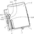
图1为本实用新型电连接器的立体图。FIG. 1 is a perspective view of the electrical connector of the present invention.
图2为本实用新型电连接器电子卡未插入时且去掉盖体的立体图。Fig. 2 is a perspective view of the electrical connector of the present invention when the electronic card is not inserted and the cover is removed.
图3为本实用新型电连接器电子卡完全插入时且去掉盖体的立体图。Fig. 3 is a perspective view of the electric connector of the present invention when the electronic card is fully inserted and the cover is removed.
图4为本实用新型电连接器电子卡被部分退出时且去掉盖体的立体图。Fig. 4 is a perspective view of the electronic card of the electrical connector of the present invention when it is partially withdrawn and the cover is removed.
图5为本实用新型电连接器电子卡被部分退出时且去掉盖体另一视角的立体图。FIG. 5 is a perspective view from another perspective when the electronic card of the electrical connector of the present invention is partially withdrawn and the cover is removed.
图6为本实用新型电连接器去掉盖体的立体图。Fig. 6 is a perspective view of the electrical connector of the present invention without the cover.
图7为本实用新型电连接器中绝缘本体的立体图。FIG. 7 is a perspective view of the insulating body in the electrical connector of the present invention.
图8为本实用新型电连接器中绝缘本体另一视角的立体图。FIG. 8 is a perspective view from another perspective of the insulating body in the electrical connector of the present invention.
图9为本实用新型电连接器中盖体的立体图。FIG. 9 is a perspective view of the cover in the electrical connector of the present invention.
图10为本实用新型电连接器中滑动件的底面立体图。Fig. 10 is a perspective view of the bottom surface of the slider in the electrical connector of the present invention.
图11为本实用新型电连接器中滑动件的立体图。Fig. 11 is a perspective view of the sliding part in the electrical connector of the present invention.
图12为本实用新型电连接器中滑动件另一视角的立体图。Fig. 12 is a perspective view of another angle of view of the slider in the electrical connector of the present invention.
图13为本实用新型电连接器中侦测端子的立体图。FIG. 13 is a perspective view of the detection terminal in the electrical connector of the present invention.
图14为本实用新型电连接器中引导件的立体图。Fig. 14 is a perspective view of the guide in the electrical connector of the present invention.
图15为本实用新型电连接器电子卡即将完全插入时的立体图。Fig. 15 is a perspective view of the electronic card of the electrical connector of the present invention when it is about to be fully inserted.
【具体实施方式】【Detailed ways】
请参阅图1至图15所示,本实用新型公开一种电连接器100,用于收容电子卡2,其包括设有收容部10和保持部11的绝缘本体1,收容于绝缘本体1的收容部10内的若干导电端子8、被绝缘本体1的保持部11支撑并可引导电子卡2移动的滑动件4,收容于绝缘本体1内并可与滑动件4弹接的弹簧6、用于引导滑动件4在保持部11内滑动的引导件5、收容于绝缘本体1内的侦测端子7和扣合在绝缘本体1上的盖体3。1 to 15, the utility model discloses an electrical connector 100 for accommodating an
电子卡2大致呈矩形,其包括弹接部21,该弹接部21上设有可与滑动件4弹接的凸出部212和开口槽214,凸出部212上设有倾斜面2120,该倾斜面2120可与滑动件4上对应的部分抵接,方便电子卡2插入电连接器100内。The
如图7和图8所示,绝缘本体1大致呈一矩形板状,其包括前壁12、侧壁13和由前壁12和侧壁13围设成的本体部(未标示)。该本体部设有可收容导电端子8的收容部10和支撑滑动体4的保持部11。前壁12设有用以套设弹簧6的定位栓120、用来收容侦测端子7的凹槽124和位于前壁12和侧壁13转角处(未标示)的平台122。该平台122上设有用于收容引导件5一端的定位孔1220。保持部11为用于收容滑动件4并具底面111的腔体(未标示)。底面111上定义有沟槽110,该沟槽110由第一沟槽1101和与第一沟槽1101呈角度设置用于引导滑动件4在腔体内滑动的第二沟槽1102组成。凹槽124则由上槽1243、下槽1245和中心槽1244组成。侧壁13设有直立壁131、自直立壁131延伸的倾斜壁132和连接倾斜壁132的尾端133。倾斜壁132可引导滑动件4在保持部11内沿预设的轨迹滑动。保持部11进一步设有连接于尾端133用于抵靠滑动件4的凸出体112和与该凸出体112邻接的开口116。As shown in FIG. 7 and FIG. 8 , the
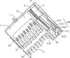
导电端子8收容于绝缘本体1的收容部10内。The
请参阅图2和图10-12所示,滑动件4设有基部40、从基部40的一端向上延伸的支撑部41、自基部40延伸并与基部40相对设置的凸起部42和形状与电子卡2的凸出部212一致夹在支撑部41和凸起部42间用于引导电子卡2在绝缘本体1内滑动的凹部43。该凹部43上设有引导面430,该引导面430用于和电子卡2上的倾斜面2120接触,从而引导电子卡2的插入。支撑部41设有狭槽410,该狭槽410可将弹簧6部分收容于其内。凸起部42上设有固持槽421和配合部420,当电子卡2插入绝缘本体1时,该配合部420可与电子卡2的开口槽214相配。基部40设有用于引导引导件5滑动的引导槽401,借助此引导槽401可使与滑动件4配合的电子卡2沿着预设轨迹滑动。该引导槽401包括平滑的第一引导槽4011、连接于第一引导槽4011弯折的平滑的第二引导槽4012和连接第一引导槽4011和第二引导槽4012的第三引导槽4013。第二引导槽4012大致呈V形,用于延长电子卡2退出电连接器100的时间。第一、第二、第三引导槽4011、4012、4013彼此相连,形成循环渠用以引导引导件5的滑动。第一、第二、第三引导槽4011、4012、4013的高度呈负增长的趋势,这样有利于引导件5围绕于其内滑动。当将电子卡2插入电连接器100内时,引导件5自初始位置在第一引导槽4011内滑动,当引导件5位于初始位置时,弹簧6自然张开。当电子卡2被拔出时,引导件5滑入呈V形的第二引导槽4012内,随后再滑入第三引导槽4013。当电子卡2完全退出时,引导件5的引导部51则回复至初始位置。另外,滑动件4还设有底部44,该底部44设有可插入于保持部11的沟槽110内的插入部440和与凸出体112配合的凹形部442。2 and shown in FIGS. 10-12 , the
引导件5为弯曲的杆件,其包括连接部50和自连接部50的两端呈角度设置的定位部52和引导部51。定位部52可插入于绝缘本体1的前壁12上的定位孔1220内;引导部51可插入于滑动件4的引导槽401内,用以引导滑动件4滑动。The
弹簧6收容于滑动件4的狭槽410内,其可利用自身的弹力驱动滑动件4在保持部11内于初始位置和第二位置间滑动。这里,初始位置指当弹簧6未被按压时滑动件4和引导件5所处的位置,第二位置指电子卡2在绝缘本体1内移动时,弹簧6被按压至最短长度时,滑动件4和引导件5所处的位置。The
如图9所示,盖体3扣合在绝缘本体1上并与绝缘本体1共同形成有收容电子卡2的收容空间(未标示),盖体3包括平板基体30、后墙32和自后墙32延伸的两个相对设置的侧墙31,该基体30、后墙32和侧墙31共同形成可收容绝缘本体1的收容腔(未标示)。盖体3上还设有连接于基体30并盖接于滑动件4的第一窗口304、第二窗口308,分别于第一窗口304和第二窗口308一体冲压而成的第一弹片302和第二弹片306。第一弹片302和第二弹片306均与侧墙31相连,借此弹性靠压收容于绝缘本体1内的滑动件4。盖体3上设有一可使基体30和后墙32相通的开口300,于开口300上冲压成型有用于和侦测端子7接触的盖接端子301。第一弹片302包括有与盖体3相连的连接片3020和自该连接片3020延伸的可与滑动件4抵接的延伸片3022。第二弹片306包括连接盖体3的主体片3060和自主体片3060延伸用于压接滑动件4的弧形弹片3062。该弧形弹片3062可抵接到滑动件4的凸起部42上的固持槽421内,用于防止电子卡2的瞬时喷出。当电子卡2被拔出时,主体片3060和弧形弹片3062分别与滑动件4抵接,借此降低电子卡2退出速度。盖接端子301包括自基体30延伸的本体部3010、自本体部3010向下倾斜延伸的弯曲部3012和与侦测端子7弹性接触的弹接部3014。As shown in Figure 9, the
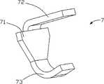
于绝缘本体1的前壁12上安装有侦测端子7,该侦测端子7用来监测电子卡2是否完全装入电连接器100内。当电子卡2完全插入电连接器100内,侦测端子7将与盖体3断开,而当电子卡2退出于电连接器100内,侦测端子7将与盖体3接触。如图7所示,侦测端子7包括有三角状的可插入绝缘本体1的中心槽1244内的插入部71,自插入部71一端延伸可收容于绝缘本体1的上槽1243内用于和盖体3接触的抵接尾端72和自插入部71的另一端延伸可收容于绝缘本体1的下槽1245内用于焊接至印刷电路板上的焊接尾端73。A
导电端子8收容于绝缘本体1的收容部10内,其包括基体部81、自基体部81一端延伸的接触部82和自基体部81另一端延伸的焊接部83。The
组装时,首先将带有弹簧6和引导件5的滑动件4装入绝缘本体的保持部11内,这时弹簧6的一端收容于滑动件4的狭槽410,另一端抵接于绝缘本体1的前壁12的定位栓120上。引导件5收容于绝缘本体1的保持部11内,具体为引导件5上的定位部52收容于绝缘本体1上的定位孔1220,与此同时,引导件5的引导部51收容于引导件5的引导槽401内。接着,将导电端子8插入于绝缘本体1的收容部10内,然后将侦测端子7插入于绝缘本体1的前壁12上的中心槽1244内。最后将盖体3盖接于绝缘本体1上,这时,侦测端子7的抵接尾端72与盖体3的弹接部3014弹接。当电子卡2插入于电连接器内时,侦测端子7与盖体分离。When assembling, first put the
电子卡2的插入:用力将电子卡2沿插卡方向推入电连接器100内,电子卡2弹接部21的凸出部212开始和滑动件4的凹部43抵接,然后电子卡2的开口槽214与滑动件4的配合部420抵接。这时,弹簧6处于未被按压的常态,引导件5处于初始位置,当进一步推动电子卡2时,滑动件4受到电子卡2上的弹接部21的推动而向绝缘本体1的前壁12运动,弹簧6被沿着滑动件4运动的方向按压,引导件5自初始位置沿着第一引导槽4011滑动。当电子卡2完全插入于电连接器100内时,引导件5处于第二引导槽4012的附近。Insertion of the electronic card 2: push the
电子卡2的弹出:用手抓住电子卡2,电子卡2会带动滑动件4沿插卡方向反向运动。引导件5也在滑动件4的带动下沿第二、第三引导槽4012、4013滑动。借助滑动件4的配合部420抵接于电子卡2的开口槽214内,以及盖体3的第二弹片306抵顶于滑动件4的凸起部42的固持槽421,延长电子卡2退出电连接器100的时间。另外,侦测端子7与盖接端子301的弹接部3014断开,同时接通记忆体保持回路,防止当电子卡2和导电端子8脱离时,应用这种电子卡2的电子设备数据丢失。由于延长了电子卡2退出电连接器的时间,使得侦测端子7有足够的时间与盖体3上的弹接部3014断开并接通记忆体保持回路。Ejection of the electronic card 2: hold the
需要指出的是,本实用新型电连接器不仅局限以上所述的具体结构。It should be pointed out that the electrical connector of the present invention is not limited to the specific structure described above.
Claims (8)
Translated fromChineseApplications Claiming Priority (2)
| Application Number | Priority Date | Filing Date | Title |
|---|---|---|---|
| US11/633,922 | 2006-12-05 | ||
| US11/633,922US7278866B1 (en) | 2006-12-05 | 2006-12-05 | Electrical card connector |
Publications (1)
| Publication Number | Publication Date |
|---|---|
| CN201112909Ytrue CN201112909Y (en) | 2008-09-10 |
Family
ID=38562072
Family Applications (1)
| Application Number | Title | Priority Date | Filing Date |
|---|---|---|---|
| CNU2007201775239UExpired - Fee RelatedCN201112909Y (en) | 2006-12-05 | 2007-09-29 | electrical connector |
Country Status (3)
| Country | Link |
|---|---|
| US (1) | US7278866B1 (en) |
| CN (1) | CN201112909Y (en) |
| TW (1) | TWM336568U (en) |
Cited By (1)
| Publication number | Priority date | Publication date | Assignee | Title |
|---|---|---|---|---|
| CN101976779A (en)* | 2010-11-08 | 2011-02-16 | 中航光电科技股份有限公司 | Connector capable of preventing pins from being damaged |
Families Citing this family (7)
| Publication number | Priority date | Publication date | Assignee | Title |
|---|---|---|---|---|
| JP2010056038A (en)* | 2008-08-29 | 2010-03-11 | Mitsumi Electric Co Ltd | Memory card connector |
| CN101673889B (en)* | 2008-09-09 | 2012-06-20 | 富士康(昆山)电脑接插件有限公司 | Electronic card connector |
| CN201774078U (en)* | 2010-07-21 | 2011-03-23 | 富士康(昆山)电脑接插件有限公司 | electronic card connector |
| US8262397B1 (en)* | 2011-04-19 | 2012-09-11 | Hon Hai Precision Ind. Co., Ltd. | Card ejector having a slider and a spring engaging a stopper on a metallic shell |
| TWI452775B (en)* | 2011-05-04 | 2014-09-11 | Hon Hai Prec Ind Co Ltd | Card connector |
| SG186517A1 (en)* | 2011-06-30 | 2013-01-30 | Molex Singapore Pte Ltd | Card connector |
| CN104916993B (en)* | 2014-03-12 | 2017-06-20 | 富士康(昆山)电脑接插件有限公司 | Electronic card coupler |
Family Cites Families (8)
| Publication number | Priority date | Publication date | Assignee | Title |
|---|---|---|---|---|
| US7077671B2 (en)* | 2004-08-24 | 2006-07-18 | Cheng Uei Precision Industry Co., Ltd. | Memory card connector with a push-push mechanism |
| CN2770148Y (en)* | 2004-12-21 | 2006-04-05 | 富士康(昆山)电脑接插件有限公司 | Electronic card connector |
| TW200627724A (en)* | 2005-01-24 | 2006-08-01 | Top Yang Technology Entpr Co | Metallic sliding slot structure for an electrical connector |
| TWI294198B (en)* | 2005-06-17 | 2008-03-01 | Hon Hai Prec Ind Co Ltd | Electrical card connector |
| TWI306322B (en)* | 2005-08-22 | 2009-02-11 | Hon Hai Prec Ind Co Ltd | Electrical card connector |
| US7175452B1 (en)* | 2005-09-23 | 2007-02-13 | Itw Tech. Co., Ltd. | Memory card connector |
| TWM289541U (en)* | 2005-11-07 | 2006-04-11 | Tai Sol Electronics Co Ltd | Connector ejection device assembly |
| US7192292B1 (en)* | 2006-03-03 | 2007-03-20 | Cheng Uei Precision Industry Co., Ltd. | Card connector having improved supporting structure for ejecting mechanism |
- 2006
- 2006-12-05USUS11/633,922patent/US7278866B1/ennot_activeExpired - Fee Related
- 2007
- 2007-09-29CNCNU2007201775239Upatent/CN201112909Y/ennot_activeExpired - Fee Related
- 2007-10-22TWTW096217630Upatent/TWM336568U/ennot_activeIP Right Cessation
Cited By (2)
| Publication number | Priority date | Publication date | Assignee | Title |
|---|---|---|---|---|
| CN101976779A (en)* | 2010-11-08 | 2011-02-16 | 中航光电科技股份有限公司 | Connector capable of preventing pins from being damaged |
| CN101976779B (en)* | 2010-11-08 | 2012-12-26 | 中航光电科技股份有限公司 | Connector capable of preventing pins from being damaged |
Also Published As
| Publication number | Publication date |
|---|---|
| TWM336568U (en) | 2008-07-11 |
| US7278866B1 (en) | 2007-10-09 |
Similar Documents
| Publication | Publication Date | Title |
|---|---|---|
| CN201112909Y (en) | electrical connector | |
| CN201112654Y (en) | card edge connector | |
| CN201112917Y (en) | electrical connector | |
| TWI382601B (en) | Electrical connector | |
| CN201112624Y (en) | electronic card connector | |
| KR100321552B1 (en) | Card connector assembly | |
| CN201430267Y (en) | electronic card connector | |
| CN100576649C (en) | electronic card connector | |
| CN201397958Y (en) | Electronic card connector | |
| CN100470954C (en) | electronic card connector | |
| CN201146263Y (en) | electronic card connector | |
| CN201207503Y (en) | Connector for electronic card | |
| CN201352650Y (en) | Card connector | |
| CN100546116C (en) | electronic card connector | |
| CN201112924Y (en) | electrical connector | |
| CN201112920Y (en) | card edge connector | |
| CN201142438Y (en) | card edge connector | |
| CN100448111C (en) | electronic card connector | |
| CN101728709B (en) | Electronic card connector | |
| CN101320852B (en) | electronic card connector | |
| CN2766381Y (en) | Electronic card connector | |
| CN202772351U (en) | Card connector and card connector and circuit board combination | |
| CN201829663U (en) | Electronic card connector | |
| CN202076592U (en) | Connector of electronic card | |
| CN201887187U (en) | Electronic card connector |
Legal Events
| Date | Code | Title | Description |
|---|---|---|---|
| C14 | Grant of patent or utility model | ||
| GR01 | Patent grant | ||
| CF01 | Termination of patent right due to non-payment of annual fee | Granted publication date:20080910 Termination date:20160929 | |
| CF01 | Termination of patent right due to non-payment of annual fee |