CN201110955Y - A medical infusion speed monitoring and control device based on machine vision - Google Patents
A medical infusion speed monitoring and control device based on machine visionDownload PDFInfo
- Publication number
- CN201110955Y CN201110955YCNU2007200888329UCN200720088832UCN201110955YCN 201110955 YCN201110955 YCN 201110955YCN U2007200888329 UCNU2007200888329 UCN U2007200888329UCN 200720088832 UCN200720088832 UCN 200720088832UCN 201110955 YCN201110955 YCN 201110955Y
- Authority
- CN
- China
- Prior art keywords
- speed
- data
- infusion
- drip
- data processor
- Prior art date
- Legal status (The legal status is an assumption and is not a legal conclusion. Google has not performed a legal analysis and makes no representation as to the accuracy of the status listed.)
- Expired - Fee Related
Links
Images


Landscapes
- Infusion, Injection, And Reservoir Apparatuses (AREA)
Abstract
Translated fromChinese
Description
Translated fromChinese技术领域technical field
本实用新型属于医疗器械领域,具体涉及一种基于机器视觉的医疗输液速度监测与控制装置,该装置可以配合医疗输液器械使用,是一种用于医院输液的辅助医疗设备。The utility model belongs to the field of medical equipment, in particular to a machine vision-based medical infusion speed monitoring and control device, which can be used in conjunction with medical infusion equipment, and is an auxiliary medical equipment for hospital infusion.
背景技术Background technique
静脉输液是临床治疗的一项常用给药治疗技术,是利用输液管内的液体压强比人体静脉血管内液体压强大的原理,将药液通过导管直接输入到人体静脉。在输液过程中,液体进入病患静脉的速度直接影响到药物对病患的治疗效果,速度过快,可能会导致病患中毒,严重时可至心力衰竭;速度过慢则可能发生药量不够或无谓地延长输液时间,使治疗效果受影响,增加医务人员的工作量,同时给患者带来不便。目前,医院中常规临床输液普遍采用传统的挂瓶输液的方式。挂瓶输液需要医护人员用眼睛观察,同时,需要医护人员凭经验和直觉根据医嘱和病患的情况手工来调整液滴速度。在传统的手动调节方式下,输液速度不易精确控制,调整误差大,并且在输液过程中速度还可能会出现波动。此外,传统的输液方式需要医护人员人工观测药物的剩余量,以便在药物用完时及时结束输液过程。若医务人员疏忽,没有在药物用完时及时停止,极有可能造成病人出现回血现象,而且,在传统的输液方式下,为避免在输液过程中因意外情况造成输液异常(如:针头脱出或堵塞),往往需要病人自己或者陪同人员或者医护人员时刻进行监视,这无疑会给病人增加痛苦,给病人家属以及医护人员增加负担。Intravenous infusion is a commonly used drug administration technology in clinical treatment. It uses the principle that the liquid pressure in the infusion tube is stronger than the liquid pressure in the human vein, and the medicinal liquid is directly injected into the human vein through the catheter. During the infusion process, the speed at which the liquid enters the patient's vein directly affects the therapeutic effect of the drug on the patient. If the speed is too fast, the patient may be poisoned, and in severe cases, it may lead to heart failure; if the speed is too slow, the dose may not be enough. Or prolong the infusion time unnecessarily, affect therapeutic effect, increase the workload of medical personnel, bring inconvenience to patient simultaneously. At present, conventional clinical infusion in the hospital generally adopts the traditional way of hanging bottle infusion. Hanging bottle infusion requires medical staff to observe with eyes, and at the same time, medical staff needs to use experience and intuition to manually adjust the droplet speed according to the doctor's order and the patient's condition. In the traditional manual adjustment mode, the infusion speed is not easy to be accurately controlled, the adjustment error is large, and the speed may fluctuate during the infusion process. In addition, the traditional infusion method requires medical staff to manually observe the remaining amount of the drug, so that the infusion process can be ended in time when the drug is used up. If the medical staff is negligent and fails to stop the drug in time when the drug is used up, it is very likely to cause the patient to return to blood. Moreover, in the traditional infusion method, in order to avoid abnormal infusion due to accidents during the infusion process (such as needle prolapse or Blockage), often requires the patient himself or his companions or medical staff to monitor at all times, which will undoubtedly increase the suffering of the patient and increase the burden on the patient's family members and medical staff.
为克服手工输液方式存在的上述缺陷,市面上出现了一些检测和控制输液速度的装置,但是这些装置都不十全十美,要么技术上还有欠缺,要么是成本偏高。输液速度的检测和控制从实现的技术手段上需要考虑一些因素,其中包括:(1)输液流速的有效检测。由于输液的速度受药液的浓度,导管材料特性及管壁光滑程度的影响,如何有效地检测流速是一个需考虑的因素。(2)输液流量精度的控制。如何达到控制流速的精度要求又能适当地控制设备的成本,也是一个需考虑的因素。(3)输液流量装置尺寸的控制。目前普遍采用的装置尺寸略微偏大,有些甚至采用分离装置实现,如何能改变结构,缩小装置尺寸也是一个值得考虑的因素。目前,关于医用输液速度检测和流量控制的专利也有很多,如公开号为CN2875460的专利文献采用了红外光收发器件,利用液体内对光具有折射的原理来对液体进行检测,这样的检测方法具有易实现的优点,但红外光收发装置容易受外界辐射源的干扰,且在莫非氏滴管上的安装红外检测设备工艺要求高,并对安装精确度有很高的要求。一旦滴管处于歪斜状态,传感器就不能准确地检测到下落的液滴。此外,还有部分专利文献中采用了称重原理作为限流装置,虽然该方法原理简单,易实现,但由于不同厂家生产的输液瓶和输液袋所采用的材料和工艺的不同,其重量存在着差异,从而对测量精度产生了一定的影响。如果每次设置时需要对重量参数做初始化处理,则增加了操作的复杂性。另外市场上也存在一些输液泵之类的设备,但因价格昂贵,大多仅限于在高端重症监护室(ICU)或手术室(OR)使用。In order to overcome the above-mentioned defects in the manual infusion method, some devices for detecting and controlling the infusion speed have appeared on the market, but these devices are not perfect, either technically deficient, or the cost is high. The detection and control of the infusion speed need to consider some factors in terms of technical means, including: (1) effective detection of the infusion flow rate. Since the infusion rate is affected by the concentration of the drug solution, the characteristics of the catheter material and the smoothness of the tube wall, how to effectively detect the flow rate is a factor that needs to be considered. (2) Control of infusion flow accuracy. How to achieve the accuracy requirement of controlling the flow rate and properly control the cost of the equipment is also a factor to be considered. (3) Control of the size of the infusion flow device. At present, the size of the commonly used devices is slightly too large, and some are even implemented with separate devices. How to change the structure and reduce the size of the device is also a factor worth considering. At present, there are also many patents on medical infusion speed detection and flow control. For example, the patent document with the publication number CN2875460 uses an infrared light transceiver device to detect the liquid by using the principle of refraction of light in the liquid. This detection method has the advantages of The advantages of easy implementation, but the infrared light transceiver device is easily interfered by external radiation sources, and the installation of infrared detection equipment on the Murphy's dropper requires high technology and high requirements for installation accuracy. Once the dropper is skewed, the sensor cannot accurately detect the falling droplet. In addition, there are some patent documents that use the principle of weighing as the current limiting device. Although the principle of this method is simple and easy to implement, due to the different materials and processes used in the infusion bottles and infusion bags produced by different manufacturers, the weight of the method may vary. The difference has a certain impact on the measurement accuracy. If the weight parameter needs to be initialized each time it is set, the complexity of the operation will be increased. In addition, there are also some devices such as infusion pumps on the market, but because of their high price, most of them are limited to use in high-end intensive care units (ICU) or operating rooms (OR).
发明内容Contents of the invention
本实用新型的目的在于提供一种基于机器视觉的医疗输液速度监测与控制装置,该装置能较准确地检测和控制输液的速度,并能对无药液状态等输液过程中可能出现的异常情况做出报警提示,有助于病人对药物的吸收和减少医护人员的护理工作量。The purpose of this utility model is to provide a medical infusion speed monitoring and control device based on machine vision. Making an alarm prompt helps the patient to absorb the medicine and reduces the nursing workload of the medical staff.
本实用新型提供的基于机器视觉的医疗输液速度监测与控制装置,其特征在于:该装置包括图像采集装置、参数输入装置、数据处理器、数据显示装置、滴速控制装置和报警提示装置;The medical infusion speed monitoring and control device based on machine vision provided by the utility model is characterized in that the device includes an image acquisition device, a parameter input device, a data processor, a data display device, a drip speed control device and an alarm prompt device;
参数输入装置、数据显示装置和报警提示装置安装在壳体的面板上,图像采集装置、数据处理器和滴速控制装置固定在壳体内部,壳体上设置有通孔,图像采集装置位于滴速控制装置的上方;The parameter input device, data display device and alarm prompt device are installed on the panel of the housing, the image acquisition device, data processor and drip speed control device are fixed inside the housing, and a through hole is arranged on the housing, and the image acquisition device is located in the dripping above the speed control device;
图像采集装置用于采集输液管的滴筒内滴液的图像数据,将采集的图像数据传输给数据处理器;The image acquisition device is used to collect image data of dripping liquid in the drip tube of the infusion tube, and transmit the collected image data to the data processor;
参数输入装置用于接收用户的输入,并将接收的信息分别传送给数据处理器;The parameter input device is used to receive the user's input, and transmit the received information to the data processor respectively;
数据处理器用于接收图像采集装置传送来的图像数据,根据接收到的图像数据计算药液的实时滴速,还接收参数输入装置传送来的期望滴速数据,并将其传输给数据显示装置,同时向数据显示装置传送要求将其显示给用户的控制指令;数据处理器将期望滴速数据和实测滴速数据进行比较和分析,得出两者之间的大小关系的信息,并根据该信息产生是否要求改变滴速的控制指令和/或相应的报警提示的控制指令,将控制指令分别发送给滴速控制装置和报警提示装置;The data processor is used to receive the image data sent by the image acquisition device, calculate the real-time dropping speed of the liquid medicine according to the received image data, and also receive the expected dropping speed data sent by the parameter input device, and transmit it to the data display device, At the same time, the data display device transmits the control command that requires displaying it to the user; the data processor compares and analyzes the expected drip speed data and the measured drip speed data, and obtains the information of the size relationship between the two, and according to the information Generate a control command for changing the drip speed and/or a corresponding alarm prompt, and send the control command to the drip speed control device and the alarm prompt device respectively;
数据显示装置用于接收数据处理器传送来的控制指令以及数据信息等,并按照控制指令将接收到的数据信息显示给用户;The data display device is used to receive control instructions and data information sent by the data processor, and display the received data information to the user according to the control instructions;
滴速控制装置通过驱动电路与数据处理器相连,用于接收数据处理器传送来的控制指令以及实测滴速与期望滴速差的绝对值数据信息,并按照该指令以及数据信息对滴速进行调整;The dripping speed control device is connected with the data processor through the driving circuit, and is used to receive the control instruction transmitted by the data processor and the absolute value data information of the difference between the measured dripping speed and the expected dripping speed, and perform the dripping speed adjustment according to the instruction and the data information. Adjustment;
报警提示装置用于接收数据处理器传送来的控制指令,并按照该控制指令产生相应的报警提示信息。The alarm prompting device is used for receiving the control instruction sent by the data processor, and generating corresponding alarm prompt information according to the control instruction.
本实用新型装置使用时,将输液滴管卡在采集罩背板和含有图像采集装置的采集罩中间,这样可保证图像采集装置和滴管的距离和角度不变,同时将采集罩背板正对图像采集装置的一面涂成单一颜色,使摄像头采集的图像具有单色的背景,可以减少复杂的背景噪音对采集信息的干扰。通过数据采集模块的快速地连续采集含液滴信息的图像数据,用以避免液滴漏检问题。单色的背景便于从图像数据中分析液滴形态从而进行准确计数,即便滴筒发生了倾斜,药液的密度和颜色发生了变化都不会对计数装置的计数精度产生影响。此装置设计上采用单侧采样的方式进行图像采样,以便于使用时的安装。本实用新型能较普遍采用的红外传感器有更高的点滴输液计数准确性和可靠性,从而提高输液流量的控制精度,在一定程度上解决了红外传感器的不足。When the device of the utility model is used, the infusion dropper is stuck in the middle of the collection cover backboard and the collection cover containing the image collection device, so that the distance and angle between the image collection device and the dropper can be kept constant, and the collection cover backboard is positively positioned at the same time. One side of the image acquisition device is painted with a single color, so that the image collected by the camera has a monochromatic background, which can reduce the interference of complex background noise on the collected information. The image data containing droplet information is collected rapidly and continuously through the data acquisition module, so as to avoid the problem of missed drop detection. The single-color background facilitates accurate counting by analyzing the shape of the droplets from the image data. Even if the dropper is tilted, the density and color of the liquid medicine change will not affect the counting accuracy of the counting device. This device is designed to sample images on one side to facilitate installation during use. Compared with the commonly used infrared sensor, the utility model can have higher accuracy and reliability of drip infusion counting, thereby improving the control precision of the infusion flow, and solving the deficiency of the infrared sensor to a certain extent.
附图说明Description of drawings
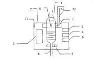
图1为本实用新型基于机器视觉的医疗输液速度监测与控制装置的结构示意图;Fig. 1 is the structural representation of the medical infusion speed monitoring and control device based on machine vision of the present invention;
图2为本实用新型装置配合输液滴管使用的示意图;Fig. 2 is the schematic diagram that the device of the present invention cooperates with the infusion dropper to use;
图3为本实用新型实施例所使用的图像采集装置的结构示意图;Fig. 3 is a schematic structural view of the image acquisition device used in the embodiment of the present invention;
图4为本实用新型实施例所使用的滴速控制装置的结构示意图;Fig. 4 is the structural representation of the drip speed control device that the utility model embodiment uses;
图5为本实用新型实施例的工作流程图。Fig. 5 is the working flowchart of the utility model embodiment.
具体实施方式Detailed ways
如图1和图2所示,本实用新型基于机器视觉的医疗输液速度监测与控制装置包括图像采集装置1、参数输入装置2、数据处理器3、数据显示装置4、滴速控制装置5、报警提示装置6、以及用于将上述装置与数据处理器集成在一起的壳体7。As shown in Figures 1 and 2, the medical infusion speed monitoring and control device based on machine vision of the present invention includes an
参数输入装置2、数据显示装置4和报警提示装置6安装在壳体7上。壳体7上设置有通孔,用于输液管8从中穿过。图像采集装置1、数据处理器3和滴速控制装置5固定在壳体7内部,图像采集装置1位于输液管的滴筒的一侧,滴速控制装置5位于滴筒下方。The
图像采集装置1用于采集输液管8的滴筒内滴液82的图像数据,将采集的图像数据传输给数据处理器3中的图像处理模块31。The
参数输入装置2用于接收用户的输入,并将接收的信息分别传送给数据处理器3中的数据显示模块32和数据分析模块33。其中,用户输入的参数包括用户期望的药液滴速(期望滴速),还可以包括其他用户感兴趣的信息。参数输入装置2可以是键盘或按键输入电路或其他能接收用户输入信息的设备,该装置通过数据线与数据处理器3相连。The
数据处理器3用于接收图像采集装置1传送来的图像数据信息以及参数输入装置2传送来的数据信息(期望滴速),并对图像数据信息进行处理计算出药液的实时滴速,通过对这两个滴速进行分析,产生相应的数据显示信息、滴速控制信息以及报警提示信息,并将这些控制信息分别传送给数据显示装置4、滴速控制装置5以及报警提示装置6。The
数据处理器3包括图像处理模块31、数据显示模块32、数据分析模块33、报警提示模块34以及滴速控制模块35,该数据处理器3可以是微控制器芯片或DSP处理器或其它能够运行上述各模块的数据处理设备。其中,图像处理模块31用于接收图像采集装置1传送来的图像数据,根据接收到的图像数据计算药液的实时滴速,并将计算的实时滴速信息传送给数据显示模块32和数据分析模块33,其中,计算药液的实时滴速的方法如下:首先,根据图像处理的方法检测出运动的滴液,可用到的检测的方法有:帧间差法、背景差法以及光流法等,然后,对检测到的当前滴液和前一滴滴液之间的时间间隔进行记录,最后,根据记录的时间间隔计算出当前滴液的实时滴速。
数据显示模块32用于接收参数输入装置2和图像处理模块31传送来的数据,并将其传输给数据显示装置4,同时向数据显示装置4传送要求将其显示给用户的控制指令。The data display module 32 is used to receive the data transmitted by the
数据分析模块33用于接收参数输入装置2传送来的数据(期望滴速)和图像处理模块31传送来的数据(实测滴速),并对两者进行比较和分析,得出两者之间的大小关系的信息,并将该信息传送给滴速控制模块35,同时将实测滴速与某些事先设定的参数进行比较,得出实测滴速与这些参数的大小关系的信息,并将该信息传送给报警提示模块34,其中,事先设定的参数可代表如下意义:医护人员期望的滴速、药液快滴完了的滴速、出现针头脱出的滴速、出现针头堵塞的滴速或其他可能对病人身体造成伤害或造成医疗事故的一些滴速值。The data analysis module 33 is used to receive the data (expected dripping speed) that the
报警提示模块34用于接收数据分析模块33传送来的实测滴速与某些事先设定的参数的大小关系的信息,并根据该信息产生相应的报警提示的控制指令,将该控制指令发送给报警提示装置6,如:若接收到数据分析模块33传送来的信息为实测滴速大于医护人员期望的滴速,则向报警提示装置6发送要求以蜂鸣声来进行报警提示的控制指令,其中,蜂鸣声代表的信息为实测滴速超过了医护人员期望的滴速。The alarm prompting module 34 is used for receiving the information of the measured drop speed and the size relationship of some preset parameters transmitted by the data analysis module 33, and generates corresponding alarm prompting control instructions according to the information, and sends the control instructions to
滴速控制模块35用于接收数据分析模块33传送来的实测滴速与期望滴速的大小关系的信息,并根据该信息产生是否要求改变滴速的控制指令,并将控制指令传送给滴速控制装置5,若要求改变滴速,则将实测滴速与期望滴速差的绝对值也传送给滴速控制装置5。产生控制指令的方法可以优选如下方式:若接收到的是实测滴速比期望滴速小的信息,则产生要求使滴速增快的控制指令,若接收到的是实测滴速比期望滴速大的信息,则产生要求使滴速减慢的控制指令,若接收到的是实测滴速与期望滴速相等的信息,则产生不必改变滴速的控制指令。The drop speed control module 35 is used to receive the information of the measured drop speed and the expected drop speed sent by the data analysis module 33, and generate a control instruction whether to require changing the drop speed according to the information, and send the control instruction to the drop speed. If the
数据显示装置4用于接收数据显示模块32传送来的控制指令以及数据信息等,并按照控制指令将接收到的数据信息等显示给用户。数据显示装置4可以是LED数码管或液晶显示屏或其他能显示数据的设备,该装置通过数据线与数据处理器3相连。The
滴速控制装置5与数据处理器3通过驱动电路相连,滴速控制装置5用于接收滴速控制模块35传送来的控制指令以及实测滴速与期望滴速差的绝对值等数据信息,并按照该指令以及数据信息来控制电机的动作,最终实现对滴速进行调整,达到使实测滴速和期望滴速相同或接近的目的。The drop
报警提示装置6用于接收报警提示模块34传送来的控制指令,并按照该控制指令产生相应的报警提示信息。The
报警提示装置6采用可以发声/可以发光/可以产生电信号,或其他能直接/间接引起人们注意力的设备,其中,发声的设备可以是蜂鸣器,也可以是扬声器等;发光设备可以是LED灯,也可以是普通灯等;可以产生电信号的设备可以是无线电发射装置,这种电信号可以被安装在护士室的无线电接收装置接收,并以一定的形式提醒值班的护士,该报警提示装置6通过数据线与数据处理器3相连。The
下面再分别举例对图像采集装置1、以及滴速控制装置5的具体构成作更详细的描述。The specific configurations of the
如图3所示,图像采集装置1包括摄像头11、采集罩12、采集罩背板13以及光源14。采集罩背板13与采集罩12分别位于输液管的两侧的位置。摄像头11固定于采集罩12内,用于摄取感兴趣滴管内图像数据并将数据通过数据线传输到数据处理器3中的图像处理模块31中;采集罩12用于固定摄像头11,在摄像头采集输液滴筒内的图像数据时,采集罩保持摄像头到滴筒的距离不变;采集罩背板13涂成单色(涂成黑色效果会更好),使摄像头采集的有用的信息内容不受或少受背景的干扰,提高采集内容的有用性。光源14安装在采集罩12的一侧,用于调节摄像头11拍摄画面的亮度,以保证拍摄图像的清晰度,根据具体情况也可以不使用光源。As shown in FIG. 3 , the
如图4所示,滴速控制装置5包括电机51、连轴器52、滚珠丝杠53、丝杠螺母54、调速棒55以及滴管固定架56。滴管固定架56用于固定滴管81,使得滴管81受调速棒55的挤压时不会发生倾斜。电机51和滚珠丝杠53通过连轴器52相连,丝杠螺母54固定在滚珠丝杠53上,丝杠螺母54和调速棒55相连。电机51运动时,通过连轴器52带动滚珠丝杠53旋转,滚珠丝杠53的旋转又带动丝杠螺母54向左/右运动,丝杠螺母54向左/右运动促使调速棒55相应地向左/右移动,达到使药液滴速减小/增大的目的。As shown in FIG. 4 , the dripping
在使用该装置时,首先将本装置通过壳体7上方的固定支架72固定在输液支架合适的位置上,同时将输液管8也固定在输液支架上,医护人员设置初始滴速为极小值,并开始给病人输液,同时,启动本装置,通过参数输入装置2输入期望滴速值,装置即可开始对输液过程中的输液滴速进行自动计算、显示,同时,还能对输液滴速进行精确控制/调整,此外,装置在监测到可能有危险情况发生时,可以自动报警。When using the device, first fix the device at a suitable position on the infusion stand through the fixing
实施例:Example:
下面对本实用新型的实施作进一步具体的说明,本实用新型适用于具有莫非氏滴管的普通输液医疗器具。该实施例中,使用该装置对一个患有心脏病的儿童进行输液治疗,用户的要求包括:期望输液滴速为20滴/分钟,同时,在输液的过程中可以利用该装置对输液滴速进行检测,若实际测量到的输液滴速与期望的滴速(20滴/分钟)不同时,该装置可以自动对滴速进行调整,以和期望的滴速(20滴/分钟)达到相同或接近。此外,用户认为在输液过程中滴速为4-20滴/分钟为正常状态,则,若在输液过程中,出现下表表1中所列情况之一时,该装置可以通过发出不同的声音来向用户进行报警提示,其中,每种声音类型代表了不同的意义(不同的报警内容):The implementation of the present utility model is described in further detail below. The utility model is suitable for common transfusion medical appliances with Murphy's dropper. In this embodiment, the device is used to perform infusion therapy on a child suffering from heart disease. The user's requirements include: the desired infusion drip rate is 20 drops/minute, and at the same time, the device can be used to adjust the infusion drip rate during the infusion process. For detection, if the actually measured infusion drip rate is different from the expected drip rate (20 drops/min), the device can automatically adjust the drip rate to be the same as the expected drip rate (20 drops/min) or near. In addition, the user thinks that the drip rate of 4-20 drops/min is normal during the infusion process, then, if one of the situations listed in the following table 1 occurs during the infusion process, the device can emit different sounds. Alert the user, where each sound type represents a different meaning (different alarm content):
表1各种不同的需要进行报警提示的情况Table 1 Various situations that require alarm prompts
如图3所示,利用塑料加工采集罩12和采集罩背板13,采集罩背板13与采集罩12分别位于输液管8的两侧的位置,摄像头11和光源14固定在采集罩12的内部,可调焦镜头从采集罩12的圆孔露出朝向输液滴筒,光源14采用白色光源,可根据需要放置在采集罩12内部的合适的位置。摄像头11连有数据线,数据线的另一端与图像处理器3相连接。采集罩背板13正对着输液滴筒的一面涂成黑色。As shown in Fig. 3, utilize plastic
如图4所示,利用塑料加工滴管固定架56,使得输液管8下端的滴管81受调速棒55的挤压时不会发生倾斜。电机51和滚珠丝杠53通过连轴器52相连,丝杠螺母54固定在滚珠丝杠53上,丝杠螺母54和调速棒55相连。电机51运动时,通过连轴器52带动滚珠丝杠53旋转,滚珠丝杠53的旋转又带动丝杠螺母54向左/右运动,丝杠螺母54向左/右运动促使调速棒55相应地向左/右移动,从而增加/减小对输液管壁的压力,以此进行输液流量/滴速的控制。电机51通过驱动电路与数据处理器3相连。本实施例中,步进电机51顺时针/逆时针旋转1圈代表使调速棒55向左/右移动1厘米,相应地,滴速1分钟内减小/增大1滴。As shown in FIG. 4 , the
如图5所示,输液速度监测与控制装置的工作流程为:As shown in Figure 5, the workflow of the infusion speed monitoring and control device is as follows:
(1)输液设备以及本装置的安装以及初始化设置。将本装置通过固定支架72固定在输液支架的合适位置,输液管8也固定在输液支架上,同时,设置初始滴速为极小值。(1) Installation and initialization of infusion equipment and this device. This device is fixed on the suitable position of infusion support by fixing
(2)医护人员通过参数输入装置2输入药液的期望滴速20滴/分钟,并将该期望滴速传送给数据显示模块32和数据分析模块33;(2) The medical personnel input the expected dripping speed of 20 drops/min of the medicinal liquid through the
(3)摄取滴筒内的图像。利用摄像头12对滴筒内的图像进行实时拍摄,将拍摄的实时图像数据传输给图像处理模块31;(3) Capture the image inside the dropper. Utilize
(4)利用图像处理的方法计算药液的实时滴速。计算滴速的具体步骤和方法如下:(4) Calculate the real-time dripping speed of the liquid medicine by means of image processing. The specific steps and methods for calculating the drop rate are as follows:
(4.1)图像预处理。预处理包括:对每帧图像进行对比度增强以及降噪等一系列处理,处理的方法可用一般的对比度增强以及降噪的图像处理方法;(4.1) Image preprocessing. Preprocessing includes: performing a series of processing such as contrast enhancement and noise reduction on each frame image, and the processing method can be a general contrast enhancement and noise reduction image processing method;
(4.2)提取背景图像。使用帧间差分以及二值帧差掩膜的方法得到标准(稳定不变)的背景图像;(4.2) Extract the background image. Use the method of inter-frame difference and binary frame difference mask to obtain a standard (stable) background image;
(4.3)分割出运动的滴液。所用到的方法为背景消减法,即用当前帧图像减去步骤(4.2)提取的背景图像;(4.3) Segment the moving droplets. The method used is the background subtraction method, that is, the background image extracted in step (4.2) is subtracted from the current frame image;
(4.4)计算实时滴速。根据记录得到用上述方法检测到当前滴液和前一滴滴液之间的时间间隔为12秒(0.2分钟),则计算出滴液的实时滴速(实测滴速)为5滴/分钟。(4.4) Calculate the real-time drop rate. According to the record, it is 12 seconds (0.2 minutes) to detect that the time interval between the current drop and the previous drop is 12 seconds (0.2 minutes), and then the real-time drip speed (actually measured drip speed) of the drip is calculated to be 5 drops/minute.
(5)显示实时滴速和期望滴速等信息。数据显示模块32接收步骤2和步骤(4.4)分别传送来的期望滴速20滴/分钟和实测滴速5滴/分钟后,将这两个数据以及要求显示这两个数据的控制指令传送给数据显示装置4,数据显示装置4将这两个数据显示给用户。(5) Display information such as real-time dripping speed and expected dripping speed. After the data display module 32 receives
(6)分析期望滴速和实测滴速,产生并发送控制指令(包括报警提示指令和滴速控制指令)和数据信息。具体步骤和方法如下:(6) Analyze the expected dripping speed and the measured dripping speed, generate and send control instructions (including alarm prompt instructions and drip speed control instructions) and data information. The specific steps and methods are as follows:
(6.1)数据分析模块33接收步骤2和步骤(4.4)分别传送来的期望滴速20滴/分钟和实测滴速5滴/分钟;(6.1) The data analysis module 33 receives
(6.2)分析实测滴速5滴/分钟与几个事先设定的参数(0、4滴/分钟、20滴/分钟、40滴/分钟)的大小关系,发现5滴/分钟在输液的正常状态(20-40滴/分钟)范围之内,则产生并向报警提示装置6发送不要求产生报警提示的控制指令。(6.2) Analyzing the relationship between the measured drop rate of 5 drops/min and several pre-set parameters (0, 4 drops/min, 20 drops/min, 40 drops/min), it was found that 5 drops/min was in the normal range of infusion. Within the scope of state (20-40 drop/minute), then generate and send to the
(6.3)经分析发现实测滴速5滴/分钟小于期望滴速20滴/分钟后,产生要求增大滴速的控制指令,并将该指令以及实测滴速5滴/分钟与期望滴速20滴/分钟差的绝对值15发送给滴速控制装置5。(6.3) After analysis, it is found that the measured dripping speed of 5 drops/min is less than the expected dripping speed of 20 drops/min, a control command for increasing the dripping speed is generated, and the command and the measured dripping speed of 5 drops/min are compared with the expected dripping speed of 20 drops/min. The absolute value 15 of the drop/minute difference is sent to the drip
(7)产生报警提示信息,调整药液滴速。报警提示装置执行步骤(6.2)产生的指令,不向用户发出报警提示信息;滴速控制装置5执行步骤(6.3)产生的指令,驱动电机51逆时针旋转一定的圈数(如:15圈,),电机51的运动最终使得调速棒向右运动15厘米,减小了调速棒55对滴管81的挤压,从而达到使1分钟内通过滴管81的流量增大15滴左右的目的。(7) Generate an alarm prompt message and adjust the dripping speed of the medicinal liquid. The command that alarm prompting device executes step (6.2) produces does not send alarm prompt information to the user; Drop
(8)若医护人员想改变期望滴速,则重复上述步骤(2)-(7),否则,重复上述步骤(3)-(7)。(8) If the medical personnel want to change the desired drip rate, then repeat the above steps (2)-(7), otherwise, repeat the above steps (3)-(7).
在约1小时后,步骤(4)计算出药液的实时滴速为0,此后,步骤(6)分析得到这一实时滴速0不在正常滴速4-20滴/分钟的范围之内,得出可能是药液快滴完了的结论,则报警提示装置以蜂鸣声产生报警提示信息,以引起医护人员的注意,提醒医护人员此位病人需要拔针了或需要换药液了。After about 1 hour, step (4) calculates that the real-time drop speed of medicinal liquid is 0, after this, step (6) analyzes and obtains that this real-time drop speed 0 is not within the scope of normal drop speed 4-20 drop/min, Draw the conclusion that may be that the medicinal liquid is almost dripped, then the alarm prompting device generates an alarm prompt message with a buzzing sound to attract the attention of the medical staff, and remind the medical staff that the patient needs to pull out the needle or needs to change the drug solution.
Claims (3)
Translated fromChinesePriority Applications (1)
| Application Number | Priority Date | Filing Date | Title |
|---|---|---|---|
| CNU2007200888329UCN201110955Y (en) | 2007-12-07 | 2007-12-07 | A medical infusion speed monitoring and control device based on machine vision |
Applications Claiming Priority (1)
| Application Number | Priority Date | Filing Date | Title |
|---|---|---|---|
| CNU2007200888329UCN201110955Y (en) | 2007-12-07 | 2007-12-07 | A medical infusion speed monitoring and control device based on machine vision |
Publications (1)
| Publication Number | Publication Date |
|---|---|
| CN201110955Ytrue CN201110955Y (en) | 2008-09-03 |
Family
ID=39895493
Family Applications (1)
| Application Number | Title | Priority Date | Filing Date |
|---|---|---|---|
| CNU2007200888329UExpired - Fee RelatedCN201110955Y (en) | 2007-12-07 | 2007-12-07 | A medical infusion speed monitoring and control device based on machine vision |
Country Status (1)
| Country | Link |
|---|---|
| CN (1) | CN201110955Y (en) |
Cited By (26)
| Publication number | Priority date | Publication date | Assignee | Title |
|---|---|---|---|---|
| WO2012006896A1 (en)* | 2010-07-15 | 2012-01-19 | Kaitao Kai | Iv monitoring by video and image processing |
| WO2012104779A1 (en)* | 2011-02-02 | 2012-08-09 | Kai Tao Kai | Image processing, frequency estimation, mechanical control and illumination for an automatic iv monitoring and controlling system |
| CN105188805A (en)* | 2013-03-13 | 2015-12-23 | 康尔福盛303公司 | Infusion order and delivery consistency |
| US9741001B2 (en) | 2000-05-18 | 2017-08-22 | Carefusion 303, Inc. | Predictive medication safety |
| CN107106768A (en)* | 2015-01-13 | 2017-08-29 | 株式会社村田制作所 | Dropping amount measuring device, dropping amount controller, dripping device, and liquid droplet volume measuring device |
| CN107320806A (en)* | 2011-12-21 | 2017-11-07 | 德卡产品有限公司 | device for controlling fluid flow |
| US9981085B2 (en) | 2005-02-11 | 2018-05-29 | Carefusion, 303, Inc. | Management of pending medication orders |
| US10029047B2 (en) | 2013-03-13 | 2018-07-24 | Carefusion 303, Inc. | Patient-specific medication management system |
| US10062457B2 (en) | 2012-07-26 | 2018-08-28 | Carefusion 303, Inc. | Predictive notifications for adverse patient events |
| US10064579B2 (en) | 2004-08-25 | 2018-09-04 | Carefusion 303, Inc. | System and method for dynamically adjusting patient therapy |
| US10275571B2 (en) | 2000-05-18 | 2019-04-30 | Carefusion 303, Inc. | Distributed remote asset and medication management drug delivery system |
| US10353856B2 (en) | 2011-03-17 | 2019-07-16 | Carefusion 303, Inc. | Scalable communication system |
| US10430554B2 (en) | 2013-05-23 | 2019-10-01 | Carefusion 303, Inc. | Medication preparation queue |
| US10867265B2 (en) | 2013-03-13 | 2020-12-15 | Carefusion 303, Inc. | Predictive medication safety |
| US11087873B2 (en) | 2000-05-18 | 2021-08-10 | Carefusion 303, Inc. | Context-aware healthcare notification system |
| US11182728B2 (en) | 2013-01-30 | 2021-11-23 | Carefusion 303, Inc. | Medication workflow management |
| US11339887B2 (en) | 2011-12-21 | 2022-05-24 | Deka Products Limited Partnership | Flow meter and related method |
| USD964563S1 (en) | 2019-07-26 | 2022-09-20 | Deka Products Limited Partnership | Medical flow clamp |
| US11449037B2 (en) | 2011-12-21 | 2022-09-20 | Deka Products Limited Partnership | System, method, and apparatus for monitoring, regulating, or controlling fluid flow |
| CN115429972A (en)* | 2022-10-06 | 2022-12-06 | 陈明宇 | Device and method based on intelligent clinical infusion tree |
| USD972125S1 (en) | 2016-05-25 | 2022-12-06 | Deka Products Limited Partnership | Apparatus to control fluid flow through a tube |
| US11738143B2 (en) | 2011-12-21 | 2023-08-29 | Deka Products Limited Partnership | Flow meier having a valve |
| US11744935B2 (en) | 2016-01-28 | 2023-09-05 | Deka Products Limited Partnership | Apparatus for monitoring, regulating, or controlling fluid flow |
| CN117323499A (en)* | 2023-10-19 | 2024-01-02 | 浙江大学 | An infusion speed alarm and its infusion speed monitoring and alarm system |
| US12079742B2 (en) | 2013-05-22 | 2024-09-03 | Carefusion 303, Inc. | Medication workflow management |
| US12100507B2 (en) | 2011-12-21 | 2024-09-24 | Deka Products Limited Partnership | System, method, and apparatus for monitoring, regulating, or controlling fluid flow |
- 2007
- 2007-12-07CNCNU2007200888329Upatent/CN201110955Y/ennot_activeExpired - Fee Related
Cited By (45)
| Publication number | Priority date | Publication date | Assignee | Title |
|---|---|---|---|---|
| US10275571B2 (en) | 2000-05-18 | 2019-04-30 | Carefusion 303, Inc. | Distributed remote asset and medication management drug delivery system |
| US11823791B2 (en) | 2000-05-18 | 2023-11-21 | Carefusion 303, Inc. | Context-aware healthcare notification system |
| US9741001B2 (en) | 2000-05-18 | 2017-08-22 | Carefusion 303, Inc. | Predictive medication safety |
| US11087873B2 (en) | 2000-05-18 | 2021-08-10 | Carefusion 303, Inc. | Context-aware healthcare notification system |
| US10064579B2 (en) | 2004-08-25 | 2018-09-04 | Carefusion 303, Inc. | System and method for dynamically adjusting patient therapy |
| US11590281B2 (en) | 2005-02-11 | 2023-02-28 | Carefusion 303, Inc. | Management of pending medication orders |
| US9981085B2 (en) | 2005-02-11 | 2018-05-29 | Carefusion, 303, Inc. | Management of pending medication orders |
| US10668211B2 (en) | 2005-02-11 | 2020-06-02 | Carefusion 303, Inc. | Management of pending medication orders |
| CN103179995A (en)* | 2010-07-15 | 2013-06-26 | 陶锴 | Iv monitoring by video and image processing |
| US8531517B2 (en) | 2010-07-15 | 2013-09-10 | Kai Tao | IV monitoring by video and image processing |
| WO2012006896A1 (en)* | 2010-07-15 | 2012-01-19 | Kaitao Kai | Iv monitoring by video and image processing |
| WO2012104779A1 (en)* | 2011-02-02 | 2012-08-09 | Kai Tao Kai | Image processing, frequency estimation, mechanical control and illumination for an automatic iv monitoring and controlling system |
| US11734222B2 (en) | 2011-03-17 | 2023-08-22 | Carefusion 303, Inc. | Scalable communication system |
| US10353856B2 (en) | 2011-03-17 | 2019-07-16 | Carefusion 303, Inc. | Scalable communication system |
| US11366781B2 (en) | 2011-03-17 | 2022-06-21 | Carefusion 303, Inc. | Scalable communication system |
| US10983946B2 (en) | 2011-03-17 | 2021-04-20 | Carefusion 303, Inc. | Scalable communication system |
| CN111658892A (en)* | 2011-12-21 | 2020-09-15 | 德卡产品有限公司 | Device for controlling fluid flow |
| US11574407B2 (en) | 2011-12-21 | 2023-02-07 | Deka Products Limited Partnership | System, method, and apparatus for monitoring, regulating, or controlling fluid flow |
| US11793928B2 (en) | 2011-12-21 | 2023-10-24 | Deka Products Limited Partnership | Flow meter and related method |
| CN107320806B (en)* | 2011-12-21 | 2021-06-15 | 德卡产品有限公司 | device for controlling fluid flow |
| US11738143B2 (en) | 2011-12-21 | 2023-08-29 | Deka Products Limited Partnership | Flow meier having a valve |
| US11339887B2 (en) | 2011-12-21 | 2022-05-24 | Deka Products Limited Partnership | Flow meter and related method |
| US12100507B2 (en) | 2011-12-21 | 2024-09-24 | Deka Products Limited Partnership | System, method, and apparatus for monitoring, regulating, or controlling fluid flow |
| CN107320806A (en)* | 2011-12-21 | 2017-11-07 | 德卡产品有限公司 | device for controlling fluid flow |
| US11449037B2 (en) | 2011-12-21 | 2022-09-20 | Deka Products Limited Partnership | System, method, and apparatus for monitoring, regulating, or controlling fluid flow |
| US10062457B2 (en) | 2012-07-26 | 2018-08-28 | Carefusion 303, Inc. | Predictive notifications for adverse patient events |
| US11182728B2 (en) | 2013-01-30 | 2021-11-23 | Carefusion 303, Inc. | Medication workflow management |
| CN105188805A (en)* | 2013-03-13 | 2015-12-23 | 康尔福盛303公司 | Infusion order and delivery consistency |
| US10937530B2 (en) | 2013-03-13 | 2021-03-02 | Carefusion 303, Inc. | Patient-specific medication management system |
| US12001981B2 (en) | 2013-03-13 | 2024-06-04 | Carefusion 303, Inc. | Predictive medication safety |
| US10867265B2 (en) | 2013-03-13 | 2020-12-15 | Carefusion 303, Inc. | Predictive medication safety |
| US10029047B2 (en) | 2013-03-13 | 2018-07-24 | Carefusion 303, Inc. | Patient-specific medication management system |
| US11615871B2 (en) | 2013-03-13 | 2023-03-28 | Carefusion 303, Inc. | Patient-specific medication management system |
| US12079742B2 (en) | 2013-05-22 | 2024-09-03 | Carefusion 303, Inc. | Medication workflow management |
| US10430554B2 (en) | 2013-05-23 | 2019-10-01 | Carefusion 303, Inc. | Medication preparation queue |
| CN107106768A (en)* | 2015-01-13 | 2017-08-29 | 株式会社村田制作所 | Dropping amount measuring device, dropping amount controller, dripping device, and liquid droplet volume measuring device |
| US11744935B2 (en) | 2016-01-28 | 2023-09-05 | Deka Products Limited Partnership | Apparatus for monitoring, regulating, or controlling fluid flow |
| USD972125S1 (en) | 2016-05-25 | 2022-12-06 | Deka Products Limited Partnership | Apparatus to control fluid flow through a tube |
| USD972718S1 (en) | 2016-05-25 | 2022-12-13 | Deka Products Limited Partnership | Apparatus to control fluid flow through a tube |
| USD1060608S1 (en) | 2016-05-25 | 2025-02-04 | Deka Products Limited Partnership | Device to control fluid flow through a tube |
| USD964563S1 (en) | 2019-07-26 | 2022-09-20 | Deka Products Limited Partnership | Medical flow clamp |
| CN115429972A (en)* | 2022-10-06 | 2022-12-06 | 陈明宇 | Device and method based on intelligent clinical infusion tree |
| CN115429972B (en)* | 2022-10-06 | 2024-05-24 | 陈明宇 | Device and method based on intelligent clinical infusion tree |
| CN117323499A (en)* | 2023-10-19 | 2024-01-02 | 浙江大学 | An infusion speed alarm and its infusion speed monitoring and alarm system |
| CN117323499B (en)* | 2023-10-19 | 2025-01-10 | 浙江大学 | Infusion speed alarm and infusion speed monitoring alarm system thereof |
Similar Documents
| Publication | Publication Date | Title |
|---|---|---|
| CN201110955Y (en) | A medical infusion speed monitoring and control device based on machine vision | |
| CN100535811C (en) | System for monitoring and controlling medical transfusion speed based on machine vision | |
| CN106362234B (en) | Venous transfusion manages device and venous transfusion manages system | |
| US20170173260A1 (en) | Infusion system and method for controlling the flow rate of liquid medicine thereof | |
| US9067016B2 (en) | Infusion monitoring device and method for monitoring the infusion dripping rate and alarming for the irregularities of the infusion | |
| CN201154122Y (en) | Infra-red ray infusion monitoring apparatus | |
| EP2902050A1 (en) | Intelligent infusion pump | |
| CN202682470U (en) | Novel intelligent transfusion device | |
| CN202516103U (en) | Liquid dropping speed measurement monitoring device | |
| CN109200393A (en) | A kind of interactive mode transfusion monitoring system and monitoring method | |
| CN107349487B (en) | A kind of intravenous infusion monitoring equipment and alarm system | |
| CN109303944A (en) | A kind of transfusion system | |
| CN113144327A (en) | Medical intelligent auxiliary infusion device and infusion method based on machine vision | |
| CN205814775U (en) | A kind of automatic transfusion device | |
| CN108283741A (en) | A kind of SCM Based Intelligent drip nursing system | |
| CN215690609U (en) | Controllable infusion alarm of velocity of flow | |
| CN215460838U (en) | A medical intelligent auxiliary infusion device based on machine vision | |
| CN212997789U (en) | Infusion process state monitoring device | |
| CN206239826U (en) | Liquid dripping speed monitoring device | |
| CN204637151U (en) | A kind of transfusion system | |
| CN111686346A (en) | Infusion process state monitoring device and monitoring method | |
| CN208877510U (en) | An intravenous infusion monitoring device | |
| CN114681711B (en) | Intelligent infusion system for vasoactive drugs | |
| CN215231079U (en) | A regulator for controlling the number of intravenous drips | |
| CN212439596U (en) | Intelligent infusion device and intelligent infusion equipment |
Legal Events
| Date | Code | Title | Description |
|---|---|---|---|
| C14 | Grant of patent or utility model | ||
| GR01 | Patent grant | ||
| C17 | Cessation of patent right | ||
| CF01 | Termination of patent right due to non-payment of annual fee | Granted publication date:20080903 Termination date:20101207 |