CN201101488Y - Three-section separable wireless dust collector - Google Patents
Three-section separable wireless dust collectorDownload PDFInfo
- Publication number
- CN201101488Y CN201101488YCNU2007201772480UCN200720177248UCN201101488YCN 201101488 YCN201101488 YCN 201101488YCN U2007201772480 UCNU2007201772480 UCN U2007201772480UCN 200720177248 UCN200720177248 UCN 200720177248UCN 201101488 YCN201101488 YCN 201101488Y
- Authority
- CN
- China
- Prior art keywords
- vacuum cleaner
- seat
- slot
- cleaner body
- pivot
- Prior art date
- Legal status (The legal status is an assumption and is not a legal conclusion. Google has not performed a legal analysis and makes no representation as to the accuracy of the status listed.)
- Expired - Fee Related
Links
- 239000000428dustSubstances0.000titleclaimsabstractdescription69
- 238000003780insertionMethods0.000claimsdescription15
- 230000037431insertionEffects0.000claimsdescription15
- 230000005540biological transmissionEffects0.000claimsdescription9
- 230000002093peripheral effectEffects0.000claimsdescription9
- OJIJEKBXJYRIBZ-UHFFFAOYSA-Ncadmium nickelChemical compound[Ni].[Cd]OJIJEKBXJYRIBZ-UHFFFAOYSA-N0.000claimsdescription3
- 229910052739hydrogenInorganic materials0.000claimsdescription2
- 239000001257hydrogenSubstances0.000claimsdescription2
- 210000001061foreheadAnatomy0.000claims1
- 238000004806packaging method and processMethods0.000abstractdescription6
- 238000004140cleaningMethods0.000abstractdescription2
- 238000012423maintenanceMethods0.000abstractdescription2
- 230000000694effectsEffects0.000description5
- 241001417534LutjanidaeSpecies0.000description3
- 238000003825pressingMethods0.000description2
- 238000010276constructionMethods0.000description1
- 238000010586diagramMethods0.000description1
- 230000007774longtermEffects0.000description1
- 229910052987metal hydrideInorganic materials0.000description1
- 238000000034methodMethods0.000description1
Images


Landscapes
- Filters For Electric Vacuum Cleaners (AREA)
Abstract
Description
Translated fromChinese技术领域technical field
本实用新型涉及一种三段可分离式无线吸尘器,可方便的拆卸与组装,其拆卸后的体积小,可便于包装、运输或储放,且具有可直接更换充电电池以及操作灵活方便的优点。The utility model relates to a three-section detachable wireless vacuum cleaner, which can be disassembled and assembled conveniently. After disassembly, the volume is small, which is convenient for packaging, transportation or storage, and has the advantages of direct replacement of rechargeable batteries and flexible and convenient operation. .
背景技术Background technique
习用的无线吸尘器9(即无电源线的充电式吸尘器)请配合参考图1所示,由于吸尘器本体91与吸盘92不能拆卸,因此无论包装、运输或储放都相当占用空间与材积,其次,前述的无线吸尘器在使用操作时也不够灵活,虽然有些业者提供了吸尘器本体可单独拆卸的无线吸尘器,但当吸尘器本体拆卸之后仍然存在长度、宽度与体积很大的壳体以及充电基座,进而仍具有体积大不利于包装、运输或储存的缺点;次查此种无线吸尘器的吸尘器本体与吸盘之间虽可活动,但其吸盘底部所枢设的可被马达传动的地刷必须要连接吸尘器本体内部的电力来源,因此需通过电源导线来连接,如此一来,吸尘器本体与吸盘之间的导线直接暴露将会影响美观性,若以软管等挠性体包覆不但增加施工组配的人力与工时,也容易影响操作转动的灵活性,再者,当电力用完时必须将整个吸尘器本体置设于一充电基座进行长时间的充电作业,因此家庭主妇等使用者的打扫作业必须停止.等到充电完毕才能继续,因而造成使用者的困扰与不便。Please refer to FIG. 1 for the conventional cordless vacuum cleaner 9 (that is, a rechargeable vacuum cleaner without a power cord). Since the
新型内容new content
有鉴于前述习用无线吸尘器的诸多缺点,本设计人经过不断的研究与改进,终于创作设计出一种三段可分离式无线吸尘器。In view of the many shortcomings of the aforementioned conventional wireless vacuum cleaners, the designer finally created and designed a three-stage detachable wireless vacuum cleaner through continuous research and improvement.
因此,本实用新型的主要目的在于提供一种三段可分离式无线吸尘器,具有拆卸容易、组配方便,且拆卸之后可节省材积而便于包装、运输与储存作业,且具有可直接更换充电电池以及操作灵活方便的优点。Therefore, the main purpose of this utility model is to provide a three-stage detachable cordless vacuum cleaner, which is easy to disassemble and assemble, and after disassembly can save volume and facilitate packaging, transportation and storage operations, and has the ability to directly replace the rechargeable battery And the advantages of flexible and convenient operation.
为了达到上述目的,本实用新型的技术方案如下:In order to achieve the above object, the technical scheme of the utility model is as follows:
一种三段可分离式无线吸尘器,其中该吸尘器本体分别设有马达扇叶装置与集尘座,该集尘座内并设有滤网杯与集尘内杯;A three-stage detachable cordless vacuum cleaner, wherein the vacuum cleaner body is respectively provided with a motor blade device and a dust collection seat, and a filter cup and a dust collection inner cup are provided in the dust collection seat;
其特征在于:It is characterized by:
该三段可分离式无线吸尘器在吸尘器本体的上方插接一握把,而该吸尘器本体的下方则插接吸盘,其中:The three-section detachable cordless vacuum cleaner has a handle inserted above the vacuum cleaner body, and a suction cup is inserted below the vacuum cleaner body, wherein:
该握把下方具有插接部可插套入吸尘器本体的上方,该握把的接近于插接部的部位另设有一弹性卡笋,使该弹性卡笋的按键部凸出于握把所另设的槽孔,而该弹性卡笋的卡扣则凸出于插接部的槽孔;The bottom of the handle has an insertion part that can be inserted into the upper part of the vacuum cleaner body, and the part of the handle close to the insertion part is additionally provided with an elastic latch, so that the button part of the elastic latch protrudes from the other part of the handle. The slot hole provided, and the buckle of the elastic buckle protrudes from the slot hole of the insertion part;
该吸尘器本体上端设有连接槽以及位于连接槽内的卡槽,该连接槽可供握把的插接部插入,并使握把所设的弹性卡笋的卡扣卡入该连接槽内的卡槽内,使握把可与吸尘器本体上方插接并卡扣定位,而该吸尘器本体并形成一缺槽,该缺槽的上方形成一定位凸缘,该定位凸缘的中间为一开口,该开口恰位于马达扇叶装置的下方以形成一吸风口,该缺槽的下方内侧并具有一卡槽,通过该缺槽上方的定位凸缘可供一集尘座的上方的定位凹缘套入,再由该集尘座下方所设的弹性卡笋的卡扣卡入该缺槽下方的卡槽,而使集尘座可组接于吸尘器本体,且恰使集尘座的入风口面对该前述缺槽相邻的壁面的上方所设的入风口,该入风口并与吸尘器本体所设管路的上方连接,而该管路的下方则衔接该吸尘器本体的底部所设衔接槽,再者,该吸尘器本体的底部设有衔接槽以及位于该衔接槽内的两插孔,该两插孔的内侧并分别与吸尘器本体的内部所设的正、负极导电端子连接,且该正、负极导电端子的另一侧则分别连接导线,该吸尘器本体上方并进一步设有一开放槽孔以供固设一座壳,该座壳并具有一插槽,该插槽内并另设有与吸尘器本体内部相连通的两槽孔,该座壳的内部并分别由锁固组件锁固正、负极端子,并使该正、负极端子的一侧经由该相连通的两槽孔分别伸入于该插槽内,通过该插槽可供镍镉电池、镍氢电池等充电电池对应插接,并使充电电池的正、负极接触端可分别与前述座壳所设正极端子的一侧以及负极端子的一侧接触,而该正极端子的另一侧与负极端子的另一侧并分别与导线;The upper end of the vacuum cleaner body is provided with a connection groove and a card groove located in the connection groove. The connection groove can be inserted into the insertion part of the handle, and the buckle of the elastic buckle provided on the handle is snapped into the connection groove. In the card slot, the handle can be plugged with the top of the vacuum cleaner body and snapped into position, and the vacuum cleaner body also forms a slot, and a positioning flange is formed above the slot, and the middle of the positioning flange is an opening. The opening is located just below the motor blade device to form an air suction port, and the lower inner side of the slot has a card slot, and the positioning flange above the slot can be used for a positioning concave flange cover on the top of the dust collecting seat. Then, the buckle of the elastic snap shoot set under the dust collection seat is snapped into the slot under the slot, so that the dust collection seat can be assembled with the vacuum cleaner body, and the air inlet surface of the dust collection seat The air inlet provided above the wall adjacent to the aforementioned slot, the air inlet is connected to the upper part of the pipeline provided on the vacuum cleaner body, and the lower part of the pipeline is connected to the connecting groove provided on the bottom of the vacuum cleaner body, Moreover, the bottom of the vacuum cleaner body is provided with a connecting groove and two sockets located in the connecting groove, and the inner sides of the two sockets are respectively connected to the positive and negative conductive terminals provided inside the vacuum cleaner body, and the positive and negative electrodes are connected to each other. The other side of the negative conductive terminal is respectively connected to the wires. An open slot is further provided on the top of the vacuum cleaner body for fixing a housing. The housing also has a slot. The inside of the housing is connected with two slots, and the positive and negative terminals are respectively locked by locking components inside the seat shell, and one side of the positive and negative terminals is respectively extended into the socket via the two connected slots. In the slot, rechargeable batteries such as nickel-cadmium batteries and nickel-metal hydride batteries can be plugged in through the slot, and the positive and negative contact ends of the rechargeable battery can be connected to the side of the positive terminal and the negative terminal of the aforementioned seat shell respectively. one side of which is in contact with the other side of the positive terminal and the other side of the negative terminal and respectively with the wire;
该吸盘,其壳体与底盘各具有弧形槽,进而当壳体与底盘锁固连结之后可通过前述弧形槽与一轴座的枢轴枢接,使该轴座呈可前后活动状态,而该轴座的上方并具有轴管可供枢套入一枢接座的下方,使枢接座呈可旋转状态,该轴座并可进一步设有两挡部,而枢接座的下方则另设一限位块以限制枢接座的旋转角度,该枢接座另设有两嵌卡部可分别卡设正极导电销与负极导电销,而该正、负极导电销的另一侧则分别与导线的一侧连接,该枢接座的前侧另由锁固组件连结一前盖,并使该枢接座卡设的正、负极导电销的上方向上伸出该前盖的上端,该前盖的下方并具有一定位块,当前述轴座向前活动使枢接座的前盖的定位块位于吸盘的壳体所设的定位槽内时可阻挡枢接座,相对使轴座呈不能向前活动的状态,且使枢接座不能大幅度的旋转而达到定位的效果,而当枢接座连同轴座枢转而使定位块脱离前述壳体的定位槽时,该枢接座恢复可旋转状态,而轴座也呈可前后活动状态,该前述的枢接座的上方并具有插接部可供插设入吸尘器本体下方的衔接槽,并使其卡设定位的正、负极导电销的上方可分别插入位于该衔接槽内的两插孔内,且使该正、负极导电销的上方可分别与前述两插孔内的正、负极导电端子接触,进而使吸尘器本体内部的电力可经由吸尘器本体内部的导线、正、负极导电端子以及吸盘的枢接座所设正、负极导电销、吸盘内部的导线传导给吸盘内所设的马达。The suction cup has an arc-shaped groove on its casing and chassis, and then when the casing and the chassis are locked and connected, it can be pivotally connected to the pivot of a shaft seat through the aforementioned arc-shaped groove, so that the shaft seat can move forward and backward. And the top of the shaft seat has a shaft tube that can be pivotally inserted into the bottom of a pivot seat, so that the pivot seat is in a rotatable state. The shaft seat can be further provided with two stoppers, and the bottom of the pivot seat is In addition, a limit block is provided to limit the rotation angle of the pivot joint seat, and the pivot joint seat is provided with two engaging parts, which can respectively clamp the positive electrode conductive pin and the negative electrode conductive pin, and the other side of the positive and negative electrode conductive pins is They are respectively connected to one side of the wires, and the front side of the pivot seat is connected to a front cover by a locking component, and the upper end of the front cover protrudes upward from the upper end of the positive and negative conductive pins clamped by the pivot seat. There is a positioning block under the front cover. When the aforementioned shaft seat moves forward, the positioning block of the front cover of the pivot seat can be blocked when the positioning block of the front cover of the pivot seat is located in the positioning groove provided by the shell of the suction cup. The seat is in a state of being unable to move forward, and the pivot seat cannot be rotated greatly to achieve the positioning effect, and when the pivot seat pivots together with the shaft seat to make the positioning block break away from the positioning groove of the aforementioned housing, the The pivotal seat returns to the rotatable state, and the shaft seat is also in a forward and backward movable state. The aforementioned pivotal seat has a plug-in part on the top that can be inserted into the connecting groove under the vacuum cleaner body, and makes it snap into place. The top of the positive and negative conductive pins can be respectively inserted into the two jacks located in the connecting groove, and the top of the positive and negative conductive pins can be respectively in contact with the positive and negative conductive terminals in the aforementioned two jacks, so that The power inside the vacuum cleaner body can be conducted to the motor provided in the suction cup through the wires inside the vacuum cleaner body, the positive and negative conductive terminals, the positive and negative conductive pins on the pivot seat of the suction cup, and the wires inside the suction cup.
所述的三段可分离式无线吸尘器,其中该握把所设弹性卡笋的内侧并抵套一弹簧,而弹簧的内侧则抵接于握把的内部的壁面,当弹性卡笋的按键部被向内按压时即压缩着弹簧,并连同弹性卡笋另一侧的卡扣向内缩,当停止按压该按键部时则可连同另一侧的卡扣归复原位。In the three-stage detachable cordless vacuum cleaner, the inner side of the elastic clamp provided on the handle is abutted against a spring, and the inner side of the spring is in contact with the inner wall of the handle, when the button part of the elastic clamp When pressed inwardly, the spring is compressed, and retracts inward together with the buckle on the other side of the elastic buckle, and returns to the original position together with the buckle on the other side when the pressing of the key part is stopped.
所述的三段可分离式无线吸尘器,其中该吸尘器本体所设座壳的插槽进一步设有一与吸尘器本体内部连通的槽孔,该槽孔并可供座壳进一步枢设的弹性卡笋的一侧所设卡扣伸入,进而当前述充电电池插入该插槽时,该卡扣恰可嵌卡入充电电池的一侧的卡槽内以防止充电电池脱离,而该弹性卡笋的另一侧具有按键部,该按键部的外侧略伸出于吸尘器本体另配合设置的槽孔,而该按键部的内侧抵接一弹簧,该弹簧的另一侧则抵接座壳的相面对的内壁的适当部位,当弹性卡笋的按键部被向内按压时可压缩弹簧并使该弹性卡笋枢转,而使另一侧的卡扣脱离充电电池的卡槽,进而可使充电电池被取出而脱离该座壳的插槽,另外,前述弹性卡笋通过枢轴与座壳内部另设的枢接座枢接。The three-stage detachable cordless vacuum cleaner, wherein the slot of the seat shell provided on the vacuum cleaner body is further provided with a slot connected with the inside of the vacuum cleaner body, and the slot hole can also be used for the seat shell to be further pivoted. The buckle provided on one side extends in, and when the aforementioned rechargeable battery is inserted into the slot, the buckle can be inserted into the slot on one side of the rechargeable battery to prevent the rechargeable battery from detaching, while the other side of the elastic buckle One side has a button part, and the outer side of the button part slightly protrudes from the slot hole provided in the vacuum cleaner body, and the inner side of the button part abuts a spring, and the other side of the spring abuts against the facing surface of the seat shell The appropriate part of the inner wall of the elastic buckle can compress the spring and pivot the elastic buckle when the button part of the elastic buckle is pressed inward, so that the buckle on the other side is out of the slot of the rechargeable battery, and then the rechargeable battery can be released. In addition, the above-mentioned elastic snap shoots are pivotally connected with the pivot joint seat provided inside the seat shell through the pivot shaft.
所述的三段可分离式无线吸尘器,其中该吸盘内部所设的马达的轴心套设一齿轮,并由该齿轮与传动皮带的一侧啮合,而传动皮带的另一侧则与底盘所枢设的地刷的轴心的一侧所设齿轮啮合,进而当马达转动时可带动传动皮带,使传动皮带的另一侧啮合的齿轮可带动地刷的轴心转动。In the three-stage detachable cordless vacuum cleaner, a gear is sheathed on the shaft center of the motor provided inside the suction cup, and the gear is meshed with one side of the transmission belt, while the other side of the transmission belt is connected with the chassis. The gears on one side of the axis of the pivoted ground brush are engaged, and then when the motor rotates, the transmission belt can be driven, so that the gears engaged on the other side of the transmission belt can drive the axis of the ground brush to rotate.
所述的三段可分离式无线吸尘器,其中该吸尘器本体的衔接槽内进一步设有一卡槽,而前述吸盘所设的枢接座可进一步设有枢接槽,而该枢接座连结的前盖也进一步设有一槽孔可供一弹性卡笋的外侧的按键部套入,而该弹性卡笋的上方则具有卡扣,且弹性卡笋的下方则具有枢轴部可供枢设于前述枢接座的枢槽,该前述按键部的内侧并抵套一弹簧,进而当前盖与枢接座连结固定之后,该弹性卡笋的卡扣向上伸出前盖,而当前述枢接座通过其插接部插设入吸尘器本体的衔接槽时,该弹性卡笋的卡扣恰可卡扣入位于衔接槽内的卡槽内,而使吸盘可与吸尘器本体进一步的卡扣定位,而当弹性卡笋的按键部被向内按压时即相对使另一侧的卡扣枢转而脱离卡槽,进而可直接将吸盘的枢接座的插接部与吸尘器本体的衔接槽分离。In the aforementioned three-stage detachable cordless vacuum cleaner, a card slot is further provided in the connecting groove of the vacuum cleaner body, and the pivot joint seat provided on the aforementioned suction cup can further be provided with a pivot joint slot, and the front joint connected by the pivot joint seat The cover is also further provided with a slot for the outer button portion of an elastic snapper to be inserted, and the top of the elastic snapper has a buckle, and the bottom of the elastic snapper has a pivot portion for pivoting on the aforementioned The pivot groove of the pivot seat, the inner side of the aforementioned button part is set against a spring, and after the front cover and the pivot seat are connected and fixed, the buckle of the elastic buckle protrudes upwards from the front cover, and when the aforementioned pivot seat passes through its When the plug-in part is inserted into the connecting groove of the vacuum cleaner body, the buckle of the elastic buckle can be snapped into the locking groove located in the connecting groove, so that the suction cup can be further buckled and positioned with the vacuum cleaner body, and when the elastic When the button part of the buckle is pressed inward, the buckle on the other side is relatively pivoted away from the slot, and then the insertion part of the pivot seat of the suction cup can be directly separated from the connecting groove of the vacuum cleaner body.
所述的三段可分离式无线吸尘器,其中该集尘座进一步由锁固组件连结一底盖,该底盖具有枢槽以枢接弹性卡笋的枢轴,并使弹性卡笋的按键部与另一侧的卡扣分别伸出底盖两侧的槽孔,该按键部的内侧并抵套一弹簧,当底盖与集尘座的底面锁固连结时,该弹簧的另一侧抵接于集尘座的底面,进而当按键部被按压时即相对可使其另一侧的卡扣枢转而向下位移。In the three-stage detachable cordless vacuum cleaner, the dust collecting seat is further connected to a bottom cover by a locking component, and the bottom cover has a pivot groove to pivotally connect the pivot of the elastic latch, and make the button part of the elastic latch The buckles on the other side extend out of the slots on both sides of the bottom cover respectively, and the inner side of the button part is set against a spring. It is connected to the bottom surface of the dust collecting seat, and then when the key part is pressed, it can pivot and move downward relative to the buckle on the other side.
所述的三段可分离式无线吸尘器,其中该集尘座的上方进一步设有内定位端缘以供一滤网杯的上方外周端缘抵靠,而使该滤网杯装设于集尘座内部上方,且该滤网杯的上方并具有内周端缘可供一集尘内杯的上方外周缘端抵靠,使集尘内杯可置入滤网杯的上方,当集尘内杯置入滤网杯而连同滤网杯置入于集尘座的上方时即可将集尘座组接于前述吸尘器本体。In the three-stage detachable wireless vacuum cleaner, an inner positioning edge is further provided on the top of the dust collection seat for the upper peripheral edge of a filter cup to abut against, so that the filter cup is installed on the dust collection Above the inside of the seat, and the top of the filter cup has an inner peripheral edge for the upper outer peripheral edge of a dust-collecting inner cup to lean against, so that the dust-collecting inner cup can be placed above the filter cup, when the dust-collecting inner cup is placed When the filter cup is placed on the top of the dust collection seat together with the filter cup, the dust collection seat can be assembled to the aforementioned vacuum cleaner body.
所述的三段可分离式无线吸尘器,其中该吸尘器本体可进一步设有一凹槽并连结一把手以便于使用者握持施力。In the three-section detachable cordless vacuum cleaner, the vacuum cleaner body can be further provided with a groove and connected with a handle so that the user can hold and apply force.
本实用新型一种三段可分离式无线吸尘器,其吸盘所设的枢接座设有正、负极导电销,当枢接座与吸尘器本体的衔接槽插接时,该正、负极导电销可分别与吸尘器本体的正、负极导电端子接触以连接该吸尘器本体内的电力来源,并同时可达到吸盘与吸尘器本体组接对准方便、操作灵活的效果;在其吸尘器本体上方设置座壳以供直接插接充电电池,而当充电电池的电力耗尽时只要更换新的充电电池即可继续使用。The utility model is a three-section detachable wireless vacuum cleaner. The pivot joint seat provided by the suction cup is provided with positive and negative conductive pins. Contact the positive and negative conductive terminals of the vacuum cleaner body respectively to connect the power source in the vacuum cleaner body, and at the same time achieve the effect of convenient alignment and flexible operation of the suction cup and the vacuum cleaner body; a seat shell is provided above the vacuum cleaner body for The rechargeable battery is directly plugged in, and when the power of the rechargeable battery is exhausted, it can continue to be used as long as a new rechargeable battery is replaced.
附图说明Description of drawings
兹配合附图详加说明如后。Hereby cooperate accompanying drawing to explain in detail as following.
图1:为习用无线吸尘器的立体图;Figure 1: A perspective view of a conventional cordless vacuum cleaner;
图2:为本实用新型实施例的立体分解图;Fig. 2: is the three-dimensional exploded view of the utility model embodiment;
图3:为本实用新型实施例的立体图;Fig. 3: is the perspective view of the utility model embodiment;
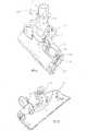
图4:为本实用新型实施例的另一角度立体分解图;Fig. 4: It is another three-dimensional exploded view of the utility model embodiment;
图5:为本实用新型实施例其中握把与吸尘器本体的部份组合断面图;Fig. 5: A sectional view of part of the combination of the handle and the vacuum cleaner body in the embodiment of the present utility model;
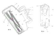
图6:为本实用新型实施例其中吸尘器本体所设集尘座拆离后的立体图;Fig. 6: It is a three-dimensional view after the dust collecting seat of the vacuum cleaner body is detached in the embodiment of the present utility model;
图7:为本实用新型实施例其中吸尘器本体所设集尘座拆离后的另一角度立体图;Fig. 7: It is another perspective view after the dust collecting seat of the vacuum cleaner body is detached in the embodiment of the present utility model;
图8:为本实用新型实施例其中吸尘器本体连同吸盘所设轴座向后活动且枢转一角度后的部份立体示意图;Figure 8 is a partial perspective view of the vacuum cleaner body and the shaft seat on the suction cup moving backward and pivoting at an angle in the embodiment of the present utility model;
图9:为本实用新型实施例其中吸尘器本体的底视部份立体放大图;Fig. 9 is a three-dimensional enlarged view of the bottom view of the vacuum cleaner body in the embodiment of the present invention;
图10:为本实用新型实施例其中吸盘的部份构件分解状态立体放大图;Figure 10: It is a three-dimensional enlarged view of the disassembled state of some components of the suction cup in the embodiment of the present invention;
图11:为本实用新型实施例其中吸盘的壳体拆卸后的立体放大图;Figure 11: It is a three-dimensional enlarged view after the housing of the suction cup is disassembled in the embodiment of the present invention;
图12:为本实用新型实施例其中吸盘的壳体的另一角度立体放大图;Figure 12: It is another perspective enlarged view of the housing of the suction cup in the embodiment of the present invention;
图13:为本实用新型实施例其中吸尘器本体的部份组合断面图;Fig. 13 is a partly combined sectional view of the vacuum cleaner body in the embodiment of the present invention;
图14:为本实用新型实施例其中吸尘器本体的充电电池的部份立体分解图;Figure 14: Partial perspective exploded view of the rechargeable battery of the vacuum cleaner body in the embodiment of the present invention;
图15:为本实用新型实施例其中吸尘器本体的充电电池的另一角度立体图;Figure 15: Another perspective view of the rechargeable battery of the vacuum cleaner body in the embodiment of the present invention;
图16:为本实用新型实施例其中吸尘器本体的部份立体断面示意图;Fig. 16: is a partial three-dimensional cross-sectional view of the vacuum cleaner body in the embodiment of the present utility model;
图17:为本实用新型实施例其中吸尘器本体的另一角度部份组合断面图;Fig. 17: It is a combined sectional view of another angle part of the vacuum cleaner body in the embodiment of the present utility model;
图18:为本实用新型实施例其中吸盘的底视立体放大图;Fig. 18: It is a bottom perspective enlarged view of the suction cup in the embodiment of the utility model;
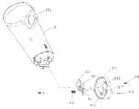
图19:为本实用新型实施例其中集尘座与滤网杯以及集尘内杯的立体组合放大图;Figure 19: An enlarged view of the three-dimensional combination of the dust collection seat, the filter cup and the dust collection inner cup in the embodiment of the utility model;
图20:为本实用新型实施例其中集尘座与滤网杯以及集尘内杯的部份立体分解放大图;Figure 20: Partial exploded three-dimensional exploded view of the dust collection seat, the filter cup and the dust collection inner cup in the embodiment of the present utility model;
图21:为本实用新型实施例其中集尘座的部份构件立体分解放大图;Figure 21: It is a three-dimensional exploded and enlarged view of some components of the dust collection seat in the embodiment of the present utility model;
图22:为本实用新型实施例其中集尘座的部份组合断面放大图;Figure 22: An enlarged view of a part of the combined section of the dust collection seat in the embodiment of the present invention;
图23:为本实用新型实施例其中吸尘器本体单独使用且装设吸嘴与刷具的立体示意图。Fig. 23 is a three-dimensional schematic diagram of the embodiment of the utility model in which the vacuum cleaner body is used alone and is equipped with a suction nozzle and a brush.
具体实施方式Detailed ways
如图2~图23所示,本实用新型一种三段可分离式无线吸尘器,包括有:As shown in Figures 2 to 23, the utility model is a three-stage detachable wireless vacuum cleaner, including:
一握把10,下方具有插接部101可插套入吸尘器本体1的上方,该握把10的接近于插接部101的部位另设有一弹性卡笋15,使该弹性卡笋15的按键部151凸出于握把10所另设的槽孔102,而该弹性卡笋15的卡扣152则凸出于插接部101的槽孔1011(参考图5),该弹性卡笋15的内侧并抵套一弹簧16(参考图5),而弹簧16的内侧则抵接于握把10的内部的壁面108,当弹性卡笋15的按键部151被向内按压时即压缩着弹簧16,并连同弹性卡笋15另一侧的卡扣152向内缩,当停止按压该按键部151时则可连同另一侧的卡扣152归复原位;A
一吸尘器本体1,上端设有连接槽17以及位于连接槽17内的卡槽171(参考图5),该连接槽17可供握把10的插接部101插入,并使握把10所设的弹性卡笋15的卡扣152卡入该连接槽17内的卡槽171内,使握把10可与吸尘器本体1上方插接并卡扣定位,该吸尘器本体1的上方内部并设有习知的马达扇叶装置100(另参考图16),而该吸尘器本体1并形成一缺槽18(另参考图6),该缺槽18的上方形成一定位凸缘181,该定位凸缘181的中间为一开口1811,该开口1811恰位于马达扇叶装置100的下方以形成一吸风口,该缺槽18的下方内侧并具有一卡槽182,通过该缺槽18上方的定位凸缘181可供一集尘座19的上方的定位凹缘191(另参考图20)套入,再由该集尘座19下方所设的弹性卡笋14的卡扣142(参考图19)卡入该缺槽18下方的卡槽182,而使集尘座19可组接于吸尘器本体1,且恰使集尘座19的入风口192面对该前述缺槽18相邻的壁面的上方所设的入风口183(参考图6),该入风口183并与吸尘器本体1所设管路105(参考图7)的上方1051连接,而该管路105的下方1052则衔接该吸尘器本体1的底部所设衔接槽11,又当欲拆离前述集尘座19时,只要按压弹性卡笋14的按键部141即可使其卡扣142向下而脱离吸尘器本体1的缺槽18下方内侧的卡槽182(参考图6),随即可方便的拆离集尘座19;再者,该吸尘器本体1的底部设有衔接槽11(参考图9)以及位于该衔接槽11内的两插孔111、112,该两插孔111、112的内侧并分别与吸尘器本体1的内部所设的正、负极导电端子71、72(参考图13)连接,且该正、负极导电端子71、72的另一侧则分别连接导线61、62,通过该导线61、62可供与吸尘器本体1的内部的电力来源连接,该吸尘器本体1上方并进一步设有一开放槽孔12以供固设一座壳13,该座壳13并具有一插槽131,该插槽131内并另设有与吸尘器本体1内部相连通的两槽孔1311、1312,该座壳13的内部(参考图16)并分别由锁固组件(例如螺丝)123、124锁固正、负极端子132、133,并使该正、负极端子132、133的一侧经由该相连通的两槽孔1311、1312分别伸入于该插槽131内,通过该插槽131可供镍镉电池、镍氢电池等充电电池134对应插接,并使充电电池134的正、负极接触端1341、1342(另参考图15)可分别与前述座壳13所设正极端子132的一侧1321以及负极端子133的一侧1331接触,而该正极端子132的另一侧与负极端子133的另一侧(参考图16)并分别与导线1351、1352、1352’连接以提供电力给吸尘器本体1内部的马达风扇组100等其它部位;另参考图17所示,前述的吸尘器本体1所设座壳13的插槽131进一步设有一与吸尘器本体1内部连通的槽孔1313,该槽孔1313并可供座壳13进一步枢设的弹性卡笋137的一侧所设卡扣1371伸入(参考图17),进而当前述充电电池134插入该插槽131时,该卡扣1371恰可嵌卡入充电电池134的一侧的卡槽1343内以防止充电电池134脱离,而该弹性卡笋137的另一侧具有按键部1372,该按键部1372的外侧略伸出于吸尘器本体1另配合设置的槽孔122,而该按键部1372的内侧抵接一弹簧1373(参考图17),该弹簧1373的另一侧则抵接座壳13的相面对的内壁138的适当部位,当弹性卡笋137的按键部1372被向内按压时可压缩弹簧1373并使该弹性卡笋137枢转,而使另一侧的卡扣1371脱离充电电池134的卡槽1343,进而可使充电电池134被取出而脱离该座壳13的插槽131,另者,前述弹性卡笋137由枢轴1374与座壳13内部另设的枢接座130枢接(参考图16);A
一吸盘2,其壳体21与底盘22各具有弧形槽211、221(参考图11、图12),进而当壳体21与底盘22锁固连结之后可通过前述弧形槽211、221与一轴座3的枢轴31枢接(参考图11),使该轴座3呈可前后活动状态,而该轴座3的上方并具有轴管34(参考图10)可供枢套入一枢接座4的下方,使枢接座4呈可旋转状态,该轴座3并可进一步设有两挡部32、33,而枢接座4的下方则另设一限位块41(参考图10)以限制枢接座4的旋转角度,该枢接座4另设有两嵌卡部42、43可分别卡设正极导电销51与负极导电销52,而该正、负极导电销51、52的另一侧则分别与导线81、82的一侧连接,而该两导线81、82则可与底盘22内所设的马达20(参考图11)或线路装置(图未示)连接,该枢接座4的前侧另由锁固组件49(参考图10)连结一前盖44(参考图11),并使该枢接座4卡设的正、负极导电销51、52的上方向上伸出该前盖44的上端,该前盖44的下方并具有一定位块441,当前述轴座3向前活动使枢接座4的前盖44的定位块441位于吸盘2的壳体21所设的定位槽212内时可阻挡枢接座4,相对使轴座3呈不能向前活动的状态,且使枢接座4不能大幅度的旋转而达到定位的效果,而当枢接座4连同轴座3枢转而使定位块441脱离前述壳体21的定位槽212时,该枢接座4恢复可旋转状态(参考图8),而轴座3也呈可前后活动状态,该前述的枢接座4的上方并具有插接部40可供插设入吸尘器本体1下方的衔接槽11,并使其卡设定位的正、负极导电销51、52的上方可分别插入位于该衔接槽11内的两插孔111、112内,且使该正、负极导电销51、52的上方可分别与前述两插孔111、112内的正、负极导电端子71、72接触,进而使吸尘器本体1内部的电力可经由吸尘器本体1内部的导线61、62(参考图13)、正、负极导电端子71、72以及吸盘2的枢接座4所设正、负极导电销51、52、吸盘2内部的导线81、82传导给吸盘2内所设的马达20或线路装置甚至吸盘2内的其它需要电力的部位使用,本实施例的马达20(参考图11)的轴心为套设一齿轮201,并由该齿轮201与传动皮带202的一侧啮合,而传动皮带202的另一侧则与底盘22所枢设的地刷24的轴心241的一侧所设齿轮203啮合,进而当马达20转动时可带动传动皮带202,使传动皮带202的另一侧啮合的齿轮203可带动地刷24(参考图18)的轴心241转动。A suction cup 2, its housing 21 and chassis 22 each have arc grooves 211, 221 (refer to Fig. 11, Fig. 12), and then when the housing 21 and chassis 22 are locked and connected, they can pass through the aforementioned arc grooves 211, 221 and The pivot 31 of an axle seat 3 is pivotally connected (referring to FIG. 11 ), so that the axle seat 3 can move back and forth, and the top of the axle seat 3 has a shaft tube 34 (referring to FIG. 10 ) which can be pivoted into a Below the pivotal seat 4, the pivotal seat 4 is in a rotatable state, and the shaft seat 3 can be further provided with two stoppers 32, 33, and a limit block 41 is further provided under the pivotal seat 4 (refer to Fig. 10) to limit the rotation angle of the pivotal seat 4, the pivotal seat 4 is additionally provided with two engaging parts 42, 43 which can respectively clamp the positive electrode conductive pin 51 and the negative electrode conductive pin 52, and the positive and negative electrode conductive pins 51 The other side of , 52 is connected with one side of wire 81, 82 respectively, and these two wires 81, 82 then can be connected with the motor 20 (referring to Fig. 11) or wiring device (not shown) that is set in the chassis 22 , the front side of the pivotal seat 4 is also connected to a front cover 44 (refer to FIG. 11 ) by a locking assembly 49 (refer to FIG. 10 ), and the positive and negative conductive pins 51, 52 of the pivotal seat 4 are clamped. The upper end of the
再者,前述的吸尘器本体1的衔接槽11内进一步设有一卡槽113(参考图9),而前述吸盘2所设的枢接座4可进一步设有枢接槽48,而该枢接座4连结的前盖44也进一步设有一槽孔442可供一弹性卡笋45的外侧的按键部451套入,而该弹性卡笋45的上方则具有卡扣452,且弹性卡笋45的下方则具有枢轴部453(参考图10)可供枢设于前述枢接座4的枢槽48,该前述按键部451的内侧并抵套一弹簧46,进而当前盖44与枢接座4连结固定之后,该弹性卡笋45的卡扣452向上伸出前盖44,而当前述枢接座4由其插接部40插设入吸尘器本体1的衔接槽111时,该弹性卡笋45的卡扣452恰可卡扣入位于衔接槽11内的卡槽113内,而使吸盘2可与吸尘器本体1进一步的卡扣定位,而当弹性卡笋45的按键部451被向内按压时即相对使另一侧的卡扣452枢转而脱离卡槽113,进而可直接将吸盘2的枢接座4的插接部40与吸尘器本体1的衔接槽11分离。Moreover, the above-mentioned
另者,配合参考图19~图22所示,前述集尘座19进一步由锁固组件198(参考图21)连结一底盖193,该底盖193具有枢槽1931以枢接弹性卡笋14的枢轴143,并使弹性卡笋14的按键部141与另一侧的卡扣142分别伸出底盖193两侧的槽孔1932、1933,该按键部141的内侧并抵套一弹簧140,当底盖193与集尘座19的底面锁固连结时,该弹簧140的另一侧抵接于集尘座19的底面,进而当按键部14被按压时即相对可使其另一侧的卡扣142枢转而向下位移。In addition, as shown in FIGS. 19 to 22 , the aforementioned
又,参考图20所示,前述集尘座19的上方进一步设有内定位端缘195以供一滤网杯196的上方外周端缘1961抵靠,而使该滤网杯196装设于集尘座19内部上方,且该滤网杯196的上方并具有内周端缘1962可供一集尘内杯197的上方外周缘端1971抵靠,使集尘内杯197可置入滤网杯196的上方,当集尘内杯197置入滤网杯196而连同滤网杯196置入于集尘座19的上方时即可将集尘座19组接于前述吸尘器本体1。Also, as shown in Figure 20, the top of the aforementioned
另外,前述吸尘器本体1可进一步设有一凹槽103并连结一把手104以便于使用者握持施力。In addition, the aforementioned vacuum
综上所述,本实用新型可归纳具有下列增进功效:In summary, the utility model can be summed up to have the following enhancement effects:
1.握把10、吸尘器本体1与吸盘2可三段式分离拆卸不占空间,便于包装、运输或储存作业,并具有组装容易、拆卸方便的目的1. The
2.吸盘2所设的枢接座4设有正、负极导电销51、52,当枢接座4与吸尘器本体1的衔接槽11插接时,该正、负极导电销51、52可分别与吸尘器本体1的正、负极导电端子71、72接触以连接该吸尘器本体1内的电力来源,并同时可达到吸盘2与吸尘器本体1组接对准操作方便的优点。2. The
3.当不使用时可经调整而使枢接座4的定位块441位于壳体21的定位槽212内而具有定位效果。3. When not in use, it can be adjusted so that the
4.吸盘2所枢设的轴座3呈可前后活动状态,而轴座3枢接的枢接座4呈可旋转状态,相对使枢接座4衔接吸尘器本体1具有灵活操作的方便性。4. The
5.吸尘器本体1上方设有一座壳13,该座壳13并具有一插槽131可直接插接充电电池134而提供电力给吸尘器本体1以进行吸尘的动作,而当充电电池134的电力耗尽时可直接更换新的充电电池134并继续进行吸尘动作,使用方便。5. There is a
6.集尘座19可方便的拆卸,而滤网杯196与集尘内杯197也可方便的取出以便于使用者清洁、保养。6. The
7.吸尘器本体1可与握把10以及吸盘2拆卸分离后单独使用,且可进一步装设小型吸嘴106(参考图23)并进一步装设刷具107来使用。7. The
8.吸尘器本体1的把手104相邻一凹槽103,因此手部的握持与施力操作更方便。8. The
Claims (8)
Translated fromChinesePriority Applications (1)
| Application Number | Priority Date | Filing Date | Title |
|---|---|---|---|
| CNU2007201772480UCN201101488Y (en) | 2007-10-30 | 2007-10-30 | Three-section separable wireless dust collector |
Applications Claiming Priority (1)
| Application Number | Priority Date | Filing Date | Title |
|---|---|---|---|
| CNU2007201772480UCN201101488Y (en) | 2007-10-30 | 2007-10-30 | Three-section separable wireless dust collector |
Publications (1)
| Publication Number | Publication Date |
|---|---|
| CN201101488Ytrue CN201101488Y (en) | 2008-08-20 |
Family
ID=39948505
Family Applications (1)
| Application Number | Title | Priority Date | Filing Date |
|---|---|---|---|
| CNU2007201772480UExpired - Fee RelatedCN201101488Y (en) | 2007-10-30 | 2007-10-30 | Three-section separable wireless dust collector |
Country Status (1)
| Country | Link |
|---|---|
| CN (1) | CN201101488Y (en) |
Cited By (45)
| Publication number | Priority date | Publication date | Assignee | Title |
|---|---|---|---|---|
| CN101816531A (en)* | 2009-02-03 | 2010-09-01 | 株式会社牧田 | Handy cleaners |
| US9015899B2 (en) | 2009-03-13 | 2015-04-28 | G.B.D. Corp. | Surface cleaning apparatus with different cleaning configurations |
| US9198551B2 (en) | 2013-02-28 | 2015-12-01 | Omachron Intellectual Property Inc. | Surface cleaning apparatus |
| US9226633B2 (en) | 2009-03-13 | 2016-01-05 | Omachron Intellectual Property Inc. | Surface cleaning apparatus |
| US9232877B2 (en) | 2010-03-12 | 2016-01-12 | Omachron Intellectual Property Inc. | Surface cleaning apparatus with enhanced operability |
| US9301662B2 (en) | 2006-12-12 | 2016-04-05 | Omachron Intellectual Property Inc. | Upright vacuum cleaner |
| US9314138B2 (en) | 2013-02-28 | 2016-04-19 | Omachron Intellectual Property Inc. | Surface cleaning apparatus |
| CN105640437A (en)* | 2016-01-29 | 2016-06-08 | 苏州爱建电器有限公司 | Clamping-connecting type dust suction pipe of dust collector and handheld dust collector |
| US9364127B2 (en) | 2013-02-28 | 2016-06-14 | Omachron Intellectual Property Inc. | Surface cleaning apparatus |
| US9386895B2 (en) | 2009-03-13 | 2016-07-12 | Omachron Intellectual Property Inc. | Surface cleaning apparatus |
| US9392916B2 (en) | 2009-03-13 | 2016-07-19 | Omachron Intellectual Property Inc. | Surface cleaning apparatus |
| US9427122B2 (en) | 2009-03-13 | 2016-08-30 | Omachron Intellectual Property Inc. | Surface cleaning apparatus |
| US9451852B2 (en) | 2009-03-13 | 2016-09-27 | Omachron Intellectual Property Inc. | Surface cleaning apparatus with different cleaning configurations |
| US9456721B2 (en) | 2013-02-28 | 2016-10-04 | Omachron Intellectual Property Inc. | Surface cleaning apparatus |
| US9480373B2 (en) | 2009-03-13 | 2016-11-01 | Omachron Intellectual Property Inc. | Surface cleaning apparatus |
| US9591953B2 (en) | 2009-03-13 | 2017-03-14 | Omachron Intellectual Property Inc. | Surface cleaning apparatus |
| US9693666B2 (en) | 2011-03-04 | 2017-07-04 | Omachron Intellectual Property Inc. | Compact surface cleaning apparatus |
| US9962050B2 (en) | 2016-08-29 | 2018-05-08 | Omachron Intellectual Property Inc. | Surface cleaning apparatus |
| US10136780B2 (en) | 2016-08-29 | 2018-11-27 | Omachron Intellectual Property Inc. | Surface cleaning apparatus |
| US10136779B2 (en) | 2016-08-29 | 2018-11-27 | Omachron Intellectual Property Inc. | Surface cleaning apparatus |
| US10292550B2 (en) | 2016-08-29 | 2019-05-21 | Omachron Intellectual Property Inc. | Surface cleaning apparatus |
| US10299649B2 (en) | 2013-02-28 | 2019-05-28 | Omachron Intellectual Property Inc. | Surface cleaning apparatus |
| US10321794B2 (en) | 2016-08-29 | 2019-06-18 | Omachron Intellectual Property Inc. | Surface cleaning apparatus |
| CN110022744A (en)* | 2016-11-21 | 2019-07-16 | 三星电子株式会社 | Clearing apparatus |
| US10405711B2 (en) | 2016-08-29 | 2019-09-10 | Omachron Intellectual Property Inc. | Surface cleaning apparatus |
| US10413141B2 (en) | 2016-08-29 | 2019-09-17 | Omachron Intellectual Property Inc. | Surface cleaning apparatus |
| US10433686B2 (en) | 2007-08-29 | 2019-10-08 | Omachron Intellectual Property Inc. | Configuration of a surface cleaning apparatus |
| US10433689B2 (en) | 2016-08-29 | 2019-10-08 | Omachron Intellectual Property Inc. | Surface cleaning apparatus |
| US10441124B2 (en) | 2016-08-29 | 2019-10-15 | Omachron Intellectual Property Inc. | Surface cleaning apparatus |
| US10441125B2 (en) | 2016-08-29 | 2019-10-15 | Omachron Intellectual Property Inc. | Surface cleaning apparatus |
| US10548442B2 (en) | 2009-03-13 | 2020-02-04 | Omachron Intellectual Property Inc. | Portable surface cleaning apparatus |
| CN111166231A (en)* | 2018-11-13 | 2020-05-19 | 苏州宝时得电动工具有限公司 | Dust collector and wireless charging device for same |
| WO2020107246A1 (en)* | 2018-11-28 | 2020-06-04 | 苏州凯丽达电器有限公司 | Handheld suction cleaner assembly |
| US10729295B2 (en) | 2016-08-29 | 2020-08-04 | Omachron Intellectual Property Inc. | Surface cleaning apparatus |
| US10765277B2 (en) | 2006-12-12 | 2020-09-08 | Omachron Intellectual Property Inc. | Configuration of a surface cleaning apparatus |
| WO2021253683A1 (en)* | 2020-06-17 | 2021-12-23 | 天佑电器(苏州)有限公司 | Reciprocation assembly, floor brush assembly for cleaning device, and cleaning device |
| CN114532888A (en)* | 2020-11-24 | 2022-05-27 | 莱克电气股份有限公司 | Vacuum cleaner |
| US11478117B2 (en) | 2016-08-29 | 2022-10-25 | Omachron Intellectual Property Inc. | Surface cleaning apparatus |
| US11612288B2 (en) | 2009-03-13 | 2023-03-28 | Omachron Intellectual Property Inc. | Surface cleaning apparatus |
| US11690489B2 (en) | 2009-03-13 | 2023-07-04 | Omachron Intellectual Property Inc. | Surface cleaning apparatus with an external dirt chamber |
| CN116369779A (en)* | 2023-04-21 | 2023-07-04 | 深圳市倍思科技有限公司 | Vacuum cleaner |
| US11751733B2 (en) | 2007-08-29 | 2023-09-12 | Omachron Intellectual Property Inc. | Portable surface cleaning apparatus |
| US12048409B2 (en) | 2007-03-11 | 2024-07-30 | Omachron Intellectual Property Inc. | Portable surface cleaning apparatus |
| US12220099B2 (en) | 2006-12-12 | 2025-02-11 | Omachron Intellectual Property Inc. | Surface cleaning apparatus |
| US12251716B2 (en) | 2016-12-27 | 2025-03-18 | Omachron Intellectual Property Inc. | Surface cleaning apparatus |
- 2007
- 2007-10-30CNCNU2007201772480Upatent/CN201101488Y/ennot_activeExpired - Fee Related
Cited By (85)
| Publication number | Priority date | Publication date | Assignee | Title |
|---|---|---|---|---|
| US11076729B2 (en) | 2006-12-12 | 2021-08-03 | Omachron Intellectual Property Inc. | Upright vacuum cleaner |
| US10765277B2 (en) | 2006-12-12 | 2020-09-08 | Omachron Intellectual Property Inc. | Configuration of a surface cleaning apparatus |
| US10076217B2 (en) | 2006-12-12 | 2018-09-18 | Omachron Intellectual Property Inc. | Upright vacuum cleaner |
| US12256882B2 (en) | 2006-12-12 | 2025-03-25 | Omachron Intellectual Property Inc. | Upright vacuum cleaner |
| US12220099B2 (en) | 2006-12-12 | 2025-02-11 | Omachron Intellectual Property Inc. | Surface cleaning apparatus |
| US11700984B2 (en) | 2006-12-12 | 2023-07-18 | Omachron Intellectual Property Inc. | Configuration of a surface cleaning apparatus |
| US9301662B2 (en) | 2006-12-12 | 2016-04-05 | Omachron Intellectual Property Inc. | Upright vacuum cleaner |
| US12048409B2 (en) | 2007-03-11 | 2024-07-30 | Omachron Intellectual Property Inc. | Portable surface cleaning apparatus |
| US11751733B2 (en) | 2007-08-29 | 2023-09-12 | Omachron Intellectual Property Inc. | Portable surface cleaning apparatus |
| US10561286B2 (en) | 2007-08-29 | 2020-02-18 | Omachron Intellectual Property Inc. | Configuration of a surface cleaning apparatus |
| US10542856B2 (en) | 2007-08-29 | 2020-01-28 | Omachron Intellectual Property Inc. | Configuration of a surface cleaning apparatus |
| US10433686B2 (en) | 2007-08-29 | 2019-10-08 | Omachron Intellectual Property Inc. | Configuration of a surface cleaning apparatus |
| US12324557B2 (en) | 2007-08-29 | 2025-06-10 | Omachron Intellectual Property Inc. | Portable surface cleaning apparatus |
| CN101816531B (en)* | 2009-02-03 | 2013-07-17 | 株式会社牧田 | Handy cleaners |
| CN101816531A (en)* | 2009-02-03 | 2010-09-01 | 株式会社牧田 | Handy cleaners |
| US9907444B2 (en) | 2009-03-13 | 2018-03-06 | Omachron Intellectual Property Inc. | Surface cleaning apparatus with different cleaning configurations |
| US11771276B2 (en) | 2009-03-13 | 2023-10-03 | Omachron Intellectual Property Inc. | Surface cleaning apparatus |
| US9480373B2 (en) | 2009-03-13 | 2016-11-01 | Omachron Intellectual Property Inc. | Surface cleaning apparatus |
| US9591953B2 (en) | 2009-03-13 | 2017-03-14 | Omachron Intellectual Property Inc. | Surface cleaning apparatus |
| US11571096B2 (en) | 2009-03-13 | 2023-02-07 | Omachron Intellectual Property Inc. | Surface cleaning apparatus with different cleaning configurations |
| US11529031B2 (en) | 2009-03-13 | 2022-12-20 | Omachron Intellectual Property Inc. | Portable surface cleaning apparatus |
| US9801511B2 (en) | 2009-03-13 | 2017-10-31 | Omachron Intellectual Property Inc. | Surface cleaning apparatus with different cleaning configurations |
| US9451852B2 (en) | 2009-03-13 | 2016-09-27 | Omachron Intellectual Property Inc. | Surface cleaning apparatus with different cleaning configurations |
| US11622659B2 (en) | 2009-03-13 | 2023-04-11 | Omachron Intellectual Property Inc. | Portable surface cleaning apparatus |
| US9015899B2 (en) | 2009-03-13 | 2015-04-28 | G.B.D. Corp. | Surface cleaning apparatus with different cleaning configurations |
| US9066642B2 (en) | 2009-03-13 | 2015-06-30 | G.B.D. Corp. | Surface cleaning apparatus with different cleaning configurations |
| US9427122B2 (en) | 2009-03-13 | 2016-08-30 | Omachron Intellectual Property Inc. | Surface cleaning apparatus |
| US12251074B2 (en) | 2009-03-13 | 2025-03-18 | Omachron Intellectual Property Inc. | Surface cleaning apparatus with an external dirt chamber |
| US11690489B2 (en) | 2009-03-13 | 2023-07-04 | Omachron Intellectual Property Inc. | Surface cleaning apparatus with an external dirt chamber |
| US9226633B2 (en) | 2009-03-13 | 2016-01-05 | Omachron Intellectual Property Inc. | Surface cleaning apparatus |
| US11330944B2 (en) | 2009-03-13 | 2022-05-17 | Omachron Intellectual Property Inc. | Portable surface cleaning apparatus |
| US11950751B2 (en) | 2009-03-13 | 2024-04-09 | Omachron Intellectual Property Inc. | Surface cleaning apparatus with an external dirt chamber |
| US10327608B2 (en) | 2009-03-13 | 2019-06-25 | Omachron Intellectual Property Inc. | Surface cleaning apparatus with different cleaning configurations |
| US11896183B2 (en) | 2009-03-13 | 2024-02-13 | Omachron Intellectual Property Inc. | Surface cleaning apparatus with different cleaning configuration |
| US9301663B2 (en) | 2009-03-13 | 2016-04-05 | Omachron Intellectual Property Inc. | Surface cleaning apparatus with different cleaning configurations |
| US11744417B2 (en) | 2009-03-13 | 2023-09-05 | Omachron Intellectual Property Inc. | Surface cleaning apparatus with different cleaning configuration |
| US9392916B2 (en) | 2009-03-13 | 2016-07-19 | Omachron Intellectual Property Inc. | Surface cleaning apparatus |
| US11771277B2 (en) | 2009-03-13 | 2023-10-03 | Omachron Intellectual Property Inc. | Surface cleaning apparatus |
| US11612288B2 (en) | 2009-03-13 | 2023-03-28 | Omachron Intellectual Property Inc. | Surface cleaning apparatus |
| US11771278B2 (en) | 2009-03-13 | 2023-10-03 | Omachron Intellectual Property Inc. | Surface cleaning apparatus |
| US10512374B2 (en) | 2009-03-13 | 2019-12-24 | Omachron Intellectual Property Inc. | Surface cleaning apparatus with different cleaning configurations |
| US9386895B2 (en) | 2009-03-13 | 2016-07-12 | Omachron Intellectual Property Inc. | Surface cleaning apparatus |
| US10548442B2 (en) | 2009-03-13 | 2020-02-04 | Omachron Intellectual Property Inc. | Portable surface cleaning apparatus |
| US9668631B2 (en) | 2010-03-12 | 2017-06-06 | Omachron Intellectual Property Inc. | Surface cleaning apparatus with enhanced operability |
| US11771275B2 (en) | 2010-03-12 | 2023-10-03 | Omachron Intellectual Property Inc. | Surface cleaning apparatus with enhanced operability |
| US9232877B2 (en) | 2010-03-12 | 2016-01-12 | Omachron Intellectual Property Inc. | Surface cleaning apparatus with enhanced operability |
| US11839342B2 (en) | 2010-03-12 | 2023-12-12 | Omachron Intellectual Property Inc. | Surface cleaning apparatus with enhanced operability |
| US9693666B2 (en) | 2011-03-04 | 2017-07-04 | Omachron Intellectual Property Inc. | Compact surface cleaning apparatus |
| US10602894B2 (en) | 2011-03-04 | 2020-03-31 | Omachron Intellectual Property Inc. | Portable surface cleaning apparatus |
| US11612283B2 (en) | 2011-03-04 | 2023-03-28 | Omachron Intellectual Property Inc. | Surface cleaning apparatus |
| US10893783B2 (en) | 2013-02-28 | 2021-01-19 | Omachron Intellectual Property Inc. | Surface cleaning apparatus |
| US9364127B2 (en) | 2013-02-28 | 2016-06-14 | Omachron Intellectual Property Inc. | Surface cleaning apparatus |
| US11889968B2 (en) | 2013-02-28 | 2024-02-06 | Omachron Intellectual Property Inc. | Surface cleaning apparatus |
| US9314138B2 (en) | 2013-02-28 | 2016-04-19 | Omachron Intellectual Property Inc. | Surface cleaning apparatus |
| US11700985B2 (en) | 2013-02-28 | 2023-07-18 | Omachron Intellectual Property Inc. | Surface cleaning apparatus |
| US10299649B2 (en) | 2013-02-28 | 2019-05-28 | Omachron Intellectual Property Inc. | Surface cleaning apparatus |
| US9198551B2 (en) | 2013-02-28 | 2015-12-01 | Omachron Intellectual Property Inc. | Surface cleaning apparatus |
| US9931005B2 (en) | 2013-02-28 | 2018-04-03 | Omachron lntellectual Property Inc. | Surface cleaning apparatus |
| US9456721B2 (en) | 2013-02-28 | 2016-10-04 | Omachron Intellectual Property Inc. | Surface cleaning apparatus |
| US10638897B2 (en) | 2013-02-28 | 2020-05-05 | Omachron Intellectual Property Inc. | Surface cleaning apparatus |
| US10624511B2 (en) | 2013-02-28 | 2020-04-21 | Omachron Intellectual Property Inc. | Surface cleaning apparatus |
| CN105640437A (en)* | 2016-01-29 | 2016-06-08 | 苏州爱建电器有限公司 | Clamping-connecting type dust suction pipe of dust collector and handheld dust collector |
| CN105640437B (en)* | 2016-01-29 | 2018-04-17 | 苏州爱建电器有限公司 | The plug-in sweep-up pipe and hand held cleaner of dust catcher |
| US10433689B2 (en) | 2016-08-29 | 2019-10-08 | Omachron Intellectual Property Inc. | Surface cleaning apparatus |
| US12161281B2 (en) | 2016-08-29 | 2024-12-10 | Omachron Intellectual Property Inc. | Surface cleaning apparatus |
| US9962050B2 (en) | 2016-08-29 | 2018-05-08 | Omachron Intellectual Property Inc. | Surface cleaning apparatus |
| US10136780B2 (en) | 2016-08-29 | 2018-11-27 | Omachron Intellectual Property Inc. | Surface cleaning apparatus |
| US10729295B2 (en) | 2016-08-29 | 2020-08-04 | Omachron Intellectual Property Inc. | Surface cleaning apparatus |
| US10136779B2 (en) | 2016-08-29 | 2018-11-27 | Omachron Intellectual Property Inc. | Surface cleaning apparatus |
| US10413141B2 (en) | 2016-08-29 | 2019-09-17 | Omachron Intellectual Property Inc. | Surface cleaning apparatus |
| US10441125B2 (en) | 2016-08-29 | 2019-10-15 | Omachron Intellectual Property Inc. | Surface cleaning apparatus |
| US10441124B2 (en) | 2016-08-29 | 2019-10-15 | Omachron Intellectual Property Inc. | Surface cleaning apparatus |
| US10292550B2 (en) | 2016-08-29 | 2019-05-21 | Omachron Intellectual Property Inc. | Surface cleaning apparatus |
| US10321794B2 (en) | 2016-08-29 | 2019-06-18 | Omachron Intellectual Property Inc. | Surface cleaning apparatus |
| US10405711B2 (en) | 2016-08-29 | 2019-09-10 | Omachron Intellectual Property Inc. | Surface cleaning apparatus |
| US11478117B2 (en) | 2016-08-29 | 2022-10-25 | Omachron Intellectual Property Inc. | Surface cleaning apparatus |
| CN110022744A (en)* | 2016-11-21 | 2019-07-16 | 三星电子株式会社 | Clearing apparatus |
| CN110022744B (en)* | 2016-11-21 | 2021-04-23 | 三星电子株式会社 | Cleaning device |
| US12251716B2 (en) | 2016-12-27 | 2025-03-18 | Omachron Intellectual Property Inc. | Surface cleaning apparatus |
| CN111166231A (en)* | 2018-11-13 | 2020-05-19 | 苏州宝时得电动工具有限公司 | Dust collector and wireless charging device for same |
| WO2020107246A1 (en)* | 2018-11-28 | 2020-06-04 | 苏州凯丽达电器有限公司 | Handheld suction cleaner assembly |
| WO2021253683A1 (en)* | 2020-06-17 | 2021-12-23 | 天佑电器(苏州)有限公司 | Reciprocation assembly, floor brush assembly for cleaning device, and cleaning device |
| CN114532888B (en)* | 2020-11-24 | 2024-02-27 | 莱克电气股份有限公司 | Dust collector |
| CN114532888A (en)* | 2020-11-24 | 2022-05-27 | 莱克电气股份有限公司 | Vacuum cleaner |
| CN116369779A (en)* | 2023-04-21 | 2023-07-04 | 深圳市倍思科技有限公司 | Vacuum cleaner |
Similar Documents
| Publication | Publication Date | Title |
|---|---|---|
| CN201101488Y (en) | Three-section separable wireless dust collector | |
| CN209404646U (en) | The combination of electric hand tool and attachment frame and attachment frame | |
| JP2024074961A (en) | Vacuum cleaner | |
| KR20180057491A (en) | cleaning device | |
| JP2018075189A (en) | Electric vacuum cleaner | |
| CN220873755U (en) | Battery pack, external device, and electric combination | |
| JP2018075188A (en) | Vacuum cleaner | |
| JP2024106354A (en) | Vacuum cleaner set | |
| TWI708586B (en) | Electric vacuum cleaner | |
| JP7068089B2 (en) | Vacuum cleaner charging stand | |
| TWM325088U (en) | Three level separable wireless vacuum | |
| JP2014200406A (en) | Suction tool for cleaner | |
| CN113180536B (en) | Handheld dust collector | |
| CN216702436U (en) | Vacuum cleaner | |
| TWI759696B (en) | Vacuum cleaner | |
| CN215687418U (en) | A handheld vacuum cleaner and charging system | |
| CN209770233U (en) | Dust collector with convenient plug-in mounting structure of battery | |
| KR200450573Y1 (en) | Detachable Battery-Powered Vacuum Cleaner | |
| CN211324719U (en) | Rod type dust collector and dust collector storage seat | |
| CN216721725U (en) | Housing components and electronic products | |
| JP2021003510A (en) | Battery-driven vacuum cleaner | |
| CN213850459U (en) | A extension rod and cleaning device for cleaning device | |
| CN216358528U (en) | Plug-in assembly and electronic product | |
| TW202103623A (en) | Vacuum cleaner capable of easily discarding the garbage accumulated in the dust collection part after cleaning in a state that the dust collection device is installed to the main body | |
| CN211534235U (en) | Charging base and cleaning equipment |
Legal Events
| Date | Code | Title | Description |
|---|---|---|---|
| C14 | Grant of patent or utility model | ||
| GR01 | Patent grant | ||
| C17 | Cessation of patent right | ||
| CF01 | Termination of patent right due to non-payment of annual fee | Granted publication date:20080820 Termination date:20091130 |