CN201093081Y - Electromagnetic valve - Google Patents
Electromagnetic valveDownload PDFInfo
- Publication number
- CN201093081Y CN201093081YCNU2007201734864UCN200720173486UCN201093081YCN 201093081 YCN201093081 YCN 201093081YCN U2007201734864 UCNU2007201734864 UCN U2007201734864UCN 200720173486 UCN200720173486 UCN 200720173486UCN 201093081 YCN201093081 YCN 201093081Y
- Authority
- CN
- China
- Prior art keywords
- valve
- solenoid valve
- spring
- fluid passage
- magnetic conductor
- Prior art date
- Legal status (The legal status is an assumption and is not a legal conclusion. Google has not performed a legal analysis and makes no representation as to the accuracy of the status listed.)
- Expired - Fee Related
Links
- 239000012530fluidSubstances0.000claimsabstractdescription34
- 239000004020conductorSubstances0.000claimsabstractdescription25
- 238000007789sealingMethods0.000claimsdescription6
- 230000005672electromagnetic fieldEffects0.000abstractdescription7
- 230000008034disappearanceEffects0.000abstractdescription3
- UGFAIRIUMAVXCW-UHFFFAOYSA-NCarbon monoxideChemical compound[O+]#[C-]UGFAIRIUMAVXCW-UHFFFAOYSA-N0.000description2
- 230000000903blocking effectEffects0.000description2
- 229910002091carbon monoxideInorganic materials0.000description2
- 238000002485combustion reactionMethods0.000description1
- 238000006073displacement reactionMethods0.000description1
- 230000000694effectsEffects0.000description1
- 238000004880explosionMethods0.000description1
- 238000000034methodMethods0.000description1
- 231100000572poisoningToxicity0.000description1
- 230000000607poisoning effectEffects0.000description1
- 230000000007visual effectEffects0.000description1
- XLYOFNOQVPJJNP-UHFFFAOYSA-NwaterSubstancesOXLYOFNOQVPJJNP-UHFFFAOYSA-N0.000description1
Images


Landscapes
- Magnetically Actuated Valves (AREA)
Abstract
Description
Translated fromChinese技术领域technical field
本实用新型是关于一种电磁阀,尤指一种在加上电压时,必须用人手去操作才能开启的电磁阀。The utility model relates to an electromagnetic valve, in particular to an electromagnetic valve which can only be opened by manual operation when voltage is applied.
背景技术Background technique
电磁阀是利用电磁铁的吸引力使阀开闭,作为空气、燃气、油、水等流体的断续控制与方向控制。Solenoid valve uses the attraction force of electromagnet to make the valve open and close, as the intermittent control and direction control of air, gas, oil, water and other fluids.
一般电磁阀是由作为电磁铁的线圈与开闭流体通路的阀所构成。图1显示习惯用常闭型电磁阀的动作流程,在用作电磁铁的线圈流过电流时,阀因电磁力作用成开阀位而开启流体通路,相反地电流被切断时,阀复归闭阀位,截断流体通路。简单的说,电磁阀是靠电气式作用而自动开闭流体通路,不必用手去操作,就能达成目的。A general solenoid valve consists of a coil as an electromagnet and a valve that opens and closes a fluid passage. Figure 1 shows the action flow of the conventional normally closed solenoid valve. When the coil used as the electromagnet flows through the current, the valve is opened to the open position due to the electromagnetic force and the fluid passage is opened. Conversely, when the current is cut off, the valve returns to close. Valve position, blocking fluid passage. Simply put, the solenoid valve automatically opens and closes the fluid passage by electrical action, and it can achieve its purpose without manual operation.
自动控制虽然方便。但是,在利用电磁阀开闭流体通路的同时,常会要求更安全的控制机能。若使用传统的电磁阀作为流体的断续控制与方向控制,一旦不安全因素尚未排除,在电压加上的瞬间就会因为电磁阀自动开启,而导致可能十分严重的后果。Automatic control is convenient though. However, while using the solenoid valve to open and close the fluid passage, a safer control function is often required. If the traditional solenoid valve is used as the intermittent control and direction control of the fluid, once the unsafe factors have not been eliminated, the solenoid valve will automatically open the moment the voltage is applied, which may lead to very serious consequences.
在此以电磁阀用于开闭瓦斯通路为例。假设瓦斯器具在使用中,因为瓦斯外泄或燃烧不完全,致瓦斯或一氧化碳含量超过预定值时而自动切断电磁阀的电压,使电磁阀复归闭阀位,截断瓦斯通路,停止供气。此时,若瓦斯器具开关未能及时关闭,电磁阀在电压重新加上的瞬间就会作用成开阀位使瓦斯流通,则因瓦斯器具开关仍保持在ON的状态,结果可能因为瓦斯外泄而发生瓦斯(一氧化碳)中毒,甚至引发爆炸。Here, the solenoid valve is used to open and close the gas passage as an example. Assuming that the gas appliance is in use, due to gas leakage or incomplete combustion, when the gas or carbon monoxide content exceeds the predetermined value, the voltage of the solenoid valve will be automatically cut off, the solenoid valve will return to the closed position, the gas passage will be cut off, and the gas supply will be stopped. At this time, if the switch of the gas appliance fails to close in time, the solenoid valve will act as an open valve to allow the gas to flow at the moment the voltage is reapplied, and the switch of the gas appliance is still in the ON state, and the result may be due to gas leakage. Gas (carbon monoxide) poisoning occurs, and even an explosion occurs.
因此,要求安全启动的电磁阀应具备安全装置。所谓安全装置是要让电磁阀一定要朝安全方向作用,除非将不安全因素用人工确认排除外,绝对不使电磁阀自动开启。Therefore, the solenoid valve that requires safe start should have a safety device. The so-called safety device is to make the solenoid valve act in a safe direction, unless the unsafe factors are manually confirmed and excluded, the solenoid valve will never be automatically opened.
实用新型内容Utility model content
本实用新型的目的在于提供一种电磁阀,可以在每一次加上电压时,不使阀自动启动,直到用手去操作后阀才会动作而开启流体通路,使流体的控制更为安全。The purpose of this utility model is to provide a solenoid valve, which can not automatically start the valve every time the voltage is applied, and the valve will not move until the valve is operated by hand to open the fluid passage, so that the control of the fluid is safer.
实现本实用新型的电磁阀,包含一可移动的阀部,具有一阀体以开闭流体通路、一处于阀体相对端的第一导磁体,及第一弹簧将阀体保持在截断流体通路的位置;一向着阀部移动的操作部,包含一第二导磁体,及一第二弹簧将第二导磁体保持在离开第一导磁体的位置;及设于第一和第二导磁体之间用以产生电磁场的线圈。当电流流过线圈时可使第二导磁体变成电磁铁,并在用手按下操作部时与第一导磁体相互吸引,操作部则在手离开时被第二弹簧的弹性力推回原位,同时带动阀部及线圈位移,使阀体运动成开阀位而开启流体通路。切断电流时,阀部因电磁力消失而经由第一弹簧的弹性力回复原位,使阀体复归闭阀位,截断流体通路。The solenoid valve realizing the utility model comprises a movable valve part, has a valve body to open and close the fluid passage, a first magnet conductor at the opposite end of the valve body, and a first spring to keep the valve body in the position of cutting off the fluid passage. Position; an operating part that moves toward the valve part, includes a second magnetizer, and a second spring keeps the second magnetizer at a position away from the first magnetizer; and is located between the first and second magnetizers A coil used to generate an electromagnetic field. When the current flows through the coil, the second magnetic conductor can be turned into an electromagnet, and when the operation part is pressed by hand, it will attract each other with the first magnetic conductor, and the operation part will be pushed back by the elastic force of the second spring when the hand leaves At the same time, it drives the displacement of the valve part and the coil, so that the valve body moves to the open valve position and opens the fluid passage. When the current is cut off, the valve part returns to its original position through the elastic force of the first spring due to the disappearance of the electromagnetic force, so that the valve body returns to the closed valve position and the fluid passage is blocked.
上述电磁阀又包含一指示灯开关随阀部的运动作『ON』『OFF』动作,使一电性连接指示灯开关的指示灯亮灭,以显示电磁阀的开闭状态。The above-mentioned solenoid valve also includes an indicator light switch that acts "ON" and "OFF" with the movement of the valve part, so that an indicator light electrically connected to the indicator switch is turned on and off to display the open and close state of the solenoid valve.
此外,该电磁阀包含一电源开关随操作部的运动作『ON』『OFF』动作,以接通、切断一控制电路的电源,该控制电路的输出端电性连接该线圈,以供给线圈产生电磁场需要的电流。In addition, the solenoid valve includes a power switch that acts "ON" and "OFF" with the movement of the operating part to connect and cut off the power of a control circuit. The output end of the control circuit is electrically connected to the coil to supply the coil to generate The electric current required by the electromagnetic field.
上述第二弹簧的弹性力大于第一弹簧的弹性力,确保在第一导磁体和第二导磁体相互吸引时,阀体可以完全地打开,不会因为第一弹簧的弹性回复力而复归闭阀位,截断流体通路。The elastic force of the above-mentioned second spring is greater than that of the first spring, ensuring that when the first magnetic conductor and the second magnetic conductor attract each other, the valve body can be fully opened and will not return to close due to the elastic restoring force of the first spring. Valve position, blocking fluid passage.
本实用新型的优点是,因为本实用新型的电磁阀具备安全装置,在加上电压时,除非用人手去操作,不使电磁阀自动启动,使流体的控制可以更为安全。The utility model has the advantage that, because the solenoid valve of the present utility model is equipped with a safety device, when the voltage is applied, the solenoid valve will not be automatically activated unless manually operated, so that the control of the fluid can be safer.
至于本实用新型的技术内容及其它目的与特点参照下面配合图式的详细实施例说明即可完全明白。As for the technical content and other purposes and characteristics of the present utility model, it can be fully understood by referring to the detailed description of the following embodiments in conjunction with the drawings.
附图说明Description of drawings
图1为习用电磁阀的动作流程图。Figure 1 is a flow chart of the action of a conventional solenoid valve.
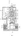
图2为依据本实用新型一较佳实施例而成的电磁阀纵断面图,显示在正常阀位的状态。Fig. 2 is a longitudinal sectional view of the solenoid valve according to a preferred embodiment of the present invention, showing the state in the normal valve position.
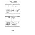
图3为本实用新型的动作流程图。Fig. 3 is the action flowchart of the utility model.
图4为与图2近似的断面图,显示按钮被按下时电磁阀的状态。Fig. 4 is a sectional view similar to Fig. 2, showing the state of the solenoid valve when the button is pressed.
图5为图4的后续动作断面图,显示手离开按钮时电磁阀的状态。Fig. 5 is a sectional view of the follow-up action in Fig. 4, showing the state of the solenoid valve when the hand leaves the button.
图6为本实用新型安装于瓦斯调节器的外观图。Fig. 6 is an appearance view of the utility model installed on a gas regulator.
图7为本实用新型安装于瓦斯管道的外观图。Fig. 7 is an appearance view of the utility model installed in a gas pipeline.
附图标记reference sign
10电磁阀 20壳体 21流体通路 22阀座10
23流入口 24流出口 25接头 26接头23 Inlet 24
27平台 28密合垫 29螺丝 30支架27
31第一支持部 32第二支持部 33轴孔 34杆孔31 First supporting
35密封环 40阀部 41滑轴 42阀体35
43第一导磁体 44第一弹簧 45连杆 46指示灯开关43
47致动片 50操作部 51梃杆 52杆头47 Actuating
53第二导磁体 54第二弹簧 55按钮 56电源开关53
60线圈 70壳盖 71孔洞 90瓦斯调节器60
95瓦斯管道95 gas pipeline
具体实施方式Detailed ways
在图2中,显示一电磁阀10处于正常阀位的内部构造,可供说明本实用新型的技术内容。该电磁阀10由一壳体20、一支架30、一阀部40、一操作部50、一线圈60及一壳盖70组成。其中,该壳体20具有一流体通路21,该流体通路21的内部形成有一阀座22,并且在它的流入口23和流出口24分别形成有供连接管件(图未示)的螺纹接头25和26;其它型式的接头亦可采用,不受螺纹的限制。该壳体20还提供一平台27,供将支架30及壳盖70固定在壳体20之上。In FIG. 2 , the internal structure of a
所述的支架30被螺丝(图未示)锁紧在壳体20之上,而且通过一密合垫28在两者的接触面间形成可靠的气密,藉以防止流体泄漏。该支架30具有相对的第一支持部31和第二支持部32;其中,第一支持部31具有一轴孔33,第二支持部提供一杆孔34,该轴孔33和杆孔34在同一轴线,以支持阀部40及操作部50为直线运动。The
上述阀部40包含一滑轴41穿过支架30的轴孔33而支持于第一支持部31滑动,并且滑轴41外周圈套一密封环35,可以在滑轴41和轴孔33的接触面间产生良好的气密性。该滑轴41的前端为用以开闭流体通路21的阀体42,后端具有一第一导磁体43,并具有一第一弹簧44圈套在该滑轴41的外周,该弹簧44的一端支持于阀体42,相对端支持于支架30的第一支持部31;上述第一导磁体43的外形大致上成“-”形;第一弹簧44为压缩力发生作用的压力弹簧,以利用其弹性力将阀体42保持在与阀座22密合的位置(即闭阀位),截断流体通路21。The above-mentioned
所述的操作部50包含一梃杆51穿过支架30的杆孔34而支持于第二支持部32向着阀部40滑动,该梃杆51的头部扩大形成一杆头52,并具有一第二导磁体53连结于该梃杆51的尾端,及一第二弹簧54圈套在该梃杆51的外周,该第二弹簧54的两端分别支持于梃杆51的杆头52及支架30的第二支持部32。另外,还有一按钮55安装在梃杆51的杆头52之上,并且突出于壳盖70外供手操作。上述第二导磁体53的外形大致上成倒“E”形;第二弹簧54亦为压缩力发生作用的压力弹簧, 以利用其弹性力将第二导磁体53保持在离开第一导磁体43的位置,而且第二弹簧54的弹性力大于第一弹簧44的弹性力,其作用留待后述。The
所述的线圈60固定在阀部40之上,而介于第一导磁体43和第二导磁体53之间,随着阀部40同步运动,并且电性连接一控制电路(图未示),使线圈60可从该控制电路获得电流,产生所要的电磁场,相反的电流被切断时,电磁场消失。上述控制电路设置于一固定在支架30侧边的电路板(图未示)之上,用来驱动电磁阀10作『开』或『闭』的动作,其中开启动作必须配合人工操作,其细节同样留待后述,暂且表过。由于控制电路不在本实用新型的讨论范围之内,故进一步说明实无必要。The
本实用新型还能通过操作部50的运动去控制一电源开关56作『ON』『OFF』动作,以接通、切断连接至控制电路的电源。在附图的实施例中,该电源开关使用按钮开关,它设置在按钮55的运动路径内,可以因为操作按钮55而被按下,达到接通、切断控制电路电源的目的。The utility model can also control a
本实用新型又可通过阀部40的运动去控制一指示灯开关46作『ON』『OFF』动作,使一电性连接该指示灯开关46的指示灯(图未示)亮灭。在附图的实施例中,该指示灯开关46使用微动开关,它的致动片47受一连结在滑轴41的连杆45控制,该连杆45可以随着滑轴41的移动而压下、释放致动片47,使微动开关的a接点开闭,达到控制指示灯亮灭的目的。所述指示灯可为发光二极管作成。The utility model can control an indicator
所述的壳盖70用螺丝29(参见图6)锁紧在壳体20的平台27之上,以保护包括上述支架30、第一导磁体43、操作部50、线圈60、电源开关56、指示灯开关46及控制电路在内的组件。The
图3为电磁阀10的动作流程,图4为按下按钮55时电磁阀10的状态,图5为手离开按钮55时电磁阀10的状态。FIG. 3 is the action flow of the
按照本实用新型的电磁阀10,按下操作部50的按钮55时,操作部50会向着阀部40移动,同时电源开关56被按钮55压下而接通控制电路的电源,于是从控制电路供给一电压至线圈60,使线圈60通过电流而在四周产生电磁场,将处于该电磁场内的第二导磁体53变成电磁铁,并与第一导磁体43相互吸引。According to the
当手离开按钮55时,整个操作部50因第二弹簧54的弹性力而复归原位,同时带动阀部40及线圈60移动,使阀体42作动成开阀位而开启流体通路21。When the hand leaves the
因为第二弹簧54的弹性力大于第一弹簧44的弹性力,故能确保在第一导磁体43被第二导磁体53吸引时,阀体42可以完全地打开,不会因为第一弹簧44的弹性回复力而复归闭阀位,截断流体通路21。当然,如果第一导磁体43和第二导磁体53的相互吸引力大于第一弹簧44的弹性力,则第二弹簧54的弹性力不一定要大于第一弹簧44的弹性力。Because the elastic force of the
另一方面,当阀部40被电磁力吸引而位移时,连杆45会同时压下指示灯开关46的致动片47使其a接点闭合,因而接通连接至指示灯的电路点亮指示灯,发出一电磁阀10处于开启阀位的视觉信号。On the other hand, when the
在电磁阀10作用成开阀位的情形下,有二种方法可以将它关闭。一种是人工操作,一种是自动操作。其中:人工操作是用手再按一次按钮55然后放开,此时控制电路的电源因电源开关56再次被操作而中断,据此切断线圈60的电流,于是阀部40因电磁铁的吸引力消失而被第一弹簧44的弹性力推回原位,使阀体42密着于阀座22而截断流体通路21,同时操作部50因为手离开按钮55而利用第二弹簧54的弹性力复归原位。自动操作是利用控制电路发生作用时,切断线圈60的电流,使阀部40因电磁力消失而藉助第一弹簧43的弹性力复归闭阀位,截断流体通路21。With the
至于指示灯开关46,不论是人工控制或自动控制,它的a接点在阀部40回复原位时,会因为致动片47被连杆45释放而打开,使指示灯熄灭。As for the indicator
图6和图7显示电磁阀10分别安装于瓦斯调节器90和瓦斯管道95的外观图。6 and 7 show the external views of the
当然,上述实施例可在不脱离本实用新型的范围内加以若干变化,故以上的说明所包含及附图中所示的全部事项应视为例示性,而非用以限制本实用新型的申请专利范围。Of course, the above-mentioned embodiments can be changed without departing from the scope of the present utility model, so all matters contained in the above description and shown in the accompanying drawings should be regarded as illustrative rather than limiting the application of the present utility model patent scope.
Claims (15)
Translated fromChinesePriority Applications (1)
| Application Number | Priority Date | Filing Date | Title |
|---|---|---|---|
| CNU2007201734864UCN201093081Y (en) | 2007-09-29 | 2007-09-29 | Electromagnetic valve |
Applications Claiming Priority (1)
| Application Number | Priority Date | Filing Date | Title |
|---|---|---|---|
| CNU2007201734864UCN201093081Y (en) | 2007-09-29 | 2007-09-29 | Electromagnetic valve |
Publications (1)
| Publication Number | Publication Date |
|---|---|
| CN201093081Ytrue CN201093081Y (en) | 2008-07-30 |
Family
ID=39901048
Family Applications (1)
| Application Number | Title | Priority Date | Filing Date |
|---|---|---|---|
| CNU2007201734864UExpired - Fee RelatedCN201093081Y (en) | 2007-09-29 | 2007-09-29 | Electromagnetic valve |
Country Status (1)
| Country | Link |
|---|---|
| CN (1) | CN201093081Y (en) |
Cited By (3)
| Publication number | Priority date | Publication date | Assignee | Title |
|---|---|---|---|---|
| CN102359653A (en)* | 2011-10-22 | 2012-02-22 | 上海埃科燃气测控设备有限公司 | Mechanism for displaying opening and closing states of electromagnetic valve and display method of mechanism |
| CN105370916A (en)* | 2015-12-04 | 2016-03-02 | 浙江恒居防爆电气科技有限公司 | Gas emergency shut-off valve |
| CN111297306A (en)* | 2019-12-05 | 2020-06-19 | 重庆金山医疗技术研究院有限公司 | Suction assembly for endoscope and endoscope |
- 2007
- 2007-09-29CNCNU2007201734864Upatent/CN201093081Y/ennot_activeExpired - Fee Related
Cited By (4)
| Publication number | Priority date | Publication date | Assignee | Title |
|---|---|---|---|---|
| CN102359653A (en)* | 2011-10-22 | 2012-02-22 | 上海埃科燃气测控设备有限公司 | Mechanism for displaying opening and closing states of electromagnetic valve and display method of mechanism |
| CN105370916A (en)* | 2015-12-04 | 2016-03-02 | 浙江恒居防爆电气科技有限公司 | Gas emergency shut-off valve |
| CN105370916B (en)* | 2015-12-04 | 2018-10-02 | 浙江恒居防爆电气科技有限公司 | A kind of gas emergency cut-off valve |
| CN111297306A (en)* | 2019-12-05 | 2020-06-19 | 重庆金山医疗技术研究院有限公司 | Suction assembly for endoscope and endoscope |
Similar Documents
| Publication | Publication Date | Title |
|---|---|---|
| CN1281523A (en) | Self-closing solenoid operated faucet | |
| CN101918743B (en) | Flow control valve | |
| CN201093081Y (en) | Electromagnetic valve | |
| US20110232627A1 (en) | Safety Gas Valve | |
| EP1909029A3 (en) | Safety electromagnetic valve with internal spring | |
| JP2017075657A (en) | safety valve | |
| TWM330396U (en) | Solenoid valve | |
| JP2018128198A (en) | Gas combustion apparatus | |
| JP2018013251A (en) | Gas valve device | |
| JP2009228785A (en) | Motor safety valve | |
| KR100945166B1 (en) | Electro controled gas | |
| CN216045459U (en) | Permanent-magnet gas cut-off valve | |
| RU2282090C1 (en) | Solenoid-operated valve | |
| RU137759U1 (en) | AUTOMATIC BLOCK VALVE DRIVE | |
| JP5465211B2 (en) | Gas shut-off valve and motor safety valve | |
| RU103161U1 (en) | ELECTROMAGNETIC VALVE | |
| CN222102889U (en) | A normally open gas shut-off valve | |
| CN111322417A (en) | An intelligent manual fire extinguisher solenoid valve | |
| JP4021079B2 (en) | Gas emission preventer | |
| CN209839286U (en) | Natural gas safety valve | |
| JPH0794874B2 (en) | Gas pipeline opening / closing valve for gas appliances | |
| CN210716013U (en) | Electromagnetic valve and gas stove | |
| JP4526437B2 (en) | Motor safety valve | |
| CN110195787B (en) | Solenoid valve | |
| CN222458441U (en) | Rocker arm type pinch valve |
Legal Events
| Date | Code | Title | Description |
|---|---|---|---|
| C14 | Grant of patent or utility model | ||
| GR01 | Patent grant | ||
| C17 | Cessation of patent right | ||
| CF01 | Termination of patent right due to non-payment of annual fee | Granted publication date:20080730 Termination date:20120929 |