CN201092023Y - Improved hand tool set fitting - Google Patents
Improved hand tool set fittingDownload PDFInfo
- Publication number
- CN201092023Y CN201092023YCNU2007200692756UCN200720069275UCN201092023YCN 201092023 YCN201092023 YCN 201092023YCN U2007200692756 UCNU2007200692756 UCN U2007200692756UCN 200720069275 UCN200720069275 UCN 200720069275UCN 201092023 YCN201092023 YCN 201092023Y
- Authority
- CN
- China
- Prior art keywords
- hand tool
- utility
- model
- section
- improved hand
- Prior art date
- Legal status (The legal status is an assumption and is not a legal conclusion. Google has not performed a legal analysis and makes no representation as to the accuracy of the status listed.)
- Expired - Fee Related
Links
- 238000005096rolling processMethods0.000abstractdescription5
- 238000000034methodMethods0.000abstractdescription3
- 239000003973paintSubstances0.000abstractdescription2
- 238000010586diagramMethods0.000description2
- 230000000694effectsEffects0.000description2
- 238000003780insertionMethods0.000description2
- 230000037431insertionEffects0.000description2
- 238000004519manufacturing processMethods0.000description2
- 238000007792additionMethods0.000description1
- 230000002730additional effectEffects0.000description1
- 230000000712assemblyEffects0.000description1
- 238000000429assemblyMethods0.000description1
- 238000006243chemical reactionMethods0.000description1
- 238000010276constructionMethods0.000description1
- 238000006073displacement reactionMethods0.000description1
- 239000000463materialSubstances0.000description1
Images


Landscapes
- Eyeglasses (AREA)
Abstract
Description
Translated fromChinese技术领域technical field
本实用新型与一种手工具组配件的结构有关,更详而言之,特别是指一种可防止非预期滚动且易于使用者所握持并供快速旋动,同时,更具有可供辨识品名、尺寸、规格,甚至供做企业识别标签用途的新颖设计。The utility model is related to the structure of a hand tool assembly, more specifically, it refers to a hand tool assembly that can prevent unexpected rolling and is easy for users to hold and rotate quickly. At the same time, it has more features for identification Product names, sizes, specifications, and even novel designs for corporate identification labels.
背景技术Background technique
所谓手工具的组配件泛指套筒、接杆、转接头、万向接头及压配套筒等施力用手工具(如起子、扳手、棘轮手工具等)的附属配件,通过两者间的插接使用,以对螺丝工件进行旋动作业。而综观现有的所有此类组配件,都因贪图于制造上的方便性及经济性,而将其最大外轮廓部位(即等同于使用者所握持的特定部位)设为光滑圆柱状体。The so-called assembly parts of hand tools generally refer to the accessories of hand tools (such as screwdrivers, wrenches, ratchet hand tools, etc.) It is used for plugging in to rotate the screw workpiece. Looking at all the existing components of this type, because of the convenience and economy in manufacturing, the largest outer contour part (that is, the specific part that is equivalent to the user's grip) is set as a smooth cylindrical body. .
于是,虽说此一制造上的惯例已被沿用数十年不变,也早为使用者习以为常,然而就实际使用情况而言,由于该部位呈圆柱状,故常会在横置摆放时,发生非预期的滚动位移,致使使用者必须时时注意其所在位置,甚至要分心搜寻,而造成施工作业上的极度不便与耽搁;同时,在大多布满油污的作业环境下,使用者的手指必然可能也沾有油渍,而难以好好握持该等具光滑表面的组配件,因此,除了常会发生非预期的滑脱现象外,使用者更难以用手指进行快速的旋动作业;由此可知,该等习知设计诚有被加以改进的必要性及迫切性。Therefore, although this manufacturing practice has been used unchanged for decades and has long been used by users, in terms of actual use, because the part is cylindrical, it often occurs when placed horizontally. The unanticipated rolling displacement makes the user have to pay attention to its location all the time, and even distractedly search, which causes extreme inconvenience and delay in construction work; at the same time, in most oil-stained working environments, the user's fingers must inevitably It may also be stained with oil stains, and it is difficult to hold these components with smooth surfaces. Therefore, in addition to unexpected slippage, it is more difficult for users to perform fast rotation operations with fingers; it can be seen that the There is a necessity and an urgency to improve conventional designs.
发明内容Contents of the invention
为此,设计人基于上述实情,并凭其多年来熟知此行业的实务经验,特别针对所有手工具组配件的最大外轮廓部位施予形状及构造上的改进,期能一举消除习用产品在使用上的诸多不便,防止非预期滚动且易于使用者所握持并供快速旋动,由此增加其使用便利性与实用性,此为本实用新型的主要目的。For this reason, based on the above facts and years of practical experience in this industry, the designer specially improved the shape and structure of the largest outer contour parts of all hand tool assemblies, hoping to eliminate the use of conventional products in one fell swoop. The main purpose of this utility model is to prevent unexpected rolling and be easy for users to hold and quickly rotate, thereby increasing its convenience and practicality.
为达上述目的,本实用新型改进的手工具组配件,泛指套筒、接杆、转接头、万向接头及压配套筒等施力用手工具的附属配件;而其主要使该任一组配件的最大外轮廓部位成多边形柱状断面,并使每一相邻断面间都具有止滑刻纹;其更可于该柱状断面间开设一道以上的环槽沟。In order to achieve the above purpose, the improved hand tool assembly accessories of the present utility model generally refer to the accessory accessories of hand tools for applying force such as sleeves, extension rods, adapters, universal joints and press-fitting sleeves; and it mainly makes any The largest outer contour of the assembly part is a polygonal columnar section, and each adjacent section has anti-slip grooves; more than one ring groove can be opened between the columnar sections.
本实用新型使任一组配件的最大外轮廓部位成多边形柱状断面(如四角柱状、六角柱状、八角柱状等),并使每一相邻断面间都具有止滑刻纹,进而达成防止非预期滚动且易于使用者所握持并供快速旋动等实用效益;为增加此类组配件的附加功效,在该最大外轮廓部位另设有一道以上的环槽沟,可作为辨识品名、尺寸、规格,甚至供做企业识别标签等积极用途。The utility model makes the largest outer contour of any group of accessories into a polygonal columnar section (such as square columnar, hexagonal columnar, octagonal columnar, etc.), and makes each adjacent section have anti-slip engravings, thereby preventing unexpected Rolling and easy for users to hold and provide practical benefits such as fast rotation; in order to increase the additional effect of this type of assembly, there is more than one ring groove on the largest outer contour part, which can be used to identify the product name, size, specifications, and even for active uses such as corporate identification labels.
附图说明Description of drawings
图1:为本实用新型第一较佳实施例的立体示意图;Fig. 1: is the three-dimensional schematic diagram of the first preferred embodiment of the utility model;
图2:为依图1所示较佳实施例的平面示意图;Fig. 2: is the schematic plan view according to the preferred embodiment shown in Fig. 1;
图3:为本实用新型第二较佳实施例的立体示意图;Fig. 3: is the three-dimensional schematic view of the second preferred embodiment of the utility model;
图4:为本实用新型第三较佳实施例的立体示意图;Fig. 4: is the three-dimensional schematic diagram of the third preferred embodiment of the present invention;
图5:为本实用新型第四较佳实施例的立体示意图;Fig. 5: is the three-dimensional schematic view of the fourth preferred embodiment of the utility model;
图6:为本实用新型第五较佳实施例的立体示意图;Fig. 6: is the three-dimensional schematic view of the fifth preferred embodiment of the utility model;
图7:为本实用新型第六较佳实施例的立体示意图;Fig. 7: is the three-dimensional schematic view of the sixth preferred embodiment of the present invention;
图8:为本实用新型第七较佳实施例的立体示意图。Fig. 8: It is a three-dimensional schematic view of the seventh preferred embodiment of the present invention.
具体实施方式Detailed ways
为使进一步深入了解本实用新型的技术手段与结构特征,兹配合附图详述于后:In order to further understand the technical means and structural features of the present utility model, it is hereby described in detail in conjunction with the accompanying drawings:
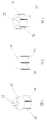
首先,如图1、2所示,为本实用新型的第一较佳实施例图,由图可知,该组配件为一套筒10,在一端设有工具插接孔12,另端则具有作用套孔(图未示);其主要使最大外轮廓部位成多边形柱状断面14,并使每一相邻断面14间都具有止滑刻纹16,进而达成预期效能。At first, as shown in Fig. 1, 2, it is the first preferred embodiment figure of the present utility model, as can be seen from the figure, this group of fittings is a
又如图3所示,为本实用新型的第二较佳实施例图,该组配件为另一类型套筒20,其同样在一端设有工具插接孔22,另端则具有作用套孔(图未示);而在最大外轮廓部位也成多边形柱状断面24,并于相邻断面24间都设有止滑刻纹26。As shown in Figure 3 again, it is the second preferred embodiment figure of the present utility model, and this group of accessories is another type of
而图4、5所示,为本实用新型的第三、四较佳实施例图,该组配件分别为转接头30及压配套筒40,而同样可将最大外轮廓部位设成多边形柱状断面34、44,以及在相邻断面34、44间设置止滑刻纹36、46。And shown in Fig. 4, 5, it is the 3rd, 4th preferred embodiment figure of the present utility model, and this group of parts is respectively adapter 30 and press-
再如图6、7所示,为本实用新型的第五、六较佳实施例图,该组配件分别为万向接头50及延长接杆60,而依然可以适用本实用新型的设计。As shown in Figures 6 and 7 again, they are the fifth and sixth preferred embodiment drawings of the present utility model. The accessories are
之后,还请参阅图8所示,本实用新型也可在任一组配件80的柱状断面82适当处,开设一道以上的环槽沟84,由此配合于环槽沟84处所涂布的有色漆料,使成辨识品名、尺寸、规格,甚至共做企业识别标签之用。Afterwards, please also refer to shown in Fig. 8, the utility model also can set more than one
由于本实用新型可运用的范畴极为广泛,而几乎能涵盖所有手工具的组配件,但设计人诚难以一一以附图表示,故举凡利用本实用新型设计特征所为的简易附加与等效转换手法,当仍应隶属本实用新型的专利范畴。Because the utility model can be used in a very wide range, and can cover almost all hand tool components, but it is difficult for the designer to show them one by one with the accompanying drawings, so all the simple additions and equivalents made by utilizing the design features of the utility model Conversion technique should still belong to the patent category of the present utility model.
综观以上所言,本实用新型确实具有诸多实质功效增进的事实,且其申请前未见于市售物品相关刊物文献。In view of the above, the utility model does have the fact that many substantial effects are improved, and it has not been seen in publications related to commercially available items before its application.
Claims (2)
Translated fromChinesePriority Applications (1)
| Application Number | Priority Date | Filing Date | Title |
|---|---|---|---|
| CNU2007200692756UCN201092023Y (en) | 2007-04-24 | 2007-04-24 | Improved hand tool set fitting |
Applications Claiming Priority (1)
| Application Number | Priority Date | Filing Date | Title |
|---|---|---|---|
| CNU2007200692756UCN201092023Y (en) | 2007-04-24 | 2007-04-24 | Improved hand tool set fitting |
Publications (1)
| Publication Number | Publication Date |
|---|---|
| CN201092023Ytrue CN201092023Y (en) | 2008-07-30 |
Family
ID=39899985
Family Applications (1)
| Application Number | Title | Priority Date | Filing Date |
|---|---|---|---|
| CNU2007200692756UExpired - Fee RelatedCN201092023Y (en) | 2007-04-24 | 2007-04-24 | Improved hand tool set fitting |
Country Status (1)
| Country | Link |
|---|---|
| CN (1) | CN201092023Y (en) |
Cited By (7)
| Publication number | Priority date | Publication date | Assignee | Title |
|---|---|---|---|---|
| CN102374923A (en)* | 2010-08-23 | 2012-03-14 | 浙江吉利汽车有限公司 | Torque calibrator for multifunctional wrench |
| CN102751593A (en)* | 2011-04-19 | 2012-10-24 | 深圳市宏商材料科技股份有限公司 | Conductor connector |
| CN103957480A (en)* | 2014-03-31 | 2014-07-30 | 刘骏涛 | Portable mini loudspeaker box |
| CN103957479A (en)* | 2014-03-31 | 2014-07-30 | 刘骏涛 | Portable mini loudspeaker box |
| CN103957481A (en)* | 2014-03-31 | 2014-07-30 | 刘骏涛 | Portable mini loudspeaker box |
| CN105171689A (en)* | 2015-09-09 | 2015-12-23 | 北京汽车研究总院有限公司 | Double-screw bolt installation adaptor |
| CN109267814A (en)* | 2018-10-08 | 2019-01-25 | 杨相宜 | A kind of hand-held automatic lifting flag device |
- 2007
- 2007-04-24CNCNU2007200692756Upatent/CN201092023Y/ennot_activeExpired - Fee Related
Cited By (9)
| Publication number | Priority date | Publication date | Assignee | Title |
|---|---|---|---|---|
| CN102374923A (en)* | 2010-08-23 | 2012-03-14 | 浙江吉利汽车有限公司 | Torque calibrator for multifunctional wrench |
| CN102374923B (en)* | 2010-08-23 | 2014-06-04 | 浙江吉利汽车有限公司 | Torque calibrator for multifunctional wrench |
| CN102751593A (en)* | 2011-04-19 | 2012-10-24 | 深圳市宏商材料科技股份有限公司 | Conductor connector |
| CN102751593B (en)* | 2011-04-19 | 2016-07-06 | 深圳市宏商材料科技股份有限公司 | A kind of conductor connector |
| CN103957480A (en)* | 2014-03-31 | 2014-07-30 | 刘骏涛 | Portable mini loudspeaker box |
| CN103957479A (en)* | 2014-03-31 | 2014-07-30 | 刘骏涛 | Portable mini loudspeaker box |
| CN103957481A (en)* | 2014-03-31 | 2014-07-30 | 刘骏涛 | Portable mini loudspeaker box |
| CN105171689A (en)* | 2015-09-09 | 2015-12-23 | 北京汽车研究总院有限公司 | Double-screw bolt installation adaptor |
| CN109267814A (en)* | 2018-10-08 | 2019-01-25 | 杨相宜 | A kind of hand-held automatic lifting flag device |
Similar Documents
| Publication | Publication Date | Title |
|---|---|---|
| CN201092023Y (en) | Improved hand tool set fitting | |
| US20170312839A1 (en) | Tap holder for multiple tap sizes | |
| US20160193724A1 (en) | Socket Spanner | |
| CN204171946U (en) | Screw fixed cover and screwdriver | |
| CN103582543A (en) | Dismantleable tubular gripping element | |
| CN100548583C (en) | Adjustable torque screwdriver | |
| CN203680181U (en) | Antiskid wrench socket | |
| JP3123455U (en) | Tools with identification color | |
| US20070151426A1 (en) | Hex wrench | |
| CN201168945Y (en) | Improved structure for screwdriver | |
| TWI806620B (en) | Non-slip grip structure | |
| CN202952194U (en) | Wrench with screwdriver function | |
| CN202423966U (en) | Pin taking device of insulator | |
| WO2005067624A2 (en) | Non-marring tools | |
| CN101402193A (en) | Multifunctional combined tool hammer | |
| CN206952846U (en) | A kind of box spanner for being convenient for changing sleeve | |
| TWM457613U (en) | Improved tool bit with identification structure | |
| CN101870371A (en) | Jig for pasting protective film of electronic product | |
| TWM631576U (en) | Anti-slip grip structure | |
| CN201253825Y (en) | Improved hand tool set fitting | |
| CN205870389U (en) | Universal socket wrench | |
| TWM486523U (en) | Unidirectional bearing wrench adapter sleeve | |
| CN203792292U (en) | Tool | |
| CN212578475U (en) | Bearing cap locating pin for speed reducer | |
| TWM550677U (en) | Improved handle structure of screw driver |
Legal Events
| Date | Code | Title | Description |
|---|---|---|---|
| C14 | Grant of patent or utility model | ||
| GR01 | Patent grant | ||
| C17 | Cessation of patent right | ||
| CF01 | Termination of patent right due to non-payment of annual fee | Granted publication date:20080730 Termination date:20140424 |