CN201088231Y - Braking mechanism for braking wheel of luggage - Google Patents
Braking mechanism for braking wheel of luggageDownload PDFInfo
- Publication number
- CN201088231Y CN201088231YCNU2007200579382UCN200720057938UCN201088231YCN 201088231 YCN201088231 YCN 201088231YCN U2007200579382 UCNU2007200579382 UCN U2007200579382UCN 200720057938 UCN200720057938 UCN 200720057938UCN 201088231 YCN201088231 YCN 201088231Y
- Authority
- CN
- China
- Prior art keywords
- pull rod
- sliding seat
- brake wheel
- pull
- brake
- Prior art date
- Legal status (The legal status is an assumption and is not a legal conclusion. Google has not performed a legal analysis and makes no representation as to the accuracy of the status listed.)
- Expired - Fee Related
Links
Images


Landscapes
- Purses, Travelling Bags, Baskets, Or Suitcases (AREA)
Abstract
Description
Translated fromChinese技术领域:Technical field:
本实用新型涉及行李箱技术领域,特指一种行李箱之刹车轮制动机构。The utility model relates to the technical field of luggage, in particular to a brake wheel brake mechanism of a luggage.
背景技术:Background technique:
带轮子的行李箱已为多数旅客采用,这是因为他们可以牵拉着重载的箱子而不需要提拿,便于旅途行走。现有技术中,带轮子的行李箱主要有两种,一种是“后轮式”,箱体底部前端有支撑脚,后端两侧设有直线式、不可360度旋转的滚轮;另一种是“四轮式”,即箱体底部四角设有可旋转360度的滚轮。尽管带轮子的行李箱很普遍,但绝大部分先前这类带轮子的行李箱,其滚轮没有刹车功能,这样对于四轮式行李箱则很难站立静止定位,而对于后轮式行李箱则依靠前端支撑脚配合后轮站立定位,但依然会出现后轮滚动而定位不稳的情况,这些都给使用上带来不便,使用者不能任意停放行李箱。The suitcase with wheels has been adopted by most passengers, and this is because they can pull heavy-duty suitcases without lifting them, which is convenient for traveling. In the prior art, there are mainly two types of suitcases with wheels. One is the "rear wheel type". The second is the "four-wheel type", that is, the four corners of the bottom of the box are equipped with rollers that can rotate 360 degrees. Although wheeled luggage is very common, most of the previous wheeled luggage has no brake function on its rollers, which makes it difficult to stand still for four-wheeled luggage and difficult for rear-wheeled luggage. Relying on the front-end support feet to cooperate with the rear wheels to stand and position, but the rear wheels still roll and the positioning is unstable, which brings inconvenience to the use, and the user cannot park the suitcase arbitrarily.
随后出现有带刹车轮的行李箱,其轮子上带有制动块,由制动块摩擦或卡制轮子,使之停止转动,从而达到刹车的目的。然而,现有技术中,对于制动块的操作存在有操作不便,且制动稳定性不高的缺陷,不利于实际使用刹车轮。Then there is a suitcase with a brake wheel, which has a brake block on its wheel, and the wheel is rubbed or clamped by the brake block to stop it from rotating, thereby achieving the purpose of braking. However, in the prior art, the operation of the brake pads has the disadvantages of inconvenient operation and low braking stability, which is not conducive to the actual use of the brake wheel.
发明内容:Invention content:
本实用新型的目的在于克服现有技术的缺陷,提供一种便于操作,且制动稳定的行李箱之刹车轮制动机构。The purpose of the utility model is to overcome the defects of the prior art, and to provide a brake wheel brake mechanism of a suitcase which is easy to operate and stable in braking.
本实用新型另一目的在于提供一种可匹配拉杆收缩动作进行刹车制动的行李箱之刹车轮制动机构。Another object of the present utility model is to provide a brake wheel brake mechanism for suitcases that can match the retraction action of the pull rod to brake.
为达到上述目的,本实用新型所述的行李箱之刹车轮制动机构,包括拉杆及相关刹车轮组,一联动刹车轮制动块的拉线横向贯穿拉杆,由此拉线在拉杆内中部形成有一架桥段;一滑动座设置在拉杆内中部,且位于拉线之架桥段上方,滑动座可由拉杆之内管内缩推动而下压拉线之架桥段,籍此收拉拉线而制动刹车轮。In order to achieve the above purpose, the brake wheel braking mechanism of the suitcase described in the utility model includes a pull rod and related brake wheel sets. The bridging section; a sliding seat is set in the middle of the tie rod, and is located above the bridging section of the pull wire. The sliding seat can be pushed by the inner tube of the pull rod to push down the bridging section of the pull wire, so that the pull wire is pulled and the brake wheel is braked. .
滑动座与拉线之架桥段接触顶压的部分为一柔性触头,柔性触头之顶压端上设有一弧槽钳制拉线之架桥段。The part where the sliding seat and the bridging section of the backguy wire are in contact with the top pressure is a flexible contact, and the top pressure end of the flexible contact is provided with an arc groove to clamp the bridging section of the backguy wire.
滑动座设有门形槽供柔性触头容置,柔性触头通过其侧面上的凸轴挂接在滑动座上,且滑动座上有竖直长槽提供柔性触头之凸轴上下移动的空间,柔性触头内端成型为销轴并套接一压缩弹簧,压缩弹簧提供柔性触头竖向浮动之特性。The sliding seat is provided with a door-shaped groove for the flexible contact to be accommodated. The flexible contact is hung on the sliding seat through the protruding shaft on its side, and there is a vertical long groove on the sliding seat to provide the protruding shaft of the flexible contact to move up and down. Space, the inner end of the flexible contact is shaped as a pin shaft and is sleeved with a compression spring, which provides the characteristic of vertical floating of the flexible contact.
滑动座上设有弹性扣与拉杆相应位置上的扣孔定位;滑动座上还设有下滑到位之止顶部,该止顶部与拉杆相应位置的内凸部卡止,拉杆的内凸部由一外部锁入的螺钉构成。The sliding seat is provided with an elastic buckle and the buckle hole positioning on the corresponding position of the pull rod; the sliding seat is also provided with a stop top that slides into place, and the stop top is locked with the inner convex part of the corresponding position of the pull rod. External locking screw construction.
本实用新型通过有效地结构设计,利用拉杆收缩之动力来驱动滑动座,并由滑动座带动拉线收拉,进而实现刹车轮制动刹车,该结构简单,操作方便,可稳定制止轮子,可以使行李箱站立定位,不至于随意滑移,避免行李箱无意中滑走的尴尬事件,刹车动作与拉杆回收动作相匹配,具有良好的操控性。The utility model uses the power of the pull rod contraction to drive the sliding seat through effective structural design, and the sliding seat drives the cable to retract, thereby realizing the braking of the brake wheel. The structure is simple, the operation is convenient, the wheel can be stably stopped, and the The suitcase is positioned in a standing position, so that it will not slide randomly, avoiding the embarrassing event that the suitcase slips away unintentionally. The braking action matches the pull rod recovery action, which has good controllability.
附图说明:Description of drawings:
附图1为本实用新型外形示意图;Accompanying drawing 1 is a schematic diagram of the appearance of the utility model;
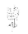
附图2为本实用新型立体分解结构示意图;Accompanying drawing 2 is the three-dimensional decomposition structure schematic diagram of the utility model;
附图3为本实用新型之滑动座立体结构示意图;Accompanying drawing 3 is the schematic diagram of the three-dimensional structure of the sliding seat of the present invention;
附图4为本实用新型组合结构示意图;Accompanying drawing 4 is the combined structure schematic diagram of the present utility model;
附图5为本实用新型未刹车状态示意图;Accompanying drawing 5 is the schematic diagram of the non-braking state of the utility model;
附图6为本实用新型刹车状态示意图;Accompanying drawing 6 is the schematic diagram of braking state of the present utility model;
附图7为本实用新型在刹车负荷过大时的状态示意图。Accompanying drawing 7 is the state diagram of the utility model when the brake load is too large.
具体实施方式:Detailed ways:
以下结合附图对本实用新型做进一步说明:Below in conjunction with accompanying drawing, the utility model is further described:
见附图1~5所示,本实用新型所述的行李箱之刹车轮制动机构,包括拉杆10及相关刹车轮组(图中未示),拉杆10系由内管和外管组成的伸缩杆体,以达到拉伸使用,收缩存放的功效。一联动刹车轮制动块的拉线20横向贯穿拉杆10,本实施例中,拉线20贯穿的是拉杆10的最外管,拉线20在拉杆10内中部形成有一架桥段21。在拉杆10外的拉线20有外壳套包覆,外壳套具有保护和美观的作用,拉线20可在外壳套内伸缩;于拉线20与拉杆10触接处结合有一防护头22,防护头22安置于拉杆10上。本实施例中,为了配合安装,拉杆10上开设有异形孔11,异形孔11上端的大孔方便防护头22穿设,而异形孔11下端的小孔方便防护头22卡设而固定。See shown in accompanying drawing 1~5, the brake wheel braking mechanism of suitcase described in the utility model comprises
一滑动座30设置在拉杆10内中部,且位于拉线20之架桥段21上方,滑动座30可由拉杆10之内管内缩推动而下压拉线20之架桥段21,籍此收拉拉线20而制动刹车轮。拉线20外伸的两端头分别系接行李箱左右刹车轮组上的制动块,制动块与轮子可采用摩擦刹车或卡制刹车,如类似自行车或摩托车等方式刹车,当然也不局限于此,只要是可通过拉线收拉动作来驱动制动刹车的结构均可。A sliding
滑动座30与拉线20之架桥段21接触顶压的部分为一柔性触头31,柔性触头31之顶压端上设有一弧槽311钳制拉线之架桥段21。本实施例中,滑动座30设有门形槽32供柔性触头31容置,柔性触头31通过其侧面上的凸轴312挂接在滑动座30上,且滑动座30上有竖直长槽33提供柔性触头31之凸轴312上下移动的空间,柔性触头31内端成型为销轴并套接一压缩弹簧34,压缩弹簧34提供柔性触头31竖向浮动之特性,柔性触头31之凸轴312具有导引和限制柔性触头31活动的作用,柔性触头31在压缩弹簧34提供的弹性作用下,其与拉线20之架桥段21触接时具有缓冲和防震的作用。The part where the sliding
图6、7所示为本实用新型用于刹车的情形,其中图6所示为一般正常刹车情形,由拉杆10的相应内管内缩推动滑动座30下移,从而使滑动座30下压拉线20之架桥段21,架桥段21形变而收拉拉线20,由此通过拉线20带动刹车轮之相应制动块,实现刹车目的。图7所示为刹车负荷过大时的状态示意图,这时柔性触头31受力过大而往滑动座30内缩,压缩弹簧34给予内缩缓冲,而柔性触头31之凸轴312给予导引,确保柔性触头31与拉线20之架桥段21接触平稳,从而很好地收拉拉线20。柔性触头31之顶压端上有一弧槽311钳制拉线20,可防止打滑,加强柔性触头31与拉线20接触。本实用新型正是利用滑动座30下压拉线20之架桥段21来收拉拉线20,再由拉线20带动制动块制止行李箱轮子,而刹车动作与拉杆10收缩相匹配,即拉杆10收回则相应制止轮子,以便行李箱站立定位,不至于随意滑移,避免行李箱无意中滑走的尴尬事件。而拉出拉杆10,则松放滑动座30,拉线20之架桥段21复位拉直的同时抬起滑动座30,以便下次刹车之用;拉线20复位则放开行李箱轮子,即使用者可拉持行李箱移动,方便携带行李。Figures 6 and 7 show the situation of the utility model for braking, wherein Figure 6 shows the general normal braking situation, the sliding
图中,滑动座30上设有弹性扣35与拉杆10相应位置上的扣孔12定位。滑动座30上的弹性扣35对称分布,其中之一为一圆钢珠,另一为凸销,两者安装于相应的槽穴内,并有压缩弹簧支撑。图2所示,对于凸销型的弹性扣35,其利用斜面配合的方式操控伸缩,即在凸销中部设有斜面,在滑动座30上设有可匹配该斜面动作的推杆36,推杆36下推则利用斜面关系将凸销型弹性扣35压回,即缩进解扣而允许滑动座30上下移动,推杆36的下压动作可由拉杆10之相应内管内缩驱动;对于圆钢珠之弹性扣35只需要用力下推滑动座30即可实现解扣,结构简单,操作方便。In the figure, the sliding
本实用新型中,滑动座30上还设有下滑到位之止顶部37,该止顶部37与拉杆10相应位置的内凸部13卡止。该结构确定滑动座30下移的幅度,具有定位作用,可防止滑动座30下压过大。本实施例,拉杆10的内凸部13由一外部锁入的螺钉构成,从而简化加工结构,便于制作。In the present utility model, the sliding
Claims (7)
Translated fromChinesePriority Applications (1)
| Application Number | Priority Date | Filing Date | Title |
|---|---|---|---|
| CNU2007200579382UCN201088231Y (en) | 2007-09-29 | 2007-09-29 | Braking mechanism for braking wheel of luggage |
Applications Claiming Priority (1)
| Application Number | Priority Date | Filing Date | Title |
|---|---|---|---|
| CNU2007200579382UCN201088231Y (en) | 2007-09-29 | 2007-09-29 | Braking mechanism for braking wheel of luggage |
Publications (1)
| Publication Number | Publication Date |
|---|---|
| CN201088231Ytrue CN201088231Y (en) | 2008-07-23 |
Family
ID=39859987
Family Applications (1)
| Application Number | Title | Priority Date | Filing Date |
|---|---|---|---|
| CNU2007200579382UExpired - Fee RelatedCN201088231Y (en) | 2007-09-29 | 2007-09-29 | Braking mechanism for braking wheel of luggage |
Country Status (1)
| Country | Link |
|---|---|
| CN (1) | CN201088231Y (en) |
Cited By (2)
| Publication number | Priority date | Publication date | Assignee | Title |
|---|---|---|---|---|
| CN103222719A (en)* | 2013-04-09 | 2013-07-31 | 金泰祥精密五金(昆山)有限公司 | Luggage with manual control brake |
| WO2014166144A1 (en)* | 2013-04-08 | 2014-10-16 | 浙江爱美德旅游用品有限公司 | Trolley case having braking mechanism |
- 2007
- 2007-09-29CNCNU2007200579382Upatent/CN201088231Y/ennot_activeExpired - Fee Related
Cited By (3)
| Publication number | Priority date | Publication date | Assignee | Title |
|---|---|---|---|---|
| WO2014166144A1 (en)* | 2013-04-08 | 2014-10-16 | 浙江爱美德旅游用品有限公司 | Trolley case having braking mechanism |
| CN103222719A (en)* | 2013-04-09 | 2013-07-31 | 金泰祥精密五金(昆山)有限公司 | Luggage with manual control brake |
| CN103222719B (en)* | 2013-04-09 | 2015-05-13 | 金泰祥精密五金(昆山)有限公司 | Luggage with manual control brake |
Similar Documents
| Publication | Publication Date | Title |
|---|---|---|
| JP4757356B1 (en) | Caster lock device for bags | |
| CN201088231Y (en) | Braking mechanism for braking wheel of luggage | |
| CN104042014B (en) | A kind of button control formula brake gear of trolley luggage | |
| CN205728532U (en) | A kind of luggage case anti-skidding device | |
| CN201056136Y (en) | Brake wheel for luggage case | |
| CN209395780U (en) | A kind of passenger car hand brake operation mechanism assembly | |
| CN209359832U (en) | A kind of suitcase with universal wheel trolley that can be parked | |
| CN201089336Y (en) | Improved luggage case wheel seat | |
| CN107928054B (en) | Brake device of airplane wheel luggage case | |
| CN104337167B (en) | Retractable stationary stand with brake function for case or bag or bag | |
| CN105286250B (en) | A kind of portable stair climbing draw-bar box | |
| CN109527746B (en) | Draw-bar box capable of being dragged more labor-saving | |
| CN202909040U (en) | Improved structure of walking aid | |
| CN205197266U (en) | Draw -bar box | |
| CN212280260U (en) | Luggage case | |
| CN210234825U (en) | Automobile trunk bottom plate | |
| CN103213612A (en) | Automatic braking and control device of trolley | |
| CN205728531U (en) | A kind of Antislip luggage case body | |
| CN203279958U (en) | Suitcase with brake mechanism | |
| CN108515917A (en) | A kind of roof-rack of new-energy automobile | |
| CN2938013Y (en) | Band tape with automatic locking and rolling pressing structure | |
| CN210120940U (en) | Sliding-inhibiting luggage case | |
| CN212890534U (en) | Pet package pull rod shallow with brake function | |
| CN108357613B (en) | A folding scooter | |
| CN205220218U (en) | Brake wheelset structure |
Legal Events
| Date | Code | Title | Description |
|---|---|---|---|
| C14 | Grant of patent or utility model | ||
| GR01 | Patent grant | ||
| CF01 | Termination of patent right due to non-payment of annual fee | Granted publication date:20080723 Termination date:20150929 | |
| EXPY | Termination of patent right or utility model |