CN201080232Y - Rear frame of bicycle - Google Patents
Rear frame of bicycleDownload PDFInfo
- Publication number
- CN201080232Y CN201080232YCNU2007201516408UCN200720151640UCN201080232YCN 201080232 YCN201080232 YCN 201080232YCN U2007201516408 UCNU2007201516408 UCN U2007201516408UCN 200720151640 UCN200720151640 UCN 200720151640UCN 201080232 YCN201080232 YCN 201080232Y
- Authority
- CN
- China
- Prior art keywords
- rear frame
- long
- bicycle
- ribs
- long tube
- Prior art date
- Legal status (The legal status is an assumption and is not a legal conclusion. Google has not performed a legal analysis and makes no representation as to the accuracy of the status listed.)
- Expired - Fee Related
Links
- 239000000463materialSubstances0.000claimsabstractdescription6
- 239000011162core materialSubstances0.000claims1
- 239000000835fiberSubstances0.000abstractdescription9
- 229920005989resinPolymers0.000description7
- 239000011347resinSubstances0.000description7
- 239000004744fabricSubstances0.000description5
- 238000004519manufacturing processMethods0.000description3
- 229920000049Carbon (fiber)Polymers0.000description2
- 229920000271Kevlar®Polymers0.000description2
- 239000004917carbon fiberSubstances0.000description2
- 239000004761kevlarSubstances0.000description2
- VNWKTOKETHGBQD-UHFFFAOYSA-NmethaneChemical compoundCVNWKTOKETHGBQD-UHFFFAOYSA-N0.000description2
- ZOXJGFHDIHLPTG-UHFFFAOYSA-NBoronChemical compound[B]ZOXJGFHDIHLPTG-UHFFFAOYSA-N0.000description1
- 230000009286beneficial effectEffects0.000description1
- 229910052796boronInorganic materials0.000description1
- 238000005187foamingMethods0.000description1
- 239000003365glass fiberSubstances0.000description1
- 238000010438heat treatmentMethods0.000description1
- 230000007774longtermEffects0.000description1
- 238000000034methodMethods0.000description1
- 229920005992thermoplastic resinPolymers0.000description1
- 229920001187thermosetting polymerPolymers0.000description1
- 238000009941weavingMethods0.000description1
Images


Landscapes
- Automatic Cycles, And Cycles In General (AREA)
Abstract
Description
Translated fromChinese技术领域technical field
本实用新型是与自行车有关,特别是指一种自行车的后车架,其机械强度高且重量轻。The utility model relates to bicycles, in particular to a bicycle rear frame, which has high mechanical strength and light weight.
背景技术Background technique
一般自行车的后车架包含有后叉与下叉,两者的结构大致相同,均包含有二略呈平行的管部,以及一位于该二管部之间的连接部,为减轻重量,目前已有业者采用碳纤维补强材料来制造后车架,组装时,后叉与下叉是用以供后车轮接设,因此,必须承受来自后车轮的震动,长期使用容易造成结构的损伤,特别是管部常发生断裂、开叉等状况,若为改善结构强度,则需添加纤维织布的用量,此举又会增加整体的重量。The rear frame of a general bicycle includes a rear fork and a lower fork, both of which have roughly the same structure, and both include two slightly parallel pipe parts and a connecting part between the two pipe parts. The industry has used carbon fiber reinforced materials to manufacture the rear frame. When assembling, the rear fork and the lower fork are used to connect the rear wheels. Therefore, they must withstand the vibration from the rear wheels. Long-term use is likely to cause structural damage, especially The tube part often breaks, splits, etc. To improve the structural strength, it is necessary to increase the amount of fiber weaving, which will increase the overall weight.
实用新型内容Utility model content
本实用新型的一目的在于提供一种自行车的后车架,不仅重量轻且机械强度高。One purpose of the utility model is to provide a rear frame of a bicycle, which is not only light in weight but also high in mechanical strength.
为达成前揭目的,本实用新型所提供一种自行车的后车架,其特征在于,是包含有:In order to achieve the purpose of exposing, the utility model provides a rear frame of a bicycle, which is characterized in that it includes:
二长管,是由纤维补强材料制成;以及Two long tubes, made of fibre-reinforced material; and
一连接部,接设于该二长管之间;a connecting portion connected between the two long pipes;
其中,该长管内具有至少一肋板。Wherein, the long tube has at least one rib inside.
其中该肋板的数目为一个,该长管内部被该肋板分成二容室。Wherein the number of the rib is one, and the interior of the long tube is divided into two chambers by the rib.
其中该二长管实质上位于同一平面,该肋板实质上平行于该平面。Wherein the two long tubes are substantially on the same plane, and the rib is substantially parallel to the plane.
其中该二长管实质上位于同一平面,该肋板实质上垂直于该平面。Wherein the two long tubes are substantially on the same plane, and the rib is substantially perpendicular to the plane.
其中该肋板的数目为三个,分别由该长管的内壁向内延伸而出并汇聚于一线,该长管内部被该等肋板分成三容室。Wherein the number of the ribs is three, respectively extending inward from the inner wall of the long tube and converging on a line, and the inside of the long tube is divided into three chambers by the ribs.
其中该肋板的数目为四个,分别由该长管的内壁向内延伸而出并汇聚于一线,该长管内部被该等肋板分成四容室。Wherein the number of the ribs is four, respectively extending inward from the inner wall of the long tube and converging on a line, and the interior of the long tube is divided into four chambers by the ribs.
其中该连接部是一管体。Wherein the connecting part is a pipe body.
其中该管体内设有发泡心材。Wherein the tube body is provided with a foaming heart material.
本实用新型的有益效果是:The beneficial effects of the utility model are:
本实用新型的自行车的后车架,不仅重量轻且机械强度高。The rear vehicle frame of the bicycle of the utility model is not only light in weight but also high in mechanical strength.
附图说明Description of drawings
为了详细说明本实用新型的构造及特点所在,以下结合五较佳实施例并配合附图说明如后,其中:In order to explain in detail the structure and characteristics of the present utility model, below in conjunction with five preferred embodiments and with accompanying drawings, the description is as follows, wherein:
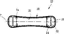
图1是本实用新型第一较佳实施例的正视图;Fig. 1 is the front view of the first preferred embodiment of the utility model;
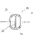
图2是图1沿2-2方向的剖视图;Fig. 2 is a sectional view along the direction 2-2 of Fig. 1;
图3是图1沿3-3方向的剖视图;Fig. 3 is a sectional view along the direction 3-3 of Fig. 1;
图4本实用新型第二较佳实施例的剖视图;Fig. 4 is a sectional view of the second preferred embodiment of the utility model;
图5本实用新型第三较佳实施例的剖视图;Fig. 5 is a sectional view of the third preferred embodiment of the utility model;
图6本实用新型第四较佳实施例的剖视图;Fig. 6 is a sectional view of the fourth preferred embodiment of the utility model;
图7本实用新型第五较佳实施例的剖视图。Fig. 7 is a sectional view of the fifth preferred embodiment of the utility model.
具体实施方式Detailed ways
请参阅图1至图3,本实用新型第一较佳实施例所提供的自行车的后车架10是包含有二长管20与一连接部30,该后车架10可为后叉或下叉,用以连接自行车的座管与后轮。Referring to Fig. 1 to Fig. 3, the
该二长管20是由纤维补强树脂制成,纤维可采用而不限于碳纤维、玻璃纤维、硼纤维或克维拉(Kevlar)纤维,树脂可为热固性树脂或热塑性树脂,该二长管20大致上位于同一平面P,各该长管20内分别具有一肋板22,该长管20内部被该肋板22分成二容室24,该肋板22约垂直于该平面P。The two
该连接部30则接设于该二长管20之间,用以将该二长管20连接在一起,该连接部30是一由纤维补强树脂制成的管体,实际制造时,是先将二长管20硬化成型,接着利用预浸树脂的纤维织布卷绕成一管状的连接件32,将该连接件32置于二长管20之间,接着利用一预浸树脂的纤维织布34将该连接件32与该二长管20包覆起来,再加热硬化成型,即可于该二长管20之间形成该连接部30。The connecting
由该肋板22可大幅增加该长管20的机械强度,使该长管20可承受更大的外力,特别是来自垂直该平面P的外力,因此,无须增加纤维补强树脂的用量,即可加强后车架10整体结构的机械强度,或者,使用较少的材料即可达到所需的结构强度,使本实用新型提供的后车架10兼具机械强度高与重量轻的优点,可改善已知结构的缺点,并达成本实用新型的目的。The
基于本实用新型的精神,该肋板22的形状具有多种变化方式,如图4所示,是本实用新型第二较佳实施例所提供的后车架40,其长管42中具有一肋板44,该肋板44是约平行于二长管42所在的平面P,由此,该长管42的结构强度可大幅提高而可承受更大的外力,特别是来自平行于该平面P的外力。Based on the spirit of the utility model, the shape of the
又如图5所示,是本实用新型第三较佳实施例所提供的后车架50,其长管52中具有三肋板54分别由该长管52的内壁向内延伸而出并汇聚于一线L,该长管52内部被该等肋板54分成三容室56,由此,可均匀提升该长管52各方向的结构强度。As shown in Fig. 5, it is the rear frame 50 provided by the third preferred embodiment of the present invention, and its long tube 52 has three ribs 54 extending inwardly from the inner wall of the long tube 52 and converging On the line L, the inside of the long tube 52 is divided into three chambers 56 by the ribs 54 , thus, the structural strength of the long tube 52 in all directions can be evenly improved.
复如图6所示,是本实用新型第四较佳实施例所提供的后车架60,其长管62中具有四肋板64分别由该长管62的内壁向内延伸而出并汇聚于一线L,该长管62内部被该等肋板64分成四容室66,由此,可更均匀地提升该长管62各方向的结构强度。As shown in Figure 6, it is the
除此之外,连接部的结构与制法亦有多种变化的可能,如图7所示,本实用新型第五较佳实施例所提供的后车架70,具有二长管72与一连接部74,其制法是先将二长管72硬化成型,接着于该二长管72之间置放一发泡心材制成的连接件76,再利用一预浸树脂的纤维织布78将该连接件76与该二长管72包覆起来,该预浸树脂的纤维织布78即形成一管体79,加热硬化成型后即可于该二长管72之间形成该连接部74。In addition, the structure and manufacturing method of the connecting portion also have the possibility of many changes, as shown in Figure 7, the
凡是此等易于思及的结构变化,均应为本实用新型申请专利范围所涵盖。All these structural changes that are easy to think about should be covered by the patent scope of the utility model.
Claims (8)
Translated fromChinesePriority Applications (1)
| Application Number | Priority Date | Filing Date | Title |
|---|---|---|---|
| CNU2007201516408UCN201080232Y (en) | 2007-06-19 | 2007-06-19 | Rear frame of bicycle |
Applications Claiming Priority (1)
| Application Number | Priority Date | Filing Date | Title |
|---|---|---|---|
| CNU2007201516408UCN201080232Y (en) | 2007-06-19 | 2007-06-19 | Rear frame of bicycle |
Publications (1)
| Publication Number | Publication Date |
|---|---|
| CN201080232Ytrue CN201080232Y (en) | 2008-07-02 |
Family
ID=39613911
Family Applications (1)
| Application Number | Title | Priority Date | Filing Date |
|---|---|---|---|
| CNU2007201516408UExpired - Fee RelatedCN201080232Y (en) | 2007-06-19 | 2007-06-19 | Rear frame of bicycle |
Country Status (1)
| Country | Link |
|---|---|
| CN (1) | CN201080232Y (en) |
Cited By (4)
| Publication number | Priority date | Publication date | Assignee | Title |
|---|---|---|---|---|
| CN103930342A (en)* | 2012-10-18 | 2014-07-16 | I.G.纸板技术有限公司 | Structural element comprising cardboard |
| TWI483865B (en)* | 2013-01-29 | 2015-05-11 | ||
| US9598134B2 (en) | 2013-05-02 | 2017-03-21 | I.G. Cardboard Technologies Ltd. | Cardboard-based unit |
| US9656715B2 (en) | 2013-03-15 | 2017-05-23 | I.G. Cardboard Technologies Ltd. | Cardboard-based structure |
- 2007
- 2007-06-19CNCNU2007201516408Upatent/CN201080232Y/ennot_activeExpired - Fee Related
Cited By (9)
| Publication number | Priority date | Publication date | Assignee | Title |
|---|---|---|---|---|
| CN103930342A (en)* | 2012-10-18 | 2014-07-16 | I.G.纸板技术有限公司 | Structural element comprising cardboard |
| US9457535B2 (en) | 2012-10-18 | 2016-10-04 | I.G. Cardboard Technologies Ltd. | Structural element comprising cardboard |
| US9463839B2 (en) | 2012-10-18 | 2016-10-11 | I.G. Cardboard Technologies Ltd. | Structural element comprising cardboard |
| CN103930342B (en)* | 2012-10-18 | 2017-08-22 | I.G.纸板技术有限公司 | Structural detail including cardboard |
| TWI483865B (en)* | 2013-01-29 | 2015-05-11 | ||
| US9656715B2 (en) | 2013-03-15 | 2017-05-23 | I.G. Cardboard Technologies Ltd. | Cardboard-based structure |
| US9598134B2 (en) | 2013-05-02 | 2017-03-21 | I.G. Cardboard Technologies Ltd. | Cardboard-based unit |
| US9616636B2 (en) | 2013-05-02 | 2017-04-11 | I.G. Cardboard Technologies Ltd. | Cardboard-based unit |
| US9688341B2 (en) | 2013-05-02 | 2017-06-27 | I.G. Cardboard Technologies Ltd. | Cardboard-based unit |
Similar Documents
| Publication | Publication Date | Title |
|---|---|---|
| JP3130872U (en) | Bicycle front frame | |
| US7413207B2 (en) | Front fork for a bicycle | |
| US5368804A (en) | Method of molding composite bicycle frames | |
| CN104401011B (en) | Sandwich structure composite material and preparation method thereof | |
| CN201080232Y (en) | Rear frame of bicycle | |
| CN104454944A (en) | Ribbed woven winding carbon fiber composite transmission shaft | |
| CN106273537A (en) | A kind of telescopic joint method and product | |
| EP2740657A1 (en) | Shock-absorbable bicycle frame and method of manufacturing the same | |
| TWM324023U (en) | Rear frame of a bicycle | |
| CN2928662Y (en) | front frame for bicycle | |
| KR101337593B1 (en) | Bicycle frame haing the carbon fiber and the packed layer | |
| CN201872873U (en) | Front fork for bicycle | |
| JPH06114876A (en) | Bicycle frame made of composite material and its manufacture | |
| CN201154747Y (en) | front triangle frame of bicycle | |
| CN202953121U (en) | shock absorbing bicycle frame | |
| CN201183581Y (en) | Shock-absorbing front fork base of bicycle | |
| CN201169349Y (en) | handle structure | |
| CN208962535U (en) | A kind of ply angles of large scale wind power machine root of blade | |
| JP3135363U (en) | Bicycle rear frame | |
| CN202243879U (en) | Multi-layer frame of bicycle | |
| TWM600723U (en) | Composite crank | |
| US20100199498A1 (en) | Process of making base of shock-absorbing front fork for bicycle | |
| CN204785136U (en) | FRP (Fiber reinforced plastics) pipeline | |
| CN209000396U (en) | A kind of guideboard | |
| CN201268352Y (en) | Pipe reinforcement structure |
Legal Events
| Date | Code | Title | Description |
|---|---|---|---|
| C14 | Grant of patent or utility model | ||
| GR01 | Patent grant | ||
| CF01 | Termination of patent right due to non-payment of annual fee | Granted publication date:20080702 Termination date:20140619 | |
| EXPY | Termination of patent right or utility model |