CN201044808Y - Rehabilitation trainer - Google Patents
Rehabilitation trainerDownload PDFInfo
- Publication number
- CN201044808Y CN201044808YCNU2006201725165UCN200620172516UCN201044808YCN 201044808 YCN201044808 YCN 201044808YCN U2006201725165 UCNU2006201725165 UCN U2006201725165UCN 200620172516 UCN200620172516 UCN 200620172516UCN 201044808 YCN201044808 YCN 201044808Y
- Authority
- CN
- China
- Prior art keywords
- utility
- slider
- model
- driver
- arm
- Prior art date
- Legal status (The legal status is an assumption and is not a legal conclusion. Google has not performed a legal analysis and makes no representation as to the accuracy of the status listed.)
- Expired - Fee Related
Links
- 230000007246mechanismEffects0.000claimsabstractdescription22
- 244000309466calfSpecies0.000claimsdescription25
- 210000000689upper legAnatomy0.000claimsdescription22
- 210000003414extremityAnatomy0.000claimsdescription18
- 210000000245forearmAnatomy0.000claimsdescription17
- 230000008093supporting effectEffects0.000claimsdescription17
- 230000005540biological transmissionEffects0.000claimsdescription8
- 230000033001locomotionEffects0.000abstractdescription30
- 238000011084recoveryMethods0.000abstract1
- 238000000034methodMethods0.000description11
- 238000010586diagramMethods0.000description9
- 210000002414legAnatomy0.000description8
- 230000008569processEffects0.000description8
- 230000008859changeEffects0.000description3
- 210000003127kneeAnatomy0.000description2
- 238000005452bendingMethods0.000description1
- 230000037396body weightEffects0.000description1
- 239000003990capacitorSubstances0.000description1
- 230000000694effectsEffects0.000description1
- 239000013013elastic materialSubstances0.000description1
- 238000009434installationMethods0.000description1
- 230000037081physical activityEffects0.000description1
Images


Landscapes
- Rehabilitation Tools (AREA)
Abstract
Description
Translated fromChinese技术领域technical field
本实用新型涉及一种个人使用的康复训练器。The utility model relates to a rehabilitation training device for personal use.
背景技术Background technique
为了帮助肢体活动不便的人们,尤其是帮助偏瘫病人康复,市面上已出现了一些康复训练器。现有产品中,有些虽然可以实现肢体的康复与训练,但必须有专人帮助,使得治疗费用大大增加;或者结构非常复杂,因而品体大笨重价格昂贵,不适于推广使用;或者结构简单,但产生的被动运动轨迹不能贴和人体运动规律,达不到康复训练的目的。而且市面上的功能单一,或者只能锻炼手臂,或者只能锻炼腿部,也增加了复健训练的成本。提供平价高效的康复训练器,是医学应用领域亟待解决的现实需要。In order to help people with inconvenient physical activities, especially to help hemiplegic patients recover, some rehabilitation trainers have appeared on the market. Although some of the existing products can achieve limb rehabilitation and training, they must be helped by special personnel, which greatly increases the cost of treatment; or the structure is very complicated, so the product is bulky and expensive, and is not suitable for popularization; or the structure is simple, but The generated passive motion trajectory cannot fit the law of human motion, and the purpose of rehabilitation training cannot be achieved. Moreover, the functions on the market are single, or they can only exercise the arms, or can only exercise the legs, which also increases the cost of rehabilitation training. It is a practical need to be urgently solved in the field of medical applications to provide affordable and efficient rehabilitation trainers.
实用新型内容Utility model content
本实用新型的目的在于提供能够以简单结构提供合理被动运动轨迹的康复训练器。The purpose of the utility model is to provide a rehabilitation trainer capable of providing a reasonable passive motion trajectory with a simple structure.
为实现本实用新型所述目的,本发明提供一种康复训练器,设置驱动部分和肢体支承设备,驱动部分包括驱动器、底座和底座内的导轨滑块结构,驱动器的动力输出到可沿导轨移动的滑块,滑块与肢体支承设备之间采用铰链连杆机构连接。In order to achieve the purpose of the utility model, the present invention provides a rehabilitation training device, which is provided with a driving part and a limb supporting device. The driving part includes a driver, a base and a guide rail slider structure in the base, and the power output of the driver can move along the guide rail. The slider is connected with the limb supporting device by a hinge linkage mechanism.
而且,所述肢体支承设备为小腿小臂支承器,所述铰链连杆机构采用支条,小腿小臂支承器一端轴接在底座上,另一端与支条之间铰连。Moreover, the limb supporting device is a calf arm supporter, and the hinge link mechanism adopts a support bar. One end of the calf arm supporter is pivotally connected to the base, and the other end is hinged to the support bar.
而且,所述肢体支承设备由联动的小腿小臂支承器和大腿大臂支承器构成,所述铰链连杆机构包括与大腿大臂支承器铰连的上支条和与小腿小臂支承器铰连的下支条,滑块结构的滑块与下支条之间铰连,上支条与底座轴接。Moreover, the limb supporting device is composed of a linked calf and arm support and a thigh and upper arm support, and the hinge linkage mechanism includes an upper support bar hinged with the thigh and arm support and a hinged joint with the calf and forearm support. The connected lower support bar is hinged between the slider of the slider structure and the lower support bar, and the upper support bar is pivotally connected to the base.
而且,小腿小臂支承器和大腿大臂支承器采用四连杆机构。Moreover, the calf and forearm support and the thigh and upper arm support adopt a four-bar linkage mechanism.
而且,将驱动器的动力输出到滑块的传动元件采用丝杠螺母组,丝杠螺母组包括丝杠和丝杠上的传动螺母,丝杆沿导轨设置,传动螺母与滑块连接,驱动器输出接入丝杠。Moreover, the transmission element that outputs the power of the driver to the slider adopts a lead screw nut group. The lead screw nut group includes a lead screw and a drive nut on the lead screw. The lead screw is arranged along the guide rail. The drive nut is connected with the slider. Insert the screw.
而且,驱动器采用可调速控制电机。Moreover, the drive uses an adjustable speed control motor.
本实用新型结构简单,产生的被动运动轨迹贴和人体运动规律,而且功能齐全,既能够锻炼手臂,又能够锻炼腿部,既可以锻炼整条手臂或腿部,也能够根据需要专门锻炼小臂或小腿,病人可根据自己的情况自主地进行康复与训练。因此本实用新型具有携带方便、价格合理、应用广泛等特点,足以满足家庭个人使用,在公共医疗也有很大的推广价值。The utility model has a simple structure, and the generated passive motion track conforms to the law of human body motion, and has complete functions. It can not only exercise the arms, but also exercise the legs, not only the whole arm or leg, but also the forearm according to the needs. Or calf, patients can independently carry out rehabilitation and training according to their own conditions. Therefore, the utility model has the characteristics of convenient portability, reasonable price, wide application, etc., which is enough for family and personal use, and also has great promotion value in public medical care.
附图说明Description of drawings
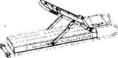
图1是本实用新型实施例一的结构图;Fig. 1 is the structural diagram of the utility model embodiment one;
图2是本实用新型实施例一的正视图;Fig. 2 is the front view of the utility model embodiment one;
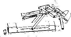
图3是本实用新型实施例二的结构图;Fig. 3 is the structural diagram of the second embodiment of the utility model;
图4是本实用新型实施例二的肢体支承设备结构图;Fig. 4 is a structural diagram of the limb supporting device of the second embodiment of the utility model;
图5A是本实用新型实施例二滑块滑到右极限位置的运动过程简图;Fig. 5A is a schematic diagram of the movement process of the sliding block sliding to the right limit position in the second embodiment of the utility model;
图5B是本实用新型实施例二滑块运动中的运动过程简图;Fig. 5B is a schematic diagram of the movement process in the second embodiment of the utility model during the movement of the slider;
图5C是本实用新型实施例二滑块滑到左极限位置的运动过程简图;Fig. 5C is a schematic diagram of the movement process of the slider sliding to the left limit position in the second embodiment of the utility model;
图6是本实用新型实施例一的运动过程简图。Fig. 6 is a schematic diagram of the movement process of the first embodiment of the utility model.
具体实施方式Detailed ways
参见说明书附图,本实用新型提供一种康复训练器,设置驱动部分和肢体支承设备,驱动部分包括驱动器、底座a1和底座a1内的导轨滑块结构,驱动器的动力输出到可沿导轨移动的滑块a2,导轨滑块结构的滑块a2与肢体支承设备之间采用铰链连杆机构连接。通过导轨滑块结构转换驱动力,再利用导轨和铰链连杆结构,产生贴和人体运动规律的被动运动轨迹。Referring to the drawings in the description, the utility model provides a rehabilitation training device, which is provided with a driving part and a limb support device. The driving part includes a driver, a base a1 and a guide rail slider structure in the base a1. The slider a2, the slider a2 of the guide rail slider structure and the limb support equipment are connected by a hinge linkage mechanism. The driving force is converted through the guide rail slider structure, and then the guide rail and hinge link structure is used to generate a passive motion trajectory that conforms to the law of human motion.
本实用新型提供两种肢体支承设备:一种为锻炼小腿或小臂设计,肢体支承设备为小腿小臂支承器b2,所述铰链连杆机构采用支条b1,小腿小臂支承器b2一端轴接在底座a1上,另一端与支条b1之间铰连;一种为锻炼整个腿部或手臂而设计,由联动的小腿小臂支承器c2和大腿大臂支承器c1构成,所述铰链连杆机构包括与大腿大臂支承器c1铰连的上支条c3和与小腿小臂支承器c2铰连的下支条c4,滑块结构的滑块a2与下支条c4之间铰连,上支条c3与底座a1轴接。具体实施时,生产厂家可以在一套康复训练器中同时提供小腿小臂支承器b2和已连接好的小腿小臂支承器c2和大腿大臂支承器c1,使用时根据需要选用并连接到复健支持设备即可。The utility model provides two kinds of limb supporting devices: one is designed for exercising the calf or the forearm, the limb supporting device is the calf arm support b2, the hinge linkage mechanism adopts the support bar b1, and the calf forearm support b2 has one end shaft It is connected to the base a1, and the other end is hinged with the support bar b1; one is designed for exercising the whole leg or arm, and is composed of the linked calf and arm support c2 and the thigh and upper arm support c1, the hinge The linkage mechanism includes the upper support bar c3 hinged with the thigh arm support c1 and the lower support bar c4 hinged with the lower leg forearm support c2, and the slider a2 of the slider structure is hinged with the lower support bar c4 , the upper branch c3 is connected with the base a1. During specific implementation, the manufacturer can provide the calf and forearm support b2 and the connected calf and forearm support c2 and the thigh and upper arm support c1 in a set of rehabilitation training equipment at the same time. Just support the device.
本实用新型提供的第一种实施方案,将曲柄滑块机构巧妙应用于康复训练,而且能够产生恰当的小臂/小腿运动轨迹。参见附图1、2提供的实施例一,这种结构适合锻炼小臂。除小腿小臂支承器b2可以用来固定小臂外,还设计了托住大臂的大臂托接器b3。滑块a2的平动通过支条b1铰动传递到小腿小臂支承器b2,推动它绕轴转动,从而实现上了小臂的康复与训练。具体实施时,小腿小臂支承器b2的固定肢体部位可使用弹性材料,以适应肢体尺寸变化。当用于小臂训练时,可以添设能够移动的手柄b4供握捏,适应不同的手臂长度。这种结构稍加变化,将底座竖立使用,不设大臂托接器b3,手柄b4作为脚踏使用,便适合于以坐姿锻炼小腿。In the first embodiment provided by the utility model, the slider crank mechanism is skillfully applied to rehabilitation training, and can generate an appropriate movement track of the forearm/calf. Referring to
本实用新型提供的第二种实施方案是曲柄滑块机构和多连杆结构的巧妙组合,能够产生恰当的腿部/手臂运动轨迹。参见附图3、4提供的实施例二,这种结构适合锻炼整个腿部,这种情况下小腿小臂支承器c2需要结合大腿大臂支承器c1设计,可以采用简单的二连杆铰接结构实现,本实用新型实施例二的大腿连接部位和小腿连接部位分别设置在铰接的一对上连杆1和一对下连杆2之间。本实用新型为了能够提供使用者自行施力锻炼的功能,将上连杆1和下连杆2作为杠杆使用,在上连杆1上设置手部施力端(图3中的拉环5或图4中的手柄5′),当不使用驱动器时,使用者在手部施力端使力,上连杆1另一端的大腿连接部位会给使用者相反方向的力,达到多重锻炼目的。同样这种结构稍加变化,设计为可调整尺寸,即可用于锻炼整个手臂。The second embodiment provided by the utility model is an ingenious combination of a slider crank mechanism and a multi-link structure, which can generate proper leg/arm motion tracks. Refer to the second embodiment provided in Figures 3 and 4. This structure is suitable for exercising the entire leg. In this case, the calf and arm support c2 needs to be designed in conjunction with the thigh and arm support c1, and a simple two-link hinge structure can be used To achieve this, the thigh connecting portion and the lower leg connecting portion of the second embodiment of the utility model are respectively arranged between a pair of hinged
为了加强对大腿的支撑作用,实施例二采用四连杆机构实现小腿小臂支承器c2和大腿大臂支承器c1。本实用新型实施例二在上连杆1和下连杆2上基础上,添设了与上连杆1铰接的第一辅助连杆3和与下连杆2铰接的第二辅助连杆4,第一辅助连杆3、第二辅助连杆4与上连杆1、下连杆2共同构成了四连杆机构。四连杆机构同样起杠杆作用,而且当使用者用手在手部施力端向下施力时,第一辅助连杆3对大腿也有支撑力,减轻了大腿连接部位对大腿的支撑负担,令使用者感觉更为舒适。In order to strengthen the supporting effect on the thigh, the second embodiment adopts a four-bar linkage mechanism to realize the calf and arm support c2 and the thigh and arm support c1. In the second embodiment of the utility model, on the basis of the
本实用新型还提供了一系列细部改进以提高实用性能:设置支撑组件,包括底座a1下的支撑长管7、连接在支撑长管7两端的滚轮6和伸缩管8,上支条c3一端与上连杆1固接、另一端与伸缩管8轴连。支撑组件中的伸缩管8,通过调节可以伸缩管8的长度,以适应不同的大腿或手臂长度。滚轮6可以帮助使用者携带,作用近似行李箱底部的滚轮。在底座a1下设置支撑长管7可以便于安装滚轮6和伸缩管8,而且能起一定支撑作用,用者在锻炼时,可以将康复训练器搁置在地面或床上,即可进行康复训练。当适用于不同训练方式时,伸缩管8的设置可根据人体形态适当调整。The utility model also provides a series of detail improvements to improve the practical performance: a supporting assembly is provided, including a supporting long tube 7 under the base a1, rollers 6 and telescopic tubes 8 connected to the two ends of the supporting long tube 7, and one end of the upper branch c3 is connected to the The upper connecting
为了提供复健支持动力,本实用新型将驱动器的动力输出到滑块a2的传动元件采用丝杠螺母组,丝杠螺母组包括丝杠和丝杠上的传动螺母,丝杆沿导轨设置,传动螺母与滑块a2连接,电机输出接入丝杠。具体实施时可采用电机作为驱动器,电机输出轴通过变速机构与丝杆相连,将动力传递给丝杆。丝杠应当与底座a1内的导轨(图3中a3处示意)平行,可设有2根导杆分布在丝杠两边,丝杆的两端通过一对角接触球轴承连接到底座a1两端,并固定。丝杆上装有传动螺母,可将丝杆的转动变为传动螺母的来回平动,传动螺母通过螺母与滑块a2固定,并能带动滑块a2沿导轨来回移动。滑块a2的移动则带动支条b1或下支条c4的移动,带动人的肢体做出相应动作,用以肢体关节活动。In order to provide rehabilitation support power, the utility model uses a screw nut set to output the power of the driver to the transmission element of the slider a2. The screw nut set includes the lead screw and the drive nut on the lead screw. The lead screw is arranged along the guide rail. The nut is connected with the slider a2, and the output of the motor is connected to the lead screw. During specific implementation, a motor can be used as a driver, and the output shaft of the motor is connected with the screw mandrel through a speed change mechanism, and the power is transmitted to the screw mandrel. The screw should be parallel to the guide rail in the base a1 (shown at a3 in Figure 3), and two guide rods can be arranged on both sides of the screw, and the two ends of the screw are connected to the two ends of the base a1 through a pair of angular contact ball bearings , and fixed. The screw rod is equipped with a transmission nut, which can change the rotation of the screw rod into the back and forth translation of the transmission nut. The transmission nut is fixed with the slider a2 through the nut, and can drive the slider a2 to move back and forth along the guide rail. The movement of the slider a2 drives the movement of the branch b1 or the lower branch c4, which drives the human limbs to make corresponding movements for the movement of limb joints.
为了满足不同的锻炼需求,采用可调速控制电机提供不同的锻炼强度。根据人的体重及机构的运动与受力分析可计算出电机的功率范围。由于产品主要用于普通家庭,且需要的电动机功率也不大,同时电机也应该能实现正反转、便于调速,可选择单相异步电动机,查询机械手册上有关电机的内容可选择YY系列单相电容运转异步电动机,额定功率为:90W,额定转速为:3000(r/min)。In order to meet different exercise needs, an adjustable speed control motor is used to provide different exercise intensities. The power range of the motor can be calculated according to the body weight of the person and the movement and force analysis of the mechanism. Since the product is mainly used in ordinary households, and the motor power required is not large, and the motor should also be able to realize forward and reverse rotation, and facilitate speed regulation, a single-phase asynchronous motor can be selected, and the YY series can be selected for the relevant motor content in the mechanical manual. Single-phase capacitor run asynchronous motor, rated power: 90W, rated speed: 3000 (r/min).
为了说明本实用新型的实施效果,本实用新型提供了实施例二的运动过程简图,图5A、图5B和图5C分别表示滑块a2滑到右极限位置、滑块a2运动中(设行程为450)、滑块a2滑到左极限位置。如图5A所示,对应于实施例二的运动形式,AB段表示底座a1内导轨长度,导轨确定了滑块a2滑动的左右极限位置。设AB=450,C点表示上连杆1与伸缩管8的连接处,故AC长度可改变,分析时取AC=166,CD、FM标记上连杆1和下连杆2(CD=230,FM=300),M标记滑块a2,DE标记上支条c3,EF标记下支条c4(D、F处是固定铰接,DE=100,EF=160)。此实施例作康复锻炼运动时,主要机构是一个曲柄滑块机构,图5A、图5B和图5C中用一个小方块的移动代表由于滑块a2及驱动机构带来的E点位置变动。由于大腿结构已确定(弯角已知),故CE、EM长度可以计算出来,CE=313,EM=434。电动机驱动滑块a2在行程AB来回运动使连杆CE、EM运动从而带动大、小腿做相关伸屈运动。当滑块a2运动到行程A、B两端时可计算出运动范围,例如附图中标注的各角度。如附图5B、5C,可以得出计算结果(或者用AUTO CAD等软件直接得出结果,计算过程略),可见本实用新型使用于腿部时人体运动范围很大:In order to illustrate the implementation effect of the present utility model, the utility model provides a schematic diagram of the motion process of
膝:20°~170° (以膝盖为顶点,大、小腿为边)Knee: 20°~170° (with the knee as the vertex, the thigh and calf as the sides)
髋:10°~110° (以大腿根步与地面的交点为顶点,大腿、地面为边)Hip: 10°~110° (take the intersection point of the thigh root step and the ground as the vertex, and the thigh and the ground as the sides)
实施例一的结构较为简单,运动过程简图参见图6,是实施例二运动关系的简化,A′、B′、C′分别相应于图5A、图5B和图5C中的A、C、E点。其他使用方法的运动过程均与本实用新型提供的实施例类似,本实用新型不予赘述。The structure of
Claims (7)
Translated fromChinesePriority Applications (1)
| Application Number | Priority Date | Filing Date | Title |
|---|---|---|---|
| CNU2006201725165UCN201044808Y (en) | 2006-12-22 | 2006-12-22 | Rehabilitation trainer |
Applications Claiming Priority (1)
| Application Number | Priority Date | Filing Date | Title |
|---|---|---|---|
| CNU2006201725165UCN201044808Y (en) | 2006-12-22 | 2006-12-22 | Rehabilitation trainer |
Publications (1)
| Publication Number | Publication Date |
|---|---|
| CN201044808Ytrue CN201044808Y (en) | 2008-04-09 |
Family
ID=39308282
Family Applications (1)
| Application Number | Title | Priority Date | Filing Date |
|---|---|---|---|
| CNU2006201725165UExpired - Fee RelatedCN201044808Y (en) | 2006-12-22 | 2006-12-22 | Rehabilitation trainer |
Country Status (1)
| Country | Link |
|---|---|
| CN (1) | CN201044808Y (en) |
Cited By (8)
| Publication number | Priority date | Publication date | Assignee | Title |
|---|---|---|---|---|
| CN102614063A (en)* | 2012-04-10 | 2012-08-01 | 芜湖天人智能机械有限公司 | Support-movable and amplitude-adjustable training device for rehabilitation of upper and lower limbs |
| CN103316446A (en)* | 2013-07-12 | 2013-09-25 | 芜湖天人智能机械有限公司 | Rail-variable upper limb and lower limb coordinated exercise training mechanism with moving pair |
| CN105078705A (en)* | 2015-08-25 | 2015-11-25 | 广西大学 | Thread screw type physiotherapy apparatus capable of relieving rigidity of muscles and activating collaterals for legs |
| CN105326624A (en)* | 2014-08-14 | 2016-02-17 | 北京信息科技大学 | Rehabilitation training auxiliary equipment for spatial motion of upper/lower limbs |
| CN105879322A (en)* | 2016-04-05 | 2016-08-24 | 许昌学院 | Aerobics teaching device |
| CN105920782A (en)* | 2016-04-13 | 2016-09-07 | 许昌学院 | Fixed type comprehensive sport system |
| CN111569369A (en)* | 2020-05-18 | 2020-08-25 | 武汉尚诚源健康科技有限公司 | Olecranal fracture postoperative exercise device |
| CN112569542A (en)* | 2020-12-09 | 2021-03-30 | 湖南泰贵生物科技有限公司 | Surgical rehabilitation nursing moving device |
- 2006
- 2006-12-22CNCNU2006201725165Upatent/CN201044808Y/ennot_activeExpired - Fee Related
Cited By (10)
| Publication number | Priority date | Publication date | Assignee | Title |
|---|---|---|---|---|
| CN102614063A (en)* | 2012-04-10 | 2012-08-01 | 芜湖天人智能机械有限公司 | Support-movable and amplitude-adjustable training device for rehabilitation of upper and lower limbs |
| CN103316446A (en)* | 2013-07-12 | 2013-09-25 | 芜湖天人智能机械有限公司 | Rail-variable upper limb and lower limb coordinated exercise training mechanism with moving pair |
| CN103316446B (en)* | 2013-07-12 | 2015-04-22 | 芜湖天人智能机械有限公司 | Rail-variable upper limb and lower limb coordinated exercise training mechanism with moving pair |
| CN105326624A (en)* | 2014-08-14 | 2016-02-17 | 北京信息科技大学 | Rehabilitation training auxiliary equipment for spatial motion of upper/lower limbs |
| CN105326624B (en)* | 2014-08-14 | 2017-07-07 | 北京信息科技大学 | Upper limbs/lower limb spatial movement rehabilitation training auxiliary equipment |
| CN105078705A (en)* | 2015-08-25 | 2015-11-25 | 广西大学 | Thread screw type physiotherapy apparatus capable of relieving rigidity of muscles and activating collaterals for legs |
| CN105879322A (en)* | 2016-04-05 | 2016-08-24 | 许昌学院 | Aerobics teaching device |
| CN105920782A (en)* | 2016-04-13 | 2016-09-07 | 许昌学院 | Fixed type comprehensive sport system |
| CN111569369A (en)* | 2020-05-18 | 2020-08-25 | 武汉尚诚源健康科技有限公司 | Olecranal fracture postoperative exercise device |
| CN112569542A (en)* | 2020-12-09 | 2021-03-30 | 湖南泰贵生物科技有限公司 | Surgical rehabilitation nursing moving device |
Similar Documents
| Publication | Publication Date | Title |
|---|---|---|
| CN201044808Y (en) | Rehabilitation trainer | |
| CN104905938B (en) | A horizontal upper and lower limb rehabilitation training device | |
| CN103462780B (en) | Foldable, variable track upper and lower limb coordination exercise training chair | |
| CN202437606U (en) | Lower extremity rehabilitation training device | |
| CN202776920U (en) | Power-assist training device for lower limb rehabilitation | |
| CN206304093U (en) | A kind of lower limb power-assisted and trainer | |
| CN105943308A (en) | Hand exoskeleton device for rehabilitation training | |
| CN205814618U (en) | A kind of multi-state upper-limbs rehabilitation training robot | |
| CN108814898B (en) | A hand function rehabilitation training system | |
| CN105726264B (en) | A kind of healthy image training robot | |
| WO2015003471A1 (en) | Foldable and orbit transferrable upper and lower limb coordination exercise training chair | |
| CN206261792U (en) | A kind of healthy plint of multi-pose lower limb | |
| CN105919776A (en) | Multi-working condition upper limb rehabilitation training robot | |
| CN111759663A (en) | A multi-degree-of-freedom upper limb rehabilitation device | |
| CN102688135B (en) | Upper and lower limb rehabilitation training device with variable rod length | |
| CN108836740A (en) | A kind of multidigit appearance limbs coordination recovery exercising robot | |
| CN204601060U (en) | The bionical device for healing and training of a kind of shoulder joint kinesitherapy | |
| CN108524196A (en) | A kind of hand functional training driving device | |
| CN111658438A (en) | Lower limb rehabilitation training robot | |
| CN205698427U (en) | A kind of healthy image training robot | |
| CN208081471U (en) | A kind of lower limb rehabilitation training device | |
| CN101647736A (en) | Parallel-connection ectoskeleton knee joint | |
| CN106974802B (en) | Multi-rod type lower limb rehabilitation massage trainer | |
| CN113545965A (en) | An exoskeleton robot for assisting lower limb rehabilitation training | |
| CN112022610A (en) | An ankle joint rehabilitation mechanism with adjustable rotation center |
Legal Events
| Date | Code | Title | Description |
|---|---|---|---|
| C14 | Grant of patent or utility model | ||
| GR01 | Patent grant | ||
| C19 | Lapse of patent right due to non-payment of the annual fee | ||
| CF01 | Termination of patent right due to non-payment of annual fee |