CN201043670Y - Support seat structure of computer peripheral device - Google Patents
Support seat structure of computer peripheral deviceDownload PDFInfo
- Publication number
- CN201043670Y CN201043670YCNU2007200031630UCN200720003163UCN201043670YCN 201043670 YCN201043670 YCN 201043670YCN U2007200031630 UCNU2007200031630 UCN U2007200031630UCN 200720003163 UCN200720003163 UCN 200720003163UCN 201043670 YCN201043670 YCN 201043670Y
- Authority
- CN
- China
- Prior art keywords
- clamping
- clamping end
- pivot
- computer peripheral
- arc
- Prior art date
- Legal status (The legal status is an assumption and is not a legal conclusion. Google has not performed a legal analysis and makes no representation as to the accuracy of the status listed.)
- Expired - Fee Related
Links
- 230000002093peripheral effectEffects0.000titleclaimsabstractdescription27
- 239000004973liquid crystal related substanceSubstances0.000description6
- 230000000694effectsEffects0.000description3
- 238000000034methodMethods0.000description3
- 238000004891communicationMethods0.000description2
- 238000010586diagramMethods0.000description2
- 238000004519manufacturing processMethods0.000description2
- 230000006835compressionEffects0.000description1
- 238000007906compressionMethods0.000description1
- 238000013016dampingMethods0.000description1
- 238000005516engineering processMethods0.000description1
- 230000005484gravityEffects0.000description1
- 230000017525heat dissipationEffects0.000description1
- 230000008054signal transmissionEffects0.000description1
- XLYOFNOQVPJJNP-UHFFFAOYSA-NwaterSubstancesOXLYOFNOQVPJJNP-UHFFFAOYSA-N0.000description1
Images


Landscapes
- Devices For Indicating Variable Information By Combining Individual Elements (AREA)
Abstract
Description
Translated fromChinese技术领域technical field
本实用新型涉及一种计算机周边装置的支撑座结构,特别是一种可将计算机影像获取装置固定设置于显示装置上的计算机周边装置的支撑座结构。The utility model relates to a support seat structure of a computer peripheral device, in particular to a support seat structure of a computer peripheral device which can fix a computer image acquisition device on a display device.
背景技术Background technique
近年来软件及网络科技不断地发展进步,再加上与硬件的相互搭配,使得实时影音通讯变得相当普及。以现今最常被使用者使用的网络摄影机(webcam)而言,仅需一台网络摄影机,再通过网际网络的信号传输即可克服地域上的限制,与远方的亲友进行面对面的视讯对话,提供忙碌的使用者一个便利的沟通管道。In recent years, the continuous development and progress of software and network technology, coupled with the mutual matching with hardware, has made real-time audio-visual communication quite popular. Taking the most commonly used webcam (webcam) by users today, only one webcam is needed, and then the signal transmission through the Internet can overcome geographical restrictions, and have face-to-face video conversations with distant relatives and friends, providing A convenient communication channel for busy users.
一般现有的网络摄影机为了配合使用者不同的摆放需求,通常会装设有一支撑装置,以提供使用者可将网络摄影机平放于桌面、摆放或夹持于显示器的边缘。目前所见的显示器种类分为台式计算机用的阴极射线管(Cathode RayTube,CRT)的显示器、液晶显示器(Liquid Crystal Display,LCD)、以及笔记型计算机所使用的平面显示器,尤其是针对笔记型计算机而言,使用者在任何可操作笔记型计算机的地方,并不见得有足够的空间供网络摄影机放置,因此夹持功能对网络摄影机来说,已是不可或缺的重要功能。Generally, in order to meet different placement requirements of users, the existing network cameras are usually equipped with a support device, so that users can place the network cameras flat on the desktop, place them or clamp them on the edge of the display. The types of displays currently seen are divided into cathode ray tube (Cathode Ray Tube, CRT) displays for desktop computers, liquid crystal displays (Liquid Crystal Display, LCD), and flat-panel displays for notebook computers, especially for notebook computers. Generally speaking, there may not be enough space for the network camera to be placed in any place where the user can operate the notebook computer. Therefore, the clamping function is an indispensable and important function for the network camera.
一般而言,台式计算机用的显示器的厚度较厚,其背面也经常设计成曲面形式,以预留较大的内部空间以供散热,而笔记型计算机标榜轻薄,因此所使用的显示器厚度亦远小于台式计算机用的显示器,其形态也呈现前、后侧面相互平行的矩形板体,使得现有的支撑装置无法适用于任何形态的显示器的夹持固定,而产生容易滑落,甚至是无法发挥任何夹持固定效果的问题。因此,网络摄影机的支撑座必须具备弹性宽度调整的夹持设计,以符合应用于任何种类的显示器的需求。Generally speaking, the monitors used in desktop computers are thicker, and their backs are often designed with curved surfaces to reserve a larger internal space for heat dissipation. Notebook computers are advertised as thin and light, so the monitors used are also far thicker. Smaller than the display used for desktop computers, its form also presents a rectangular plate whose front and rear sides are parallel to each other, so that the existing support device cannot be applied to the clamping and fixing of any form of display, and it is easy to slip and fall, and even cannot play any role. Problems with clamping fixation effects. Therefore, the supporting seat of the network camera must have a clamping design with elastic width adjustment, so as to meet the requirements of being applied to any kind of display.
中国台湾专利第372081号专利及第M243870号专利中揭露一种可调整夹持宽度的计算机周边装置的支撑座结构,利用二夹臂互相枢接而形成一夹持空间,由相对枢转以夹持于一平面显示器的边缘,二夹臂间可利用改变夹角的方式,调整夹持厚度,以因应不同厚度的显示器。另外,于中国台湾专利第M299813号专利中揭示一种夹座构造,以一压缩弹簧控制夹持于平面显示器的夹板的夹持宽度,并由扣座抵靠于显示器的背面,以夹持于不同厚度的显示器边缘。China Taiwan Patent No. 372081 and No. M243870 Patent disclose a support seat structure of a computer peripheral device with adjustable clamping width. Two clamping arms are pivotally connected to each other to form a clamping space, which is clamped by relative pivoting. It is held on the edge of a flat-panel display, and the clamping thickness can be adjusted by changing the angle between the two clamping arms to cope with displays of different thicknesses. In addition, a clamp structure is disclosed in Taiwan Patent No. M299813, which uses a compression spring to control the clamping width of the clamp plate clamped on the flat-panel display, and the buckle seat leans against the back of the display to clamp on the Display edges of different thicknesses.
TW372081案所揭露的支撑座针对前、后侧面相互平行的平面显示器进行设计,由于其二夹臂之间设计为互相平行的形态,若是应用于厚度大或是背面为曲面构造的显示器,夹臂必须撑张加大夹角,导致位于显示器前、后侧的两夹臂与显示器之间形成二点接触的形式,如此将无法使支撑座稳定地夹持而容易产生滑落。此外,这种利用夹臂中央作为枢接支点的方式,还造成夹持空间的限制;而加长夹臂尺寸的结果,亦相对地减弱所能施加的夹持力量;而夹(力)臂加长后,一但受到外界轻微的碰触,便很容地会因力矩的增加而丧失较佳的固定能力。若大幅地增加位于中央枢接支点的弹簧的弹力,则使用者开启夹持空间时必须施以极大的开启力量,因此会造成使用上的不便。The supporting seat disclosed in the TW372081 case is designed for a flat-panel display whose front and rear sides are parallel to each other. Since the two clamping arms are designed to be parallel to each other, if it is applied to a display with a large thickness or a curved surface structure on the back, the clamping arm It is necessary to stretch and increase the included angle, resulting in a two-point contact form between the two clamping arms located on the front and rear sides of the display and the display, so that the supporting base cannot be stably clamped and is prone to slipping. In addition, this method of using the center of the clamp arm as the pivotal fulcrum also limits the clamping space; and the result of lengthening the size of the clamp arm also relatively weakens the clamping force that can be applied; and the clamp (force) arm is lengthened Finally, once it is slightly touched by the outside world, it will easily lose its better fixing ability due to the increase of torque. If the elastic force of the spring located at the central pivotal fulcrum is greatly increased, the user must apply a large opening force when opening the clamping space, which will cause inconvenience in use.
TWM372081号案虽具有一枢接座及一挡墙的结构,但该枢接座与挡墙之间仍是一种类似ㄇ字型的传统的夹持方式,且所有的夹持力量皆来自于挡墙后的拉力弹簧,对于不同造型的显示器周沿亦无法提供稳固的夹持。同时,为了容置弹簧及维持正确的弹簧施力方向,复杂的组成结构亦大幅地增加制造与组装的成本。另外,该案也无法置于一工作平面上使用。Although the TWM372081 case has a structure of a pivot seat and a retaining wall, there is still a traditional clamping method similar to a ㄇ shape between the pivot seat and the retaining wall, and all the clamping forces come from The tension spring behind the retaining wall cannot provide stable clamping for the periphery of displays of different shapes. At the same time, in order to accommodate the spring and maintain the correct force direction of the spring, the complex composition structure also greatly increases the cost of manufacturing and assembly. In addition, the case cannot be placed on a work plane for use.
而不论TWM299813或是TW372081号案皆是利用弹簧作为夹持力量的来源,若增加夹持力量亦代表可能会对所夹持的对象或是显示器的周沿面造成损伤,因此又必须增加夹持垫的厚度,从而造成制作成本的增加。Regardless of the TWM299813 or TW372081 case, the spring is used as the source of the clamping force. If the clamping force is increased, it may also cause damage to the clamped object or the peripheral surface of the display. Therefore, it is necessary to increase the clamping pad. thickness, resulting in an increase in production costs.
发明内容Contents of the invention
鉴于以上的问题,本实用新型提供一种计算机周边装置的支撑座结构,以改进现有技术的支撑装置受限于不同显示器的尺寸或是型态,而无法稳固地设置于各类型的显示器上的问题。In view of the above problems, the utility model provides a support base structure for computer peripheral devices to improve the support device in the prior art, which is limited by the size or type of different displays, and cannot be stably installed on various types of displays. The problem.
本实用新型所揭露的计算机周边装置的支撑座结构用以装设计算机影像获取装置,并固定设置于显示装置上。计算机外设装置的支撑座结构包括有一承载件及一座体;The support seat structure of the computer peripheral device disclosed by the utility model is used for installing the computer image acquisition device and is fixedly arranged on the display device. The supporting seat structure of the computer peripheral device includes a bearing part and a base;
其中该承载件具有一第一顶端及一第一夹持端,且该座体具有一第二顶端及一第二夹持端;该第一顶端及该第二顶端之间具有一枢接单元;Wherein the carrier has a first top end and a first clamping end, and the seat body has a second top end and a second clamping end; there is a pivot unit between the first top end and the second top end ;
该枢接单元为一阻力产生装置,并为该第一夹持端与该第二夹持端的共同支点;且该第一夹持端与该第二夹持端之间具有一夹持空间;The pivot unit is a resistance generating device, and is a common fulcrum of the first clamping end and the second clamping end; and there is a clamping space between the first clamping end and the second clamping end;
其中该承载件具有一向下的第一弧形内面,且该底座亦对应具有一向上的第二弧形内面;该第一夹持端位于该第一弧形内面,且该第二夹持端位于该第二弧形内面。Wherein the carrier has a downward first arc-shaped inner surface, and the base also correspondingly has an upward second arc-shaped inner surface; the first clamping end is located on the first arc-shaped inner surface, and the second clamping end Located on the inner surface of the second arc.
上述的计算机外设装置的支撑座结构,其中,该座体与该承载件分别设有相对应的至少一轴耳,且于各该轴耳上设置一枢接孔,并由该枢接单元而使该座体与该承载件相互枢接。In the above-mentioned support base structure for computer peripheral devices, the base body and the bearing member are respectively provided with at least one corresponding axle lug, and a pivot hole is provided on each axle lug, and the pivot joint unit And make the seat body and the bearing part pivot to each other.
上述的计算机外设装置的支撑座结构,其中,该枢接单元为一设置于该枢接孔中的垫圈,且一枢设件穿设过该垫圈并固定于该枢接孔。In the above-mentioned support base structure for computer peripheral devices, the pivot unit is a washer disposed in the pivot hole, and a pivot member passes through the washer and is fixed in the pivot hole.
上述的计算机外设装置的支撑座结构,其中,该第一夹持端还装设有至少一止滑块。In the above-mentioned support base structure for computer peripheral devices, at least one stopper block is installed on the first clamping end.
上述的计算机外设装置的支撑座结构,其中,该第二夹持端还具有一支撑件。In the above-mentioned support base structure for computer peripheral devices, the second clamping end further has a support member.
上述的计算机外设装置的支撑座结构,其中,该承载件还包括有一枢转接头,且该枢转接头凸设于该承载件外的一端接设一计算机影像获取装置。In the above-mentioned support base structure for computer peripheral devices, the bearing part further includes a pivot joint, and one end of the pivot joint protruding outside the bearing part is connected with a computer image acquisition device.
本实用新型的功效在于,支撑座可根据不同型态的显示装置,而调整承载件与座体之间的枢接角度,并由承载件的勾扣部、翼片及座体前端分别勾扣并抵靠于显示装置的前、上、后侧边,以三点支撑的方式稳定地设置于显示装置上。The effect of the utility model is that the supporting seat can adjust the pivot angle between the supporting part and the seat body according to different types of display devices, and the hooking part, the wings and the front end of the seat body are respectively hooked and buckled. And lean against the front, upper, and rear sides of the display device, and be stably arranged on the display device in a three-point support manner.
以下结合附图和具体实施例对本实用新型进行详细描述,但不作为对本实用新型的限定。The utility model will be described in detail below in conjunction with the accompanying drawings and specific embodiments, but not as a limitation of the utility model.
附图说明Description of drawings
图1为本实用新型的分解示意图;Fig. 1 is the exploded schematic view of the utility model;
图2为本实用新型的立体示意图;Fig. 2 is the three-dimensional schematic view of the utility model;
图3A为本实用新型的摆放于平面上的侧视图;Figure 3A is a side view of the utility model placed on a plane;
图3B为本实用新型的设置于液晶显示器上的侧视图;Fig. 3B is a side view of the utility model arranged on the liquid crystal display;
图3C为本实用新型的设置于笔记型计算机的屏幕上的侧视图;以及Figure 3C is a side view of the utility model set on the screen of the notebook computer; and
图3D为本实用新型的设置于阴极射线管显示器上的侧视图。FIG. 3D is a side view of the present invention installed on a cathode ray tube display.
其中,附图标记Among them, reference signs
100支撑座 110座体100
111支撑件 112铅块111
120承载件 121勾扣部120
122翼片 123止滑块122 fins 123 stop slider
124枢转接头 130轴耳124 Pivot Joint 130 Shaft Lug
131枢接孔 140枢接单元131
141垫圈 142枢设件141 Washer 142 Pivot
200计算机影像获取装置 300显示装置200 computer
具体实施方式Detailed ways
下面结合附图对本实用新型的结构原理和工作原理作具体的描述:Below in conjunction with accompanying drawing, structural principle and working principle of the present utility model are specifically described:
根据本实用新型所揭露的计算机周边装置的支撑座结构,与计算机周边装置相互连接,其计算机周边装置包括但不局限于计算机相机(PC camera)、网络摄影机(web cam)...等影像获取装置,或是扬声器、麦克风...等计算机周边装置,而于以下本实用新型的详细说明中,将以网络摄影机做为本实用新型的最佳实施例。然而所附图仅提供参考与说明用,并非用以限制本实用新型。According to the support seat structure of the computer peripheral device disclosed in the utility model, it is connected with the computer peripheral device, and its computer peripheral device includes but not limited to computer camera (PC camera), network camera (web cam)...etc. image acquisition Devices, or computer peripheral devices such as speakers, microphones, etc., and in the following detailed description of the utility model, a network camera will be used as the best embodiment of the utility model. However, the accompanying drawings are provided for reference and illustration only, and are not intended to limit the present invention.
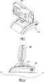
图1及图2所示为本实用新型的立体示意图,本实用新型所揭露的支撑座100结构用以装设一计算机周边装置,比如一计算机影像获取装置200,以将计算机影像获取装置200固定设置于一对象上,比如一显示装置上,例如可为液晶显示器、笔记型计算机的屏幕、阴极射线管显示器等显示装置。本实用新型的支撑座100结构包括有一座体110及一承载件120,其中座体110为一底部为平整面的矩形结构,且于内部设有一容置空间,承载件120具有一夹持端及一顶端,且该座体110亦具有一夹持端及一顶端;该承载件120的顶端及该座体110的顶端以可枢转的关系枢接为一体;该承载件120具有一弧形内面,且该座体亦具有一对应的弧形内面,使得该承载件120的夹持端及该座体110的夹持端分别位于该弧形内面之上。另外,于承载件120的夹持端上设有一勾扣部121,以及分别设置于相对两侧边的翼片122。Fig. 1 and Fig. 2 are three-dimensional schematic diagrams of the present utility model, and the structure of the
如图1及图2所示,座体110与承载件120的枢接端上分别设有相对应的两相对轴耳130,于各个轴耳130上开设有一枢接孔131,并由两枢接单元140而使得座体110与承载件120相互枢接。本实用新型所揭露的枢接单元140为一种阻力产生装置,包括利用油、水所制作出的阻尼产生装置,或是利用紧配合所制作出的阻力产生装置;本实施例利用紧配合的方式作为说明,包括有一垫圈141及一枢设件142,其中垫圈141设置于承载件120的枢接孔131内,而枢设件142为一螺栓,穿设过垫圈141并锁固于座体110的枢接孔131中,使得承载件120得以将枢设件142做为轴心而相对座体110枢转,且垫圈141可提供承载件120一定的摩擦力(即阻力)故而具备定位的效果。As shown in Figures 1 and 2, two corresponding shaft lugs 130 are respectively provided on the pivot joint ends of the
请继续参阅图1,于承载件120的勾扣部121内侧还装设有两止滑块123,并于座体110的前端设置一长条带状的支撑件111,以分别增加勾扣部121与座体110的摩擦阻力。另外,承载件120还具有一枢转接头124,其一端设置于承载件120内,另一端凸设至承载件120外,以与计算机影像获取装置200相连结,使得计算机影像获取装置200由枢转接头124而调整拍摄角度,且座体110内部还装设有一铅块112,可使支撑座100的整体重心下移,以增加其稳定性。Please continue to refer to FIG. 1, two
图3A至图3D为本实用新型的计算机周边装置的支撑座结构摆设于平面上及应用于各类型显示装置上的示意图。FIG. 3A to FIG. 3D are schematic diagrams of the supporting base structure of the computer peripheral device of the present invention arranged on a plane and applied to various types of display devices.
如图3A所示,使用者可选择性地将装设有计算机影像获取装置200的承载件120盖合于座体110的上半部,以使装设有计算机影像获取装置200的支撑座100可稳定地摆放于平面上。As shown in FIG. 3A , the user can selectively cover the
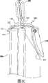
如图3B、图3C及图3D所示,本实用新型的支撑座100还可设置于液晶显示器、笔记型计算机的屏幕、阴极射线管显示器等显示装置300上,当支撑座100应用于液晶显示器或是笔记型计算机的屏幕等厚度较薄的显示装置300时,使用者依照不同厚度尺寸的显示装置300,枢转承载件120以展开适当的角度而形成一夹持空间,并以勾扣部121勾扣于显示装置300的前缘,翼片122抵靠于显示装置300的上缘,而座体110前端抵靠于显示装置300的后缘,使得支撑座100以三点支撑的方式固定于显示装置300上,分别设置于勾扣部121与座体110上的止滑块123与支撑件111将提供一摩擦阻力,而枢接单元140的垫圈141亦提供一固持力,使得座体110与承载件120之间保持固定于最佳的夹持角度,致使支撑座100更稳定地勾设于显示装置300上,而不致脱落;若是将本实用新型的支撑座100应用于体积较大的阴极射线管显示装置300时,承载件120与座体110相互结合,以平稳地将计算机影像获取装置200摆放于阴极射线管显示装置300上缘。As shown in Figure 3B, Figure 3C and Figure 3D, the support base 100 of the present utility model can also be arranged on display devices 300 such as liquid crystal displays, notebook computer screens, cathode ray tube displays, etc., when the support base 100 is applied to liquid crystal displays Or for a display device 300 with a thinner thickness such as a screen of a notebook computer, the user pivots the bearing member 120 to form a clamping space according to the display device 300 of different thickness and size to expand an appropriate angle, and uses the hook part 121 is hooked on the front edge of the display device 300, the wings 122 are against the upper edge of the display device 300, and the front end of the base body 110 is against the rear edge of the display device 300, so that the support base 100 is fixed in a three-point support manner On the display device 300, the anti-sliding block 123 and the support member 111 respectively provided on the hook portion 121 and the base body 110 will provide a frictional resistance, and the washer 141 of the pivot unit 140 also provides a holding force, so that the base body 110 and the carrier 120 are kept fixed at an optimal clamping angle, so that the support base 100 can be hooked on the display device 300 more stably without falling off; if the support base 100 of the present invention is applied to a larger volume When the cathode ray tube display device 300 is used, the supporting member 120 and the base body 110 are combined with each other to place the computer image acquisition device 200 on the upper edge of the cathode ray tube display device 300 smoothly.
本实用新型所揭露的计算机周边装置的支撑座结构,可根据不同尺寸或是型态的显示器,而调整承载件与座体之间的枢转角度,并由垫圈提供一阻力,以使支撑座保持在与显示装置最为贴合的夹持角度,且支撑座通过承载件的勾扣部、翼片、及座体的前端,以与显示装置作三点支撑的稳固架设。The support seat structure of the computer peripheral device disclosed by the utility model can adjust the pivot angle between the bearing part and the seat body according to different sizes or types of displays, and the washer provides a resistance to make the support seat The clamping angle is kept at the best fit with the display device, and the support base is stably erected with the display device as a three-point support through the hook portion of the carrier, the wings, and the front end of the seat body.
当然,本实用新型还可有其它多种实施例,在不背离本实用新型精神及其实质的情况下,熟悉本领域的技术人员当可根据本实用新型作出各种相应的改变和变形,但这些相应的改变和变形都应属于本实用新型所附的权利要求的保护范围。Of course, the utility model can also have other various embodiments, and those skilled in the art can make various corresponding changes and deformations according to the utility model without departing from the spirit and essence of the utility model, but These corresponding changes and deformations should all belong to the protection scope of the appended claims of the present utility model.
Claims (6)
Translated fromChinesePriority Applications (1)
| Application Number | Priority Date | Filing Date | Title |
|---|---|---|---|
| CNU2007200031630UCN201043670Y (en) | 2007-02-02 | 2007-02-02 | Support seat structure of computer peripheral device |
Applications Claiming Priority (1)
| Application Number | Priority Date | Filing Date | Title |
|---|---|---|---|
| CNU2007200031630UCN201043670Y (en) | 2007-02-02 | 2007-02-02 | Support seat structure of computer peripheral device |
Publications (1)
| Publication Number | Publication Date |
|---|---|
| CN201043670Ytrue CN201043670Y (en) | 2008-04-02 |
Family
ID=39258565
Family Applications (1)
| Application Number | Title | Priority Date | Filing Date |
|---|---|---|---|
| CNU2007200031630UExpired - Fee RelatedCN201043670Y (en) | 2007-02-02 | 2007-02-02 | Support seat structure of computer peripheral device |
Country Status (1)
| Country | Link |
|---|---|
| CN (1) | CN201043670Y (en) |
Cited By (1)
| Publication number | Priority date | Publication date | Assignee | Title |
|---|---|---|---|---|
| CN103119349A (en)* | 2010-08-04 | 2013-05-22 | 萨万特系统有限责任公司 | In-wall dock for a tablet computer |
- 2007
- 2007-02-02CNCNU2007200031630Upatent/CN201043670Y/ennot_activeExpired - Fee Related
Cited By (2)
| Publication number | Priority date | Publication date | Assignee | Title |
|---|---|---|---|---|
| CN103119349A (en)* | 2010-08-04 | 2013-05-22 | 萨万特系统有限责任公司 | In-wall dock for a tablet computer |
| CN103119349B (en)* | 2010-08-04 | 2015-05-06 | 萨万特系统有限责任公司 | In-wall dock for tablet |
Similar Documents
| Publication | Publication Date | Title |
|---|---|---|
| US8186639B2 (en) | Bracket for tablet electronic device | |
| TWI221954B (en) | Flat panel display | |
| TWI330313B (en) | ||
| TWM539645U (en) | Hinge for electronic devices | |
| CN201043670Y (en) | Support seat structure of computer peripheral device | |
| CN201110988Y (en) | Support structure | |
| CN203010153U (en) | An adjustable support structure for flat panel TV | |
| CN2922063Y (en) | screen support structure | |
| CN105939406A (en) | Mobile phone with support frame | |
| CN201149670Y (en) | Computer Peripheral Device Structure | |
| CN104141863B (en) | Electronic device and its support mechanism | |
| CN207526868U (en) | Thin hub device | |
| CN207349264U (en) | Thin hub device | |
| CN200989512Y (en) | Network camera foot structure | |
| JP3130296U (en) | Webcam pedestal configuration | |
| CN103375667B (en) | Electronic device holding frame | |
| US11188119B2 (en) | Portable computer peripheral holder | |
| CN217540171U (en) | Support frame | |
| TWI327263B (en) | ||
| CN221402306U (en) | Flat clamp capable of clamping forward and backward and floor stand | |
| CN200941172Y (en) | Computer peripheral device and its supporting seat | |
| CN2795923Y (en) | Support seat for computer peripheral device | |
| CN221958471U (en) | Display mounting rack | |
| CN202660173U (en) | Support frame structure of flat panel display device | |
| CN209278813U (en) | Portable intelligent device hand-held support device |
Legal Events
| Date | Code | Title | Description |
|---|---|---|---|
| C14 | Grant of patent or utility model | ||
| GR01 | Patent grant | ||
| C17 | Cessation of patent right | ||
| CF01 | Termination of patent right due to non-payment of annual fee | Granted publication date:20080402 Termination date:20140202 |