CN200994767Y - A distraction device for minimally invasive lumbar surgery - Google Patents
A distraction device for minimally invasive lumbar surgeryDownload PDFInfo
- Publication number
- CN200994767Y CN200994767YCN 200720002115CN200720002115UCN200994767YCN 200994767 YCN200994767 YCN 200994767YCN 200720002115CN200720002115CN 200720002115CN 200720002115 UCN200720002115 UCN 200720002115UCN 200994767 YCN200994767 YCN 200994767Y
- Authority
- CN
- China
- Prior art keywords
- minimally invasive
- invasive lumbar
- distraction device
- bracket
- lumbar surgery
- Prior art date
- Legal status (The legal status is an assumption and is not a legal conclusion. Google has not performed a legal analysis and makes no representation as to the accuracy of the status listed.)
- Expired - Lifetime
Links
- 238000001356surgical procedureMethods0.000titleclaimsabstractdescription36
- 230000007246mechanismEffects0.000claimsabstractdescription94
- 210000003205muscleAnatomy0.000claimsabstractdescription60
- 210000005036nerveAnatomy0.000claimsabstractdescription25
- 210000000078clawAnatomy0.000claimsdescription12
- 230000000149penetrating effectEffects0.000claimsdescription2
- 230000001537neural effectEffects0.000claims1
- 210000002435tendonAnatomy0.000abstractdescription7
- 230000000451tissue damageEffects0.000abstractdescription6
- 231100000827tissue damageToxicity0.000abstractdescription6
- 210000000944nerve tissueAnatomy0.000abstractdescription4
- 230000000007visual effectEffects0.000abstractdescription3
- 210000004705lumbosacral regionAnatomy0.000description9
- 206010052428WoundDiseases0.000description5
- 208000027418Wounds and injuryDiseases0.000description5
- 210000003041ligamentAnatomy0.000description5
- 238000010586diagramMethods0.000description4
- 230000000670limiting effectEffects0.000description4
- 238000002324minimally invasive surgeryMethods0.000description3
- 238000005452bendingMethods0.000description2
- 230000007547defectEffects0.000description2
- 230000000694effectsEffects0.000description2
- 238000002684laminectomyMethods0.000description2
- 238000000034methodMethods0.000description2
- 230000002980postoperative effectEffects0.000description2
- 206010071309Epidural fibrosisDiseases0.000description1
- 206010022562Intermittent claudicationDiseases0.000description1
- 208000003618Intervertebral Disc DisplacementDiseases0.000description1
- 206010050296Intervertebral disc protrusionDiseases0.000description1
- 208000031481Pathologic ConstrictionDiseases0.000description1
- 208000006735PeriostitisDiseases0.000description1
- 208000008765SciaticaDiseases0.000description1
- 238000013459approachMethods0.000description1
- 208000024980claudicationDiseases0.000description1
- 230000006835compressionEffects0.000description1
- 238000007906compressionMethods0.000description1
- 230000006378damageEffects0.000description1
- 230000006837decompressionEffects0.000description1
- 230000000881depressing effectEffects0.000description1
- 238000013461designMethods0.000description1
- 238000002224dissectionMethods0.000description1
- 238000002674endoscopic surgeryMethods0.000description1
- 210000003195fasciaAnatomy0.000description1
- 230000003902lesionEffects0.000description1
- 230000007774longtermEffects0.000description1
- 238000012986modificationMethods0.000description1
- 230000004048modificationEffects0.000description1
- 201000001119neuropathyDiseases0.000description1
- 230000007823neuropathyEffects0.000description1
- 210000003460periosteumAnatomy0.000description1
- 208000033808peripheral neuropathyDiseases0.000description1
- 230000035479physiological effects, processes and functionsEffects0.000description1
- 238000011084recoveryMethods0.000description1
- 208000005198spinal stenosisDiseases0.000description1
- 230000036262stenosisEffects0.000description1
- 208000037804stenosisDiseases0.000description1
- 238000012549trainingMethods0.000description1
Images


Landscapes
- Surgical Instruments (AREA)
Abstract
Description
Translated fromChinese技术领域technical field
本实用新型有关于一种微创腰椎手术的撑开装置,尤指一种可于施行微创腰椎手术时达到伤口小、组织破坏少,且可安全保护神经组织以避免反复的人为拨弄,并可于不切断肌腱的情况下将肌肉勾开,形成清楚且广范的手术视野的微创腰椎手术的撑开装置。The utility model relates to a distraction device for minimally invasive lumbar spine surgery, especially a device that can achieve small wounds and less tissue damage during minimally invasive lumbar spine surgery, and can safely protect nerve tissue from repeated human fiddles. It is a distraction device for minimally invasive lumbar spine surgery that can pull apart muscles without cutting off tendons to form a clear and wide surgical field of view.
背景技术Background technique
腰椎病变如椎管狭窄或椎间盘突出等(Herniated disc),经常会造成严重的坐骨神经痛(Sciatica)、跛行或神经病变,此类患者部分的确需要进行手术治疗,然而漫长的复原期及复健常导致患者犹豫是否欲进一步施行手术,因为传统的手术路径(如图1及图2所示)是经由背部的正中线,切开筋膜(Fascia)及棘上韧带(Supraspinous ligament),再将脊椎4旁的肌肉41以工具42沿着骨膜拨离,并以勾具43勾向二侧固定;如此一来,许多附着于脊椎4上的肌腱必须切断,而传统的椎板切除术(laminectomy)又必须将椎棘及棘间韧带(Interspinous ligament)切除以达到使神经减压的目的,因此造成患者部分椎骨及肌肉肌腱受到破坏,以致有下列缺点产生:Lumbar spine lesions such as spinal stenosis or herniated disc often cause severe sciatica, claudication or neuropathy. Some of these patients do need surgical treatment, but the long recovery period and rehabilitation often lead to The patient hesitated whether to perform further surgery, because the traditional surgical approach (as shown in Figure 1 and Figure 2) is through the midline of the back, incision of the fascia and supraspinous ligament, and then the
1.完成肌肉缝合的手术后,肌肉及肌腱无法贴复回解剖前的原来位置,不符合人体背部肌肉运动的自然生理。1. After the muscle suturing operation is completed, the muscles and tendons cannot be pasted back to their original positions before dissection, which is not in line with the natural physiology of human back muscle movement.
2.死空间(dead space)过大,易造成手术后的粘黏(epidural fibrosis),以致术后效果大打折扣。2. If the dead space is too large, it is easy to cause epidural fibrosis after surgery, so that the postoperative effect is greatly reduced.
3.棘上韧带、椎棘及棘间韧带遭到切除,易造成术后脊柱(spinal column)的不稳定。3. The supraspinous ligament, vertebral spine and interspinous ligament are resected, which can easily cause postoperative spinal column instability.
由于上述传统手术存有诸多缺点,因此便有使伤口小及组织破坏少的微创手术应运而生,目前所使用的微创手术(如图3所示),一般称为内视镜手术,该内视镜手术的方式是以一直径约2cm的套筒5穿过脊椎51旁的肌肉52,再于该套筒5内穿设微型摄影机53,进而将视野传达投射至显示器屏幕上(图中未示),通过工具55置于套筒5内来施行手术,如此,可改善上述现有结构的缺点,达到伤口小及组织破坏少的优点。Due to the many shortcomings of the above-mentioned traditional surgery, minimally invasive surgery with small wounds and less tissue damage has emerged. The currently used minimally invasive surgery (as shown in Figure 3) is generally called endoscopic surgery. The method of this endoscopic operation is that a sleeve 5 with a diameter of about 2 cm passes through the
但就该微创手术而言,当套筒5穿过脊椎51旁的肌肉52而落设于所需的位置时,常会因该套筒5的一端缘受制于脊椎51的形廓而造成干涉阻碍,使套筒5的端缘卡到脊椎51,且手术进行时,医疗人员仅能从直径约2cm的套筒5内得到有限的手术视野,而该套筒5内又同时穿设有手术所需的工具55,因而造成手术进行时,存有太多的视野死角,不但无法对神经产生减压,对医疗人员而言,也必须经过长时间的训练才能以此方式施行所需的微创手术。However, as far as this minimally invasive operation is concerned, when the sleeve 5 passes through the
实用新型内容Utility model content
本实用新型的主要目的在于解决上述缺陷、避免缺陷存在而提供一种微创腰椎手术的撑开装置,可通过承载机构上的滑座机构配合至少二外侧肌肉勾拉机构、一内侧肌肉勾拉机构及一神经勾拉机构移动至所需的位置及高度,而于施行微创腰椎手术时达到伤口小、组织破坏少,且可安全保护神经组织以避免反复的人为拨弄,并可于不切断肌腱的情况下将肌肉勾开,形成清楚且广范的手术视野。The main purpose of this utility model is to solve the above-mentioned defects, avoid the existence of defects and provide a distraction device for minimally invasive lumbar surgery, which can cooperate with at least two outer muscle hook-pull mechanisms and one inner muscle hook-pull mechanism through the sliding seat mechanism on the bearing mechanism. The mechanism and a nerve hooking mechanism can be moved to the required position and height, so that the minimally invasive lumbar spine surgery can achieve small wounds and less tissue damage, and can safely protect the nerve tissue from repeated manual manipulation, and can be performed without cutting In the case of tendons, the muscles are hooked apart to form a clear and wide surgical field of view.
为达上述的目的,本实用新型所提供的微创腰椎手术的撑开装置,包含有一具有环形导轨的承载机构;多数活动设置于环形导轨上的滑座机构;至少二分别组装于相邻两滑座机构上的外侧肌肉勾拉机构;一设置于其中一滑座机构上的内侧肌肉勾拉机构;及一设置于另一滑座机构上的神经勾拉机构。In order to achieve the above-mentioned purpose, the distraction device for minimally invasive lumbar spine surgery provided by the utility model includes a bearing mechanism with an annular guide rail; most of the sliding seat mechanisms are movably arranged on the annular guide rail; An outer muscle hooking mechanism on the sliding seat mechanism; an inner muscle hooking mechanism arranged on one of the sliding seat mechanisms; and a nerve hooking mechanism arranged on the other sliding seat mechanism.
综上所述,本实用新型的效果是显著的:本实用新型的微创腰椎手术的撑开装置可有效改善现有结构的种种缺点,可利用承载机构上的滑座机构配合至少二外侧肌肉勾拉机构、一内侧肌肉勾拉机构及一神经勾拉机构,而于施行微创腰椎手术时达到伤口小、组织破坏少,且可安全保护神经组织以避免反复的人为拨弄,并可于不切断肌腱的情况下将肌肉勾开,形成清楚且广围的手术视野。To sum up, the effect of the utility model is remarkable: the distraction device of the minimally invasive lumbar spine surgery of the utility model can effectively improve various shortcomings of the existing structure, and the sliding seat mechanism on the bearing mechanism can be used to cooperate with at least two lateral muscles A hook-and-pull mechanism, a inner muscle hook-and-pull mechanism, and a nerve hook-pull mechanism can achieve small wounds and less tissue damage during minimally invasive lumbar spine surgery, and can safely protect nerve tissues from repeated manual manipulation, and can be used in different When the tendon is severed, the muscle is pulled apart to form a clear and wide surgical field of view.
附图说明Description of drawings
图1、2 为传统手术的施行示意图。Figures 1 and 2 are schematic diagrams of traditional operations.
图3 为目前微创手术的施行示意图。Figure 3 is a schematic diagram of the implementation of the current minimally invasive surgery.
图4 为本实用新型的立体外观示意图。Figure 4 is a schematic diagram of the three-dimensional appearance of the utility model.
图5 为本实用新型滑座机构的外观立体图。Figure 5 is a perspective view of the appearance of the sliding seat mechanism of the present utility model.
图6 为本实用新型滑座机构的立体分解图。Figure 6 is a three-dimensional exploded view of the sliding seat mechanism of the utility model.
图7 为本实用新型滑座机构的侧视图。Fig. 7 is a side view of the sliding seat mechanism of the present utility model.
图8 为本实用新型滑座机构的前视图。Fig. 8 is the front view of the sliding seat mechanism of the present utility model.
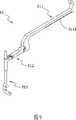
图9 为本实用新型外侧肌肉勾拉机构的外观立体图。Fig. 9 is a perspective view of the appearance of the outer muscle hooking mechanism of the present utility model.
图10 为本实用新型外侧肌肉勾拉机构的立体分解图。Fig. 10 is a three-dimensional exploded view of the outer muscle hooking mechanism of the present utility model.
图10A 为图10的连接单元的分解示意图。Figure 10A is an exploded schematic view of the connecting unit of Figure 10.
图11 为图10的连接单元的部份剖视图。Fig. 11 is a partial sectional view of the connection unit of Fig. 10.
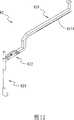
图12 为本实用新型内侧肌肉勾拉机构的外观立体图。Figure 12 is a perspective view of the appearance of the inner muscle hooking mechanism of the present utility model.
图13 为本实用新型内侧肌肉勾拉机构的立体分解图。Fig. 13 is a three-dimensional exploded view of the inner muscle hooking mechanism of the present utility model.
图13A 为图13的连接单元的分解示意图。Figure 13A is an exploded schematic diagram of the connection unit of Figure 13.
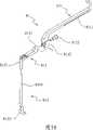
图14 为本实用新型神经勾拉机构的外观立体图。Figure 14 is a perspective view of the appearance of the nerve hooking mechanism of the present invention.
图15 为本实用新型神经勾拉机构的立体分解图。Fig. 15 is a three-dimensional exploded view of the nerve hooking mechanism of the present invention.
图15A 为图15的连接单元的分解示意图。Figure 15A is an exploded schematic view of the connecting unit of Figure 15.
图16 为图15的连接单元的部份剖视图。Fig. 16 is a partial sectional view of the connection unit of Fig. 15.
元件标号对照Component designation comparison
现有部分existing part
4……脊椎 41……肌肉4
42……工具 43……勾具42
5……套筒 51……脊椎5
52…肌肉 53……微型摄影机52
55……工具55... tools
本实用新型部分The utility model part
6……承载机构 61……环形导轨6
7……滑座机构 71……座体7...
711……弹簧座 712……楔槽711
713……C型孔 72……组接部713...C-
721……切槽 73……凹槽721
74……限制单元 741……止挡部74
742……压掣部 743……枢轴742...Depressing
744……凸块 745……第一弹簧744...Bump 745...First spring
746……扣爪 75……调整单元746...Claw claw 75...Adjusting unit
751……按压部 752……顶掣部751...
753……压板 754……第二弹簧753...Press
755……圆柱755...Cylinder
81……外侧肌肉勾拉机构 811……支架81...Lateral
8111……锯齿面 8112……接合部8111...
812……连接单元 8121……连接部812...
8122……万向接头 8123……套接部8122...Universal joint 8123...Socket
8124……弹簧 8125……枢杆8124...Spring 8125...Pivot
8126……顶持块 813……外侧肌肉勾8126...Holding block 813...Outside muscle hook
8131……杆体 8132……勾部8131...
82……内侧肌肉勾拉机构 821……支架82...Internal
8211……锯齿面 8212……接合部8211...Serrated surface 8212...Joint part
8213……枢轴 822……连接单元8213……Pivot 822……Connection unit
8221……连接部 8222……套接部8221...Connecting part 8222...Socketing part
8223……按压件 8224……顶块8223...Pressing piece 8224...Top block
8225……弹性元件 8226……枢杆8225...Elastic element 8226...Pivot
823……内侧肌肉勾 8231……杆体823...Internal muscle hook 8231...Rod body
8232……勾部 8233……齿条部8232...Hook part 8233...Rack part
83……神经勾拉机构 831……支架83...
8311……锯齿面 8312……接合部8311...Serrated surface 8312...Joint part
832……连接单元 832a……第一枢轴832...
832b…第二枢轴 832c…第三枢轴832b…
8321……连接部 8322……万向接头8321...Connecting part 8322...Universal joint
8323……套接部 8324……上座体8323...
8324a…前开孔 8324b…后开孔8324a...
8325……下座体 8326……按压件8325...
8326a…弹簧 8326b…突起8326a…
8327……弹性顶持块 8328……齿面扇形块8327...Elastic
833……神经勾 8331……杆体833...Nerve hook 8331...Rod body
8332……勾部8332...Hook department
具体实施方式Detailed ways
请参阅图4~16,如各图所示:本实用新型是一种微创腰椎手术的撑开装置,其至少是由一承载机构6、多数滑座机构7、至少二外侧肌肉勾拉机构81、一内侧肌肉勾拉机构82及一神经勾拉机构83所构成。Please refer to Figures 4 to 16, as shown in each figure: the utility model is a distraction device for minimally invasive lumbar spine surgery, which is at least composed of a bearing mechanism 6, a plurality of sliding
其中承载机构6为一外径在10至30cm范围内的环状导轨61,在20cm左右效果最佳,可通过一支撑臂固设于手术台上(图中未示)。Wherein the carrying mechanism 6 is an
滑座机构7具有一座体71,其上具有一呈一侧开口的框型(即呈ㄈ型开口状)组接部72(如图5~图8所示),该组接部72可活动结合于承载机构6的环形导轨61上,使得滑座机构7可于环形导轨61上任意移动位置进而固定,另于座体71的二侧分别设有一止挡部741以使其间形成有一凹槽73,该凹槽73二侧分别活动跨设有一限制单元74,同时于该座体71上设置有一楔槽712,该楔槽712内设有一调整单元75;其中各限制单元74向上延伸二相对应的扣爪746,且以一枢轴743与座体71的止挡部741枢接,使该对扣爪746分别位于止挡部741的前后两侧,利用扣爪746上的凸块744对应凹槽73的一侧内突,以对凹槽73形成限制作用。同时,另各限制单元74向下延伸一外倾的压掣部742,并以一贯穿座体71的第一弹簧745两端分别支撑两压掣部742,使得枢接于座体71上的至少二限制单元74保持上方扣爪746的凸块744对应凹槽73的一侧内突以形成限制作用,而下方的压掣部742保持外张(如图8所示);当相对按压压掣部742时,会使两限制单元74向上延伸的扣爪746对应凹槽73外张,以解除对凹槽73的限制作用。而调整单元75是由一按压部751、一由按压部751一端向上延伸的顶掣部752、一由按压部751横向延伸的压板753及一设置于座体71的弹簧座711内部与压板753间的第二弹簧754所构成。其中压板753设于座体71上的楔槽712内,并通过压板753末端有一圆柱755可嵌入楔槽712末端的C型孔713,以及楔槽712下方形成为下倾面空间,使得调整单元75的按压部751可向下按压,并使顶掣部752可向下移动;并由于第二弹簧754所提供的回复力,使得调整单元75的顶掣部752保持在上方顶掣位置,可参见图7所示。另外,座体71所形成的组接部72下方开设一切槽721,以供组接部72具有弹性,方便组合于环形导轨61上。The sliding
上述滑座机构7具有两主要功能,一是可于环形导轨61上位意移动位置进而固定;二是可快速组装各种不同功能的拉杆机构。The above-mentioned sliding
外侧肌肉勾拉机构81(如图9~11所示),主要是由一支架811、一连接单元812及一外侧肌肉勾813所构成。至少二外侧肌肉勾拉机构81的主要功能是将多裂肌(Multifidus muscle)向外侧拉开,其中支架811穿过滑座结构7的凹槽73,并被扣爪746上的凸块744限制而不致脱落,并在支架811底部具有一与滑座机构7的按压部751上的顶掣部752相互干涉的锯齿面8111,支架811的末端形成一接合部8112,该连接单元812的连接部8121与支架811的接合部8112是通过一万向接头8122组接,使得连接单元812可相对支架作角度调整;且连接单元812的一端设有一套接部8123,可参见图10A及图11所示,该套接部8123顶端于连接单元812内设有一顶持块8126,该顶持块8126通过一弹簧8124向套接部8123推顶,并以一枢杆8125自连接单元812外部贯穿顶持块8126以限制移动,套接部8123内供外侧肌肉勾813的杆体8131穿过,并以顶持块8126抵压持住定位,另外侧肌肉勾813是由一与连接单元812套接的杆体8131及一设于杆体8131一端的勾部8132所构成。The outer muscle hook pulling mechanism 81 (as shown in FIGS. 9 to 11 ) is mainly composed of a
内侧肌肉勾拉机构82(如图12及图13所示),主要是由一支架821、一连接单元822及一内侧肌肉勾823所构成。内侧肌肉勾拉机构82可将位于手术视野范围内侧的多裂肌向上拉开,以增加其内侧的视野,如此对于椎管狭窄的病人,可减轻椎管中央处(central canal)的压迫,其中支架821穿过滑座结构7的凹槽73,并被扣爪746上的凸块744限制而不致脱落,并在支架821底部具有一与滑座结构7的按压部751上的顶掣部752相互干涉的锯齿面8211,支架821的末端形成一接合部8212,该连接单元822的连接部8221与支架821的接合部8212通过一枢轴8213组接,使得连接单元822可相对支架821具有水平自由度;且连接单元822的连接部8221直向连通有一套接部8222,且该连接部8221上以一枢杆8226活动设有一按压件8223,该按压件8223的一端具有一设于套接部8222中的顶块8224,且该按压件8223与连接部8221之间设置有一弹性元件8225,可参见图13A所示,一枢杆8226自连接单元822外部贯穿按压件8223,使按压件8223在未被按压时保持顶块8224向套接部8222推抵,使顶块8224抵压内侧肌肉勾823杆体8231的齿条部8233以持住定位;而按压按压件8223会使顶块8224对内侧肌肉勾823顶持解除,此一设计使得内侧肌肉勾823具有相对上提的功能。套接部8222内供内侧肌肉勾823的杆体8231穿过,并以顶块8224抵压持住定位但可上提,另内侧肌肉勾823是由一连接单元822套接的杆体8231及一设于杆体8231一端的勾部8232所构成,并于杆体8231的一面上设有齿条部8233。The inner muscle hooking mechanism 82 (as shown in FIGS. 12 and 13 ) is mainly composed of a
神经勾拉机构83(如图14~图16所示),主要是由一支架831、一连接单元832及一神经勾833所构成。神经勾拉机构83可将神经根一次勾开并予以定位,以避免神经反复拨弄,其中支架831穿过滑座结构7的凹槽73,并被扣爪746上的凸块744限制而不致脱落,并在支架831底部具有一与滑座结构7的按压部751上的顶掣部752相互干涉的锯齿面8311,支架831的末端形成一接合部8312,该连接单元832的连接部8321与支架831的接合部8312通过一万向接头8322组接,使得连接单元832可相对支架831作角度调整;且连接单元832的一端设有一套接部8323,可参见图15A及图16所示,该套接部8323顶端延伸出一上座体8324,而连接部8321则延伸出一下座体8325,上座体8324具有一与套接部8323顶端相通且以第一枢轴832a贯穿前开孔8324a,使得下座体8325前端套合于前开孔8324a内并为枢接,同时使下座体8325前端的弹性顶持块8327自前开孔8324a伸入套接部8323的顶端,以持住神经勾833的杆体8331;另下座体8325则配合第二枢轴832b组接一齿面扇形块8328,并使该齿面扇形块8328伸入上座体8324的后开孔8324b;而上座体8324的后开孔8324b内则以第三枢轴832c枢接一按压件8326,该按压件8326设有一弹簧8326a,使得按压件8326前缘的一突起8326b可扣入齿面扇形块8328内,可参见图16所示,而按压件8326的作用是在提供所组装的神经勾833于垂直面上有弯曲的功能,另神经勾833是由一与连接单元832套接的杆体8331及一设于杆体8331一端的勾部8332所构成。The nerve hook pulling mechanism 83 (as shown in FIGS. 14 to 16 ) is mainly composed of a
上述所构成本实用新型的微创腰椎手术的撑开装置,于外侧肌肉勾拉机构81、内侧肌肉勾拉机构82及一神经勾拉机构83,每一拉杆机构的功能可归纳如下:The distraction device for minimally invasive lumbar surgery of the present invention constituted by the above-mentioned, in the outer
1.外侧肌肉勾拉机构81具有持住功能(以顶持块8126达成)、半万向功能(以万向接头8122及连接部8121达成)。1. The outer
2.内侧肌肉勾拉机构82具有上提功能(以按压件8223及顶块8224提供固定及止挡)、水平自由度(以接合部8212、枢轴8213及连接部8221枢接达成)。2. The inner
3.神经勾拉机构83具有持住功能(以弹性顶持块8327达成)、半万向功能(万向接头8322及连接部8321组接达成)、弯曲功能(由按压件8326及齿面扇形块8328达成)。3. The
但以上所述,仅为本实用新型的较佳实施例而已,当不能以此限定本实用新型实施的范围;故凡依本实用新型权利要求书及说明书内容所作的简单的等效变化与修饰,皆应仍属本实用新型专利涵盖的范围内。But the above are only preferred embodiments of the present utility model, and should not limit the scope of the utility model implementation; therefore all simple equivalent changes and modifications made according to the claims of the utility model and the contents of the description , all should still belong to the scope that the utility model patent covers.
Claims (18)
Translated fromChinesePriority Applications (1)
| Application Number | Priority Date | Filing Date | Title |
|---|---|---|---|
| CN 200720002115CN200994767Y (en) | 2007-01-15 | 2007-01-15 | A distraction device for minimally invasive lumbar surgery |
Applications Claiming Priority (1)
| Application Number | Priority Date | Filing Date | Title |
|---|---|---|---|
| CN 200720002115CN200994767Y (en) | 2007-01-15 | 2007-01-15 | A distraction device for minimally invasive lumbar surgery |
Publications (1)
| Publication Number | Publication Date |
|---|---|
| CN200994767Ytrue CN200994767Y (en) | 2007-12-26 |
Family
ID=38993180
Family Applications (1)
| Application Number | Title | Priority Date | Filing Date |
|---|---|---|---|
| CN 200720002115Expired - LifetimeCN200994767Y (en) | 2007-01-15 | 2007-01-15 | A distraction device for minimally invasive lumbar surgery |
Country Status (1)
| Country | Link |
|---|---|
| CN (1) | CN200994767Y (en) |
Cited By (6)
| Publication number | Priority date | Publication date | Assignee | Title |
|---|---|---|---|---|
| CN102166125A (en)* | 2011-04-23 | 2011-08-31 | 浙江大学 | Set of appliances for posterior lumbar interbody minimally invasive fusion |
| CN103126731A (en)* | 2013-01-30 | 2013-06-05 | 南京医科大学第一附属医院 | Exposure device for vertebral column back-way small-incision paraspinal muscle clearance admission passage |
| CN106264629A (en)* | 2016-11-04 | 2017-01-04 | 山东大学第二医院 | Scope skull base surgery drag hook and method |
| CN106943166A (en)* | 2017-04-27 | 2017-07-14 | 北京大学第三医院 | Surgical operation device for spreading |
| CN111603211A (en)* | 2020-06-09 | 2020-09-01 | 河南省中医院(河南中医药大学第二附属医院) | Spreading hooks in lumbar spine surgery |
| CN111956282A (en)* | 2020-08-26 | 2020-11-20 | 彭颖 | Shank wound distraction device that orthopedics was used |
- 2007
- 2007-01-15CNCN 200720002115patent/CN200994767Y/ennot_activeExpired - Lifetime
Cited By (10)
| Publication number | Priority date | Publication date | Assignee | Title |
|---|---|---|---|---|
| CN102166125A (en)* | 2011-04-23 | 2011-08-31 | 浙江大学 | Set of appliances for posterior lumbar interbody minimally invasive fusion |
| CN103126731A (en)* | 2013-01-30 | 2013-06-05 | 南京医科大学第一附属医院 | Exposure device for vertebral column back-way small-incision paraspinal muscle clearance admission passage |
| CN103126731B (en)* | 2013-01-30 | 2015-03-04 | 南京医科大学第一附属医院 | Exposure device for vertebral column back-way small-incision paraspinal muscle clearance admission passage |
| CN106264629A (en)* | 2016-11-04 | 2017-01-04 | 山东大学第二医院 | Scope skull base surgery drag hook and method |
| CN106943166A (en)* | 2017-04-27 | 2017-07-14 | 北京大学第三医院 | Surgical operation device for spreading |
| CN106943166B (en)* | 2017-04-27 | 2023-11-24 | 北京大学第三医院 | Surgical distraction device |
| CN111603211A (en)* | 2020-06-09 | 2020-09-01 | 河南省中医院(河南中医药大学第二附属医院) | Spreading hooks in lumbar spine surgery |
| CN111603211B (en)* | 2020-06-09 | 2021-04-06 | 河南省中医院(河南中医药大学第二附属医院) | Spreading hooks in lumbar spine surgery |
| CN111956282A (en)* | 2020-08-26 | 2020-11-20 | 彭颖 | Shank wound distraction device that orthopedics was used |
| CN111956282B (en)* | 2020-08-26 | 2022-08-05 | 聊城云购通信息技术有限公司 | Shank wound distraction device that orthopedics was used |
Similar Documents
| Publication | Publication Date | Title |
|---|---|---|
| US5059194A (en) | Cervical distractor | |
| US7811230B2 (en) | Expansion mechanism for minimally invasive lumbar operation | |
| CN200994767Y (en) | A distraction device for minimally invasive lumbar surgery | |
| EP2797529B1 (en) | Laminoplasty implant and instrumentation | |
| JP6998433B2 (en) | Minimal destructive retractor and related methods for spinal surgery | |
| JP5776117B2 (en) | Muscle retractor for spine surgery | |
| AU2004271986B2 (en) | Devices and methods for inserting spinal implants | |
| US9498261B2 (en) | Laminar hook insertion device | |
| US10070898B2 (en) | Instrument system for use with an interspinous implant | |
| US20030149341A1 (en) | Retractor and/or distractor for anterior cervical fusion | |
| US20060195102A1 (en) | Apparatus and method for treatment of spinal conditions | |
| JP2009509662A (en) | Modular intervertebral implants and instruments | |
| CN107106216A (en) | Spacer for laminoplasty | |
| KR20120075711A (en) | Minimally operation system for spinal surgical operation | |
| CA2189113A1 (en) | Vertebral distraction pump | |
| US11712271B2 (en) | Device and method to establish stabilization of the cervical spine without implantation of hardware or violation of the cortical bone | |
| CN214595977U (en) | Clavicle fracture closed reduction device | |
| CN203677228U (en) | Minimally invasive spinal internal fixation implantation operation device | |
| CN203280546U (en) | Dynamically-stable spinous process clamp | |
| CN105147411B (en) | The construction method and structure equipment of animal model with spinal cord damnification | |
| CN210019273U (en) | Oral cavity retractor system | |
| CN211355832U (en) | Plate holder for posterior cervical vertebra one-way open-door operation | |
| CN204994406U (en) | Experimental device for be used for preparing spinal cord veutro damage animal models | |
| CN203693716U (en) | Expanding device for vertebral plate | |
| KR101253663B1 (en) | Rod holder for minimal invasive surgery |
Legal Events
| Date | Code | Title | Description |
|---|---|---|---|
| C14 | Grant of patent or utility model | ||
| GR01 | Patent grant | ||
| COR | Change of bibliographic data | Free format text:CORRECT: CO-PATENTEE TO: XUE SHAOGANG ¬ | |
| CU01 | Correction of utility model | Correction item:Co-patentee Correct:Xue Shaogang Number:52 Page:The title page Volume:23 | |
| CU03 | Publication of corrected utility model | Correction item:Co-patentee Correct:Xue Shaogang Number:52 Volume:23 | |
| ERR | Gazette correction | Free format text:CORRECT: CO-PATENTEE; FROM: NONE ¬ TO: XUE SHAOGANG ¬ | |
| CX01 | Expiry of patent term | Granted publication date:20071226 | |
| EXPY | Termination of patent right or utility model |