CN200947406Y - Keyboard assembly fixture - Google Patents
Keyboard assembly fixtureDownload PDFInfo
- Publication number
- CN200947406Y CN200947406YCN 200620133005CN200620133005UCN200947406YCN 200947406 YCN200947406 YCN 200947406YCN 200620133005CN200620133005CN 200620133005CN 200620133005 UCN200620133005 UCN 200620133005UCN 200947406 YCN200947406 YCN 200947406Y
- Authority
- CN
- China
- Prior art keywords
- adhesive film
- keyboard
- bottom plate
- assembled fixture
- moving part
- Prior art date
- Legal status (The legal status is an assumption and is not a legal conclusion. Google has not performed a legal analysis and makes no representation as to the accuracy of the status listed.)
- Expired - Fee Related
Links
Images


Landscapes
- Push-Button Switches (AREA)
- Input From Keyboards Or The Like (AREA)
Abstract
Description
Translated fromChinese技术领域technical field
本实用新型涉及一种键盘组装治具及其组装方法,特别是涉及一种用以将键盘底板与背胶膜相互黏贴的治具及其组装方法,其治具的结构简单,操作方式容易,对位精准且组装快速,并可保持黏胶层洁净度,可提高产能及产品合格率。The utility model relates to a keyboard assembly jig and an assembly method thereof, in particular to a jig for adhering a keyboard bottom plate and an adhesive film to each other and an assembly method thereof. The jig has a simple structure and is easy to operate , accurate alignment and fast assembly, and can maintain the cleanliness of the adhesive layer, which can improve production capacity and product qualification rate.
背景技术Background technique
一般常见的现有一种键盘的结构,其具有一铝或钢等金属材质的支撑用底板,该底板底面必须贴附一背胶膜,以构成一键盘半成品提供后续与电路板组装等制作工艺使用,而且目前一般业者均是采用人手配合目测的方式将背胶膜贴合于底板上,贴合时必须留意二者定位问题,因人手黏贴产生歪斜也会使得黏胶层外漏于底板外,不仅不美观,且容易沾黏灰尘等杂物,再者,因背胶膜的厚度极薄,对于长宽尺寸可达30公分×11公分的大型底板而言,所相对应的背胶膜尺寸也相对增加,不仅黏附困难度提高,不易对准、容易歪斜,或造成绉折、气泡,且当剥离该背胶膜的离形纸后,人手不易抓持,常不慎碰触黏胶层影响黏度及其洁净度。Generally, there is a common keyboard structure, which has a support base plate made of metal such as aluminum or steel, and a back adhesive film must be attached to the bottom surface of the base plate to form a semi-finished keyboard for subsequent use in manufacturing processes such as circuit board assembly. , and at present, the general industry is to stick the adhesive film on the bottom plate by manual and visual inspection. When pasting, you must pay attention to the positioning of the two. The skew caused by manual sticking will also cause the adhesive layer to leak outside the bottom plate. , not only unsightly, but also easy to stick to dust and other sundries. Furthermore, because the thickness of the adhesive film is extremely thin, for a large base plate with a length and width of 30 cm × 11 cm, the corresponding adhesive film The size is relatively increased, not only the difficulty of adhesion is increased, it is difficult to align, it is easy to be skewed, or it may cause creases and air bubbles, and when the release paper of the adhesive film is peeled off, it is difficult for human hands to grasp and often accidentally touch the adhesive. The layer affects the viscosity and its cleanliness.
实用新型内容Utility model content
有鉴于现有技术的缺陷,本实用新型的主要目的在于提出一种键盘组装治具及其组装方法,该键盘组装治具的结构简单,操作方式容易,对位精准且组装快速,并可保持黏胶层洁净度,可提高产能及产品合格率。In view of the defects of the prior art, the main purpose of this utility model is to propose a keyboard assembly jig and its assembly method. The keyboard assembly jig has a simple structure, easy operation, accurate alignment and fast assembly, and can maintain The cleanliness of the adhesive layer can improve production capacity and product qualification rate.
为达到上述目的,本实用新型提出一种键盘组装治具,用以将一底板及一背胶膜相互组合,该背胶膜具有黏性,且该底板及该背胶膜分别设有相对应的多个定位孔,该组装治具包括:In order to achieve the above object, the utility model proposes a keyboard assembly jig for assembling a bottom plate and an adhesive film. The adhesive film is sticky, and the bottom plate and the adhesive film are provided with corresponding Multiple positioning holes, the assembly jig includes:
一治具平台;A fixture platform;
多个定位柱,相对应于该底板及背胶膜的定位孔位置设置于该治具平台上;A plurality of positioning columns are arranged on the jig platform corresponding to the positions of the positioning holes of the bottom plate and the adhesive film;
一升降机构,用以控制该多个定位柱可做升降移动。A lifting mechanism is used to control the plurality of positioning columns to move up and down.
较佳地,该升降机构为一连动件,且该多个定位柱设置在该连动件上,当该连动件下降时,可使该多个的定位柱同步下沉。Preferably, the lifting mechanism is a linkage, and the plurality of positioning columns are arranged on the linkage, and when the linkage is lowered, the plurality of positioning columns can be lowered synchronously.
较佳地,该连动件配置于一弹性元件上,以提供该连动件可于一按压位置以及一释放位置之间弹性往复运动,当该连动件下降至按压位置时,该多个定位柱可同步下沉;当该弹性元件使该连动件弹至释放位置时,该多个定位柱凸伸于该治具平台上。Preferably, the linkage is arranged on an elastic element, so that the linkage can elastically reciprocate between a pressing position and a release position. When the linkage descends to the pressing position, the plurality of The positioning posts can be sunk synchronously; when the elastic element makes the linkage member spring to the release position, the multiple positioning posts protrude from the jig platform.
较佳地,该弹性元件可为弹簧、弹片其中之一或其组合。Preferably, the elastic element can be one of a spring, a shrapnel or a combination thereof.
较佳地,该升降机构为一控制电路,且该控制电路与该多个定位柱电连接,通过触动该控制电路继而可控制该多个定位柱升降。Preferably, the lifting mechanism is a control circuit, and the control circuit is electrically connected to the plurality of positioning columns, and the control circuit can then control the lifting of the plurality of positioning columns.
较佳地,该控制电路更包括一驱动装置,用以控制该多个定位柱升降。Preferably, the control circuit further includes a driving device for controlling the lifting and lowering of the plurality of positioning posts.
较佳地,该驱动装置可为气压装置、液压装置或油压装置其中之一或其组合。Preferably, the driving device can be one of pneumatic device, hydraulic device or hydraulic device or a combination thereof.
较佳地,该底板及该背胶膜可配置于一键盘内。Preferably, the base plate and the adhesive film can be disposed in a keyboard.
较佳地,该键盘结构可为计算机、移动电话,或个人数字助理(PDA)的键盘结构。Preferably, the keyboard structure can be that of a computer, a mobile phone, or a personal digital assistant (PDA).
为达到上述目的,本实用新型更提出一种组装方法,包括下列步骤:In order to achieve the above object, the utility model further proposes an assembly method, which includes the following steps:
a.控制该升降机构,使定位柱上升并凸伸于该治具平台上;a. Control the lifting mechanism so that the positioning column rises and protrudes on the jig platform;
b.依序将构件套入相对应的定位柱,且该底板及背胶膜可落于治具平台上;b. Insert the components into the corresponding positioning columns in sequence, and the bottom plate and adhesive film can fall on the fixture platform;
c.施压于最顶部的构件,使该底板及背胶膜相互黏合;c. Apply pressure to the topmost member to make the bottom plate and the back adhesive film adhere to each other;
d.控制该升降机构,使定位柱下沉于该治具平台下;d. Control the lifting mechanism so that the positioning column sinks under the fixture platform;
e.取出黏合后的该底板及该背胶膜;e. Take out the bonded bottom plate and the adhesive film;
较佳地,在该步骤a中,更包括一剥离离形纸的步骤,将具有黏胶层的构件套入相对应的定位柱后,再将离形纸剥离。Preferably, in the step a, a step of peeling off the release paper is further included, and after inserting the member with the adhesive layer into the corresponding positioning post, the release paper is peeled off.
较佳地,该升降机构为一连动件,且该多个定位键设置在该连动件上,使进行步骤c时,当该连动件下降时,可使该多个定位柱同步下沉。Preferably, the lifting mechanism is a linkage, and the plurality of positioning keys are arranged on the linkage, so that when the linkage is lowered during step c, the plurality of positioning columns can be lowered synchronously Shen.
较佳地,该连动件配置于一弹性元件上,以提供该连动件可于一按压位置以及一释放位置之间弹性往复运动,当该连动件下降至按压位置时,该多个定位柱可同步下沉;当该弹性元件使该连动件弹至释放位置时,该多个定位柱凸伸于该治具平台上。Preferably, the linkage is arranged on an elastic element, so that the linkage can elastically reciprocate between a pressing position and a release position. When the linkage descends to the pressing position, the plurality of The positioning posts can be sunk synchronously; when the elastic element makes the linkage member spring to the release position, the multiple positioning posts protrude from the jig platform.
较佳地,该弹性元件可为弹簧、弹片其中之一或其组合。Preferably, the elastic element can be one of a spring, a shrapnel or a combination thereof.
较佳地,该升降机构为一控制电路,且该控制电路与该多个定位柱电连接,使进行步骤c时,通过触动该控制电路继而可控制该多个定位柱升降。Preferably, the lifting mechanism is a control circuit, and the control circuit is electrically connected to the plurality of positioning columns, so that when step c is performed, the control circuit can be activated to control the lifting of the plurality of positioning columns.
较佳地,该控制电路更包括一驱动装置,用以控制该多个定位柱升降。Preferably, the control circuit further includes a driving device for controlling the lifting and lowering of the plurality of positioning posts.
较佳地,该驱动装置可为气压装置、液压装置或油压装置其中之一或其组合。Preferably, the driving device can be one of pneumatic device, hydraulic device or hydraulic device or a combination thereof.
较佳地,,该背胶膜具有黏胶层用以与该底板黏贴,在该步骤a中,依序将背胶膜及底板放入该组装治具,且该背胶膜的黏胶层是朝向底板。Preferably, the adhesive film has an adhesive layer for sticking to the base plate, in step a, the adhesive film and the base plate are put into the assembly jig in sequence, and the adhesive of the adhesive film Layers are towards the base plate.
较佳地,其先将其背胶膜的黏胶层上的离形纸剥离,而后再套入底板。Preferably, it first peels off the release paper on the adhesive layer of its back adhesive film, and then inserts it into the bottom plate.
较佳地,该步骤b可通过人工或机械其中之一或其组合的方式提供压力。Preferably, the step b can provide pressure manually or mechanically or a combination thereof.
本实用新型的优点在于,其治具的结构简单,操作方式容易,对位精准且组装快速,并可保持黏胶层洁净度,提高产能及产品合格率。The utility model has the advantages that the jig has a simple structure, easy operation, accurate alignment and fast assembly, and can maintain the cleanliness of the adhesive layer, thereby improving production capacity and product qualification rate.
为使贵审查委员对于本实用新型的结构目的和功效有更进一步的了解与认同,兹配合图示详细说明如后。In order to make your examining committee members have a further understanding and recognition of the structure, purpose and efficacy of the utility model, hereby cooperate with the illustrations to describe in detail as follows.
附图说明Description of drawings
图1为本实用新型较佳实施例的外观示意图;Fig. 1 is the appearance schematic diagram of the preferred embodiment of the utility model;
图2及图3为本实用新型较佳实施例的动作示意图;Fig. 2 and Fig. 3 are the action schematic diagrams of the preferred embodiment of the present utility model;
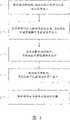
图4为本实用新型的步骤流程图。Fig. 4 is a flow chart of steps of the present utility model.
主要元件符号说明:Description of main component symbols:
20-组装治具20-Assembly jig
21-治具平台21-Jig platform
211-连动件211-Linkage
212-弹簧212-spring
213-限位块213-limit block
22-定位柱22-Positioning column
23-升降机构23- Lifting mechanism
41-底板41-bottom plate
43-背胶膜43-adhesive film
411、431-定位孔411, 431-positioning holes
H-高度H-height
P1-释放位置P1 - release position
P2-按压位置P2-press position
具体实施方式Detailed ways
以下将参照附图来描述本实用新型为达成目的所使用的技术手段与功效,而以下图式所列举的实施例仅为辅助说明,以利贵审查委员了解,但本实用新型的技术手段并不限于所列举图式。The technical means and effects used by the utility model to achieve the purpose will be described below with reference to the accompanying drawings, and the embodiments listed in the following drawings are only auxiliary explanations to facilitate the understanding of the examiners, but the technical means of the utility model are not Not limited to the listed drawings.
请参阅图1所示,本实用新型提供的组装治具20,具有一治具平台21,在该治具平台21上设有多个定位柱22,该多个定位柱22通过一升降机构23控制可同步作垂直于该治具平台21的升降移动,该治具平台21的大小是依组装构件的尺寸而定,以略大于组装构件的尺寸为宜,该定位柱22所设置的位置以及数量,也因组装构件尺寸不同而异,以图1所示构件,其依序包括一背胶膜43、一底板41,该类构件结构常见于计算机、移动电话,或个人数字助理(PDA)的键盘结构,该背胶膜43具有黏胶层(图中未示出)用以与底板41黏贴,该背胶膜43及该底板41的相对应位置均设有定位孔431、411,该定位柱22则相对应该定位孔431、411的位置设置于该治具平台21上。Please refer to Fig. 1, the
有关该升降机构23控制该多个定位柱22同步垂直升降移动的方式,请参阅图2及图3所示,在该治具平台21内部设有一连动件211,该多个定位柱22的底部穿透该治具平台21设置于该连动件211上,该连动件211配置于多个弹簧212上,通过该多个弹簧212的弹性,可提供该连动件211于一释放位置P1以及一按压位置P2之间弹性往复运动,也可采用弹片或其它具有弹性的弹性元件取代该弹簧212,至于该释放位置P1及按压位置P2的设定,依构件的厚度、定位柱22的长度等等因素而设定,其设定的原则在于,当该连动件211下降至按压位置P2时,可使定位柱22同步下沉,且其下沉的深度是以易于取出该底板41及该背胶膜43为原则,同时,可于该连动件211底部设置限位块213,用以界定该按压位置P2,亦即该定位柱22下沉的深度,至于该释放位置P1则可使得当该弹簧212使该连动件211弹至释放位置P1时,该定位柱22凸伸于该治具平台21上,且其凸伸的高度H至少可满足将所有构件(如图1所示的背胶膜43、底板41)套入即可。Regarding the manner in which the elevating
如图2所示,当该连动件211未受力时,该连动件211是自然位于该释放位置P1,定位柱22凸伸于该治具平台21上,此时,可依序将该背胶膜43、底板41套入定位柱22,当然,该背胶膜43具有黏胶层的面是朝向上方,将该背胶膜43套设于该定位柱22后,该背胶膜43可自然落于该治具平台21上,再将底板41套上后,底板41可自然落于该背胶膜43上,而后再适度施压于该底板41上,使该底板41与该背胶膜43二者确实黏合,而后如图3所示,当该连动件211下降至按压位置P2时,该多个定位柱22可同步下沉于该治具平台21下,此时可将已黏合的底板41与背胶膜43取出该治具平台21,而后再释放该连动件211,使该连动件211自动上升至释放位置P1,使该多个定位柱22再度凸伸于该治具平台21上,即可进行下一键盘的组装。As shown in Figure 2, when the
有关前述该升降机构23控制定位柱22升降的方式属于纯机械式,除此之外,该升降机构也可为一控制电路(图中未示出)且电连接该定位柱22,而该控制电路可连动于气压装置、液压装置或油压装置等驱动装置,用以驱动该多个定位柱22升降,此属于现有技术,在此不予赘述。The manner in which the
根据以上结构,可归纳本实用新型提供的组装治具20的组装方法如图4所示,包括下列步骤:According to the above structure, it can be concluded that the assembly method of the
释放该升降机构,使定位柱上升并凸伸于该治具平台上Release the lifting mechanism, so that the positioning column rises and protrudes on the fixture platform
依序将构件套入相对应的定位柱,且该底板及该背胶膜可落于治具平台上;Sequentially insert the components into the corresponding positioning columns, and the bottom plate and the adhesive film can fall on the jig platform;
施压于最顶部的构件,使该底板及背胶膜相互黏合;Apply pressure to the topmost member to make the bottom plate and the back adhesive film adhere to each other;
控制该升降机构,使定位柱下沉于该治具平台下;Control the lifting mechanism so that the positioning column sinks under the jig platform;
取出黏合后的该底板及该背胶模;taking out the bonded base plate and the adhesive mold;
在该步骤(a)中,更包括一剥离离形纸的步骤,将具有黏胶层的构件套入相对应的定位柱后,再将离形纸剥离,以图1为例,先将该背胶膜43套入定位柱22后,再将其上的离形纸(图中未示出)剥离,而后再套入底板41。In this step (a), a step of peeling off the release paper is further included. After inserting the member with the adhesive layer into the corresponding positioning column, the release paper is peeled off. Taking Figure 1 as an example, first place the After the
综上所述,本实用新型提供的治具的结构简单,操作方式容易,对位精准且组装快速,并可保持黏胶层洁净度,提高产能及产品合格率。To sum up, the jig provided by the utility model has simple structure, easy operation, accurate alignment and fast assembly, and can maintain the cleanliness of the adhesive layer, thereby improving production capacity and product qualification rate.
Claims (8)
Priority Applications (1)
| Application Number | Priority Date | Filing Date | Title |
|---|---|---|---|
| CN 200620133005CN200947406Y (en) | 2006-08-16 | 2006-08-16 | Keyboard assembly fixture |
Applications Claiming Priority (1)
| Application Number | Priority Date | Filing Date | Title |
|---|---|---|---|
| CN 200620133005CN200947406Y (en) | 2006-08-16 | 2006-08-16 | Keyboard assembly fixture |
Publications (1)
| Publication Number | Publication Date |
|---|---|
| CN200947406Ytrue CN200947406Y (en) | 2007-09-12 |
Family
ID=38734471
Family Applications (1)
| Application Number | Title | Priority Date | Filing Date |
|---|---|---|---|
| CN 200620133005Expired - Fee RelatedCN200947406Y (en) | 2006-08-16 | 2006-08-16 | Keyboard assembly fixture |
Country Status (1)
| Country | Link |
|---|---|
| CN (1) | CN200947406Y (en) |
Cited By (14)
| Publication number | Priority date | Publication date | Assignee | Title |
|---|---|---|---|---|
| CN104108487A (en)* | 2013-04-22 | 2014-10-22 | 上海景奕电子科技有限公司 | Foam assembling jig |
| CN104272221A (en)* | 2012-05-15 | 2015-01-07 | 微软公司 | Input device manufacture |
| CN105914076A (en)* | 2016-03-21 | 2016-08-31 | 珠海格力电器股份有限公司 | Keyboard assembling jig and keyboard assembling method |
| CN106024461A (en)* | 2016-07-28 | 2016-10-12 | 淮安达方电子有限公司 | Keyboard assembling fixture |
| US9661770B2 (en) | 2012-10-17 | 2017-05-23 | Microsoft Technology Licensing, Llc | Graphic formation via material ablation |
| US9678542B2 (en) | 2012-03-02 | 2017-06-13 | Microsoft Technology Licensing, Llc | Multiple position input device cover |
| US9706089B2 (en) | 2012-03-02 | 2017-07-11 | Microsoft Technology Licensing, Llc | Shifted lens camera for mobile computing devices |
| US9710093B2 (en) | 2012-03-02 | 2017-07-18 | Microsoft Technology Licensing, Llc | Pressure sensitive key normalization |
| US9793073B2 (en) | 2012-03-02 | 2017-10-17 | Microsoft Technology Licensing, Llc | Backlighting a fabric enclosure of a flexible cover |
| US9870066B2 (en) | 2012-03-02 | 2018-01-16 | Microsoft Technology Licensing, Llc | Method of manufacturing an input device |
| US9959241B2 (en) | 2012-05-14 | 2018-05-01 | Microsoft Technology Licensing, Llc | System and method for accessory device architecture that passes via intermediate processor a descriptor when processing in a low power state |
| US10031556B2 (en) | 2012-06-08 | 2018-07-24 | Microsoft Technology Licensing, Llc | User experience adaptation |
| CN110797222A (en)* | 2019-09-26 | 2020-02-14 | 贵派电器股份有限公司 | Method for manufacturing switch key button with decoration |
| WO2020134639A1 (en)* | 2018-12-27 | 2020-07-02 | 苏州维旺科技有限公司 | Fixing device for polishing apparatus and polishing system |
- 2006
- 2006-08-16CNCN 200620133005patent/CN200947406Y/ennot_activeExpired - Fee Related
Cited By (22)
| Publication number | Priority date | Publication date | Assignee | Title |
|---|---|---|---|---|
| US9946307B2 (en) | 2012-03-02 | 2018-04-17 | Microsoft Technology Licensing, Llc | Classifying the intent of user input |
| US9852855B2 (en) | 2012-03-02 | 2017-12-26 | Microsoft Technology Licensing, Llc | Pressure sensitive key normalization |
| US10963087B2 (en) | 2012-03-02 | 2021-03-30 | Microsoft Technology Licensing, Llc | Pressure sensitive keys |
| US10013030B2 (en) | 2012-03-02 | 2018-07-03 | Microsoft Technology Licensing, Llc | Multiple position input device cover |
| US9904327B2 (en) | 2012-03-02 | 2018-02-27 | Microsoft Technology Licensing, Llc | Flexible hinge and removable attachment |
| US9766663B2 (en) | 2012-03-02 | 2017-09-19 | Microsoft Technology Licensing, Llc | Hinge for component attachment |
| US9678542B2 (en) | 2012-03-02 | 2017-06-13 | Microsoft Technology Licensing, Llc | Multiple position input device cover |
| US9706089B2 (en) | 2012-03-02 | 2017-07-11 | Microsoft Technology Licensing, Llc | Shifted lens camera for mobile computing devices |
| US9710093B2 (en) | 2012-03-02 | 2017-07-18 | Microsoft Technology Licensing, Llc | Pressure sensitive key normalization |
| US9870066B2 (en) | 2012-03-02 | 2018-01-16 | Microsoft Technology Licensing, Llc | Method of manufacturing an input device |
| US9793073B2 (en) | 2012-03-02 | 2017-10-17 | Microsoft Technology Licensing, Llc | Backlighting a fabric enclosure of a flexible cover |
| US9959241B2 (en) | 2012-05-14 | 2018-05-01 | Microsoft Technology Licensing, Llc | System and method for accessory device architecture that passes via intermediate processor a descriptor when processing in a low power state |
| CN104272221A (en)* | 2012-05-15 | 2015-01-07 | 微软公司 | Input device manufacture |
| CN104272221B (en)* | 2012-05-15 | 2018-03-02 | 微软技术许可有限责任公司 | Input equipment manufactures |
| US10031556B2 (en) | 2012-06-08 | 2018-07-24 | Microsoft Technology Licensing, Llc | User experience adaptation |
| US9661770B2 (en) | 2012-10-17 | 2017-05-23 | Microsoft Technology Licensing, Llc | Graphic formation via material ablation |
| CN104108487A (en)* | 2013-04-22 | 2014-10-22 | 上海景奕电子科技有限公司 | Foam assembling jig |
| CN104108487B (en)* | 2013-04-22 | 2016-07-06 | 上海景奕电子科技有限公司 | A kind of foam assembled fixture |
| CN105914076A (en)* | 2016-03-21 | 2016-08-31 | 珠海格力电器股份有限公司 | Keyboard assembling jig and keyboard assembling method |
| CN106024461A (en)* | 2016-07-28 | 2016-10-12 | 淮安达方电子有限公司 | Keyboard assembling fixture |
| WO2020134639A1 (en)* | 2018-12-27 | 2020-07-02 | 苏州维旺科技有限公司 | Fixing device for polishing apparatus and polishing system |
| CN110797222A (en)* | 2019-09-26 | 2020-02-14 | 贵派电器股份有限公司 | Method for manufacturing switch key button with decoration |
Similar Documents
| Publication | Publication Date | Title |
|---|---|---|
| CN200947406Y (en) | Keyboard assembly fixture | |
| CN203983240U (en) | For the manufacture of the device of display device | |
| CN104097383A (en) | JIG ASSEMBLY and LAMINATING APPARATUS | |
| CN2701627Y (en) | Film tearing machine | |
| CN1525509A (en) | Keyboard switch mechanism | |
| CN1725404A (en) | Key sheet and method for manufacturing key sheet | |
| CN1245855C (en) | Multilayer wiring board, touch face-plate and their manufacturing method | |
| CN114572673B (en) | Intelligent heat insulation plate combined machining device with offset compensation mechanism | |
| CN1831645A (en) | Device for making fine patterns | |
| CN209546033U (en) | A kind of FPC shells gluing mechanism automatically | |
| CN1226762C (en) | Movable contact body with operation protrusion, installation method and application of the operation protrusion | |
| CN1927584A (en) | Fully automatic visual printing machine PCB board fixture system and composition method | |
| CN204450272U (en) | Lower cavity positioning and clamping mechanism of vacuum laminating machine | |
| CN108638343B (en) | Drilling device for thick plate glass | |
| TWI396655B (en) | Substrate-separating fixture and method for separating substrates | |
| TW201607767A (en) | Carrier stripping device | |
| TWI325291B (en) | Assembly fixture and the method thereof | |
| CN101656222B (en) | Nested support pillar equipment | |
| CN2721379Y (en) | Disk vacuum bonding device | |
| TWI381411B (en) | Gathering method and apparatus for a keypad fabrication process | |
| CN216565750U (en) | A FPC automatic glue board machine | |
| CN218976963U (en) | High multi-layer laminated circuit board pressing table device | |
| WO2021238060A1 (en) | Flexible substrate and mechanical stripping method therefor | |
| JP2007206580A (en) | Film carrying-out device and method | |
| CN221378615U (en) | Touch-sensitive screen laminating tool |
Legal Events
| Date | Code | Title | Description |
|---|---|---|---|
| C14 | Grant of patent or utility model | ||
| GR01 | Patent grant | ||
| C17 | Cessation of patent right | ||
| CF01 | Termination of patent right due to non-payment of annual fee | Granted publication date:20070912 Termination date:20090916 |