CN1987935B - Paper identification device, paper processing device, and paper identification method - Google Patents
Paper identification device, paper processing device, and paper identification methodDownload PDFInfo
- Publication number
- CN1987935B CN1987935BCN2006101685618ACN200610168561ACN1987935BCN 1987935 BCN1987935 BCN 1987935BCN 2006101685618 ACN2006101685618 ACN 2006101685618ACN 200610168561 ACN200610168561 ACN 200610168561ACN 1987935 BCN1987935 BCN 1987935B
- Authority
- CN
- China
- Prior art keywords
- paper
- unit
- detecting unit
- type
- correction coefficient
- Prior art date
- Legal status (The legal status is an assumption and is not a legal conclusion. Google has not performed a legal analysis and makes no representation as to the accuracy of the status listed.)
- Active
Links
Images


Classifications
- G—PHYSICS
- G07—CHECKING-DEVICES
- G07D—HANDLING OF COINS OR VALUABLE PAPERS, e.g. TESTING, SORTING BY DENOMINATIONS, COUNTING, DISPENSING, CHANGING OR DEPOSITING
- G07D7/00—Testing specially adapted to determine the identity or genuineness of valuable papers or for segregating those which are unacceptable, e.g. banknotes that are alien to a currency
- G07D7/06—Testing specially adapted to determine the identity or genuineness of valuable papers or for segregating those which are unacceptable, e.g. banknotes that are alien to a currency using wave or particle radiation
- G07D7/12—Visible light, infrared or ultraviolet radiation
- G—PHYSICS
- G01—MEASURING; TESTING
- G01B—MEASURING LENGTH, THICKNESS OR SIMILAR LINEAR DIMENSIONS; MEASURING ANGLES; MEASURING AREAS; MEASURING IRREGULARITIES OF SURFACES OR CONTOURS
- G01B11/00—Measuring arrangements characterised by the use of optical techniques
- G01B11/30—Measuring arrangements characterised by the use of optical techniques for measuring roughness or irregularity of surfaces
- G—PHYSICS
- G06—COMPUTING OR CALCULATING; COUNTING
- G06V—IMAGE OR VIDEO RECOGNITION OR UNDERSTANDING
- G06V10/00—Arrangements for image or video recognition or understanding
- G06V10/10—Image acquisition
- G—PHYSICS
- G06—COMPUTING OR CALCULATING; COUNTING
- G06V—IMAGE OR VIDEO RECOGNITION OR UNDERSTANDING
- G06V10/00—Arrangements for image or video recognition or understanding
- G06V10/40—Extraction of image or video features
- G—PHYSICS
- G07—CHECKING-DEVICES
- G07D—HANDLING OF COINS OR VALUABLE PAPERS, e.g. TESTING, SORTING BY DENOMINATIONS, COUNTING, DISPENSING, CHANGING OR DEPOSITING
- G07D7/00—Testing specially adapted to determine the identity or genuineness of valuable papers or for segregating those which are unacceptable, e.g. banknotes that are alien to a currency
- G07D7/06—Testing specially adapted to determine the identity or genuineness of valuable papers or for segregating those which are unacceptable, e.g. banknotes that are alien to a currency using wave or particle radiation
- G07D7/12—Visible light, infrared or ultraviolet radiation
- G07D7/128—Viewing devices
Landscapes
- Health & Medical Sciences (AREA)
- General Health & Medical Sciences (AREA)
- Toxicology (AREA)
- Physics & Mathematics (AREA)
- General Physics & Mathematics (AREA)
- Engineering & Computer Science (AREA)
- Multimedia (AREA)
- Theoretical Computer Science (AREA)
- Inspection Of Paper Currency And Valuable Securities (AREA)
- Investigating Or Analysing Materials By Optical Means (AREA)
Abstract
Translated fromChineseDescription
Translated fromChinese技术领域technical field
本发明涉及通过对纸张进行检查,对污损等级或真/伪进行鉴别的纸张鉴别(discrimination)设备,以及具有纸张鉴别设备的纸张处理设备和纸张鉴别方法。The present invention relates to paper discrimination (discrimination) apparatus for discriminating stain level or true/false by inspecting paper, paper processing apparatus having paper discrimination apparatus and paper discrimination method.
背景技术Background technique
通常,纸张鉴别设备按照如下方式确定关于纸张污损等级的标准。即,通过将用于调节的介质或者为调节准备的纸张本身馈送到设备中,对取决于设备之间的个体差异的鉴别等级之间的差异进行校正,(例如,参照日本专利申请KOKAI公报No.2003-99837)。Generally, a paper discriminating apparatus determines a standard regarding a paper soiling level as follows. That is, by feeding the medium used for adjustment or the paper itself prepared for adjustment into the device, the difference between authentication levels depending on the individual difference between devices is corrected, (for example, refer to Japanese Patent Application KOKAI Gazette No. .2003-99837).
例如,当有作为鉴别对象的五种纸张时,可以将以下三种方法当作对鉴别等级进行校正的方法。For example, when there are five kinds of sheets as objects of authentication, the following three methods can be considered as methods of correcting the authentication level.
在第一种方法中,以每种1000张为单位,沿着四个方向(正面向前、正面向后、背面向前和背面向后),馈送这五种纸张,收集总共20种污损量的频率分布数据(直方图),并且根据频率分布数据确定关于污损的鉴别等级的标准。In the first method, the five kinds of sheets were fed in units of 1000 sheets each in four directions (front-to-front, front-to-back, back-to-front, and back-to-back), and a total of 20 stains were collected. Quantitative frequency distribution data (histogram), and based on the frequency distribution data to determine the criteria for the identification level of contamination.
在第二种方法中,制造五种用于调节的介质,在光学上,这些介质的特性近似于未经使用的作为鉴别对象的纸张,并且,将这些介质馈送到设备中,以便收集频率分布数据。然后,通过假设介质被损坏并被污染的情况,根据用于调节的介质的分布数据,确定关于污损的鉴别等级的标准。In the second method, five kinds of media for conditioning, optically similar in characteristics to unused paper as an object of identification, were manufactured and fed into the device to collect the frequency distribution data. Then, by assuming a situation where the medium is damaged and contaminated, the criteria for the discrimination level of contamination are determined based on the distribution data of the medium used for conditioning.
另外,在第三种方法中,为每一种纸张制造处于介质被污染并被损坏的再生状态中的、用于调节的十种介质,并且,将用于调节的总共五十种介质馈送到设备中,以便收集其频率分布数据。然后,根据具有不同污损等级的多种介质的分布数据,确定关于污损的鉴别等级的标准。In addition, in the third method, ten media for conditioning are produced for each paper in a recycled state where the media are soiled and damaged, and a total of fifty media for conditioning are fed to device in order to collect data on its frequency distribution. Then, based on the distribution data of a plurality of media having different levels of fouling, criteria for discriminating levels of fouling are determined.
但是,按照第一种方法,纸张本身有光学变化。此外,由于介质随使用而损坏,并且污染条件损坏(stain condition damage)偏离了初始的污染条件损坏,因此,不可能持续保持正确的标准。However, according to the first method, the paper itself undergoes optical changes. Furthermore, since the media deteriorates with use and the stain condition damage deviates from the initial stain condition damage, it is impossible to maintain the correct standard consistently.
按照第二种方法,可以通过定期进行更换,保持用于调节的介质的质量。但是,难以制造出光学特性与作为鉴别对象的纸张的光学特性完全一致的用于调节的介质,并且,不可能对具有不同特性的多个设备进行高精度校正。According to the second method, the quality of the media used for conditioning can be maintained by regular replacement. However, it is difficult to manufacture a medium for adjustment whose optical characteristics completely coincide with those of the paper to be discriminated against, and it is impossible to perform high-precision correction for a plurality of devices having different characteristics.
此外,按照第三种方法,可以按照与第二种方法相同的方式,保持用于调节的介质的质量。但是,难以制造出比第二种方法更多的用于调节的介质,并且,不可能对设备进行高精度校正。Furthermore, according to the third method, the quality of the medium used for conditioning can be maintained in the same manner as the second method. However, it is difficult to manufacture more media for adjustment than in the second method, and it is impossible to calibrate the device with high precision.
发明内容Contents of the invention
本发明的目的是提供一种能够容易地而且精确地对设备之间的鉴别性能方面的差别进行校正的纸张鉴别设备以及纸张处理设备和纸张鉴别方法。An object of the present invention is to provide a paper discriminating device capable of easily and accurately correcting a difference in discriminating performance between devices, a paper processing device and a paper discriminating method.
为了实现上述目的,按照本发明的一个实施例,纸张鉴别设备包括:检测单元,用于在光学上对纸张进行检测;鉴别单元,用于根据检测单元的检测结果,鉴别纸张的污染情况;以及存储单元,用于预先为每种类型的纸张存储用于对不同设备之间的鉴别性能方面的差别进行校正的校正系数,其中,利用由起校正标准作用的设备的检测单元对特定类型的参考纸张进行检测所获得的检测结果,与通过由作为校正对象的设备的检测单元对参考纸张进行检测所获得的检测结果之间的相关性,为每种类型的纸张准备校正系数,并且,鉴别单元从存储单元中读取与被检测单元检测的纸张类型对应的校正系数,并且利用校正系数对纸张的污染情况进行鉴别。In order to achieve the above object, according to an embodiment of the present invention, the paper identification device includes: a detection unit for optically detecting the paper; an identification unit for identifying the contamination of the paper according to the detection result of the detection unit; and a storage unit for storing in advance, for each type of paper, a correction coefficient for correcting a difference in discrimination performance between different devices using a reference to a specific type by a detection unit of a device serving as a calibration standard the correlation between the detection result obtained by detecting the paper, and the detection result obtained by detecting the reference paper by the detection unit of the apparatus as an object of correction, preparing a correction coefficient for each type of paper, and the discrimination unit The correction coefficient corresponding to the type of paper detected by the detection unit is read from the storage unit, and the pollution of the paper is identified using the correction coefficient.
此外,按照本发明的另一个实施例,纸张处理设备包括:插入(throw-in)单元,用于将多张纸张插入其中;取出单元,用于将插入的纸张逐一取到传送路径上;传送单元,用于传送被取出的纸张;检测单元,用于对被传送的纸张进行光学检测;鉴别单元,用于根据检测单元的检测结果,鉴别纸张的污染情况;存储单元,用于预先为每种类型的纸张存储用于对不同设备之间的鉴别性能方面的差别进行校正的校正系数;分类和收集单元,用于根据鉴别单元的鉴别结果,对纸张进行分类和收集,其中,利用通过由起校正标准作用的设备的检测单元对特定类型的参考纸进行检测所获得的检测结果,与通过由作为校正对象的设备的检测单元对参考纸张进行检测所获得的检测结果之间的相关性,为每种类型的纸张准备校正系数,并且,鉴别单元从存储单元中读取与被检测单元检测的纸张类型对应的校正系数,并且利用校正系数对纸张的污染情况进行鉴别。In addition, according to another embodiment of the present invention, a sheet processing apparatus includes: a throw-in unit for inserting a plurality of sheets therein; a take-out unit for taking the inserted sheets one by one onto the conveyance path; The detection unit is used to optically detect the conveyed paper; the identification unit is used to identify the pollution of the paper according to the detection result of the detection unit; the storage unit is used to pre-set each The types of paper stores correction coefficients for correcting differences in discrimination performance between different devices; the sorting and collecting unit is used to sort and collect the papers according to the discrimination results of the discrimination unit, wherein the use is made by the correlation between the test results obtained by testing a specific type of reference paper by the testing unit of the device serving as a calibration standard, and the test results obtained by testing the reference paper by the testing unit of the device serving as the calibration object, A correction coefficient is prepared for each type of paper, and the identification unit reads the correction coefficient corresponding to the type of paper detected by the detection unit from the storage unit, and uses the correction coefficient to identify the contamination of the paper.
此外,按照本发明的另一个实施例,纸张鉴别方法包括如下步骤:存储步骤,用于将校正系数存储在起校正标准作用的设备中,其中,利用由设备的检测单元对特定类型的参考纸张进行检测所获得的检测结果,与由作为校正对象的设备的检测单元对参考纸张进行检测所获得的检测结果之间的相关性,预先为每种类型的纸张计算校正系数;检测步骤,用于由设备的检测单元,在光学上对纸张进行检测;以及鉴别步骤,用于读取在存储步骤中预先存储的校正系数,以便与在检测步骤中检测的纸张的类型对应,并且用于通过利用校正系数对在检测步骤中的检测结果进行校正,鉴别纸张的污染情况。In addition, according to another embodiment of the present invention, the paper identification method includes the following steps: a storage step for storing the correction coefficient in the device serving as a calibration standard, wherein the reference paper of a specific type is detected by the detection unit of the device The correlation between the detection result obtained by performing detection and the detection result obtained by detecting the reference paper by the detection unit of the device as the calibration object, calculating a correction coefficient for each type of paper in advance; the detection step, for optically detecting the paper by the detecting unit of the apparatus; and a discriminating step for reading the correction coefficient prestored in the storing step so as to correspond to the type of the paper detected in the detecting step, and for using The correction coefficient corrects the detection result in the detection step to identify the pollution of the paper.
在以下描述中将对本发明的另外的目的和优点进行陈述,并且,根据描述将明白本发明的另外的目的和优点中的一部分,或者,通过实践本发明可以理解本发明的另外的目的和优点。利用在下文中具体指出的手段和组合,可以实现并得到本发明的目的和优点。In the following description, additional objects and advantages of the present invention will be stated, and part of the additional objects and advantages of the present invention will be understood from the description, or, additional objects and advantages of the present invention can be understood by practicing the present invention . The objects and advantages of the invention may be realized and attained by means of the instrumentalities and combinations particularly pointed out hereinafter.
附图说明Description of drawings
并入本说明书并且构成了本说明书的一部分的附图与以上给出的一般描述和以下给出的、对实施例的详细描述一起示出了本发明的实施例,用于对本发明的原理进行说明。The accompanying drawings, which are incorporated in and constitute a part of this specification, illustrate embodiments of the invention and, together with the general description given above and the detailed description of the embodiments given below, serve to illustrate the principles of the invention. illustrate.
图1为示出了按照本发明实施例的纸张处理设备的示意图;FIG. 1 is a schematic diagram showing a sheet processing apparatus according to an embodiment of the present invention;
图2为示出了用于对图1的处理设备的操作进行控制的控制系统的框图;FIG. 2 is a block diagram illustrating a control system for controlling the operation of the processing device of FIG. 1;
图3为示出了内置于图1的处理设备中的检查单元的配置的示意图;FIG. 3 is a schematic diagram showing the configuration of an inspection unit built in the processing device of FIG. 1;
图4示意性地示出了图3的检查单元中的图像传感单元的一个例子;Fig. 4 schematically shows an example of the image sensing unit in the inspection unit of Fig. 3;
图5为示出了内置于图3的检查单元中的信号处理单元的电路配置的框图;FIG. 5 is a block diagram showing a circuit configuration of a signal processing unit built in the inspection unit of FIG. 3;
图6示出了图4的图像传感单元的各个部件的光谱特性;Fig. 6 shows the spectral characteristics of various components of the image sensing unit of Fig. 4;
图7为示出了各个彩色信号输出的亮度分布的直方图;FIG. 7 is a histogram showing luminance distributions of respective color signal outputs;
图8示出一个图表,其中,对不同设备的红色信号输出进行比较;Figure 8 shows a diagram in which the red signal outputs of different devices are compared;
图9示出了这样的状态,其中,将图8的各种数据的峰值彼此叠加;FIG. 9 shows a state in which peak values of various data of FIG. 8 are superimposed on each other;
图10用于说明在设备之间,由于纸张类型方面的差异而导致的信号电平方面的差异;Fig. 10 is used to explain the difference in signal level due to the difference in paper type between devices;
图11通过相互比较,示出了具有不同截止特性的两种滤光器的光谱特性;Fig. 11 shows the spectral characteristics of two kinds of filters with different cut-off characteristics by comparing with each other;
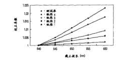
图12示出了与纸张类型和截止波长对应的数据特性;并且Figure 12 shows data characteristics corresponding to paper type and cutoff wavelength; and
图13示出了将纸张类型和光学系统的光谱特性用作参数的校正系数表格的一个例子。FIG. 13 shows an example of a correction coefficient table using the paper type and the spectral characteristics of the optical system as parameters.
具体实施方式Detailed ways
以下将参照附图,对本发明的实施例进行详细描述。Embodiments of the present invention will be described in detail below with reference to the accompanying drawings.
图1示出了按照本发明实施例的纸张处理设备1(以下简称为处理设备1)的示意图。Fig. 1 shows a schematic diagram of a paper processing device 1 (hereinafter simply referred to as processing device 1) according to an embodiment of the present invention.
处理设备1具有插入(throw-in)单元2、取出(fetching)单元4、方位(orientation)校正单元5、检查单元10(纸张鉴别设备)、剔除和收集单元6、方向改变单元7、多个分类和收集单元8a到8f和控制CPU 9。作为检查对象的多个纸张P被插入插入单元2中。取出单元4将插入的纸张P逐一取到传送路径(carrier path)3上。方位校正单元5对被取到传送路径3上的纸张P的传送方位进行校正。检查单元10对已经通过方位校正单元5的纸张P进行检查。剔除和收集单元6根据在检查单元10中的检查结果,收集已经被鉴别为不可再用的纸张P′。方向改变单元7使已经在检查单元10被鉴别为可用的纸张P的表面和下表面以及顶和底的方向一致。多个分类和收集单元8a到8f对已经通过方向改变单元7的纸张P,按照其每种类型进行分类和收集。控制CPU 9对整个处理设备1的操作进行控制。The
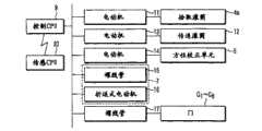
图2示出了用于对处理设备1的操作进行控制的控制系统的框图。FIG. 2 shows a block diagram of a control system for controlling the operation of the
取出电动机11、传送电动机13、方位校正电动机14、螺线管15、折返式电动机(switchback motor)16以及多个螺线管17被连接到处理设备1的控制CPU 9。取出电动机11使取出单元4的拾取滚筒4a旋转。传送电动机13使用于对被取到传送路径3上的纸张P进行传送的多个传送滚筒12旋转。方位校正电动机14使方位校正单元5运转。螺线管15对方向改变单元7的门(没有示出)进行操作。折返式电动机16使折返式滚筒(没有示出)沿着向前和向后的方向旋转。多个螺线管17分别对在传送路径3上提供的多个门G1到G6进行操作。此外,控制CPU 9被连接到上述的检查单元10的传感CPU 20。A take-
图3示出了具有经过放大的检查单元10的示意图。FIG. 3 shows a schematic illustration with an enlarged
检查单元10具有多个在传送路径3上的传送滚筒12,在传送路径3上传送纸张P。由传送电动机13使多个传送滚筒12旋转,在传送滚筒12上缠绕了多个无接头传送带(没有示出),多个传送滚筒12起本发明的传送单元的作用。The
在传送路径3上,按照图中从右侧开始的顺序,提供了透射图像传感单元21、上表面反射图像传感单元22、下表面反射图像传感单元23、磁性传感单元24、荧光传感单元25和厚度传感单元26。透射传感单元21对包括在透过纸张P的光线中的图像信息进行感测。上表面反射图像传感单元22对包括在从图中的纸张P的上表面反射的光线中的图像信息进行感测。下表面反射图像传感单元23对包括在从图中的纸张P的下表面反射的光线中的图像信息进行感测。磁性传感单元24对包括在打印在纸张P上的墨水中的磁性特性进行感测。荧光传感单元25对包括在打印在纸张P上的墨水中的荧光材料的特征量进行感测。厚度传感单元26对纸张P的厚度进行感测。此外,信号处理单元30被安装在图中的检查单元10的外壳的上部,用于对通过各个传感单元21到26检测的检测信号进行处理。On the transport path 3, in order from the right in the figure, there are provided a transmission
透射图像传感单元21、上表面反射图像传感单元22和下表面反射图像传感单元23起本发明的检测单元的作用。例如,这样的检测单元是具有起发光单元作用的卤素光源和起光接收单元作用的光电二极管阵列或电荷耦合器件(CCD)的一维图像扫描传感器。磁性传感单元24例如是一个传感器如磁头,其中,给芯材料的一次侧施加直流偏置电流,并且利用二次侧线圈对磁性材料通过磁头部分时的磁通变化进行检测。此外,荧光传感单元25例如是具有发光单元如紫外线发光灯的传感器,该传感器利用光电二极管对从介质发出的激发光进行检测。例如,对厚度传感单元26进行配置,使得纸张P被夹在传送滚筒12与夹紧滚筒26a之间,并且,由位移传感器(没有示出)等对夹紧滚筒26a或支撑夹紧滚筒的轴26b的变化进行感测,以转换为电信号。The transmission
图4举例说明了作为对包括在从纸张P反射的光线或者透过纸张P的光线中的图像信息进行感测的图像传感单元的一个例子的下表面反射图像传感单元23的示意性配置。注意,除此之外,作为内置于检查单元10中的图像传感单元,还有透射图像传感单元21和上表面反射图像传感单元22。4 illustrates a schematic configuration of a lower surface reflection
如图4所示,通过传送路径3,沿着图中的箭头T的方向传送的纸张P被光源41如卤素灯照射,并且,从纸张P反射的光线,通过波长范围限制滤波器42(以下简称为滤光器42)和光学透镜43,照射到由光电二极管阵列或电荷耦合器件(CCD)构成的光接收单元44上。在前置放大器单元45,对在光接收单元44接收的、要从光信息转换为电信号的图像信息进行信号放大。As shown in FIG. 4, through the transport path 3, the paper P transported in the direction of the arrow T in the figure is irradiated by a
图5示出了对例如在前置放大器单元45被放大的信号进行处理的上述信号处理单元30的电路配置的框图。FIG. 5 shows a block diagram of a circuit configuration of the above-described
在图5中,被连接到信号处理单元30的透射图像传感单元21、上表面反射图像传感单元22、下表面反射图像传感单元23、磁性传感单元24、荧光传感单元25和厚度传感单元26分别表示图3中示出的传感单元21到26。In FIG. 5, a transmission
在信号处理单元30中,从传感单元21到26输出的信号(感测的数据)通过模拟处理电路如运算放大器301到306,并且,对信号分量进行放大/处理。由模拟复用器31将这些六系统模拟信号分时为单系统模拟信号,此后,该信号在模数转换电路32中被转换为例如10位数字数据。In the
在本实施例中,为了使模数转换电路32成为单系统,由模拟复用器31将模拟信号分时为单系统。但是,可以按照组装系统的方式或者在硬件条件下,独立地对所有感测的信号分别进行数字化。In this embodiment, in order to make the analog-to-digital conversion circuit 32 a single system, the
然后,在预处理电路33中,将依据感测内容的预处理(例如,空间微分(space differential)、均衡等)施加于被转换为数字数据的感测数据上,并且将数据存储在数据存储单元34中。Then, in the
以微计算机为代表的用作算术处理单元的传感CPU 20从数据存储单元34中适当地读取感测的数据,并且确定纸张P的类型、方向、真/伪以及污损等级等。具体地说,传感CPU 20读取预先存储在存储器200(存储单元)中的、与纸张P的类型对应的校正系数(后面将对其进行描述),并且利用校正系数对来自图像传感单元21、22和23的输出信号进行校正。注意,传感CPU 20用作本发明的鉴别单元。The
此外,传感CPU 20将感测结果通知上级装置,即处理设备1的控制CPU 9(图2)。根据以这样的方式从检查单元10输出的关于类型、方向、真/伪以及污损等级等的信息,控制CPU 9进行控制,对门G1到G6进行开关,从而将纸张P分别传送到分类和收集单元8a到8f(以及剔除和收集单元6),分类和收集单元8a到8f将纸张收集于其中。例如,在控制CPU 9的控制下,被传感CPU 20确定为污损等级达到不能再使用程度的纸张P被剔除到剔除和收集单元6。In addition, the
同时,传感CPU 20以如下方式确定纸张P的污损等级。即,传感CPU 20整体上进行确定,不仅依据图像数据确定纸张P的污染情况、打印部分的磨薄点,而且对皱褶、折角以及孔等进行鉴别,并且利用厚度传感器对带和杂质进行感测,并且,输出最终确定的结果。具体地说,当确定纸张P的污染情况时,使用利用上述光学系统的反射图像和透射图像。详细地说,在这种情况下,传感CPU 20利用由透射图像传感单元21、上表面反射图像传感单元22和下表面反射图像传感单元23感测的图像数据,鉴别纸张P的污染情况。Meanwhile, the
即,当确定纸张P的污染情况时,推荐使用与人眼接近的光学系统。如果人眼看到的污染情况与通过光学系统获得的图像信息之间的相互关系清楚,则可以确定与人的感觉等同的污染。That is, when determining the contamination condition of the paper P, it is recommended to use an optical system close to the human eye. If the correlation between the pollution seen by the human eye and the image information obtained by the optical system is clear, the pollution equivalent to the human perception can be determined.
注意,为了鉴别纸张P的真/伪,各个图像传感单元21、22和23的光学系统具有对不能被人眼看到的紫外线区或红外线区中的图像进行感测的功能,而本实施例被完全设计为对可见图像区(红、绿、蓝三原色的区域)中的图像进行感测。但是,依据构成光学系统的部件的特性,即使在紫外线区或红外线区中,也可以得到与后面描述的效果相同的效果。因此,波长区域不限于可见区。Note that in order to identify the authenticity of the paper P, the optical systems of the respective
作为上述图像传感单元的一个例子,图6示出了图4中描述的下表面反射图像传感单元23的各个组件(包括纸张P)的光谱特性。具体地说,图6示出了作为光接收单元44的一个例子的彩色CCD、作为滤光器42的一个例子的红外截止滤波器、作为光源41的一个例子的卤素发光器以及纸张P的相应的光谱特性的一个例子。在该图中,横坐标表示可见区中的波长,纵坐标表示彩色CCD传感器的光谱灵敏度特性、红外线截止滤波器的光谱透射特性、卤素发光器的光谱发射量特性以及纸张P的光谱反射特性。As an example of the above-mentioned image sensing unit, FIG. 6 shows spectral characteristics of various components (including paper P) of the lower surface reflection
由于在红色传感器的最大值并且在红外线区内的最大值(没有示出),分别对彩色CCD传感器和卤素发光器进行规范化,因此各个特性值不是绝对值。除此之外,光学透镜43还具有在可见区内大致平坦的光谱透射特性。为此,本实施例没有对此加以考虑。但是,在实际产品开发过程中,有可能在设计中考虑光学透镜43。The respective characteristic values are not absolute values due to the maximum value in the red sensor and the maximum value in the infrared region (not shown), respectively, normalized for the color CCD sensor and the halogen light emitter. In addition to this, the optical lens 43 also has a substantially flat spectral transmission characteristic in the visible region. For this reason, this embodiment does not take this into account. However, during actual product development, it is possible to consider the optical lens 43 in the design.
以下将参照图6的光谱特性,对在下表面反射图像传感单元23中获得纸张P的彩色图像数据的处理进行描述。The process of obtaining color image data of the paper sheet P in the lower surface reflection
如图4所示,纸张P被传送并且被来自光源41的光线照射,通过滤光器42和光学透镜43,在CCD光接收单元44(红、绿、蓝)接收从纸张P反射的光。当在光接收单元44中对反射光进行光电转换时,作为电信号获得的红、绿、蓝各个信号的电压电平被表达为图6中示出的各个分量的光谱特性的综合值。更详细地说,当将各个分量的波长的光谱特性按照如下示出时:As shown in FIG. 4 , the paper P is transported and irradiated with light from a
CCD传感器(蓝)的光谱灵敏度特性RBi(i:400到700nm)Spectral Sensitivity Characteristics of CCD Sensor (Blue) RBi (i: 400 to 700nm)
CCD传感器(绿)的光谱灵敏度特性RGi(i:400到700nm)Spectral sensitivity characteristic RGi (i: 400 to 700nm) of CCD sensor (green)
CCD传感器(红)的光谱灵敏度特性RRi(i:400到700nm)Spectral Sensitivity Characteristics of CCD Sensor (Red) RRi (i: 400 to 700nm)
滤光器的光谱透射特性Fi(i:400到700nm)Spectral transmission characteristic Fi of the filter (i: 400 to 700nm)
卤素发光器的光谱发射量特性Li(i:400到700nm)Spectral emission characteristics of halogen emitters Li (i: 400 to 700nm)
纸张P的光谱反射特性Oi(i:400到700nm),Spectral reflection characteristic Oi of paper P (i: 400 to 700nm),
则RGB传感器的输出可以表达为:Then the output of the RGB sensor can be expressed as:
(1)CCD传感器(蓝)的输出Db=∑i=400到700Rbi×Fi×Li×Oi(1) Output of CCD sensor (blue) Db=∑i=400 to 700Rbi×Fi×Li×Oi
(2)CCD传感器(绿)的输出Dg=∑i=400到700RGi×Fi×Li×Oi(2) Output Dg of CCD sensor (green)=∑i=400 to 700RGi×Fi×Li×Oi
(3)CCD传感器(红)的输出Dr=∑i=400到700RRi×Fi×Li×Oi(3) Output Dr of CCD sensor (red)=∑i=400 to 700RRi×Fi×Li×Oi
式中,上述的Db、Dg和Dr只是三个彩色信号的电平的比值。实际上,根据模拟灯的增益、各个分量的绝对灵敏度和绝对发射量,确定输出电压。In the formula, the above-mentioned Db, Dg and Dr are only the ratios of the levels of the three color signals. In practice, the output voltage is determined from the gain of the simulated lamp, the absolute sensitivity of the individual components and the absolute emission.
当改变作为测量对象的纸张P的类型时,如果纸张P的光谱反射特性,即上式中的Oi变化,则可以发现纸张P的RGB传感器输出。此外,如上所述,当考虑光学透镜43的光谱透射特性(Ti)时,给上式添加“×Ti”即可。When the type of paper P that is the object of measurement is changed, the RGB sensor output of paper P can be found if the spectral reflectance characteristic of paper P, ie, Oi in the above formula, changes. In addition, as described above, when considering the spectral transmission characteristic (Ti) of the optical lens 43, it is only necessary to add "×Ti" to the above formula.
图7示出了当实际读取一百张纸张P的未打印部分时,RGB信号的电平的频率分布(直方图)的一个例子。图中的横坐标用于从传感器获得的信号电压按照100级表达的数值,值越接近100,则来自传感器的输出越大。纵坐标示出了在相应的电平下出现的频率。这里,注意力集中在,例如,来自红色传感器的输出,其分布为:FIG. 7 shows an example of the frequency distribution (histogram) of the levels of RGB signals when unprinted portions of one hundred sheets of paper P are actually read. The abscissa in the figure is for the value expressed in 100 steps of the signal voltage obtained from the sensor, and the closer the value is to 100, the larger the output from the sensor. The ordinate shows the frequency occurring at the corresponding level. Here, attention is focused on, for example, the output from the red sensor, whose distribution is:
在信号电平86;18次At
在信号电平87;20次At signal level 87; 20 times
在信号电平88;17次At signal level 88; 17 times
在信号电平89;13次At signal level 89; 13 times
并且,很明显,来自纸张P的红色信号的平均信号电平(信号电平中的峰值)约为87。同样,很明显,在蓝色信号当中,分布的中心是平均信号电平(峰值)约为44,在绿色信号当中,平均信号电平(峰值)约为71。And, it is apparent that the average signal level (peak in signal level) of the red signal from the paper P is about 87. Also, it is clear that the distribution is centered at an average signal level (peak) of approximately 44 in the blue signal and approximately 71 in the green signal.
以这样的方式,在图7中举例说明的直方图示出了这样获得的数值,其中,通过内置于特定类型的处理设备1的检查单元10中的图像传感单元,对一百张纸张P进行感测。但是,当利用多个处理设备1对它们进行测量时,在某些情况下,在信号电平的频率分布方面引起偏移。即,颜色输出的频率分布可能随图像传感单元中的光学系统的特性方面的差异而变化。图8示出了其中的一个例子。In this way, the histogram illustrated in FIG. 7 shows the values obtained for one hundred sheets of paper P for sensing. However, when they are measured with a plurality of
图8示出了从内置于三个处理设备1的检查单元10中的图像传感单元输出的重叠在一起的红色信号的直方图,信号电平的峰值分别为:Fig. 8 shows the histograms of overlapping red signals output from the image sensing units built in the
在设备1中;信号电平90In
在设备2中;信号电平87In
在设备3中;信号电平84In device 3; signal level 84
很明显,在这三个设备当中,最大电平差为6。Obviously, among the three devices, the maximum level difference is 6.
通常,利用参考介质,例如,白色陶瓷板等,对在处理设备1的检查单元10中使用的光学系统进行对于RGB中的每一个的、包括所有光学部件的特性的灵敏度校正(黑斑校正)。为此,必须不引起设备之间的差异。但是,在某些情况下,即使使用了白色参考板,也不能彻底校正光学部件的光谱特性之间的微小差异。因此,使用了一种方法,其中,在各个设备中收集作为对象的纸张P的数据,并且通过寻找各个纸张P的分布中心进行校正。例如,假设设备1是参考设备。通过进行运算,对设备之间的差别进行校正:Usually, the optical system used in the
对于来自设备2的红色信号,校正后的信号电平=校正前的信号电平×90/87,并且For the red signal from
以同样方式,通过进行下述运算,对设备之间的差别进行校正:In the same way, corrections are made for differences between devices by performing the following operations:
对于来自设备3的红色信号,校正后的信号电平=校正前的信号电平×90/84。For the red signal from device 3, the signal level after correction=the signal level before correction×90/84.
图9示出了校正之后,在各个设备中的红色信号电平的频率分布。因此,很明显,三个设备中的信号电平的峰值被校正成大致彼此重叠。但是,实际上,每当作为对象的纸张P的类型改变时,都需要进行上述的校正。这是由各个纸张P的光谱反射特性方面的差异引起的。FIG. 9 shows the frequency distribution of the red signal level in each device after correction. Therefore, it is apparent that the peaks of the signal levels in the three devices are corrected to substantially overlap each other. However, in practice, the above-mentioned correction is required every time the type of paper P to be the object is changed. This is caused by the difference in the spectral reflectance characteristics of the individual paper sheets P.
图10示出了在某两个处理设备(设备1和设备2)中,纸张1和纸张2的频率分布的例子。在本例中,各个信号电平的频率分布的峰值如下:Fig. 10 shows an example of the frequency distribution of
在设备1中,纸张1;信号电平90In
在设备2中,纸张1;信号电平87In
在设备1中,纸张2;信号电平75In
在设备2中,纸张2;信号电平65In
假设设备1是参考设备,则各个纸张的校正系数如下。Assuming that
纸张1:90/87=1.034Sheet 1: 90/87 = 1.034
纸张2:75/65=1.154Paper 2: 75/65 = 1.154
因此,很明显,根据纸张P的类型,校正系数彼此完全不同。Therefore, it is obvious that the correction coefficients are completely different from each other depending on the type of paper P.
当根据纸张P的类型,校正系数之间没有差异时,例如,只将纸张1馈送到设备中,将校正系数(1.034)存储在设备中,则对其它类型的纸张P应用校正系数就足够了。实际上,在许多情况下,与图10的例子中相同,产生取决于纸张P的类型的差异。即,为了进行高精度个别校正,需要将作为检查对象的所有类型的纸张P馈送到处理设备1中的每个设备中,收集其数据,并且为每种类型的纸张计算校正系数,由此存储用于每个设备体的校正系数,在许多情况下,从管理设备体的观点出发,这将是很复杂的。此外,当由于设备故障等原因导致对图像传感单元中的整个光学系统或构成光学系统的某些部件进行更换时,每次都需要以与上述方式相同的方式,利用纸张P进行校正,这样做成本巨大,并且占用大量维修时间。When there is no difference between the correction coefficients depending on the type of paper P, for example, only
另外,将对在设备体之间引起信号电平方面的差异的原因加以考虑。In addition, consideration will be given to the cause of the difference in signal level between equipment bodies.
如上所述,利用构成光学系统的光学部件(组件)的光谱特性的综合值,可以得到来自传感器的输出信号的颜色比例。因此,当即使在多个光学部件当中,只有一个部件的光谱特性不稳定时,在由不同设备体对相同类型的纸张P进行检查的情况下,也会使得检查结果彼此不同。As described above, the color scale of the output signal from the sensor can be obtained using the integrated value of the spectral characteristics of the optical parts (packages) constituting the optical system. Therefore, when the spectral characteristic of only one component is unstable even among a plurality of optical components, in the case of inspection of the same type of paper P by different apparatus bodies, the inspection results are made to differ from each other.
图11举例说明具有不同光谱透射特性的两个滤光器42的特性。在图10中示出了由于滤光器42的特性方面的差异而导致的红色信号输出方面的差别。即,滤光器1被用在设备1中,而滤光器2被用在设备2中。Fig. 11 illustrates the characteristics of two filters 42 having different spectral transmission characteristics. The difference in red signal output due to the difference in characteristics of the optical filter 42 is shown in FIG. 10 . That is,
在使用滤光器2的设备2中,两种类型的纸张之间的信号电平峰值方面的差异大于使用滤光器1的设备1在这方面的差异。这是由纸张1和纸张2在滤光器的截止波长(650nm)附近的波长特性的差异导致的。纸张1表现出大致平坦的反射特性。但是,在纸张2中,波长越长,反射率越高。更详细地说,两个设备中的滤光器42的截止波长方面的差异越大,两个设备之间的输出差异越大。In the
图12示出了五种类型的纸张P在滤光器42的截止波长附近(640到660nm)的光谱反射特性的一个例子。如上所述,已经利用通用参考介质,例如,白色陶瓷板等,对光学系统进行了灵敏度校正。在可见区中,参考板的波长特性是大致平坦的,并且,图12的纸张1具有与参考板大致相同的平坦度。FIG. 12 shows an example of spectral reflectance characteristics of five types of paper P in the vicinity of the cutoff wavelength (640 to 660 nm) of the optical filter 42 . Sensitivity correction of the optical system has been performed using a common reference medium, eg, a white ceramic plate, etc., as described above. In the visible region, the wavelength characteristic of the reference plate is approximately flat, and the
即,纸张1受滤光器42的截止波长变化的影响较小。随纸张2、3、4递进,波长特性向右上方倾斜,因而,纸张更容易受截止波长变化的影响。That is, the
例如,假设在两个设备中,设备1的截止波长为660nm,而设备2的截止波长为640nm。根据白色参考板,对于纸张1,在两个设备中可以得到大致相同的输出值。但是,对于纸张5,具有较长截止波长的设备1表现出较高的值。即,当由利用具有相同特性的参考板进行过校正的两个设备分别读取相同的纸张时,由滤光器的光谱灵敏度方面的差异导致了数据值彼此不同。具体地说,在许多情况下,当根据图像数据对纸张P是否被写过或被损坏进行鉴别时,由于设备体之间的差异导致的性能下降成为问题。For example, assume that among two devices,
因此,对本实施例这样进行设计,使得能够在不对光学系统的详细特性进行测量并且不为每种类型的纸张P准备校正系数的情况下,高度精确并且极其容易地对设备体之间的性能差别进行校正。在下文中,将对这个过程进行描述。对其的描述是这样的,即,用滤光器的特性(截止波长)方面的差别代替设备体之间性能方面的差别。Therefore, the present embodiment is so designed that it is possible to highly accurately and extremely easily analyze the difference in performance between the apparatus bodies without measuring the detailed characteristics of the optical system and without preparing correction coefficients for each type of paper P. Make corrections. Hereinafter, this process will be described. Its description is such that the difference in performance between device bodies is replaced by the difference in characteristics (cutoff wavelength) of the optical filter.
首先,利用测量仪器如分光光度计对作为检查对象的纸张P的光谱反射特性进行测量。相似地,为了对设备体之间的特性方面的差异进行模拟,准备具有不同特性的两种滤光器,并且利用测量仪器对各个滤光器的光谱透射特性进行测量。假如被测量的两种滤光器是制造所引起的差别的上限和下限,则更有效。First, the spectral reflection characteristics of the paper P as the inspection object are measured with a measuring instrument such as a spectrophotometer. Similarly, in order to simulate differences in characteristics between device bodies, two kinds of filters having different characteristics were prepared, and the spectral transmittance characteristics of the respective filters were measured with a measuring instrument. It is more effective if the two filters being measured are the upper and lower limits of manufacturing-induced differences.
接着,需要对光接收单元44和光源41的传感器的光谱特性进行测量。但是,由于通常在二者之间没有绝对标准,并且测量本身有困难,因此从设备制造商等处得到参考光谱特性数据。当能够以任何途径收集到数据时,可以使用这些数据。另外,当可以将滤光器42和纸张P的光谱特性获得为数据时,可以使用这些数据。Next, it is necessary to measure the spectral characteristics of the light receiving unit 44 and the sensor of the
接着,通过插值等方法,获得滤光器42的截止波长处于滤光器42的特性变化范围内时的光谱特性。这里,利用上述公式,获得考虑了光源41、纸张P、滤光器42以及光敏传感器44的综合值(实际上,是每个波长的乘积的和)。本实施例中的参数是滤光器42的截止波长和纸张P的类型。即,为每种类型的纸张P获得取决于截止波长方面的差异的校正系数,并且,准备校正系数表格。图13示出了用于每种类型的纸张P的、截止波长与校正系数之间的关系的例子。在图13中示出的曲线中,很明显,对于所有类型的纸张P,在640nm的基准上,截止波长越长,校正系数越大。另外,很明显,在截止波长附近的光谱特性与白色参考板越不同,校正系数越大。Next, by means of interpolation or the like, the spectral characteristics when the cutoff wavelength of the optical filter 42 is within the characteristic variation range of the optical filter 42 are obtained. Here, using the above formula, an integrated value (actually, a sum of products of each wavelength) in consideration of the
接着,准备校正系数大于具有最大校正系数的纸张(在本例中为纸张4)的测试券(ticket),并且,以相同方式对其校正系数进行计算以添加到上述的图13的校正表格中。此外,将测试券馈送到作为校正标准的设备体(设备1)中,并且记录来自参考设备的输出值(Torg)。预先准备到此结束。Next, a test ticket having a correction coefficient larger than that of the paper (paper 4 in this example) having the largest correction coefficient is prepared, and its correction coefficient is calculated in the same manner to be added to the above-mentioned correction table of FIG. 13 . In addition, test coupons are fed into the device body (device 1) as a calibration standard, and the output value (Torg) from the reference device is recorded. This concludes the advance preparation.
在下文中,对这样的方法进行描述,通过该方法,利用上述的校正表格,对参考设备以外的其它设备进行校正,使得其它设备具有与参考设备的特性大致相同的特性。Hereinafter, a method is described by which, using the above-mentioned correction table, correction is performed on other devices than the reference device so that the other devices have substantially the same characteristics as those of the reference device.
将上述的测试券馈送到特性必须被校正的设备体(这里为设备2)中,并且,以与参考设备相同的方式对输出值(td1)进行测量。然后,获得Td1/Torg,在校正表格上指定了各种纸张关于测试券的比值的校正系数,并且将这些校正系数存储在设备2的内部存储装置中。即,对测试券的关于参考设备的输出的比值进行计算,并且,通过将运算结果反映到所有类型的纸张上,准备用于设备2的校正表格。The test coupons described above are fed into the device body (here, device 2) whose characteristics must be corrected, and the output value (td1) is measured in the same manner as the reference device. Then, Td1/Torg is obtained, the correction coefficients of the ratios of various paper sheets with respect to the test coupons are specified on the correction table, and these correction coefficients are stored in the internal storage means of the
当设备2实际运行时,根据作为处理对象的纸张P的类型,读取预先在校正表格中准备的上述校正系数,并且,利用读取的校正系数对从实际纸张P读取的图像数据进行校正,这使得能够提供与参考设备的校正系数大致相同的校正参考。When the
如上所述,按照本实施例,通过将测试券馈送到参考设备中,准备好所有类型纸张P的校正系数,并且,将测试券馈送到另一个设备体中,以便将其输出电平与参考设备的输出电平进行比较,从而根据其间的比值,对上述的校正系数进行调整,使之成为用于设备体的校正参考。因此,按照本实施例,不必像现有技术中那样,对校正参考与参考设备的校正参考一致的另一个设备中的图像传感单元的光学系统的详细特性进行测量。因此,不必为每种纸张准备校正系数,这使得能够比较容易地准备其它设备体的校正参考,并且,能够提供高度精确的校正参考。As described above, according to the present embodiment, correction coefficients for all types of paper P are prepared by feeding the test coupons into the reference device, and the test coupons are fed into another device body to compare their output levels with the reference device. The output levels of the equipment are compared, so that the above-mentioned correction coefficients are adjusted according to the ratio between them, making it a calibration reference for the equipment body. Therefore, according to the present embodiment, it is not necessary to measure the detailed characteristics of the optical system of the image sensing unit in another device whose correction reference coincides with that of the reference device, as in the prior art. Therefore, it is not necessary to prepare correction coefficients for each kind of paper, which makes it relatively easy to prepare correction references for other apparatus bodies, and enables highly accurate correction references to be provided.
对于本领域技术人员来说,另外的优点和修改很容易出现。因此,在其更广的方面,本发明不限于这里所示出和描述的特定细节和典型实施例。因此,在不脱离由所附权利要求以及它们的等价物所限定的一般发明概念的精神或范围的情况下,可以进行各种修改。Additional advantages and modifications will readily appear to those skilled in the art. Therefore, the invention in its broader aspects is not limited to the specific details and typical embodiments shown and described herein. Accordingly, various modifications may be made without departing from the spirit or scope of the general inventive concept as defined by the appended claims and their equivalents.
例如,上述实施例已经对滤光器42的截止波长不同时的校正方法进行了描述。但是,本发明不限于改变滤光器42的特性的情况,并且,可以将本发明应用于光敏元件44的颜色滤波器(没有示出)的光谱灵敏度特性不同的情况、由于色温特性方面的差异而导致的光源41的光谱发射量特性不同的情况、或者光学透镜43的光谱透射特性不同的情况,并且,可以实现相同的校正方法。For example, the above embodiments have described the correction method when the cutoff wavelengths of the optical filters 42 are different. However, the present invention is not limited to the case of changing the characteristics of the optical filter 42, and the present invention can be applied to the case where the spectral sensitivity characteristics of color filters (not shown) of the photosensitive element 44 are different, due to the difference in color temperature characteristics However, when the spectral emission characteristic of the
此外,在上述实施例中,利用反射图像获得作为鉴别纸张P的污染情况的基础的图像数据。但是,本发明不限于此,例如,利用纸张P的透射图像也能够得到同样效果。Furthermore, in the above-described embodiments, image data as a basis for discriminating the contamination condition of the paper sheet P is obtained using the reflection image. However, the present invention is not limited thereto. For example, the same effect can be obtained by using the transmission image of the paper P. FIG.
本实施例还对将一种类型的测试券用作用于测试的介质的情况进行了描述。但是,本发明不限于此,例如,可以使用具有与作为检查对象的纸张P的特性大致相同的特性的测试券。此外,测试券的类型不限于一种类型,而是可以使用多种类型的测试券,并且,可以为每种纸张P准备多种类型的测试券。此外,在上述实施例中,使用了灵敏度比作为检查对象的多种纸张P的灵敏度高的测试券。但是,不是必需使用灵敏度比作为检查对象的纸张P的灵敏度高的测试券。This embodiment also describes the case where one type of test coupon is used as the medium for the test. However, the present invention is not limited thereto, and for example, a test coupon having substantially the same characteristics as the paper P to be inspected may be used. Furthermore, the type of test coupons is not limited to one type, but multiple types of test coupons may be used, and multiple types of test coupons may be prepared for each paper P. Furthermore, in the above-described embodiments, test coupons having a higher sensitivity than that of the plurality of paper sheets P to be inspected are used. However, it is not necessary to use a test coupon having a higher sensitivity than the paper P to be inspected.
此外,在上述实施例中使用了测试券。例如,假设利用作为对象的纸张当中的、受波长特性影响最大的纸张P本身进行校正,则可以得到相同效果。In addition, test coupons are used in the above-described embodiments. For example, assuming that correction is performed using the paper P itself, which is most affected by the wavelength characteristics, among the target papers, the same effect can be obtained.
此外,已经对将用作校正参考的校正系数准备为校正表格的情况进行了描述。但是,在实际操作时,可以不准备校正表格,而是每当确定一种类型的纸张P时,改变内部的算术表达式,并且,通过在每种情况下利用算术表达式进行计算,可以准备好校正系数。因此,可以得到相同效果。Furthermore, description has been made on the case where correction coefficients used as correction references are prepared as a correction table. However, in actual operation, instead of preparing a correction table, an internal arithmetic expression is changed every time a type of paper P is determined, and by performing calculation using the arithmetic expression in each case, it is possible to prepare Good correction factor. Therefore, the same effect can be obtained.
Claims (21)
Applications Claiming Priority (3)
| Application Number | Priority Date | Filing Date | Title |
|---|---|---|---|
| JP2005365061AJP2007172059A (en) | 2005-12-19 | 2005-12-19 | Paper sheet discriminating apparatus and paper sheet processing apparatus |
| JP2005-365061 | 2005-12-19 | ||
| JP2005365061 | 2005-12-19 |
Publications (2)
| Publication Number | Publication Date |
|---|---|
| CN1987935A CN1987935A (en) | 2007-06-27 |
| CN1987935Btrue CN1987935B (en) | 2010-06-09 |
Family
ID=37779970
Family Applications (1)
| Application Number | Title | Priority Date | Filing Date |
|---|---|---|---|
| CN2006101685618AActiveCN1987935B (en) | 2005-12-19 | 2006-12-19 | Paper identification device, paper processing device, and paper identification method |
Country Status (5)
| Country | Link |
|---|---|
| US (1) | US20070139720A1 (en) |
| EP (1) | EP1798693A1 (en) |
| JP (1) | JP2007172059A (en) |
| KR (1) | KR20070065228A (en) |
| CN (1) | CN1987935B (en) |
Cited By (2)
| Publication number | Priority date | Publication date | Assignee | Title |
|---|---|---|---|---|
| CN102819888A (en)* | 2011-06-07 | 2012-12-12 | 光荣株式会社 | Paper sheet handling machine and paper sheet handling method |
| US12259326B2 (en) | 2021-10-20 | 2025-03-25 | Arizona Board Of Regents On Behalf Of Arizona State University | Dry fluorescence calibration technique |
Families Citing this family (15)
| Publication number | Priority date | Publication date | Assignee | Title |
|---|---|---|---|---|
| JP5174513B2 (en)* | 2008-04-03 | 2013-04-03 | グローリー株式会社 | Paper sheet stain detection apparatus and stain detection method |
| JP2010277252A (en)* | 2009-05-27 | 2010-12-09 | Toshiba Corp | Paper sheet discrimination device |
| DE102009058439A1 (en)* | 2009-12-16 | 2011-06-22 | Giesecke & Devrient GmbH, 81677 | Method for checking value documents |
| DE102011077895A1 (en)* | 2011-06-21 | 2012-12-27 | Bundesdruckerei Gmbh | Method and device for creating a document reference data record based on a document |
| CN102262794A (en)* | 2011-08-10 | 2011-11-30 | 深圳市怡化电脑有限公司 | Intelligent magnetic sensor module for detection of paper money |
| JP2013214129A (en)* | 2012-03-30 | 2013-10-17 | Toshiba Corp | Ticket processor and ticket processing method |
| CN103679914B (en)* | 2013-12-12 | 2016-06-15 | 广州广电运通金融电子股份有限公司 | A kind of banknote recognition methods based on thickness signal identification and device |
| CN103617671B (en)* | 2013-12-12 | 2016-08-17 | 广州广电运通金融电子股份有限公司 | The recognition methods of a kind of thickness abnormity banknote and system |
| CN103942881A (en)* | 2014-04-11 | 2014-07-23 | 立德高科(北京)数码科技有限责任公司 | Equipment and method for carrying out batch anti-fake detection on presswork with raster graphics |
| CN105093353B (en)* | 2014-05-04 | 2018-02-02 | 山东新北洋信息技术股份有限公司 | The bearing calibration of sensor and media processing device in media processing device |
| CN104438099A (en)* | 2014-09-22 | 2015-03-25 | 天津长荣印刷设备股份有限公司 | Large waste removing device and operating method thereof |
| KR101539604B1 (en)* | 2014-12-10 | 2015-07-28 | (주)비티비코리아 | Automated Teller Machine and method for detecting counterfeit thereof |
| CN107437295B (en)* | 2016-05-26 | 2020-08-21 | 山东新北洋信息技术股份有限公司 | Method and device for correcting scanning module of paper money processing device |
| JP6811140B2 (en)* | 2017-04-12 | 2021-01-13 | 日本金銭機械株式会社 | Paper leaf discrimination device and paper leaf discrimination system |
| CN107175923A (en)* | 2017-05-08 | 2017-09-19 | 陕西赛富网络科技有限责任公司 | Detect method, device and the printer of print paper material |
Citations (2)
| Publication number | Priority date | Publication date | Assignee | Title |
|---|---|---|---|---|
| CN1639741A (en)* | 2002-08-30 | 2005-07-13 | 富士通先端科技株式会社 | Paper sheets characteristic detection device and paper sheets characteristic detection method |
| CN1682250A (en)* | 2002-09-17 | 2005-10-12 | 德国捷德有限公司 | Method and device for checking value documents |
Family Cites Families (17)
| Publication number | Priority date | Publication date | Assignee | Title |
|---|---|---|---|---|
| US4795281A (en)* | 1984-11-30 | 1989-01-03 | Tohoku Ricoh Co., Ltd. | Self-correcting printer-verifier |
| JP2660568B2 (en)* | 1989-01-12 | 1997-10-08 | 富士写真フイルム株式会社 | Restoring improperly exposed images |
| US6199480B1 (en)* | 1992-06-06 | 2001-03-13 | Heideiberger Druckmaschinen | Arrangement for determining register deviations of a multicolor rotary printing machine |
| EP0651352A1 (en)* | 1993-10-27 | 1995-05-03 | Toshiba Engineering Corporation | Method and apparatus of inspecting surface irregularity of an object article |
| US6092943A (en)* | 1997-06-11 | 2000-07-25 | Brother Kogyo Kabushiki Kaisha | Apparatus and method for measuring printing paper quantity and warning printing part exchange time |
| JP3953144B2 (en)* | 1997-07-16 | 2007-08-08 | オリンパス株式会社 | Code image quality inspection system |
| JP2001041899A (en)* | 1999-07-27 | 2001-02-16 | Toshiba Corp | Soil condition identification device for paper sheets |
| JP3839207B2 (en)* | 2000-01-14 | 2006-11-01 | グローリー工業株式会社 | Paper sheet identification device |
| US7103206B2 (en)* | 2000-02-08 | 2006-09-05 | Cummins-Allison Corp. | Method and apparatus for detecting doubled bills in a currency handling device |
| DE60231752D1 (en)* | 2001-07-12 | 2009-05-07 | Do Labs | METHOD AND SYSTEM FOR IMPLEMENTING AN IMAGE FROM A DIGITAL IMAGE |
| JP5193409B2 (en)* | 2001-09-21 | 2013-05-08 | 株式会社東芝 | Inspection method and test medium for paper sheet processing apparatus and paper sheet processing apparatus |
| DE10151854A1 (en)* | 2001-10-24 | 2003-05-08 | Giesecke & Devrient Gmbh | Security document processing device, method for functional testing, adjustment and / or calibration of the security document processing device and test media for performing the method |
| EP1324278A1 (en)* | 2001-12-28 | 2003-07-02 | Mars Incorporated | Calibration of currency validators |
| JP2004157701A (en)* | 2002-11-06 | 2004-06-03 | Hitachi Ltd | Optical detector |
| JP2004326547A (en)* | 2003-04-25 | 2004-11-18 | Nippon Conlux Co Ltd | Method and apparatus for identifying sheet of paper |
| JP4634073B2 (en)* | 2004-06-29 | 2011-02-16 | マミヤ・オーピー株式会社 | Paper sheet identification device and identification method |
| JP4529828B2 (en)* | 2005-07-19 | 2010-08-25 | 富士ゼロックス株式会社 | Document falsification prevention device |
- 2005
- 2005-12-19JPJP2005365061Apatent/JP2007172059A/enactivePending
- 2006
- 2006-12-06EPEP06025264Apatent/EP1798693A1/ennot_activeCeased
- 2006-12-18KRKR1020060129273Apatent/KR20070065228A/ennot_activeCeased
- 2006-12-18USUS11/640,211patent/US20070139720A1/ennot_activeAbandoned
- 2006-12-19CNCN2006101685618Apatent/CN1987935B/enactiveActive
Patent Citations (2)
| Publication number | Priority date | Publication date | Assignee | Title |
|---|---|---|---|---|
| CN1639741A (en)* | 2002-08-30 | 2005-07-13 | 富士通先端科技株式会社 | Paper sheets characteristic detection device and paper sheets characteristic detection method |
| CN1682250A (en)* | 2002-09-17 | 2005-10-12 | 德国捷德有限公司 | Method and device for checking value documents |
Non-Patent Citations (1)
| Title |
|---|
| JP特开2003-99837A 2003.04.04 |
Cited By (3)
| Publication number | Priority date | Publication date | Assignee | Title |
|---|---|---|---|---|
| CN102819888A (en)* | 2011-06-07 | 2012-12-12 | 光荣株式会社 | Paper sheet handling machine and paper sheet handling method |
| CN102819888B (en)* | 2011-06-07 | 2015-05-20 | 光荣株式会社 | Paper sheet handling machine and paper sheet handling method |
| US12259326B2 (en) | 2021-10-20 | 2025-03-25 | Arizona Board Of Regents On Behalf Of Arizona State University | Dry fluorescence calibration technique |
Also Published As
| Publication number | Publication date |
|---|---|
| KR20070065228A (en) | 2007-06-22 |
| EP1798693A1 (en) | 2007-06-20 |
| US20070139720A1 (en) | 2007-06-21 |
| CN1987935A (en) | 2007-06-27 |
| JP2007172059A (en) | 2007-07-05 |
Similar Documents
| Publication | Publication Date | Title |
|---|---|---|
| CN1987935B (en) | Paper identification device, paper processing device, and paper identification method | |
| KR101297702B1 (en) | Improved fake currency detector using integrated transmission and reflective spectral response | |
| KR101333278B1 (en) | Improved fake currency detector using visual and reflective spectral response | |
| RU2481637C2 (en) | Illumination alternation | |
| RU2597505C2 (en) | Device and method for processing banknotes | |
| EP1066602B1 (en) | Methods and apparatus for monitoring articles | |
| JP2001126107A (en) | Method and device for identifying paper sheets | |
| JPH02297049A (en) | Tester for sheet-shaped member | |
| KR20000016335A (en) | Bank note validator | |
| JP7688984B2 (en) | Paper sheet identification device and paper sheet identification method | |
| US7519213B2 (en) | Optical double feed detection | |
| WO2011036748A1 (en) | Paper sheet identification device and paper sheet identification method | |
| US20070145118A1 (en) | Sheet processing method and sheet processing apparatus | |
| JP2020154566A (en) | Paper leaf processing equipment and paper leaf processing method | |
| JP2004302836A (en) | Device and method for discriminating sheet | |
| JP2010039897A (en) | Light detection device and paper sheet processor | |
| JP2011258029A (en) | Sheets discrimination method, sheets discrimination device and normal/defective discrimination learning method | |
| JP2004326548A (en) | Method and apparatus for identifying sheet of paper | |
| JP2001074659A (en) | Fluorescence detector for paper sheets | |
| JP4650366B2 (en) | Bill recognition device | |
| JP2010033176A (en) | Detection device for fluorescence/afterglow, and paper sheet processing unit | |
| CN105844780A (en) | Paper discrimination apparatus, correction information setting method and paper discrimination method | |
| JP7195831B2 (en) | Paper sheet handling equipment and paper sheet handling system | |
| JP7508400B2 (en) | DOUBLE FEED DETECTION DEVICE AND METHOD | |
| JP7715661B2 (en) | Paper sheet identification device, paper sheet processing device, and paper sheet identification method |
Legal Events
| Date | Code | Title | Description |
|---|---|---|---|
| C06 | Publication | ||
| PB01 | Publication | ||
| C10 | Entry into substantive examination | ||
| SE01 | Entry into force of request for substantive examination | ||
| C14 | Grant of patent or utility model | ||
| GR01 | Patent grant |