CN1985068A - Temperature limited heaters with thermally conductive fluid used to heat subsurface formations - Google Patents
Temperature limited heaters with thermally conductive fluid used to heat subsurface formationsDownload PDFInfo
- Publication number
- CN1985068A CN1985068ACNA2005800165959ACN200580016595ACN1985068ACN 1985068 ACN1985068 ACN 1985068ACN A2005800165959 ACNA2005800165959 ACN A2005800165959ACN 200580016595 ACN200580016595 ACN 200580016595ACN 1985068 ACN1985068 ACN 1985068A
- Authority
- CN
- China
- Prior art keywords
- temperature
- heater
- conductor
- ferromagnetic
- formation
- Prior art date
- Legal status (The legal status is an assumption and is not a legal conclusion. Google has not performed a legal analysis and makes no representation as to the accuracy of the status listed.)
- Pending
Links
- 239000012530fluidSubstances0.000titleclaimsabstractdescription73
- 230000015572biosynthetic processEffects0.000titleclaimsdescription170
- 238000005755formation reactionMethods0.000titleclaimsdescription162
- 239000004020conductorSubstances0.000claimsabstractdescription327
- 239000003302ferromagnetic materialSubstances0.000claimsabstractdescription54
- 239000000463materialSubstances0.000claimsdescription51
- 239000001307heliumSubstances0.000claimsdescription29
- 229910052734heliumInorganic materials0.000claimsdescription29
- SWQJXJOGLNCZEY-UHFFFAOYSA-Nhelium atomChemical compound[He]SWQJXJOGLNCZEY-UHFFFAOYSA-N0.000claimsdescription29
- 238000000034methodMethods0.000claimsdescription17
- 229910052739hydrogenInorganic materials0.000claimsdescription9
- 239000001257hydrogenSubstances0.000claimsdescription8
- UFHFLCQGNIYNRP-UHFFFAOYSA-NHydrogenChemical compound[H][H]UFHFLCQGNIYNRP-UHFFFAOYSA-N0.000claimsdescription7
- 238000013459approachMethods0.000claimsdescription3
- 238000010891electric arcMethods0.000claims1
- 230000005294ferromagnetic effectEffects0.000description101
- 229910001220stainless steelInorganic materials0.000description65
- 238000010438heat treatmentMethods0.000description63
- 239000010935stainless steelSubstances0.000description62
- RYGMFSIKBFXOCR-UHFFFAOYSA-NCopperChemical compound[Cu]RYGMFSIKBFXOCR-UHFFFAOYSA-N0.000description46
- 229930195733hydrocarbonNatural products0.000description46
- 150000002430hydrocarbonsChemical group0.000description46
- 239000002131composite materialSubstances0.000description39
- 239000010949copperSubstances0.000description39
- 229910052802copperInorganic materials0.000description39
- 229910045601alloyInorganic materials0.000description36
- 239000000956alloySubstances0.000description36
- 230000001965increasing effectEffects0.000description34
- XEEYBQQBJWHFJM-UHFFFAOYSA-NIronChemical compound[Fe]XEEYBQQBJWHFJM-UHFFFAOYSA-N0.000description28
- PXHVJJICTQNCMI-UHFFFAOYSA-NNickelChemical compound[Ni]PXHVJJICTQNCMI-UHFFFAOYSA-N0.000description28
- 230000002829reductive effectEffects0.000description26
- 239000013529heat transfer fluidSubstances0.000description25
- 239000004215Carbon black (E152)Substances0.000description23
- 238000004519manufacturing processMethods0.000description22
- 238000000197pyrolysisMethods0.000description22
- 239000004058oil shaleSubstances0.000description21
- 238000012546transferMethods0.000description20
- 239000007789gasSubstances0.000description19
- 238000005260corrosionMethods0.000description17
- 230000007423decreaseEffects0.000description17
- 230000007797corrosionEffects0.000description14
- 238000009413insulationMethods0.000description14
- 239000010963304 stainless steelSubstances0.000description13
- 229910000589SAE 304 stainless steelInorganic materials0.000description13
- 238000006243chemical reactionMethods0.000description13
- 230000004907fluxEffects0.000description13
- 229910052742ironInorganic materials0.000description13
- 238000004088simulationMethods0.000description13
- 239000007787solidSubstances0.000description13
- XLYOFNOQVPJJNP-UHFFFAOYSA-NwaterSubstancesOXLYOFNOQVPJJNP-UHFFFAOYSA-N0.000description13
- 229910001868waterInorganic materials0.000description13
- 229910052759nickelInorganic materials0.000description12
- 230000035699permeabilityEffects0.000description12
- 238000011065in-situ storageMethods0.000description11
- 229910052582BNInorganic materials0.000description10
- PZNSFCLAULLKQX-UHFFFAOYSA-NBoron nitrideChemical compoundN#BPZNSFCLAULLKQX-UHFFFAOYSA-N0.000description10
- 229910052581Si3N4Inorganic materials0.000description10
- HQVNEWCFYHHQES-UHFFFAOYSA-Nsilicon nitrideChemical compoundN12[Si]34N5[Si]62N3[Si]51N64HQVNEWCFYHHQES-UHFFFAOYSA-N0.000description10
- 229910000975Carbon steelInorganic materials0.000description9
- 239000010962carbon steelSubstances0.000description9
- 230000015556catabolic processEffects0.000description9
- 239000000615nonconductorSubstances0.000description9
- 238000012545processingMethods0.000description9
- 230000008859changeEffects0.000description8
- 239000000395magnesium oxideSubstances0.000description8
- CPLXHLVBOLITMK-UHFFFAOYSA-Nmagnesium oxideInorganic materials[Mg]=OCPLXHLVBOLITMK-UHFFFAOYSA-N0.000description8
- AXZKOIWUVFPNLO-UHFFFAOYSA-Nmagnesium;oxygen(2-)Chemical compound[O-2].[Mg+2]AXZKOIWUVFPNLO-UHFFFAOYSA-N0.000description8
- 230000005291magnetic effectEffects0.000description8
- 229910052751metalInorganic materials0.000description8
- VNWKTOKETHGBQD-UHFFFAOYSA-NmethaneChemical compoundCVNWKTOKETHGBQD-UHFFFAOYSA-N0.000description8
- 238000003786synthesis reactionMethods0.000description8
- 230000001186cumulative effectEffects0.000description7
- 230000002500effect on skinEffects0.000description7
- 239000002184metalSubstances0.000description7
- IJGRMHOSHXDMSA-UHFFFAOYSA-NAtomic nitrogenChemical compoundN#NIJGRMHOSHXDMSA-UHFFFAOYSA-N0.000description6
- 229910052799carbonInorganic materials0.000description6
- 239000007788liquidSubstances0.000description6
- 230000010363phase shiftEffects0.000description6
- 230000005855radiationEffects0.000description6
- OKTJSMMVPCPJKN-UHFFFAOYSA-NCarbonChemical compound[C]OKTJSMMVPCPJKN-UHFFFAOYSA-N0.000description5
- VYZAMTAEIAYCRO-UHFFFAOYSA-NChromiumChemical compound[Cr]VYZAMTAEIAYCRO-UHFFFAOYSA-N0.000description5
- 229910052804chromiumInorganic materials0.000description5
- 239000011651chromiumSubstances0.000description5
- 239000010941cobaltSubstances0.000description5
- 229910017052cobaltInorganic materials0.000description5
- GUTLYIVDDKVIGB-UHFFFAOYSA-Ncobalt atomChemical compound[Co]GUTLYIVDDKVIGB-UHFFFAOYSA-N0.000description5
- 230000001939inductive effectEffects0.000description5
- 238000002955isolationMethods0.000description5
- 239000003921oilSubstances0.000description5
- 238000013021overheatingMethods0.000description5
- 230000008569processEffects0.000description5
- 229910000531Co alloyInorganic materials0.000description4
- 229910000640Fe alloyInorganic materials0.000description4
- 229910001374InvarInorganic materials0.000description4
- 229910001030Iron–nickel alloyInorganic materials0.000description4
- VYPSYNLAJGMNEJ-UHFFFAOYSA-NSilicium dioxideChemical compoundO=[Si]=OVYPSYNLAJGMNEJ-UHFFFAOYSA-N0.000description4
- 229910000831SteelInorganic materials0.000description4
- QVYYOKWPCQYKEY-UHFFFAOYSA-N[Fe].[Co]Chemical compound[Fe].[Co]QVYYOKWPCQYKEY-UHFFFAOYSA-N0.000description4
- 229910052782aluminiumInorganic materials0.000description4
- XAGFODPZIPBFFR-UHFFFAOYSA-NaluminiumChemical compound[Al]XAGFODPZIPBFFR-UHFFFAOYSA-N0.000description4
- 239000000919ceramicSubstances0.000description4
- 238000013461designMethods0.000description4
- 238000010586diagramMethods0.000description4
- 238000005485electric heatingMethods0.000description4
- 230000000670limiting effectEffects0.000description4
- 150000002739metalsChemical class0.000description4
- 238000012986modificationMethods0.000description4
- 230000004048modificationEffects0.000description4
- 239000000843powderSubstances0.000description4
- 239000011435rockSubstances0.000description4
- 125000006850spacer groupChemical group0.000description4
- 239000010959steelSubstances0.000description4
- 229910000599Cr alloyInorganic materials0.000description3
- 229910010293ceramic materialInorganic materials0.000description3
- UPHIPHFJVNKLMR-UHFFFAOYSA-Nchromium ironChemical compound[Cr].[Fe]UPHIPHFJVNKLMR-UHFFFAOYSA-N0.000description3
- 230000000694effectsEffects0.000description3
- 238000010292electrical insulationMethods0.000description3
- 230000005611electricityEffects0.000description3
- 239000012212insulatorSubstances0.000description3
- 239000010445micaSubstances0.000description3
- 229910052618mica groupInorganic materials0.000description3
- 239000000203mixtureSubstances0.000description3
- 229910052757nitrogenInorganic materials0.000description3
- 239000011148porous materialSubstances0.000description3
- 230000009467reductionEffects0.000description3
- 241000894007speciesSpecies0.000description3
- 239000000126substanceSubstances0.000description3
- QGZKDVFQNNGYKY-UHFFFAOYSA-NAmmoniaChemical compoundNQGZKDVFQNNGYKY-UHFFFAOYSA-N0.000description2
- CURLTUGMZLYLDI-UHFFFAOYSA-NCarbon dioxideChemical compoundO=C=OCURLTUGMZLYLDI-UHFFFAOYSA-N0.000description2
- 229910000990Ni alloyInorganic materials0.000description2
- 229920001774PerfluoroetherPolymers0.000description2
- NINIDFKCEFEMDL-UHFFFAOYSA-NSulfurChemical compound[S]NINIDFKCEFEMDL-UHFFFAOYSA-N0.000description2
- PNEYBMLMFCGWSK-UHFFFAOYSA-Naluminium oxideInorganic materials[O-2].[O-2].[O-2].[Al+3].[Al+3]PNEYBMLMFCGWSK-UHFFFAOYSA-N0.000description2
- 230000008901benefitEffects0.000description2
- 238000004364calculation methodMethods0.000description2
- 239000010430carbonatiteSubstances0.000description2
- 239000000788chromium alloySubstances0.000description2
- 238000009833condensationMethods0.000description2
- 230000005494condensationEffects0.000description2
- 230000001419dependent effectEffects0.000description2
- 238000009792diffusion processMethods0.000description2
- 238000005553drillingMethods0.000description2
- 239000012777electrically insulating materialSubstances0.000description2
- 238000001125extrusionMethods0.000description2
- 239000011152fibreglassSubstances0.000description2
- 239000000446fuelSubstances0.000description2
- 230000017525heat dissipationEffects0.000description2
- 230000000977initiatory effectEffects0.000description2
- 238000002347injectionMethods0.000description2
- 239000007924injectionSubstances0.000description2
- 239000011810insulating materialSubstances0.000description2
- 229910000953kanthalInorganic materials0.000description2
- 238000005259measurementMethods0.000description2
- 238000005065miningMethods0.000description2
- 239000010955niobiumSubstances0.000description2
- 230000035515penetrationEffects0.000description2
- 229920000642polymerPolymers0.000description2
- 238000005086pumpingMethods0.000description2
- -1pyrobitumenSubstances0.000description2
- 238000003860storageMethods0.000description2
- 239000011593sulfurSubstances0.000description2
- 229910052717sulfurInorganic materials0.000description2
- 229910052720vanadiumInorganic materials0.000description2
- LEONUFNNVUYDNQ-UHFFFAOYSA-Nvanadium atomChemical compound[V]LEONUFNNVUYDNQ-UHFFFAOYSA-N0.000description2
- FRWYFWZENXDZMU-UHFFFAOYSA-N2-iodoquinolineChemical compoundC1=CC=CC2=NC(I)=CC=C21FRWYFWZENXDZMU-UHFFFAOYSA-N0.000description1
- UGFAIRIUMAVXCW-UHFFFAOYSA-NCarbon monoxideChemical compound[O+]#[C-]UGFAIRIUMAVXCW-UHFFFAOYSA-N0.000description1
- 229910019582Cr VInorganic materials0.000description1
- RWSOTUBLDIXVET-UHFFFAOYSA-NDihydrogen sulfideChemical compoundSRWSOTUBLDIXVET-UHFFFAOYSA-N0.000description1
- 229910017372Fe3AlInorganic materials0.000description1
- 239000005909KieselgurSubstances0.000description1
- GRYLNZFGIOXLOG-UHFFFAOYSA-NNitric acidChemical compoundO[N+]([O-])=OGRYLNZFGIOXLOG-UHFFFAOYSA-N0.000description1
- BPQQTUXANYXVAA-UHFFFAOYSA-NOrthosilicateChemical compound[O-][Si]([O-])([O-])[O-]BPQQTUXANYXVAA-UHFFFAOYSA-N0.000description1
- 240000007594Oryza sativaSpecies0.000description1
- 235000007164Oryza sativaNutrition0.000description1
- 239000004696Poly ether ether ketoneSubstances0.000description1
- 239000004952PolyamideSubstances0.000description1
- 239000004698PolyethyleneSubstances0.000description1
- 239000004642PolyimideSubstances0.000description1
- 239000006004Quartz sandSubstances0.000description1
- 229910018503SF6Inorganic materials0.000description1
- XUIMIQQOPSSXEZ-UHFFFAOYSA-NSiliconChemical compound[Si]XUIMIQQOPSSXEZ-UHFFFAOYSA-N0.000description1
- 229910000756V alloyInorganic materials0.000description1
- 229920004695VICTREX™ PEEKPolymers0.000description1
- 229910001080W alloyInorganic materials0.000description1
- 230000001133accelerationEffects0.000description1
- 238000009825accumulationMethods0.000description1
- 230000002411adverseEffects0.000description1
- 229910021529ammoniaInorganic materials0.000description1
- 239000010426asphaltSubstances0.000description1
- QVGXLLKOCUKJST-UHFFFAOYSA-Natomic oxygenChemical compound[O]QVGXLLKOCUKJST-UHFFFAOYSA-N0.000description1
- JUPQTSLXMOCDHR-UHFFFAOYSA-Nbenzene-1,4-diol;bis(4-fluorophenyl)methanoneChemical compoundOC1=CC=C(O)C=C1.C1=CC(F)=CC=C1C(=O)C1=CC=C(F)C=C1JUPQTSLXMOCDHR-UHFFFAOYSA-N0.000description1
- LTPBRCUWZOMYOC-UHFFFAOYSA-Nberyllium oxideInorganic materialsO=[Be]LTPBRCUWZOMYOC-UHFFFAOYSA-N0.000description1
- 238000009529body temperature measurementMethods0.000description1
- 239000012267brineSubstances0.000description1
- 239000003990capacitorSubstances0.000description1
- 229910002092carbon dioxideInorganic materials0.000description1
- 239000001569carbon dioxideSubstances0.000description1
- 229910002091carbon monoxideInorganic materials0.000description1
- 238000005255carburizingMethods0.000description1
- 239000003518causticsSubstances0.000description1
- 239000004568cementSubstances0.000description1
- 238000005253claddingMethods0.000description1
- 239000000571cokeSubstances0.000description1
- 238000005056compactionMethods0.000description1
- 150000001875compoundsChemical class0.000description1
- 238000005094computer simulationMethods0.000description1
- 238000010276constructionMethods0.000description1
- QUQFTIVBFKLPCL-UHFFFAOYSA-Lcopper;2-amino-3-[(2-amino-2-carboxylatoethyl)disulfanyl]propanoateChemical compound[Cu+2].[O-]C(=O)C(N)CSSCC(N)C([O-])=OQUQFTIVBFKLPCL-UHFFFAOYSA-L0.000description1
- 230000003247decreasing effectEffects0.000description1
- 230000018044dehydrationEffects0.000description1
- 238000006297dehydration reactionMethods0.000description1
- 238000000151depositionMethods0.000description1
- 238000003795desorptionMethods0.000description1
- 238000011161developmentMethods0.000description1
- 238000004821distillationMethods0.000description1
- 238000009826distributionMethods0.000description1
- 239000000839emulsionSubstances0.000description1
- 230000003628erosive effectEffects0.000description1
- 238000001704evaporationMethods0.000description1
- 230000008020evaporationEffects0.000description1
- 238000002474experimental methodMethods0.000description1
- 238000000605extractionMethods0.000description1
- 230000002349favourable effectEffects0.000description1
- 239000000835fiberSubstances0.000description1
- 229920002313fluoropolymerPolymers0.000description1
- 239000004811fluoropolymerSubstances0.000description1
- 239000008398formation waterSubstances0.000description1
- 239000003365glass fiberSubstances0.000description1
- 239000003673groundwaterSubstances0.000description1
- 239000011440groutSubstances0.000description1
- 229910052736halogenInorganic materials0.000description1
- 150000002367halogensChemical class0.000description1
- 230000020169heat generationEffects0.000description1
- 150000002431hydrogenChemical class0.000description1
- 125000004435hydrogen atomChemical group[H]*0.000description1
- 229910000037hydrogen sulfideInorganic materials0.000description1
- 229910001293incoloyInorganic materials0.000description1
- 229910052500inorganic mineralInorganic materials0.000description1
- 238000009434installationMethods0.000description1
- PNXOJQQRXBVKEX-UHFFFAOYSA-Niron vanadiumChemical compound[V].[Fe]PNXOJQQRXBVKEX-UHFFFAOYSA-N0.000description1
- 230000001788irregularEffects0.000description1
- NLYAJNPCOHFWQQ-UHFFFAOYSA-NkaolinChemical compoundO.O.O=[Al]O[Si](=O)O[Si](=O)O[Al]=ONLYAJNPCOHFWQQ-UHFFFAOYSA-N0.000description1
- 238000011068loading methodMethods0.000description1
- 239000000696magnetic materialSubstances0.000description1
- 239000007769metal materialSubstances0.000description1
- 239000011707mineralSubstances0.000description1
- 239000012184mineral waxSubstances0.000description1
- 229910001120nichromeInorganic materials0.000description1
- SNICXCGAKADSCV-UHFFFAOYSA-NnicotineChemical compoundCN1CCCC1C1=CC=CN=C1SNICXCGAKADSCV-UHFFFAOYSA-N0.000description1
- 229910052758niobiumInorganic materials0.000description1
- GUCVJGMIXFAOAE-UHFFFAOYSA-Nniobium atomChemical compound[Nb]GUCVJGMIXFAOAE-UHFFFAOYSA-N0.000description1
- 229910017604nitric acidInorganic materials0.000description1
- 239000003129oil wellSubstances0.000description1
- 230000003647oxidationEffects0.000description1
- 238000007254oxidation reactionMethods0.000description1
- TWNQGVIAIRXVLR-UHFFFAOYSA-Noxo(oxoalumanyloxy)alumaneChemical compoundO=[Al]O[Al]=OTWNQGVIAIRXVLR-UHFFFAOYSA-N0.000description1
- 229910052760oxygenInorganic materials0.000description1
- 239000001301oxygenSubstances0.000description1
- 238000012856packingMethods0.000description1
- 230000036961partial effectEffects0.000description1
- 239000002245particleSubstances0.000description1
- 230000000704physical effectEffects0.000description1
- 229920001643poly(ether ketone)Polymers0.000description1
- 229920002647polyamidePolymers0.000description1
- 229920002530polyetherether ketonePolymers0.000description1
- 229920000573polyethylenePolymers0.000description1
- 229920001721polyimidePolymers0.000description1
- 238000010248power generationMethods0.000description1
- 238000003672processing methodMethods0.000description1
- 239000002994raw materialSubstances0.000description1
- 238000011084recoveryMethods0.000description1
- 239000012779reinforcing materialSubstances0.000description1
- 230000004044responseEffects0.000description1
- 230000002441reversible effectEffects0.000description1
- 235000009566riceNutrition0.000description1
- 238000005096rolling processMethods0.000description1
- 238000000926separation methodMethods0.000description1
- 239000010703siliconSubstances0.000description1
- 229910052710siliconInorganic materials0.000description1
- 239000000377silicon dioxideSubstances0.000description1
- 235000012239silicon dioxideNutrition0.000description1
- 239000002002slurrySubstances0.000description1
- HPALAKNZSZLMCH-UHFFFAOYSA-Msodium;chloride;hydrateChemical compoundO.[Na+].[Cl-]HPALAKNZSZLMCH-UHFFFAOYSA-M0.000description1
- 239000002689soilSubstances0.000description1
- 239000002195soluble materialSubstances0.000description1
- 239000000243solutionSubstances0.000description1
- 238000005486sulfidationMethods0.000description1
- SFZCNBIFKDRMGX-UHFFFAOYSA-Nsulfur hexafluorideChemical compoundFS(F)(F)(F)(F)FSFZCNBIFKDRMGX-UHFFFAOYSA-N0.000description1
- 229960000909sulfur hexafluorideDrugs0.000description1
- 238000012360testing methodMethods0.000description1
- WFKWXMTUELFFGS-UHFFFAOYSA-NtungstenChemical compound[W]WFKWXMTUELFFGS-UHFFFAOYSA-N0.000description1
- 229910052721tungstenInorganic materials0.000description1
- 239000010937tungstenSubstances0.000description1
- 239000011800void materialSubstances0.000description1
- 238000003466weldingMethods0.000description1
- 229910000859α-FeInorganic materials0.000description1
Images


Classifications
- E—FIXED CONSTRUCTIONS
- E21—EARTH OR ROCK DRILLING; MINING
- E21B—EARTH OR ROCK DRILLING; OBTAINING OIL, GAS, WATER, SOLUBLE OR MELTABLE MATERIALS OR A SLURRY OF MINERALS FROM WELLS
- E21B36/00—Heating, cooling or insulating arrangements for boreholes or wells, e.g. for use in permafrost zones
- E21B36/04—Heating, cooling or insulating arrangements for boreholes or wells, e.g. for use in permafrost zones using electrical heaters
- E—FIXED CONSTRUCTIONS
- E21—EARTH OR ROCK DRILLING; MINING
- E21B—EARTH OR ROCK DRILLING; OBTAINING OIL, GAS, WATER, SOLUBLE OR MELTABLE MATERIALS OR A SLURRY OF MINERALS FROM WELLS
- E21B43/00—Methods or apparatus for obtaining oil, gas, water, soluble or meltable materials or a slurry of minerals from wells
- E21B43/12—Methods or apparatus for controlling the flow of the obtained fluid to or in wells
- E21B43/121—Lifting well fluids
- E21B43/122—Gas lift
- E—FIXED CONSTRUCTIONS
- E21—EARTH OR ROCK DRILLING; MINING
- E21B—EARTH OR ROCK DRILLING; OBTAINING OIL, GAS, WATER, SOLUBLE OR MELTABLE MATERIALS OR A SLURRY OF MINERALS FROM WELLS
- E21B43/00—Methods or apparatus for obtaining oil, gas, water, soluble or meltable materials or a slurry of minerals from wells
- E21B43/16—Enhanced recovery methods for obtaining hydrocarbons
- E21B43/24—Enhanced recovery methods for obtaining hydrocarbons using heat, e.g. steam injection
- E21B43/2401—Enhanced recovery methods for obtaining hydrocarbons using heat, e.g. steam injection by means of electricity
- E—FIXED CONSTRUCTIONS
- E21—EARTH OR ROCK DRILLING; MINING
- E21B—EARTH OR ROCK DRILLING; OBTAINING OIL, GAS, WATER, SOLUBLE OR MELTABLE MATERIALS OR A SLURRY OF MINERALS FROM WELLS
- E21B43/00—Methods or apparatus for obtaining oil, gas, water, soluble or meltable materials or a slurry of minerals from wells
- E21B43/16—Enhanced recovery methods for obtaining hydrocarbons
- E21B43/24—Enhanced recovery methods for obtaining hydrocarbons using heat, e.g. steam injection
- E21B43/2405—Enhanced recovery methods for obtaining hydrocarbons using heat, e.g. steam injection in association with fracturing or crevice forming processes
- E—FIXED CONSTRUCTIONS
- E21—EARTH OR ROCK DRILLING; MINING
- E21B—EARTH OR ROCK DRILLING; OBTAINING OIL, GAS, WATER, SOLUBLE OR MELTABLE MATERIALS OR A SLURRY OF MINERALS FROM WELLS
- E21B43/00—Methods or apparatus for obtaining oil, gas, water, soluble or meltable materials or a slurry of minerals from wells
- E21B43/34—Arrangements for separating materials produced by the well
- E21B43/38—Arrangements for separating materials produced by the well in the well
- H—ELECTRICITY
- H05—ELECTRIC TECHNIQUES NOT OTHERWISE PROVIDED FOR
- H05B—ELECTRIC HEATING; ELECTRIC LIGHT SOURCES NOT OTHERWISE PROVIDED FOR; CIRCUIT ARRANGEMENTS FOR ELECTRIC LIGHT SOURCES, IN GENERAL
- H05B3/00—Ohmic-resistance heating
- H05B3/10—Heating elements characterised by the composition or nature of the materials or by the arrangement of the conductor
- H05B3/12—Heating elements characterised by the composition or nature of the materials or by the arrangement of the conductor characterised by the composition or nature of the conductive material
- H05B3/14—Heating elements characterised by the composition or nature of the materials or by the arrangement of the conductor characterised by the composition or nature of the conductive material the material being non-metallic
- H05B3/141—Conductive ceramics, e.g. metal oxides, metal carbides, barium titanate, ferrites, zirconia, vitrous compounds
Landscapes
- Engineering & Computer Science (AREA)
- Geology (AREA)
- Life Sciences & Earth Sciences (AREA)
- Mining & Mineral Resources (AREA)
- Environmental & Geological Engineering (AREA)
- Fluid Mechanics (AREA)
- General Life Sciences & Earth Sciences (AREA)
- Geochemistry & Mineralogy (AREA)
- Physics & Mathematics (AREA)
- Chemical & Material Sciences (AREA)
- Ceramic Engineering (AREA)
- Resistance Heating (AREA)
- Production Of Liquid Hydrocarbon Mixture For Refining Petroleum (AREA)
- General Induction Heating (AREA)
- Control Of Resistance Heating (AREA)
- Central Heating Systems (AREA)
- Physical Or Chemical Processes And Apparatus (AREA)
- Waste-Gas Treatment And Other Accessory Devices For Furnaces (AREA)
- Earth Drilling (AREA)
- Nitrogen Condensed Heterocyclic Rings (AREA)
- Chemically Coating (AREA)
- Control Of Turbines (AREA)
- Agricultural Chemicals And Associated Chemicals (AREA)
- Nitrogen And Oxygen Or Sulfur-Condensed Heterocyclic Ring Systems (AREA)
- Frying-Pans Or Fryers (AREA)
- Control Of Temperature (AREA)
- Fats And Perfumes (AREA)
- Absorbent Articles And Supports Therefor (AREA)
- Lubricants (AREA)
- Drilling And Boring (AREA)
- Devices For Conveying Motion By Means Of Endless Flexible Members (AREA)
- Discharge Heating (AREA)
Abstract
Description
Translated fromChinese技术领域technical field
本发明总体上涉及用于对地下地层进行加热的方法和系统。某些实施例涉及利用在环状空间中具有导热流体的温度受限加热器来加热地下地层例如含烃地层的方法和系统。The present invention generally relates to methods and systems for heating subterranean formations. Certain embodiments relate to methods and systems for heating a subterranean formation, such as a hydrocarbon-bearing formation, using a temperature-limited heater with a heat transfer fluid in an annulus.
背景技术Background technique
从地下地层获得的烃通常被用作能源、工业原材料、消费产品。由于人们担心可获得的烃类资源的损耗和开采出的烃类物质总体质量的降低,从而促使人们研发了一些方法,以便对可获得的烃类资源进行更有效率地开采、加工和/或使用。现场处理方法可以被用于从地下地层中开采烃类物质。地下地层中的烃类物质的化学和/或物理特性可能需要改变,以便允许能更容易地从地下地层中开采烃类物质。化学和物理变化可包括产生可开采流体的现场反应、地层中烃类物质的组分变化、熔解度变化、密度变化、相位变化和/或粘度变化。流体可以是气体、液体、乳状液、浆液和/或具有与液体流动相似的流动特性的固体颗粒流,但不限于此。Hydrocarbons obtained from subterranean formations are commonly used as energy sources, industrial raw materials, consumer products. Concerns about the depletion of available hydrocarbon resources and the reduction in the overall quality of recovered hydrocarbon material have prompted the development of methods for more efficiently extracting, processing and/or use. In situ processing methods may be used to recover hydrocarbons from subterranean formations. The chemical and/or physical properties of the hydrocarbons in the subterranean formation may need to be changed in order to allow the hydrocarbons to be more easily recovered from the subterranean formation. Chemical and physical changes may include in situ reactions that produce recoverable fluids, changes in the composition of hydrocarbon species in the formation, changes in solubility, changes in density, changes in phase, and/or changes in viscosity. The fluid may be, but is not limited to, a gas, a liquid, an emulsion, a slurry, and/or a flow of solid particles having flow characteristics similar to a liquid flow.
在现场处理方法期间,加热器可以被放置在井筒中,以便对地层进行加热。在以下的美国专利文件中描述了这种现场处理方法的一些例子,这些美国专利为:Ljungstrom的US2634961;Ljungstrom的US2732195;Ljungstrom的US2780450;Ljungstrom的US2789805;Ljungstrom的US2923535;Van Meurs等人的US4886118。During in situ treatment methods, heaters may be placed in the wellbore to heat the formation. Some examples of such on-site treatment methods are described in the following US patent documents: US2634961 to Ljungstrom; US2732195 to Ljungstrom; US2780450 to Ljungstrom; US2789805 to Ljungstrom;
可以利用热源对地下地层进行加热。电加热器可以被用于通过辐射和/或传导来加热地下地层。电加热器可以以电阻方式对一元件进行加热。在Germain的美国专利US2548360中,描述了一种被放置在井筒内的粘性油中的电加热元件。该加热元件对油进行加热,使油的粘度减小,以便使得这些油能从井筒中被泵送出来。在Eastlund等人的美国专利US4716960中,描述了石油井的电加热管,在管道中通过一相当低的电压电流,以防止固体的形成。在Van Egmond的美国专利US5065818中,描述了一种电加热元件,这种电加热元件被固定至井筒内,在加热元件周围没有套管。The subterranean formation may be heated using a heat source. Electric heaters may be used to heat subterranean formations by radiation and/or conduction. Electric heaters resistively heat an element. In US Pat. No. 2,548,360 to Germain, an electric heating element is described that is placed in viscous oil in a wellbore. The heating element heats the oil, reducing the viscosity of the oil so that it can be pumped from the wellbore. In US Pat. No. 4,716,960 to Eastlund et al., electrical heating pipes for oil wells are described in which a relatively low voltage current is passed through the pipes to prevent the formation of solids. In US Pat. No. 5,065,818 to Van Egmond, an electric heating element is described which is fixed into the wellbore without a casing around the heating element.
有些加热器可能会因地层中的热点而损坏或失效。如果沿着加热器的任何一个点的温度超过或即将超过该加热器的最大工作温度,那么就需要减小整个加热器的供电量,以避免加热器发生故障和/或在地层中的热点处或热点附近发生地层过热。有些加热器直到加热器达到一特定温度极限,才能沿着加热器长度均匀加热。有些加热器不能对地下地层进行有效地加热。因此,有利的是,具有这样一种加热器,这种加热器能沿着加热器长度进行均匀加热;能对地下地层进行有效地加热;和/或当加热器的一部分接近一选定温度时能自动调节温度。此外,有利的是,在这种加热器中使用具有高热导率的流体。Some heaters can be damaged or fail by hot spots in the formation. If the temperature at any point along the heater exceeds or is about to exceed the maximum operating temperature for that heater, then power to the entire heater will need to be reduced to avoid heater failure and/or hot spots in the formation Or formation overheating occurs near a hot spot. Some heaters do not heat evenly along the length of the heater until the heater reaches a certain temperature limit. Some heaters do not heat subterranean formations effectively. Therefore, it would be advantageous to have a heater that heats uniformly along the length of the heater; that heats the subterranean formation efficiently; and/or when a portion of the heater is near a selected temperature Can automatically adjust the temperature. Furthermore, it is advantageous to use fluids with high thermal conductivity in such heaters.
发明内容Contents of the invention
本发明提供一种系统,包括:加热器,该加热器包括一个或多个电导体,且该加热器被构造成在把电流施加到加热器期间产生热输出,其中,所述的加热器包括铁磁材料;管道,该管道至少部分地环绕着加热器;流体,该流体被定位在加热器和管道之间的空间中,其中,在标准温度和压力(STP)(0℃和101.325kPa)下,所述的流体与空气相比具有较高的热导率;且其中,这种系统被构造成能提供(a)当随时间变化的电流被施加到加热器时,在选定温度以下,提供第一热输出,(b)当随时间变化的电流被施加到加热器时,在选定温度以上或接近于该选定温度,提供第二热输出。The present invention provides a system comprising: a heater comprising one or more electrical conductors and configured to generate a heat output during application of electrical current to the heater, wherein said heater comprises Ferromagnetic material; pipe, the pipe at least partially surrounds the heater; fluid, the fluid is positioned in the space between the heater and the pipe, wherein, at standard temperature and pressure (STP) (0 ℃ and 101.325kPa) wherein the fluid has a high thermal conductivity compared to air; and wherein the system is configured to provide (a) a temperature below a selected temperature when a time-varying electrical current is applied to the heater , providing a first thermal output, (b) providing a second thermal output above or near a selected temperature when a time-varying current is applied to the heater.
与上述发明进行组合,本发明还提供了:(a)电导体至少部分地环绕着非铁磁材料;(b)流体是电绝缘流体,例如,氦;(c)流体是氦,且电导体和管道之间的空间中容积的至少50%是氦,容积的至少75%是氦,或容积的至少90%是氦;(d)在电导体和管道之间的空间中的流体压力至少为200kPa,至少为500kPa,至少为700kPa,或至少为1000kPa。In combination with the above invention, the present invention also provides: (a) the electrical conductor is at least partially surrounded by a non-ferromagnetic material; (b) the fluid is an electrically insulating fluid, such as helium; (c) the fluid is helium, and the electrical conductor The space between the electrical conductor and the pipe is at least 50% helium by volume, at least 75% helium by volume, or at least 90% helium by volume; (d) the fluid pressure in the space between the electrical conductor and the pipe is at least 200kPa, at least 500kPa, at least 700kPa, or at least 1000kPa.
与上面的一个或多个发明相结合,本发明还提供了:(a)系统包括另外的交流电电源或调制直流电电源;(b)系统具有的调节比至少为1.1比1,至少为2比1,或至少为3比1。In combination with one or more of the above inventions, the present invention also provides: (a) the system includes an additional AC power source or a modulated DC power source; (b) the system has a turndown ratio of at least 1.1 to 1, at least 2 to 1 , or at least 3 to 1.
与上面的一个或多个发明相结合,本发明还提供了:(a)系统包括另外的非铁磁材料,该非铁磁材料与铁磁材料相接合,且该非铁磁材料具有比铁磁材料要高的导电性;(b)所选定的温度大约为铁磁材料的居里温度或者是在铁磁材料的居里温度的25℃范围内;(c)一些电导体中的至少一个电导体是细长的且被构造成,使得在选定温度或接近该温度的状态下,电阻段自动地提供第二热输出。In combination with one or more of the above inventions, the present invention also provides: (a) the system includes an additional non-ferromagnetic material, the non-ferromagnetic material is bonded to the ferromagnetic material, and the non-ferromagnetic material has a specific The magnetic material should be highly conductive; (b) the selected temperature is about the Curie temperature of the ferromagnetic material or is within 25 °C of the Curie temperature of the ferromagnetic material; (c) at least An electrical conductor is elongated and configured such that at or near a selected temperature, the resistive segment automatically provides a second heat output.
附图说明Description of drawings
通过下面的详细描述,并参照附图,本领域技术人员就可更好地理解本发明的优点,在这些附图中:Through following detailed description, and with reference to accompanying drawing, those skilled in the art just can understand advantage of the present invention better, in these accompanying drawings:
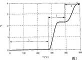
图1是地层中烃类物质的一些加热阶段的示意图。Figure 1 is a schematic diagram of some heating stages of hydrocarbon material in a formation.
图2是用于对地层中烃类物质进行处理的现场转换系统的一部分的实施例的示意图。2 is a schematic diagram of an embodiment of a portion of an in-situ conversion system for processing hydrocarbons in a formation.
图3、4、5是根据一实施例的温度受限加热器的剖面图,该加热器具有外部导体,该外部导体具有铁磁部分和非铁磁部分。3, 4, 5 are cross-sectional views of a temperature limited heater having an outer conductor with a ferromagnetic portion and a non-ferromagnetic portion according to an embodiment.
图6、7、8、9是根据一实施例的温度受限加热器的剖面图,该加热器具有外部导体,该外部导体具有放置在护套内的铁磁部分和非铁磁部分。6, 7, 8, 9 are cross-sectional views of a temperature limited heater having an outer conductor with a ferromagnetic portion and a non-ferromagnetic portion placed within a sheath, according to an embodiment.
图10、11、12是根据一实施例的温度受限加热器的剖面图,该加热器具有铁磁外部导体。10, 11, 12 are cross-sectional views of a temperature limited heater having a ferromagnetic outer conductor according to an embodiment.
图13、14、15是根据一实施例的温度受限加热器的剖面图,该加热器具有外部导体。13, 14, 15 are cross-sectional views of a temperature limited heater having an outer conductor according to one embodiment.
图16A、16B是根据一实施例的温度受限加热器的剖面图,该加热器具有铁磁内部导体。16A, 16B are cross-sectional views of a temperature limited heater having a ferromagnetic inner conductor according to one embodiment.
图17A、17B是根据一实施例的温度受限加热器的剖面图,该加热器具有铁磁内部导体和非铁磁芯。17A, 17B are cross-sectional views of a temperature limited heater having a ferromagnetic inner conductor and a non-ferromagnetic core according to one embodiment.
图18A、18B是根据一实施例的温度受限加热器的剖面图,该加热器具有铁磁外部导体。18A, 18B are cross-sectional views of a temperature limited heater having a ferromagnetic outer conductor according to one embodiment.
图19A、19B是根据一实施例的温度受限加热器的剖面图,该加热器具有铁磁外部导体,该铁磁外部导体被镀有耐腐合金。19A, 19B are cross-sectional views of a temperature limited heater having a ferromagnetic outer conductor plated with a corrosion resistant alloy according to one embodiment.
图20A、20B是根据一实施例的温度受限加热器的剖面图,该加热器具有铁磁外部导体。20A, 20B are cross-sectional views of a temperature limited heater having a ferromagnetic outer conductor according to one embodiment.
图21是根据一实施例的复合导体的剖面图,该复合导体具有支撑元件。21 is a cross-sectional view of a composite conductor having a support element according to an embodiment.
图22是根据一实施例的复合导体的剖面图,该复合导体具有支撑元件,该支撑元件把导体间隔开。22 is a cross-sectional view of a composite conductor having support elements that space the conductors apart according to an embodiment.
图23是根据一实施例的复合导体的剖面图,该复合导体环绕着支撑元件。23 is a cross-sectional view of a composite conductor surrounding a support member according to an embodiment.
图24是根据一实施例的复合导体的剖面图,该复合导体环绕着管道支撑元件。24 is a cross-sectional view of a composite conductor encircling a pipe support element according to an embodiment.
图25是根据一实施例的导体位于管道中的加热器的剖面图。Figure 25 is a cross-sectional view of a heater with conductors located in the conduit according to one embodiment.
图26A、26B是绝缘的导体加热器的一实施例。26A, 26B are an embodiment of an insulated conductor heater.
图27A、27B是绝缘的导体加热器的一实施例,该加热器具有一护套,该护套位于外部导体的外面。Figures 27A, 27B are an embodiment of an insulated conductor heater having a sheath over the outer conductor.
图28是位于管道内部的绝缘的导体的一实施例。Figure 28 is an embodiment of an insulated conductor located inside the pipe.
图29、30、31、32、33、34、35、36表示对于其中杆和管道辐射系数都为0.8的基本情况以及其中杆辐射系数被降低到0.4的低辐射系数情况,加热杆的温度是杆内所产生电流的函数。Figures 29, 30, 31, 32, 33, 34, 35, 36 show that for the base case where the rod and pipe emissivity are both 0.8 and the low emissivity case where the rod emissivity is reduced to 0.4, the temperature of the heated rod is function of the current generated in the rod.
图37表示出了对于在环状空间内具有空气或氦且不同加热器功率而言中央加热杆(辐射系数为0.8)温度与管道温度之间的关系。Figure 37 shows the relationship between central heating rod (0.8 emissivity) temperature and tube temperature for different heater powers with air or helium in the annulus.
图38表示出了对于在环状空间内具有空气或氦且不同加热器功率而言中央加热杆(辐射系数为0.4)温度与管道温度之间的关系。Figure 38 shows the relationship between central heating rod (0.4 emissivity) temperature and tube temperature for different heater powers with air or helium in the annulus.
图39表示出了对于环状空间内具有空气的导体位于管道中的加热器而言,在不同温度,火花间隙击穿电压与压力的关系。Figure 39 shows the spark gap breakdown voltage as a function of pressure at various temperatures for a heater with air in the annulus and a conductor in the tube.
图40表示出了对于环状空间内具有氦的导体位于管道中的加热器而言,在不同温度,火花间隙击穿电压与压力的关系。Figure 40 shows the spark gap breakdown voltage as a function of pressure at various temperatures for a heater with helium conductors in the annulus in the tube.
图41表示对于446不锈钢杆而言,在不同的施加电流,电阻与温度之间的关系。Figure 41 shows the relationship between resistance and temperature at different applied currents for 446 stainless steel rods.
图42表示对于一温度受限加热器在不同的施加电流,电阻与温度之间的关系。Figure 42 shows the relationship between resistance and temperature for a temperature limited heater at different applied currents.
图43表示对于一实心的直径为2.54cm,长度为1.8m的410不锈钢杆在不同的施加电流情况下,电阻与温度之间关系的数据。Figure 43 shows the data of the relationship between resistance and temperature for a solid 410 stainless steel rod with a diameter of 2.54 cm and a length of 1.8 m under different applied current conditions.
图44表示对于一实心的直径为2.54cm,长度为1.8m的410不锈钢杆在不同的施加的交流电电流,集肤深度与温度之间关系的数据。Figure 44 shows the skin depth versus temperature data for a solid 2.54 cm diameter, 1.8 m long 410 stainless steel rod at different applied AC currents.
图45表示一温度受限加热器的温度与时间之间的关系。Fig. 45 shows the relationship between temperature and time for a temperature limited heater.
图46表示出了2.5cm实心410不锈钢杆和2.5cm实心304不锈钢杆的温度与测量时间数据之间的关系。Figure 46 shows the relationship between temperature and measurement time data for a 2.5cm solid 410 stainless steel rod and a 2.5cm solid 304 stainless steel rod.
图47表示出了一种导体位于管道中的加热器的中心导体的温度是调节比为2∶1的一温度受限加热器的地层深度的一个函数。Figure 47 shows the temperature of the center conductor of a heater with conductor in the pipe as a function of formation depth for a temperature limited heater with a turndown ratio of 2:1.
图48表示出了沿着油页岩丰富轮廓对于调节比为2∶1而言通过一地层的加热器热流量。Figure 48 shows heater heat flow through a formation for a turndown ratio of 2:1 along an oil shale rich profile.
图49表示出了对于调节比为3∶1而言,加热器温度与地层深度之间的函数关系。Figure 49 shows heater temperature as a function of formation depth for a turndown ratio of 3:1.
图50表示出了沿着油页岩丰富轮廓对于调节比为3∶1而言通过一地层的加热器热流量。Figure 50 shows heater heat flow through a formation for a turndown ratio of 3:1 along an oil shale rich profile.
图51表示出了对于调节比为4∶1而言,加热器温度与地层深度之间的函数关系。Figure 51 shows heater temperature as a function of formation depth for a turndown ratio of 4:1.
图52表示出了对于在模拟中用于对油页岩进行加热的加热器而言,加热器温度与深度之间的函数关系。Figure 52 shows heater temperature as a function of depth for the heaters used to heat oil shale in the simulation.
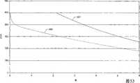
图53表示出了对于在模拟中用于对油页岩进行加热的加热器而言,加热器热流量与时间的函数关系。Figure 53 shows the heater heat flow as a function of time for the heater used to heat the oil shale in the simulation.
图54表示出了在对油页岩进行加热的模拟中,累积的热输出与时间之间的函数关系。Figure 54 shows the cumulative heat output as a function of time in a simulation of heating oil shale.
尽管本发明可以具有各种变型,可采用其它的一些形式,但图中通过举例的方式给出了本发明的一些具体实施例,这些具体实施例在这里将被详细描述,附图并不是按比例绘制的。然而,应当知道,附图和所作的详细描述并不是要把本发明局限于所公开的具体形式,相反,本发明应包括落入本发明构思和范围之内的所有的变型、等同方案和替代方案,本发明的范围是由所附的权利要求来限定的。Although the present invention may have various modifications and other forms, some specific embodiments of the present invention are shown by way of example in the drawings, and these specific embodiments will be described in detail here, and the drawings are not in accordance with drawn to scale. It should be understood, however, that the drawings and detailed description are not intended to limit the invention to the particular forms disclosed, but on the contrary, the invention is to include all modifications, equivalents, and alternatives falling within the spirit and scope of the invention Rather, the scope of the invention is defined by the appended claims.
具体实施方式Detailed ways
利用这里所描述的系统、方法和加热器就可以解决上述问题。例如,系统包括电导体,该电导体被构造成在把电流施加到电导体期间产生电阻热输出。电导体可包括电阻铁磁材料。一管道可至少部分地环绕着电导体。流体可以被定位在电导体和管道之间的空间中。在空间中的温度和101kPa状态下,流体与空气相比具有较高的热导率。系统被构造成在选定温度附近或该选定温度以上时能提供减小的热量。The above problems are addressed using the systems, methods and heaters described herein. For example, a system includes an electrical conductor configured to generate a resistive heat output during application of electrical current to the electrical conductor. The electrical conductor may comprise a resistive ferromagnetic material. A conduit may at least partially surround the electrical conductor. Fluid can be positioned in the space between the electrical conductor and the pipe. At the temperature in space and the state of 101kPa, the fluid has a higher thermal conductivity than air. The system is configured to provide reduced heat around or above a selected temperature.
在这里更详细描述的本发明的一些实施例涉及用于对地层中的烃类物质进行加热的系统和方法。这些地层可以被处理,以便生产出烃类产品、氢气或其它产品。在这里所使用的术语被定义如下:Some embodiments of the invention described in greater detail herein relate to systems and methods for heating hydrocarbon material in a formation. These formations can be treated to produce hydrocarbon products, hydrogen or other products. Terms used herein are defined as follows:
“烃类物质”总体上被定义为主要由碳和氢原子构成的分子。烃类物质也可包括其它一些元素,例如卤族元素、金属元素、氮、氧和/或硫,但并不局限于这些元素。烃类物质可以是油母岩、沥青、焦沥青、油、天然矿物蜡、沥青岩,但不局限于这些。烃类物质可以位于地层的矿石中或其附近,矿石可包括沉积岩、砂岩、硅酸岩、碳酸岩、硅藻土和其它多孔介质,但并不局限于这些。“烃类流体”是指包含烃类物质的流体。烃类流体可包括、夹杂或可被夹杂在非烃类流体(例如氢、氮、一氧化碳、二氧化碳、硫化氢、水、氨)中。"Hydrocarbons" are generally defined as molecules composed primarily of carbon and hydrogen atoms. The hydrocarbon material may also include some other elements, such as halogen elements, metal elements, nitrogen, oxygen and/or sulfur, but is not limited to these elements. The hydrocarbon material can be kerogen, bitumen, pyrobitumen, oil, natural mineral wax, bituminous rock, but is not limited to these. Hydrocarbons may be located in or near ores in the formation, which may include, but are not limited to, sedimentary rocks, sandstones, silicate rocks, carbonatites, diatomaceous earth, and other porous media. "Hydrocarbon fluid" means a fluid comprising hydrocarbon species. Hydrocarbon fluids may include, entrain, or may be entrained in non-hydrocarbon fluids (eg, hydrogen, nitrogen, carbon monoxide, carbon dioxide, hydrogen sulfide, water, ammonia).
“地层”包括一个或多个含烃类物质的层、一个或多个非烃类物质层、覆盖层和/或下底层。覆盖层和/或下底层可包括岩石、页岩、泥岩或湿的/紧密的碳酸岩。在现场转换方法的一些实施例中,覆盖层和/或下底层可包括含烃类物质的层或者一些含烃类物质的层,在现场转换处理期间,这些含烃类物质的层是相对不渗透的并且不受温度影响,所述的现场转换处理导致覆盖层和/或下底层的这些含烃类物质的层的特性发生相当大的改变。例如,覆盖层可包含页岩或泥岩,但在现场转换处理期间,下底层不允许被加热至热解温度。在某些情况下,覆盖层和/或下底层可以有点渗透性。A "formation" includes one or more hydrocarbon-bearing layers, one or more non-hydrocarbon layers, overburdens, and/or subburdens. Overburden and/or the underlying substratum may include rock, shale, mudstone or wet/compact carbonatite. In some embodiments of the in situ conversion process, the overburden and/or the underlying substratum may include a hydrocarbonaceous layer or layers that are relatively inert during the in situ conversion process. Permeable and independent of temperature, the in situ conversion treatment results in considerable changes in the properties of these hydrocarbonaceous layers of the overburden and/or underlying substratum. For example, the overburden may contain shale or mudstone, but the underlying substratum is not allowed to be heated to pyrolysis temperatures during in-situ conversion processing. In some cases, the overlay and/or the underlying subfloor may be somewhat permeable.
“地层流体”和“产出流体”指的是从地层中开采出的流体,可包括热解流体,合成气体,动化的烃类物质和水(蒸汽)。地层流体可包括烃类流体和非烃类流体。"Formation fluids" and "produced fluids" refer to fluids produced from a formation and may include pyrolysis fluids, synthesis gas, mobilized hydrocarbons, and water (steam). Formation fluids may include hydrocarbon fluids and non-hydrocarbon fluids.
“热导流体”包括这样的流体,在标准温度和压力(STP)(0℃和101.325kPa)下,该流体与空气相比具有更高的热导率。"Heat transfer fluid" includes a fluid that has a higher thermal conductivity than air at standard temperature and pressure (STP) (0°C and 101.325 kPa).
“加热器”是用于在井筒或在井筒区域附近产生热量的任何系统。加热器可以是电加热器、循环换热流体或蒸汽、炉、与地层中的材料或与从地层中生产出的材料进行反应的燃烧室、和/或它们的组合,但并局限于这些。A "heater" is any system for generating heat in or near a wellbore region. The heaters may be, but are not limited to, electric heaters, circulating heat exchange fluid or steam, furnaces, combustors that react with material in or produced from the formation, and/or combinations thereof.
“温度受限加热器”总体上是指这样的加热器,它无需利用外部控制例如温度控制器、功率调节器、调整器或其它装置,就能在一规定温度范围以上调节热量输出(例如,减小热量输出)。温度受限加热器可以是交流电(AC)供电的或调制(例如“突变”)直流电(DC)供电的电阻加热器。"Temperature limited heater" refers generally to a heater that regulates heat output over a specified temperature range without the use of external controls such as temperature controllers, power regulators, regulators, or other devices (e.g., reduce heat output). The temperature limited heater may be an alternating current (AC) powered or modulated (eg "burst") direct current (DC) powered resistive heater.
“居里温度”是指这样的温度,即,在该温度以上,铁磁材料就失去其全部的铁磁特性。铁磁材料除了在居里温度以上失去其全部的铁磁特性以外,在增大的电流通过该铁磁材料时也开始失去其铁磁特性。"Curie temperature" means the temperature above which a ferromagnetic material loses all of its ferromagnetic properties. In addition to losing all of its ferromagnetic properties above the Curie temperature, ferromagnetic materials also begin to lose their ferromagnetic properties when increasing current is passed through the ferromagnetic material.
“随时间变化的电流”是指这样的电流,即,该电流的大小随着时间而变化。随时间变化的电流包括交流电(AC)和调制直流电(DC)。"Time-varying current" refers to a current whose magnitude changes with time. Time-varying currents include alternating current (AC) and modulated direct current (DC).
“交流电(AC)”是指随时间变化的电流,该电流基本上以正弦方式进行反向。交流电在铁磁导体中产生集肤效应电流流动。"Alternating current (AC)" means a time-varying electrical current that reverses direction substantially sinusoidally. Alternating current creates a skin effect current flow in a ferromagnetic conductor.
“调制直流电(DC)”是指任何基本上非正弦的随时间变化的电流,该电流在铁磁导体中产生集肤效应电流流动。"Modulated direct current (DC)" means any substantially non-sinusoidal time-varying current that produces skin-effect current flow in a ferromagnetic conductor.
温度受限加热器的“调节比”是指对于给定电流而言,在居里温度以下最高交流电或调制直流电电阻与在居里温度以上最低电阻的比值。The "turndown ratio" of a temperature limited heater is the ratio of the highest AC or modulated DC resistance below the Curie temperature to the lowest resistance above the Curie temperature for a given current.
术语“井筒”是指通过钻进或把管道插入到地层内所形成的地层中的孔眼。在本文中,术语“井眼”和“井孔”,当指地层中的孔眼时,它们与术语“井筒”是可互换使用的。The term "wellbore" refers to a borehole in a formation formed by drilling or inserting a pipe into the formation. Herein, the terms "wellbore" and "wellbore" are used interchangeably with the term "wellbore" when referring to a perforation in a subterranean formation.
“绝缘导体”是指这样的细长材料,即,它能导电,并且全部或部分地被绝缘材料包裹着。术语“自控制”是指采取无需任何形式的外部控制的方式来控制加热器的输出。"Insulated conductor" means an elongated material which is capable of conducting electricity and which is wholly or partially surrounded by an insulating material. The term "self-controlling" means controlling the output of the heater in a manner that does not require any form of external control.
在减小热量输出的加热系统、装置和方法中的上下文中,术语“自动”的意思是这些系统、装置和方法以特定方式起作用,无需采用外部控制(例如外部控制器,如具有温度传感器和反馈回路的控制器,PID控制器或预测控制器)。In the context of heating systems, devices and methods that reduce heat output, the term "automatic" means that these systems, devices and methods function in a specific manner without the use of external controls (e.g. and feedback loop controllers, PID controllers or predictive controllers).
地层中的烃类物质可以以各种方式被处理,以便生产出许多不同的产品。在某些实施例中,这些地层被分阶段处理。图1表示出了对含有烃类物质的一部分地层进行加热的若干阶段。图1还表示出了(y轴)地层的每吨的以桶计的油当量的产量(Y)与(x轴)加热地层以摄氏度计的温度(T)之间的关系。Hydrocarbons in the formation may be processed in various ways to produce many different products. In certain embodiments, these formations are treated in stages. Figure 1 shows the stages of heating a portion of a formation containing hydrocarbons. Figure 1 also shows the relationship between (y-axis) production per ton of barrels of oil equivalent (Y) of the formation and (x-axis) temperature (T) at which the formation is heated in degrees Celsius.
在阶段1加热期间,发生甲烷解吸附和水的蒸发。通过阶段1对地层进行加热可以被尽快地进行。当地层被开始加热时,地层中的烃类物质就把吸附的甲烷释放出来。被解吸附的甲烷可以从地层中被开采出来。如果地层被进一步加热,那么,地层中的水就被蒸发。在地层中,水通常在160℃和285℃之间和在600kPa绝对压力至7000kPa绝对压力之间被蒸发。在某些实施例中,蒸发的水在地层中产生可湿性改变和/或使地层压力增大。可湿性改变和/或压力增大会影响地层中的热解反应或其它反应。在某些实施例中,蒸发的水从地层被开采出来。在其它一些实施例中,蒸发的水在地层中或地层外被用于蒸汽提取和/或蒸馏。通过把水从地层中去除,并增大地层中的孔容积,就可以增大孔容积中存储烃类物质的存储空间。During
在某些实施例中,在阶段1加热之后,部分地层被进一步加热,从而使得部分地层中的温度(至少)达到开始热解温度(例如,如阶段2所示的温度范围的下端点的温度)。在整个阶段2,地层中的烃类物质可以被热解。热解温度范围随着地层中的烃的种类的不同而改变。热解温度范围可包括位于250℃至900℃之间的温度。用于开采期望产品的热解温度范围只可通过整个热解温度范围的一部分延伸。在某些实施例中,用于开采期望产品的热解温度范围可包括250℃至400℃之间的温度、250℃至350℃之间的温度、或325℃至400℃之间的温度。如果地层中的烃类物质的温度通过从250℃至400℃的温度范围缓慢升高,那么,当温度到达400℃时,热解产品的开采就可以基本完成。利用许多加热器对地层进行加热,可以使那些通过热解温度范围使地层中的烃类物质的温度缓慢升高的热量进行叠加。In certain embodiments, after
在某些现场转变实施例中,一部分地层被加热至期望温度,而不是通过热解温度范围来缓慢地加热。在某些实施例中,期望温度为300℃。在某些实施例中,期望温度为325℃。在某些实施例中,期望温度为350℃。其它的温度也可以被选择作为期望温度。来自多个加热器的热量的叠加,使得在地层中可以相对快速和有效地达到期望温度。从加热器向地层中输出的能量可以被调节,以便使地层中的温度保持在期望温度。地层的被加热部分基本上被保持在期望温度,直到热解衰减而使从地层中开采期望地层流体变得不经济为止。产生热解的部分地层可包括这样一些区域,这些区域只通过一个加热器的热传递来使其温度处于热解温度范围内。In certain in situ conversion embodiments, a portion of the formation is heated to a desired temperature rather than being heated slowly through the pyrolysis temperature range. In certain embodiments, the desired temperature is 300°C. In certain embodiments, the desired temperature is 325°C. In certain embodiments, the desired temperature is 350°C. Other temperatures may also be selected as the desired temperature. The superimposition of heat from multiple heaters allows the desired temperature to be achieved in the formation relatively quickly and efficiently. The energy output from the heater into the formation may be adjusted to maintain the temperature in the formation at a desired temperature. The heated portion of the formation is maintained substantially at the desired temperature until pyrolysis decays such that it becomes uneconomical to produce the desired formation fluids from the formation. The portion of the formation that undergoes pyrolysis may include regions that are brought to a temperature within the pyrolysis temperature range by only heat transfer from a heater.
在某些实施例中,包括热解流体的地层流体从地层中被开采出来。随着地层温度的升高,开采地层流体中可凝缩的烃类物质的量会降低。在非常高的温度下,地层主要产生甲烷和/或氢。如果地层在整个热解范围内被加热,那么,朝着热解范围的上限,地层就可只产生少量的氢。在大部分可获得的氢采完之后,就将从地层中开采少量的流体。In certain embodiments, formation fluids, including pyrolysis fluids, are produced from the formation. As the temperature of the formation increases, the amount of condensable hydrocarbon species in the produced formation fluid decreases. At very high temperatures, the formation produces primarily methane and/or hydrogen. If the formation is heated throughout the pyrolysis range, then, towards the upper end of the pyrolysis range, the formation may produce only small amounts of hydrogen. After most of the available hydrogen has been produced, a small amount of fluid will be produced from the formation.
在烃类物质热解之后,在加热部分的地层中仍然存在大量的碳和一些氢。保留在加热部分的地层中的一部分碳可以以合成气体的形式从地层中被开采出来。合成气体的产生可发生在图1所示的阶段3加热期间。阶段3可包括把经加热部分的地层加热到一个足以允许产生合成气体的温度。可以在400℃至1200℃,500℃至1100℃,或550℃至1000℃的温度范围中开采合成气体。当合成气体产生流体被引入到地层时,加热部分的地层的温度决定了从该地层中所开采出的合成气体的组分。可以通过一个或多个开采井眼来开采所产生的合成气体。After pyrolysis of the hydrocarbons, a significant amount of carbon and some hydrogen are still present in the heated portion of the formation. A portion of the carbon remaining in the formation in the heated portion can be extracted from the formation in the form of synthesis gas. Synthesis gas production can occur during
图2表示出了用于对含有烃类物质的地层进行处理的现场转变系统中的一部分的实施例的示意图。加热器100被放置在至少一部分地层中。加热器100向至少一部分地层提供热量,以便对地层中的烃类物质进行加热。能量可以通过供给管线102被供给到加热器100。供给管线102的结构可以根据加热地层所用的加热器类型的不同而不同。加热器的供给管线102可以为电加热器传送电,可以为燃烧器传送燃料,或者可以传送在地层中循环流动的热交换流体。Figure 2 shows a schematic diagram of an embodiment of a portion of an in situ conversion system for treating a formation containing hydrocarbons.
生产井104被用于从地层中开采地层流体。从生产井104中开采出的地层流体可以通过收集管道106被传送至处理设备108。地层流体也可从加热器100被开采出来。例如,流体可以从加热器100被开采出来,以便控制邻近加热器的地层中的压力。从加热器100开采的流体可以通过管系或管道被输送至收集管道106,或者是,开采出的流体可以通过管系或管道直接被输送至处理设备108。处理设备108可包括分离单元、反应单元、浓缩单元、从气体中去除硫的单元、燃料室、透平机、存储容器、和/或用于对开采出的地层流体进行加工处理的其它系统和单元。Production wells 104 are used to produce formation fluids from the formation. Formation fluid produced from production well 104 may be conveyed to processing facility 108 through collection conduit 106 . Formation fluids may also be produced from
用于对烃类物质进行处理的现场转变系统可包括一些隔离井110。这些隔离井110被用于在一处理区域周围形成隔离。该隔离阻止流体流入和/或流出处理区域。隔离井包括脱水井、真空井、捕获井、注射井、灌浆井、冻井、或它们的组合,但并不局限于这些。在某些实施例中,隔离井110是一些脱水井。脱水井可以去除液态水和/或阻止液态水进入要被加热的一部分地层或正在被加热的地层。在图2所示实施例中,表示出了脱水井只沿着加热器100的一侧延伸,但是,脱水井通常环绕在被用于或将被用于对地层进行加热的全部加热器100周围。An on-site diversion system for processing hydrocarbons may include isolated wells 110 . These isolation wells 110 are used to create isolation around a processing area. The isolation prevents fluid from flowing into and/or out of the treatment area. Isolation wells include, but are not limited to, dehydration wells, vacuum wells, trap wells, injection wells, grout wells, freeze wells, or combinations thereof. In some embodiments, isolation wells 110 are dewatering wells. Dewatering wells may remove liquid water and/or prevent liquid water from entering a portion of the formation that is to be heated or that is being heated. In the embodiment shown in FIG. 2, the dewatering wells are shown extending along only one side of the
如图2所示,除了加热器100以外,在地层中还可以设置一个或多个生产井104。可以通过生产井104来开采地层流体。在某些实施例中,生产井104包括加热器。生产井中的加热器可以对生产井处及其附近的地层的一个或多个部分进行加热,并且允许地层流体的气相去除。对从生产井进行液体的高温泵送的需要被减少或消除。避免或限制高温液体泵送可以显著减小生产成本。在生产井或通过生产井提供热量,可以:(1)当开采流体正在覆盖层附近的生产井中移动时,阻止这种开采流体的冷凝和/或回流,(2)增大向地层内的热量输入,和/或(3)在生产井处或其附近增大地层的可渗透性。在某些现场转变处理实施例中,从生产井的每米生产井供给到地层的热量要小于从对地层进行加热的加热器的每米加热器供给到地层的热量。As shown in FIG. 2, in addition to the
某些实施例的加热器包括开关(例如,熔丝和/或恒温件),当加热器中到达特定条件时,开关就关闭加热器的电源或部分加热器。在某些实施例中,利用温度受限加热器来向地层中的烃类物质提供热量。Some embodiments of the heater include a switch (eg, a fuse and/or a thermostat) that turns off power to the heater or a portion of the heater when certain conditions are reached in the heater. In certain embodiments, temperature limited heaters are utilized to provide heat to hydrocarbon material in the formation.
温度受限加热器可以有多种结构,和/或包括这样一些材料,这些材料在特定温度为加热器提供自动的温度限制特性。在某些实施例中,铁磁材料被用在温度受限加热器中。铁磁材料在该材料的居里温度或其附近可以自限制温度,以便当向该材料施加随时间变化的电流时,在居里温度或其附近能提供减小的热量。在某些实施例中,在选定温度条件下,铁磁材料对温度受限加热器的温度进行自限制,所述的选定温度大约为居里温度。在某些实施例中,所选定的温度在居里温度的约35℃范围内、约25℃范围内、约20℃范围内、或约10℃范围内。在某些实施例中,铁磁材料与其他材料(例如高导材料、高强度材料、耐腐材料或它们的组合)相接合,以便提供各种电特性和/或机械特性。温度受限加热器的某些部分所具有的电阻比温度受限加热器的其它部分要低(这是由不同的几何形状和/或利用不同的铁磁和/或非铁磁材料造成的)。通过使温度受限加热器的各个部分具有不同的材料和/或尺寸大小,就可以使加热器的每个部分适应所期望的热量输出。Temperature limited heaters can be of various constructions, and/or include materials that provide the heater with automatic temperature limiting characteristics at specific temperatures. In some embodiments, ferromagnetic materials are used in temperature limited heaters. Ferromagnetic materials are self-limiting in temperature at or near the Curie temperature of the material so as to provide reduced heat at or near the Curie temperature when a time-varying electrical current is applied to the material. In some embodiments, the ferromagnetic material self-limits the temperature of the temperature-limited heater at a selected temperature, said selected temperature being approximately the Curie temperature. In certain embodiments, the selected temperature is within about 35°C, within about 25°C, within about 20°C, or within about 10°C of the Curie temperature. In some embodiments, ferromagnetic materials are combined with other materials (eg, highly conductive materials, high strength materials, corrosion resistant materials, or combinations thereof) to provide various electrical and/or mechanical properties. Some parts of the temperature limited heater have a lower resistance than other parts of the temperature limited heater (due to different geometries and/or use of different ferromagnetic and/or non-ferromagnetic materials) . By having different materials and/or dimensions for each part of the temperature limited heater, it is possible to tailor each part of the heater to the desired heat output.
温度受限加热器可以比其它加热器更可靠些。温度受限加热器较不易因地层中的热点而破损或发生故障。在某些实施例中,温度受限加热器可以基本均匀地对地层进行加热。在某些实施例中,温度受限加热器通过沿加热器的整个长度以更高的平均热量输出运作,从而能够更有效地对地层进行加热。温度受限加热器沿着加热器的整个长度以较高的平均热量输出进行运作,这是因为如果沿着加热器任何点的温度超过或将超过加热器的最大工作温度,那么针对整个加热器而言,供向加热器的功率无需减小,而对于典型的恒定瓦特数的加热器却是必须减小供向加热器的功率。从达到加热器的居里温度的温度受限加热器的各部分的热量输出会自动减小,而无需对施加到加热器的电流进行受控调节。由于温度受限加热器各部分的电学特性(例如电阻)发生改变,因此,热量输出会自动减小。这样,在较大部分热处理期间,温度受限加热器能提供更大的功率。Temperature limited heaters can be more reliable than other heaters. Temperature limited heaters are less prone to breakage or failure from hot spots in the formation. In certain embodiments, the temperature limited heater may heat the formation substantially uniformly. In certain embodiments, the temperature limited heater can more efficiently heat the formation by operating at a higher average heat output along the entire length of the heater. Temperature limited heaters operate at a higher average heat output along the entire length of the heater because if the temperature at any point along the heater exceeds or will exceed the maximum operating temperature of the heater, then the temperature for the entire heater In this case, the power to the heater does not need to be reduced, which is necessary for typical constant wattage heaters. Heat output from portions of a temperature-limited heater that reaches the Curie temperature of the heater is automatically reduced without the need for controlled adjustments to the current applied to the heater. As the electrical properties (such as resistance) of the various parts of the temperature limited heater change, the heat output is automatically reduced. In this way, the temperature limited heater can provide more power during a greater portion of the heat treatment.
在某些实施例中,具有温度受限加热器的系统当通过随时间变化的电流对温度受限加热器激励时,在加热器的电阻部分的居里温度或该温度附近或之上,起初提供第一热输出,然后提供减小的(第二热输出)热输出。第一热输出是温度受限加热器开始自限制的温度以下的热输出。在一些实施例中,第一热输出是在温度受限加热器中的铁磁材料的居里温度以下的50℃、75℃、100℃、或125℃的温度状态下的热输出。In certain embodiments, a system having a temperature-limited heater, when the temperature-limited heater is energized by a time-varying current, at or near or above the Curie temperature of the resistive portion of the heater, initially A first heat output is provided and then a reduced (second heat output) heat output is provided. The first heat output is the heat output of the temperature limited heater starting from below the limited temperature. In some embodiments, the first heat output is the heat output at a temperature regime of 50°C, 75°C, 100°C, or 125°C below the Curie temperature of the ferromagnetic material in the temperature limited heater.
温度受限加热器可由在井头(wellhead)提供的随时间变化的电流(交流电或调制直流电)来激励。井头可包括电源和其它用于向温度受限加热器供电的部件(例如调制部件、转换器和/或电容)。该温度受限加热器可以是用于对一部分地层进行加热的许多加热器中的一个。The temperature limited heater can be energized by a time-varying electrical current (alternating current or modulated direct current) provided at the wellhead. The wellhead may include a power supply and other components (eg, modulation components, converters, and/or capacitors) for powering the temperature-limited heater. The temperature limited heater may be one of many heaters used to heat a portion of the formation.
在某些实施例中,温度受限加热器包括导体,当向该导体施加随时间变化的电流时,该导体就作为一种集肤效应或邻近效应加热器进行工作。集肤效应限制电流渗透到该导体内的深度。对于铁磁材料而言,集肤效应由导体的导磁率决定。铁磁材料的相对导磁率通常在10至1000之间(例如,铁磁材料的相对导磁率通常至少为10,至少为50,100,500,1000或更大)。随着铁磁材料的温度升高到居里温度之上和/或随着所施加的电流的增大,铁磁材料的导磁率显著减小,从而集肤深度迅速增大(例如,集肤深度以导磁率的反平方根进行增大)。导磁率的减小,导致在居里温度或该温度附近或之上和/或随着所施加电流的增大,所述导体的交流电或调制直流电电阻减小。当温度受限加热器由基本上恒定电流的电源供电时,加热器的那些接近、达到或高于居里温度的部分可以减小散热。温度受限加热器的那些不位于居里温度或其附近的部分由集肤效应加热支配,从而允许加热器具有高散热,这是由于较高电阻负荷的缘故。In certain embodiments, the temperature limited heater includes a conductor that operates as a skin effect or proximity effect heater when a time-varying electrical current is applied to the conductor. The skin effect limits the depth to which current can penetrate into the conductor. For ferromagnetic materials, the skin effect is determined by the magnetic permeability of the conductor. Ferromagnetic materials typically have a relative permeability between 10 and 1000 (eg, ferromagnetic materials typically have a relative permeability of at least 10, at least 50, 100, 500, 1000 or more). As the temperature of the ferromagnetic material increases above the Curie temperature and/or as the applied current increases, the magnetic permeability of the ferromagnetic material decreases significantly and thus the skin depth increases rapidly (e.g., skin Depth increases with the inverse square root of permeability). The decrease in magnetic permeability results in a decrease in the AC or modulated DC resistance of the conductor at or near or above the Curie temperature and/or as the applied current increases. When the temperature limited heater is powered by a substantially constant current source, those portions of the heater that are near, at, or above the Curie temperature can reduce heat dissipation. Those portions of the temperature-limited heater that are not at or near the Curie temperature are dominated by skin effect heating, allowing the heater to have high heat dissipation due to the higher resistive load.
居里温度加热器已被应用在焊接设备、医疗应用加热器和烤炉加热元件中。这些应用中一部分应用在Lamome等人的美国专利US5579575,Henschen等人的US5065501,Yagnik等人的US5512732中被公开了。在Whitney等人的US4849611中描述了许多离散的间隔开的一些加热单元,这些加热单元包括反应部件、电阻加热部件和温度响应部件。Curie temperature heaters have been found in welding equipment, medical application heaters and oven heating elements. Some of these applications are disclosed in US Pat. No. 5,579,575 to Lamome et al., US Pat. In US4849611 to Whitney et al. a number of discrete spaced-apart heating units are described which include reactive elements, resistive heating elements and temperature responsive elements.
利用温度受限加热器对地层中的烃类物质进行加热的一个优点在于:导体被选择成具有在期望的工作温度范围内的居里温度。在期望工作温度范围内的操作允许大量的热被注入至地层内,同时把温度受限加热器和其它设备的温度保持在设计极限温度之下。设计极限温度是这样的一些温度,即,在这些温度,一些特性例如腐蚀性能、蠕变性能和/或变形性能会受到不利的影响。温度受限加热器的这些温度限制特性可阻止位于地层中的低热导率“热点”附近的加热器过热或烧毁。在某些实施例中,温度受限加热器能降低或控制热量输出和/或承受在25℃,37℃,100℃,250℃,500℃,700℃,800℃,900℃之上或高达1131℃的温度,这取决于加热器中所用的材料。One advantage of utilizing temperature limited heaters to heat hydrocarbons in the formation is that the conductors are selected to have a Curie temperature within the desired operating temperature range. Operation within the desired operating temperature range allows a substantial amount of heat to be injected into the formation while maintaining the temperature of temperature limited heaters and other equipment below design limit temperatures. Design limit temperatures are those temperatures at which properties such as corrosion properties, creep properties and/or deformation properties are adversely affected. These temperature limiting properties of temperature limited heaters prevent heaters located near low thermal conductivity "hot spots" in the formation from overheating or burning out. In certain embodiments, temperature limited heaters are capable of reducing or controlling heat output and/or withstand temperatures above or up to 25°C, 37°C, 100°C, 250°C, 500°C, 700°C, 800°C, 900°C 1131°C temperature, depending on the materials used in the heater.
温度受限加热器允许向地层内输入的热量要比恒定瓦特数的加热器所输入的热量多,这是由于输入到温度受限加热器内的能量无需被限制以适应加热器附近的低热导区域的缘故。例如,在格林河(GreenRiver)油页岩中,在最低富的油页岩层和最高富的油页岩层的热导率具有至少系数为3的差别。当加热这种地层时,与利用传统加热器相比,利用温度受限加热器时有较多的热量被传递到地层,而传统加热器被温度限制在低热导层。沿着传统加热器整个长度的热量输出需要适应低热导层,以便使加热器在低热导层不会过热和烧毁。对于温度受限加热器而言,位于处于高温的低热导层附近的热量输出将减小,但温度受限加热器的不处于高温状态的剩余部分仍然会提供高的热量输出。由于用于对含烃类物质的地层进行加热的加热器的长度通常较长(例如,至少10米,100米,300米,至少500米,1千米或长达10千米),因而,温度受限加热器的大部分长度可在居里温度以下工作,而只有一小部分在受限加热器的居里温度或该温度附近。Temperature-limited heaters allow more heat input into the formation than constant wattage heaters since the energy input into temperature-limited heaters need not be limited to accommodate the low thermal conductivity near the heater region's sake. For example, in the Green River oil shale, there is a difference in thermal conductivity between the lowest and highest richest oil shale formations by a factor of at least 3. When heating such formations, more heat is transferred to the formation using temperature-limited heaters than with conventional heaters, which are temperature-limited to low thermal conductivity layers. The heat output along the entire length of a traditional heater needs to accommodate the low thermal conductivity layer so that the heater does not overheat and burn out in the low thermal conductivity layer. For a temperature limited heater, the heat output will be reduced near the low thermal conductivity layer that is at high temperature, but the remaining portion of the temperature limited heater that is not at high temperature will still provide high heat output. Since heaters used to heat formations containing hydrocarbons are typically relatively long (e.g., at least 10 meters, 100 meters, 300 meters, at least 500 meters, 1 kilometer, or as long as 10 kilometers), therefore, Most of the length of a temperature-limited heater is operable below the Curie temperature, while only a small portion is at or near the Curie temperature of the limited heater.
温度受限加热器的使用使得能够高效地向地层传递热量。通过高效的热量传递,就可以减小把地层加热至期望温度所需要的时间。例如,当传统恒定瓦特数的加热器采用12米加热井间距时,在格林河油页岩中,热解通常需要9.5年至10年的加热。对于相同的加热器间距,温度受限加热器可具有较大的平均热量输出,同时把加热器设备温度保持在低于设备设计极限温度以下。由于温度受限加热器所提供的平均热量输出要比恒定瓦特数的加热器所提供的平均热量输出大,因此,采用温度受限加热器,就可使地层中的热解在更早的时间发生。例如,在格林河油页岩中,利用温度受限加热器,加热井间距12米,就可以在5年中产生热解。由于井间距不精确,或者钻井时使加热井相互靠得太近,温度受限加热器可抵消热点。在某些实施例中,对于间隔太远的加热井而言,温度受限加热器允许长时间地增大功率输出,或者是,对于相距太近的加热井而言,允许限制功率输出。温度受限加热器还在覆盖层和下底层附近的区域提供更大的功率,以便补偿这些区域中的温度损失。The use of temperature limited heaters enables efficient heat transfer to the formation. Through efficient heat transfer, the time required to heat the formation to the desired temperature can be reduced. For example, pyrolysis typically requires 9.5 to 10 years of heating in the Green River oil shale when traditional constant wattage heaters are used with 12-m heater well spacing. For the same heater spacing, a temperature limited heater can have a greater average heat output while maintaining the heater device temperature below the device design limit temperature. Since the average heat output provided by a temperature-limited heater is greater than that provided by a constant wattage heater, the use of a temperature-limited heater allows for earlier pyrolysis in the formation occur. For example, in the Green River oil shale, pyrolysis can be produced in 5 years using temperature-limited heaters with heater wells spaced 12 meters apart. Temperature-limited heaters can counteract hot spots due to imprecise well spacing, or when drilling wells with heater wells too close to each other. In some embodiments, temperature limited heaters allow for increased power output for extended periods of time for wells that are too far apart, or limit power output for wells that are too close together. The temperature-limited heater also provides more power to areas near the overburden and subfloor in order to compensate for temperature losses in these areas.
有利地是,温度受限加热器可以被用于许多类型的地层中。例如,在沥青沙地层或渗透性相当大的含有重烃类物质的地层中,温度受限加热器可以被用于提供可控制的低温输出,以便减小流体的粘度,促使流体流动和/或在井筒或其附近或在地层中提高流体的径向流量。温度受限加热器可以被用于阻止地层的井筒区域附近因过热而形成过多的焦炭。Advantageously, temperature limited heaters may be used in many types of formations. For example, in tar sands formations or formations containing heavy hydrocarbons with considerable permeability, temperature-limited heaters may be used to provide a controlled low temperature output in order to reduce fluid viscosity, facilitate fluid flow and/or Increase the radial flow of fluids in or near the wellbore or in the formation. Temperature limited heaters may be used to prevent excessive coke formation due to overheating near the wellbore region of the formation.
在某些实施例中,通过使用温度受限加热器,就可以消除或减小对昂贵的温度控制回路的需要。例如,通过使用温度受限加热器,就可以消除或减小对执行温度测量的需要和/或在加热器上利用固定热偶以便监测在热点处的潜在过热的需要。In some embodiments, by using temperature limited heaters, the need for expensive temperature control loops can be eliminated or reduced. For example, by using a temperature limited heater, the need to perform temperature measurements and/or utilize fixed thermocouples on the heater to monitor potential overheating at hot spots can be eliminated or reduced.
在某些实施例中,温度受限加热器比标准的加热器制造起来更经济。典型的铁磁材料包括:铁、碳钢或铁素体不锈钢。与绝缘导体(矿物绝缘缆)加热器中常用的镍基加热合金(例如,镍铬合金,商标为KanthalTM(Bulten-Kanthal AB,瑞典)和/或商标为LOHMTM(Driver-Harris公司,Harrison,NJ))相比,这些材料是便宜的。在温度受限加热器的一个实施例中,温度受限加热器以连续长度的方式被制造成绝缘导体加热器,以便降低成本和提高可靠性。In some embodiments, temperature limited heaters are more economical to manufacture than standard heaters. Typical ferromagnetic materials include: iron, carbon steel or ferritic stainless steel. Nickel-based heating alloys commonly used in insulated conductor (Mineral Insulated Cable) heaters (e.g. Nichrome under the trademark KanthalTM (Bulten-Kanthal AB, Sweden) and/or under the trademark LOHMTM (Driver-Harris Company, Harrison , NJ)) these materials are cheap. In one embodiment of the temperature limited heater, the temperature limited heater is fabricated as an insulated conductor heater in a continuous length to reduce cost and increase reliability.
在某些实施例中,诸如氦的导热流体可以被放置到温度受限加热器内,以便改善加热器内的热传导。导热流体包括导热的、电绝缘的、放热透明的气体,但并不局限于这些气体。在某些实施例中,在标准温度和压力(STP)(0℃和101.325kPa)下,空隙容积内的导热流体所具有的导热率高于空气的导热率。放热透明气体包括这样的气体,即这些气体具有双原子或单原子并且不会吸收大量的红外线能量。在某些实施例中,导热流体包括氦和/或氢。导热流体也可以是热稳定的。例如,导热流体不会热裂,也不会形成不需要的残留。In some embodiments, a heat transfer fluid, such as helium, may be placed into the temperature limited heater to improve heat transfer within the heater. Thermally conductive fluids include, but are not limited to, thermally conductive, electrically insulating, exothermic transparent gases. In certain embodiments, the heat transfer fluid within the void volume has a higher thermal conductivity than air at standard temperature and pressure (STP) (0° C. and 101.325 kPa). Exothermic transparent gases include gases that are diatomic or monoatomic and that do not absorb significant amounts of infrared energy. In some embodiments, the heat transfer fluid includes helium and/or hydrogen. The heat transfer fluid can also be thermally stable. For example, heat transfer fluids do not thermally crack or form unwanted residues.
导热流体可以被放置在温度受限加热器的导体内,管道内,和/或护套内。导热流体可以被放置在温度受限加热器的一个或多个部件(例如,导体、管道或护套)之间的空间(环形空间)内。在某些实施例中,导热流体被放置在温度受限加热器和管道之间的空间(环状空间)内。The heat transfer fluid can be placed within the conductors, within the tubing, and/or within the jacket of the temperature limited heater. The heat transfer fluid may be placed in the space (the annular space) between one or more components (eg, conductors, tubing, or sheathing) of the temperature-limited heater. In certain embodiments, a heat transfer fluid is placed in the space (the annulus) between the temperature limited heater and the tubing.
在某些实施例中,在把导热流体导入所述空间内期间,通过导热流体的流动来使所述空间(环状空间)内的空气和/或其它流体移动。在某些实施例中,在把导热流体引入所述空间之前,把空气和/或其它流体从所述空间除去(例如,抽空,冲去或泵出)。通过减小所述空间中的空气的部分压力,从而减小所述空间中的加热部件的氧化速率。导热流体被引入,并达到一比容和/或达到所述空间中的选定的压力。导热流体可以被引入成使得所述空间至少具有大于一选定值之上的导热流体的最小体积百分比。在某些实施例中,所述空间具有导热流体的体积百分比至少为50%、75%、或90%。In some embodiments, air and/or other fluids within the space (the annulus) are moved by the flow of the heat transfer fluid during introduction of the heat transfer fluid into the space. In certain embodiments, air and/or other fluids are removed (eg, evacuated, flushed, or pumped) from the space prior to introducing the heat transfer fluid into the space. By reducing the partial pressure of the air in the space, the rate of oxidation of the heating element in the space is reduced. A heat transfer fluid is introduced and brought to a specific volume and/or to a selected pressure in said space. The heat transfer fluid may be introduced such that the space has at least a minimum volume percent of heat transfer fluid above a selected value. In some embodiments, the space has a volume percentage of at least 50%, 75%, or 90% heat transfer fluid.
通过把导热流体放入温度受限加热器的空间内,来加快所述空间内的热传递。热传递的加快是通过减小具有导热流体的所述空间内的传递热阻来实现的。通过减小所述空间内的传递热阻,就可以使得从温度受限加热器向地下地层的功率输出增大。通过减小具有导热流体的所述空间内的传递热阻,就可以采用较小直径的电导体(例如,较小直径的内部导体,较小直径的外部导体,和/或较小的管道),较大外部半径(例如,较大外部半径的管道或护套),和/或增大空间宽度。通过减小电导体的直径,就可以减小材料成本。通过增大管道或护套的外部半径和/或增大环状空间的宽度,就可以提供附加的环状空间。附加的环状空间可以适应管道和/或护套的变形,而且不会造成加热器故障。通过增大管道或护套的外部半径和/或增大环状宽度,就可以提供附加的环状空间,以便保护环状空间内的部件(例如,间隔件,连接件和/或管道)。By placing a heat transfer fluid into the space of the temperature limited heater, the heat transfer within the space is accelerated. Acceleration of heat transfer is achieved by reducing the thermal transfer resistance in said space with the heat transfer fluid. By reducing the transfer thermal resistance within the space, the power output from the temperature limited heater to the subterranean formation can be increased. By reducing the thermal transfer resistance within the space with the heat transfer fluid, smaller diameter electrical conductors (e.g., smaller diameter inner conductors, smaller diameter outer conductors, and/or smaller tubing) can be used , larger outer radius (eg, larger outer radius pipe or jacket), and/or increased spatial width. By reducing the diameter of the electrical conductors, material costs can be reduced. Additional annulus can be provided by increasing the outer radius of the pipe or jacket and/or increasing the width of the annulus. The additional annulus accommodates deformation of the pipe and/or jacket without causing heater failure. By increasing the outer radius of the tubing or sheath and/or increasing the annulus width, additional annulus can be provided to protect components within the annulus (eg, spacers, connections, and/or tubing).
然而,随着温度受限加热器的环状宽度的增大,就需要更快的横贯环状空间的热传递,以便使加热器保持良好的热输出性能。在某些实施例中,尤其是对于低温加热器,在横贯加热器的环状空间的热传递方面,辐射热传递的效率最小。在这些实施例中,为了使加热器保持良好的热输出特性,环状空间中的传导热传递是很重要的。导热流体可以使横贯环状空间的热传递加快。However, as the annulus width of a temperature-limited heater increases, faster heat transfer across the annulus is required in order for the heater to maintain good heat output performance. In certain embodiments, particularly for low temperature heaters, radiative heat transfer is minimally efficient in terms of heat transfer across the annulus of the heater. In these embodiments, conductive heat transfer in the annulus is important in order for the heater to maintain good heat output characteristics. The heat transfer fluid facilitates faster heat transfer across the annulus.
在某些实施例中,位于所述空间内的导热流体也是电绝缘的,以便阻止在温度受限加热器的导体之间产生电弧。对于需要较高工作电压的较长加热器而言,横贯所述空间或间隙产生电弧是一个问题。对于较短的加热器和/或在较低电压,电弧可能是一个问题,这取决于加热器的工作条件。通过增大所述空间内的流体的压力,就可以增大所述空间内的火花间隙击穿电压,并且阻止横贯所述空间产生电弧。In certain embodiments, the heat transfer fluid located within the space is also electrically insulating so as to prevent arcing between conductors of the temperature limited heater. Arcing across the space or gap is a problem for longer heaters requiring higher operating voltages. With shorter heaters and/or at lower voltages, arcing can be a problem, depending on the operating conditions of the heater. By increasing the pressure of the fluid in the space, the spark gap breakdown voltage in the space is increased and arcing across the space is prevented.
在所述空间中的导热流体的压力可以被升高至位于500kPa和50000kPa之间,700kPa和45000kPa之间,或1000kPa和40000kPa之间的压力。在一实施例中,导热流体的压力被升高到至少700kPa或至少1000kPa。在某些实施例中,阻止横贯所述空间产生电弧所需的导热流体的压力取决于所述空间内的温度。在所述空间中,电子可以沿着表面(例如,绝缘件,连接件或屏蔽件)移动,并且可以产生电弧或使表面电性变劣。所述空间内的高压流体可以阻止电子在空间内沿着表面移动。The pressure of the heat transfer fluid in the space may be raised to a pressure between 500 kPa and 50000 kPa, between 700 kPa and 45000 kPa, or between 1000 kPa and 40000 kPa. In an embodiment, the pressure of the heat transfer fluid is raised to at least 700 kPa or at least 1000 kPa. In some embodiments, the pressure of the heat transfer fluid required to prevent arcing across the space is dependent on the temperature within the space. In the space, electrons can move along surfaces (eg, insulation, connections, or shields) and can arc or otherwise electrically degrade the surface. The high-pressure fluid in the space can prevent electrons from moving along the surface in the space.
温度受限加热器中所用的一种铁磁合金或多种铁磁合金决定了该加热器的居里温度。在McGraw-Hill第二版的“美国物理学院手册”中在5-170页至5-176页列出了各种金属的居里温度。铁磁导体可包括一种或多种铁磁元素(铁、钴和镍)和/或这些元素的合金。在某些实施例中,铁磁导体包括:铁-铬(Fe-Cr)合金,该合金含有钨(W)(例如,HCM12A和SAVE12(Sumitomo Metals公司,日本));和/或铁合金,该铁合金含有铬(例如,Fe-Cr合金,Fe-Cr-W合金,Fe-Cr-V(钒)合金,Fe-Cr-Nb(铌)合金)。在这三种主要的铁磁元素中,铁具有的居里温度约为770℃;钴具有的居里温度约为1131℃;镍具有的居里温度约为358℃。铁-钴合金具有的居里温度要高于铁的居里温度。例如,钴的重量比为2%的铁-钴合金的居里温度约为800℃;钴的重量比为12%的铁-钴合金的居里温度约为900℃。钴的重量比为20%的铁-钴合金的居里温度约为950℃。铁-镍合金的居里温度低于铁的居里温度。例如,镍的重量比为20%的铁-镍合金的居里温度约为720℃。镍的重量比为60%的铁-镍合金的居里温度约为560℃。The ferromagnetic alloy or alloys used in a temperature limited heater determine the Curie temperature of the heater. The Curie temperatures of various metals are listed on pages 5-170 to 5-176 in McGraw-Hill's 2nd edition of "Handbook of the American Institute of Physics". Ferromagnetic conductors may comprise one or more ferromagnetic elements (iron, cobalt and nickel) and/or alloys of these elements. In certain embodiments, ferromagnetic conductors include: iron-chromium (Fe-Cr) alloys containing tungsten (W) (e.g., HCM12A and SAVE12 (Sumitomo Metals, Japan)); and/or iron alloys, the Iron alloys contain chromium (for example, Fe-Cr alloys, Fe-Cr-W alloys, Fe-Cr-V (vanadium) alloys, Fe-Cr-Nb (niobium) alloys). Among the three main ferromagnetic elements, iron has a Curie temperature of about 770°C; cobalt has a Curie temperature of about 1131°C; and nickel has a Curie temperature of about 358°C. Iron-cobalt alloys have a higher Curie temperature than iron. For example, the Curie temperature of an iron-cobalt alloy with a weight ratio of 2% cobalt is about 800°C; and that of an iron-cobalt alloy with a weight ratio of 12% cobalt is about 900°C. The Curie temperature of an iron-cobalt alloy having a cobalt content of 20% by weight is about 950°C. The Curie temperature of the iron-nickel alloy is lower than that of iron. For example, the Curie temperature of an iron-nickel alloy in which nickel is 20% by weight is about 720°C. The Curie temperature of an iron-nickel alloy having a nickel content of 60% by weight is about 560°C.
用作合金的某些非铁磁元素可使铁的居里温度升高。例如,钒的重量比为5.9%的铁-钒合金的居里温度约为815℃。其它的非铁磁元素(例如碳、铝、铜、硅和/或铬)可以与铁或其它铁磁材料构成合金,以便降低居里温度。用于升高居里温度的非铁磁材料可以与用于降低居里温度的非铁磁材料结合,并且与铁或其它铁磁材料构成合金,以便制造出这样一种材料,即,这种材料具有期望的居里温度和其它期望的物理和/或化学特性。在某些实施例中,居里温度材料是铁素体,例如NiFe2O4。在其它一些实施例中,居里温度材料是二元化合物,例如FeNi3或Fe3Al。Certain non-ferromagnetic elements used as alloys can raise the Curie temperature of iron. For example, the Curie temperature of an iron-vanadium alloy having a vanadium content of 5.9% by weight is about 815°C. Other non-ferromagnetic elements such as carbon, aluminum, copper, silicon and/or chromium can be alloyed with iron or other ferromagnetic materials to lower the Curie temperature. Non-ferromagnetic materials for raising the Curie temperature can be combined with non-ferromagnetic materials for lowering the Curie temperature and alloyed with iron or other ferromagnetic materials to produce a material that is have a desired Curie temperature and other desired physical and/or chemical properties. In certain embodiments, the Curie temperature material is ferrite, such as NiFe2 O4 . In other embodiments, the Curie temperature material is a binary compound such asFeNi3 orFe3Al .
某些实施例中的温度受限加热器可包括多于一个铁磁材料。如果这里所描述的任何条件适用于温度受限加热器中的这些铁磁材料中的至少一个铁磁材料,那么,此类实施例就落在这里所描述的实施例的范围内。A temperature limited heater in some embodiments may include more than one ferromagnetic material. Such embodiments fall within the scope of the embodiments described herein if any of the conditions described herein apply to at least one of the ferromagnetic materials in the temperature limited heater.
磁性通常随着接近居里温度而衰减。由C.James Erickson所著的“工业电加热手册”(IEEE出版社,1995)表示出了对于1%碳钢(碳的重量比为1%的钢)的典型曲线。在650℃以上的温度,磁渗透性开始损失,并且当温度超过730℃时趋于结束。这样,自限制温度可以稍微低于铁磁导体的实际居里温度。在1%碳钢中,在室温时,电流流动的集肤深度为0.132cm(厘米),并且在720℃时该集肤深度增大到0.445cm。从720℃至730℃,集肤深度剧增至2.5cm以上。因此,利用1%碳钢的温度受限加热器实施例把温度自限制在650℃至730℃之间。Magnetic properties generally decay as the Curie temperature is approached. "Handbook of Industrial Electric Heating" by C. James Erickson (IEEE Press, 1995) shows typical curves for 1% carbon steel (steel with 1% carbon by weight). At temperatures above 650°C, the loss of magnetic permeability starts and tends to end when the temperature exceeds 730°C. In this way, the self-limiting temperature can be slightly lower than the actual Curie temperature of the ferromagnetic conductor. In 1% carbon steel, at room temperature, the skin depth of current flow is 0.132 cm (centimeters), and this skin depth increases to 0.445 cm at 720°C. From 720°C to 730°C, the skin depth increased sharply to more than 2.5cm. Thus, temperature limited heater embodiments utilizing 1% carbon steel self-limit the temperature between 650°C and 730°C.
集肤深度通常限定流入传导材料内的随时间变化的电流的有效深度。通常,电流密度与沿着导体半径从外表面至中心的距离呈指数关系减小。这样的一个深度,即在该深度,电流密度约为表面电流密度的1/e,则这个深度就被称作集肤深度。对于其直径比渗透深度大得多的实心圆柱杆而言,或对壁厚超过渗透深度的空心圆筒而言,集肤深度δ为:Skin depth generally defines the effective depth of time-varying current flow into a conductive material. In general, the current density decreases exponentially with the distance along the conductor radius from the outer surface to the center. Such a depth, that is, at this depth, the current density is about 1/e of the surface current density, then this depth is called the skin depth. For a solid cylindrical rod whose diameter is much larger than the penetration depth, or for a hollow cylinder with a wall thickness exceeding the penetration depth, the skin depth δ is:
(1)δ=1981.5*(ρ/(μ*f))1/2;(1) δ=1981.5*(ρ/(μ*f))1/2 ;
其中,δ=集肤深度,单位为英寸;Where, δ = skin depth in inches;
ρ=在操作温度的电阻系数(欧姆-厘米);ρ = resistivity at operating temperature (ohm-cm);
μ=相对导磁率;以及μ = relative permeability; and
f=频率(Hz)。f = frequency (Hz).
方程1可从C.James Erickson(IEEE出版社,1995)所著的“工业电加热手册”中获得。对于大多数金属而言,电阻系数(ρ)随着温度而增大。相对导磁率通常随着温度和电流的变化而变化。可以利用其它的一些方程来估算关于温度和/或电流的集肤深度和/或导磁率的变化。μ对电流的依赖产生于μ对磁场的依赖。
在温度受限加热器中所用的材料可以被选择成能提供期望的调节比。对温度受限加热器,可以选择的调节比为至少1.1∶1,2∶1,3∶1,4∶1,5∶1,10∶1,30∶1,或50∶1。也可以利用更大的调节比。所选择的调节比取决于许多因素,这些因素包括但不限于:温度受限加热器所处的地层类型和/或井筒中所用的材料的温度限制。在一些实施例中,通过把附加的铜或另外的良好的电导体连接到铁磁材料(例如,增加铜以便在居里温度之上降低电阻)上,来增大调节比。The materials used in the temperature limited heater can be selected to provide the desired turndown ratio. For temperature limited heaters, selectable turndown ratios are at least 1.1:1, 2:1, 3:1, 4:1, 5:1, 10:1, 30:1, or 50:1. Larger turndown ratios may also be utilized. The turndown ratio selected depends on a number of factors including, but not limited to, the type of formation in which the temperature limited heater is located and/or the temperature limitations of the materials used in the wellbore. In some embodiments, the turndown ratio is increased by connecting additional copper or another good electrical conductor to the ferromagnetic material (eg, adding copper to reduce resistance above the Curie temperature).
温度受限加热器在该加热器的居里温度以下可提供最小热输出(功率输出)。在某些实施例中,最小热输出至少为400W/m(瓦特每米),600W/m,700W/m,800W/m,或高达2000W/m。当温度受限加热器一部分的温度接近或超过居里温度时,温度受限加热器通过加热器的这部分来减小热量输出。所减小的热量可以基本上小于居里温度以下的热输出。在某些实施例中,减小的热量至多为400W/m,200W/m,100W/m,或可接近于0W/m。A temperature limited heater provides a minimum heat output (power output) below the Curie temperature of the heater. In certain embodiments, the minimum heat output is at least 400W/m (watts per meter), 600W/m, 700W/m, 800W/m, or as high as 2000W/m. The temperature limited heater reduces heat output through a portion of the heater when the temperature of the portion of the heater approaches or exceeds the Curie temperature. The reduced heat may be substantially less than the heat output below the Curie temperature. In some embodiments, the reduced heat is at most 400 W/m, 200 W/m, 100 W/m, or may be close to 0 W/m.
在一些实施例中,在特定的操作温度范围内,温度受限加热器可以基本上独立于该加热器上的热负荷进行操作。“热负荷”是指热量从一加热系统传递至其周围的速度。应当知道,热负荷可以随着周围温度和/或周围的热导率的变化而变化。在一实施例中,温度受限加热器在温度受限加热器的居里温度或在该温度之上进行操作,从而,在加热器一部分附近,对于热负荷减小1W/m,加热器的操作温度升高至多3℃,2℃,1.5℃,1℃或0.5℃。在某些实施例中,温度受限加热器以相对恒定电流的方式进行操作。In some embodiments, within a particular operating temperature range, a temperature limited heater can operate substantially independently of the heat load on the heater. "Heat load" refers to the rate at which heat is transferred from a heating system to its surroundings. It should be appreciated that thermal loads may vary with changes in ambient temperature and/or ambient thermal conductivity. In one embodiment, the temperature-limited heater is operated at or above the Curie temperature of the temperature-limited heater such that, for a heat load reduction of 1 W/m near a portion of the heater, the heater's The operating temperature is increased by up to 3°C, 2°C, 1.5°C, 1°C or 0.5°C. In certain embodiments, the temperature limited heater operates at a relatively constant current.
在居里温度之上,由于居里效应,交流电和调制直流电电阻和/或温度受限加热器的热输出可以骤减。在一些实施例中,在居里温度以上或附近,电阻或热输出的值至多是在居里温度以下某特定点的电阻或热输出值的一半。在一些实施例中,在居里温度以上或附近,热输出至多是在居里温度以下的一特定点(例如,居里温度以下30℃,居里温度以下40℃,居里温度以下50℃,或居里温度以下100℃)的热输出的40%,30%,20%,10%或更小(小至1%)。在一些实施例中,在居里温度以上或附近,电阻减小至在居里温度以下的一特定点(例如,居里温度以下30℃,居里温度以下40℃,居里温度以下50℃,或居里温度以下100℃)的电阻的80%,70%,60%,50%或更小(小至1%)。Above the Curie temperature, the heat output of AC and modulated DC resistive and/or temperature-limited heaters can drop sharply due to the Curie effect. In some embodiments, above or near the Curie temperature, the value of the resistance or heat output is at most half of the value of the resistance or heat output at a certain point below the Curie temperature. In some embodiments, above or near the Curie temperature, the heat output is at most a certain point below the Curie temperature (e.g., 30°C below the Curie temperature, 40°C below the Curie temperature, 50°C below the Curie temperature , or 40%, 30%, 20%, 10% or less (as small as 1%) of the heat output at 100°C below the Curie temperature. In some embodiments, above or near the Curie temperature, the resistance decreases to a certain point below the Curie temperature (e.g., 30°C below the Curie temperature, 40°C below the Curie temperature, 50°C below the Curie temperature , or 80%, 70%, 60%, 50% or less (as small as 1%) of the resistance at 100°C below the Curie temperature.
在某些实施例中,交流电频率被调节,以改变铁磁材料的集肤深度。例如,在室温时,1%碳钢的集肤深度在60Hz时为0.132cm;在180Hz时,集肤深度为0.0762cm;在440Hz时,集肤深度为0.046cm。由于加热器直径通常大于两倍的集肤深度,因此,利用较高频率(从而可利用较小直径的加热器)就可以减小加热器成本。对于固定的几何形状,频率越高,就会导致调节比越高。通过把较低频率的调节比乘以较高频率除以较低频率的平方根,就可以计算出在较高频率的调节比。在一些实施例中,采用100Hz至1000Hz之间,140Hz至200Hz之间,或400Hz至600Hz之间的频率(例如,180Hz,540Hz,或720Hz)。在一些实施例中,可以采用高频率。频率可以大于1000Hz。In some embodiments, the frequency of the alternating current is adjusted to change the skin depth of the ferromagnetic material. For example, at room temperature, the skin depth of 1% carbon steel is 0.132cm at 60Hz; at 180Hz, the skin depth is 0.0762cm; at 440Hz, the skin depth is 0.046cm. Since the heater diameter is typically greater than twice the skin depth, heater cost can be reduced by using a higher frequency (and thus a smaller diameter heater). For a fixed geometry, higher frequencies result in higher turndown ratios. The turndown at the higher frequency can be calculated by multiplying the turndown at the lower frequency by the higher frequency and dividing by the square root of the lower frequency. In some embodiments, a frequency between 100 Hz and 1000 Hz, between 140 Hz and 200 Hz, or between 400 Hz and 600 Hz (eg, 180 Hz, 540 Hz, or 720 Hz) is used. In some embodiments, high frequencies may be used. The frequency can be greater than 1000Hz.
为了在达到温度受限加热器的居里温度之前保持基本恒定的集肤深度,当加热器是冷的时候,加热器可以以较低的频率操作,当加热器是热的时候,加热器可以以较高频率操作。然而,行频(linefrequency)加热通常是有利的,因为这样就可减少对昂贵部件例如电源、转换器、或用于改变频率的电流调制器的需求。行频是一常用电源的频率。行频通常是60Hz,也可以是50Hz或其它频率,这取决于电流供给的来源。利用市场上可获得的设备例如固态可变频率的电源,可产生较高频率。把三相电源转变成具有三倍频率的单相电源的转换器可以在市场上获得。例如,60Hz高压三相电源可以被转换成180Hz低压单相电源。与固态可变频率电源相比,这种转换器更便宜一些,并且具有更大的能量效率。在一些实施例中,利用把三相转换成单相电源的转换器来增大供向温度受限加热器的电源频率。To maintain a substantially constant skin depth until the Curie temperature of the temperature-limited heater is reached, the heater can be operated at a lower frequency when the heater is cold and at a lower frequency when the heater is hot operate at a higher frequency. However, line frequency heating is generally advantageous because it reduces the need for expensive components such as power supplies, converters, or current modulators for varying frequency. The line frequency is the frequency of a common power supply. The line frequency is usually 60Hz, but it can also be 50Hz or other frequencies, depending on the source of the current supply. Higher frequencies can be generated using commercially available equipment such as solid state variable frequency power supplies. Converters to convert three-phase power to single-phase power with three times the frequency are commercially available. For example, 60Hz high voltage three-phase power can be converted to 180Hz low voltage single-phase power. Such converters are less expensive and have greater energy efficiency than solid state variable frequency power supplies. In some embodiments, a converter that converts three-phase to single-phase power is used to increase the frequency of the power supply to the temperature-limited heater.
在一些实施例中,调制直流电(例如,突变直流电,波形调制直流电,或循环直流电)可以被用于向温度受限加热器提供电力。直流电调制器或直流电突变器可以与直流电源相耦合,以便提供一调制直流电的输出。在一些实施例中,直流电电源可包括用于调制直流电的装置。直流电调制器的一个例子是直流电-直流电转换系统。直流电-直流电转换系统在本领域中是公知的。直流电通常被调制或突变成一期望的波形。用于直流电调制的波形包括但不限于:正方形波形、正弦曲线波形、变形的正弦曲线波形、变形的正方形波形、三角波形和其他的规则或不规则波形。In some embodiments, modulated direct current (eg, abrupt direct current, waveform modulated direct current, or circulating direct current) may be used to provide power to a temperature-limited heater. A DC modulator or DC stepper may be coupled to the DC source to provide a modulated DC output. In some embodiments, the direct current power supply may include means for modulating the direct current. An example of a DC modulator is a DC-to-DC conversion system. DC-DC conversion systems are well known in the art. The direct current is usually modulated or abruptly changed to a desired waveform. Waveforms for DC modulation include, but are not limited to, square waveforms, sinusoidal waveforms, deformed sinusoidal waveforms, deformed square waveforms, triangular waveforms, and other regular or irregular waveforms.
调制直流电波形通常限定该调制直流电的频率。因此,调制直流电波形可以被选择成能提供一期望的调制直流电频率。调制直流电的调制波形或调制速度(例如突变速度)可以被改变,以便改变调制直流电的频率。直流电可以被调制在高于通常可获得的交流电频率的频率。例如,可以提供至少为1000Hz的调制直流电。通过把供给电流的频率增大至更高数值,就能有利地增大温度受限加热器的调节比。The modulated DC waveform typically defines the frequency of the modulated DC. Thus, the modulating DC waveform can be selected to provide a desired modulating DC frequency. The modulation waveform or the modulation speed (eg burst speed) of the modulating direct current can be changed in order to change the frequency of the modulating direct current. Direct current can be modulated at a frequency higher than that of commonly available alternating current. For example, a modulated direct current of at least 1000 Hz may be provided. By increasing the frequency of the supplied current to a higher value, the turndown ratio of the temperature limited heater can advantageously be increased.
在一些实施例中,调制直流电波形被调节或改变,以便改变调制直流电频率。在使用温度受限加热器和高电流或电压期间的任何时候,直流电调制器都能够调节或改变调制直流电波形。因此,提供到温度受限加热器的调制直流电不局限于单相频率或甚至一小组频率值。利用直流电调制器进行的波形选择通常允许一宽范围的调制直流电频率且允许对调制直流电频率进行离散控制。因此,调制直流电频率更易于被设定在不同的数值,而交流电频率通常被局限于行频增大的数值。调制直流电频率的离散控制允许对温度受限加热器的调节比进行更多的选择性控制。由于能够选择性地控制温度受限加热器的调节比,从而允许在设计和制造温度受限加热器时可使用的材料范围更宽。In some embodiments, the modulating direct current waveform is adjusted or changed to change the modulating direct current frequency. A DC modulator is capable of adjusting or changing the modulated DC waveform at any time during use of a temperature limited heater and high current or voltage. Thus, the modulated direct current supplied to the temperature limited heater is not limited to a single phase frequency or even a small set of frequency values. Waveform selection with a DC modulator generally allows a wide range of modulating DC frequencies and allows discrete control of the modulating DC frequency. Therefore, the modulating DC frequency is easier to be set at different values, while the AC frequency is usually limited to a value that increases the horizontal frequency. Discrete control of the frequency of the modulated DC allows for more selective control over the turn-down ratio of the temperature-limited heater. The ability to selectively control the turndown ratio of the temperature limited heater allows a wider range of materials to be used in the design and manufacture of the temperature limited heater.
在一些实施例中,调制直流电频率或交流电频率被调节,以便在使用期间补偿温度受限加热器的性能(例如,诸如温度或压力的地下条件)的变化。提供给温度受限加热器的调制直流电频率或交流电频率根据估算的井下条件或状况的变化而变化。例如,随着井筒中的温度受限加热器的温度的升高,可以有利地增大提供给该加热器的电流频率,从而增大加热器的调节比。在一实施例中,对井筒中的温度受限加热器的井下温度进行估算。In some embodiments, the modulated DC or AC frequency is adjusted to compensate for changes in the performance of the temperature-limited heater (eg, subsurface conditions such as temperature or pressure) during use. The frequency of the modulated direct current or alternating current supplied to the temperature limited heater is varied in response to changes in estimated downhole conditions or conditions. For example, as the temperature of a temperature-limited heater in the wellbore increases, it may be advantageous to increase the frequency of the current supplied to the heater, thereby increasing the turn-down ratio of the heater. In one embodiment, the downhole temperature of a temperature limited heater in the wellbore is estimated.
在一些实施例中,调制直流电频率或交流电频率被改变,以便调节温度受限加热器的调节比。调节比可以被调节,以便补偿沿着温度受限加热器长度产生的一些热点。例如,由于温度受限加热器在某些地方变得太热,从而使调节比增大。在一些实施例中,调制直流电频率或交流电频率被改变,以便对调节比进行调节,而无需估算地下条件。In some embodiments, the modulating DC frequency or AC frequency is varied in order to adjust the turndown ratio of the temperature limited heater. The turndown ratio can be adjusted to compensate for some hot spots that develop along the length of the temperature limited heater. For example, the turndown ratio increases due to temperature limited heaters getting too hot in some places. In some embodiments, the modulating DC frequency or AC frequency is varied to adjust the turndown ratio without estimating subsurface conditions.
温度受限加热器可以产生电感负荷。该电感负荷是由于所施加的电流被铁磁材料利用,除了产生电阻热输出以外,还产生了磁场的缘故造成的。随着温度受限加热器中的井下温度的改变,加热器的电感负荷发生改变,这是由于加热器中的铁磁材料的磁性随着温度的变化而变化的缘故。温度受限加热器的电感负荷可在供给到加热器的电流和电压之间造成相位偏移。Temperature-limited heaters can create inductive loads. This inductive load is due to the fact that the applied current is utilized by the ferromagnetic material to generate a magnetic field in addition to the resistive heat output. As the downhole temperature in a temperature limited heater changes, the inductive load on the heater changes because the magnetic properties of the ferromagnetic material in the heater change with temperature. Inductive loading of temperature limited heaters can cause a phase shift between the current and voltage supplied to the heater.
电流波形的时滞(例如,由于电感负荷的缘故,电流相对于电源具有一相位偏移)和/或电流波形的变形(例如,由于非线性负荷的缘故,由引入的谐波造成的电流波形的变形)可以造成施加至温度受限加热器上的实际功率的减小。这样,由于相位偏移或波形变形,从而需要用更多的电流来施加选定量的功率。实际施加的功率和在相同电流处于相位和未变形情况下应被传递的视在功率(apparentfrequency)的比值为功率因子。该功率因子总是小于或等于1。当没有相位偏移或没有波形变形时,功率因子为1。Skew of the current waveform (for example, the current has a phase shift with respect to the source due to inductive loads) and/or distortion of the current waveform (for example, current waveforms caused by introduced harmonics due to non-linear loads) deformation) can result in a reduction in the actual power applied to the temperature-limited heater. Thus, more current is required to apply the selected amount of power due to phase shift or waveform distortion. The ratio of the actual applied power to the apparent frequency that would have been delivered with the same current in phase and undistorted is the power factor. This power factor is always less than or equal to 1. When there is no phase shift or waveform distortion, the power factor is 1.
因发生相位偏移而施加至加热器上的实际功率由方程2表示:The actual power applied to the heater due to the phase shift is given by Equation 2:
(2)P=I×V×cos(θ);(2) P=I×V×cos(θ);
其中,P是施加到温度受限加热器上的实际功率;I是所施加的电流;V是所施加的电压;θ是电压和电流之间的相位角差。如果没有波形变形,则cos(θ)等于功率因子。频率越高(例如,调制直流电频率至少1000Hz,1500Hz,或2000Hz),相位偏移和/或变形的问题就越显著。where P is the actual power applied to the temperature-limited heater; I is the applied current; V is the applied voltage; and θ is the phase angle difference between the voltage and current. If there is no waveform distortion, cos(θ) is equal to the power factor. The higher the frequency (eg, modulated DC frequency at least 1000 Hz, 1500 Hz, or 2000 Hz), the more pronounced the problem of phase shift and/or distortion.
在一些实施例中,电压和/或电流被调节,以便改变铁磁材料的集肤深度。通过增大电压和/或减小电流,就可以减小铁磁材料的集肤深度。集肤深度越小,就允许温度受限加热器具有更小的直径,从而也就减小了设备成本。在一些实施例中,所施加的电流至少为1安培,10安培,70安培,100安培,200安培,500安培,或高达2000安培。在一些实施例中,施加电压在200伏以上,480伏以上,650伏以上,1000伏以上,1500伏以上,或高达10000伏的交流电。In some embodiments, the voltage and/or current is adjusted to vary the skin depth of the ferromagnetic material. By increasing the voltage and/or decreasing the current, the skin depth of the ferromagnetic material can be reduced. A smaller skin depth allows the temperature limited heater to have a smaller diameter, which in turn reduces equipment cost. In some embodiments, the applied current is at least 1 amp, 10 amps, 70 amps, 100 amps, 200 amps, 500 amps, or up to 2000 amps. In some embodiments, the applied voltage is above 200 volts, above 480 volts, above 650 volts, above 1000 volts, above 1500 volts, or up to 10,000 volts alternating current.
在一实施例中,温度受限加热器包括位于外部导体内的内部导体。内部导体和外部导体沿径向被设置在一中轴周围。内部导体和外部导体可以被绝缘层分隔开。在一些实施例中,内部导体和外部导体在温度受限加热器的底部相耦合。电流可以通过内部导体流入温度受限加热器,然后通过外部导体返回。一个导体或两个导体都包括铁磁材料。In one embodiment, the temperature limited heater includes an inner conductor within an outer conductor. The inner conductor and the outer conductor are arranged radially about a central axis. The inner and outer conductors may be separated by an insulating layer. In some embodiments, the inner and outer conductors are coupled at the bottom of the temperature limited heater. Electricity can flow into the temperature limited heater through the inner conductor and return through the outer conductor. One or both conductors comprise ferromagnetic material.
绝缘层可包括具有高热导率的电绝缘陶瓷,例如氧化镁、氧化铝、二氧化硅、氧化铍、氮化硼、氮化硅、或它们的组合。绝缘层可以是压实的粉末(例如,压实的陶瓷粉末)。压实可以改善热导率,并且可以提供更好的绝缘电阻。对于较低温度的应用场合,可以采用聚合物绝缘层,例如,该聚合物绝缘层由含氟聚合物、聚酰亚胺、聚酰胺、和/或聚乙烯制成。在一些实施例中,聚合物绝缘层由全氟烷氧基(PFA)或聚醚酮(注册商标为PEEKTM(Victrex有限公司,英国))制成。绝缘层可以被选择成基本上红外透明的,以便有助于热量从内部导体向外部导体的传递。在一实施例中,绝缘层由透明的石英沙构成。绝缘层可以是空气或非反应气体,例如氦、氮、或六氟化硫。如果绝缘层是空气或非反应气体,那么,可以设有一些绝缘间隔件,以便阻止内部导体和外部导体之间的电接触。例如,这些绝缘间隔件可由高纯度的氧化铝或其它热导的电绝缘的材料例如氮化硅制成。这些绝缘间隔件可以由含纤维的陶瓷材料制成,这些含纤维的材料例如为注册商标为NextelTM 312(3M公司,圣保罗,明尼苏达州)的材料、云母带、或玻璃纤维。陶瓷材料可由氧化铝、水合硅酸铝、硼硅酸铝、氮化硅、氮化硼、或其它材料构成。The insulating layer may comprise an electrically insulating ceramic with high thermal conductivity, such as magnesium oxide, aluminum oxide, silicon dioxide, beryllium oxide, boron nitride, silicon nitride, or combinations thereof. The insulating layer may be a compacted powder (eg, compacted ceramic powder). Compaction improves thermal conductivity and can provide better insulation resistance. For lower temperature applications, a polymeric insulating layer may be used, for example, made of fluoropolymers, polyimides, polyamides, and/or polyethylene. In some embodiments, the polymer insulating layer is made of perfluoroalkoxy (PFA) or polyetherketone (registered trade mark PEEK™ (Victrex Ltd, UK)). The insulating layer may be selected to be substantially infrared transparent in order to facilitate the transfer of heat from the inner conductor to the outer conductor. In one embodiment, the insulating layer is made of transparent quartz sand. The insulating layer can be air or a non-reactive gas such as helium, nitrogen, or sulfur hexafluoride. If the insulating layer is air or a non-reactive gas, insulating spacers may be provided to prevent electrical contact between the inner and outer conductors. For example, these insulating spacers may be made of high purity alumina or other thermally conductive, electrically insulating material such as silicon nitride. These insulating spacers may be made of a fibrous ceramic material such as Nextel™ 312 (3M Company, St. Paul, MN), a registered trademark material, mica tape, or fiberglass. The ceramic material may be composed of alumina, hydrated aluminum silicate, aluminum borosilicate, silicon nitride, boron nitride, or other materials.
在一些实施例中,外部导体被选择成能够抗腐和/或抗蠕变。在一个实施例中,在外部导体中可以采用奥斯丁帝克(austentitic)(非铁磁)不锈钢,例如,304H,347H,347HH,316H,310H,347HP,NF709(日本钢铁公司)不锈钢或它们的组合。外部导体也可包括一复合导体。例如,诸如800H或347H不锈钢的抗腐合金被包覆在铁磁碳钢管上,以便抗腐。如果无需高温度强度,那么,外部导体可以由具有良好抗腐性能的铁磁金属例如其中一种铁素体不锈钢制成。在一个实施例中,由重量含量为82.3%的铁和重量含量为17.7%的铬组成的铁素体合金(居里温度为678℃)提供所期望的抗腐性能。In some embodiments, the outer conductor is selected to be resistant to corrosion and/or creep. In one embodiment, austentitic (non-ferromagnetic) stainless steel such as 304H, 347H, 347HH, 316H, 310H, 347HP, NF709 (Nippon Steel Corporation) stainless steel or their The combination. The outer conductor may also comprise a composite conductor. For example, corrosion resistant alloys such as 800H or 347H stainless steel are clad on ferromagnetic carbon steel pipe to resist corrosion. If high temperature strength is not required, then the outer conductor can be made of a ferromagnetic metal with good corrosion resistance such as one of the ferritic stainless steels. In one embodiment, a ferritic alloy (with a Curie temperature of 678°C) consisting of 82.3% by weight iron and 17.7% by weight chromium provides desirable corrosion resistance properties.
《金属手册》第8卷第291页(美国材料协会(ASM))中有着铁-铬合金的居里温度与该合金中铬含量之间相互关系的图表。在一些温度受限加热器实施例中,一分开的(由347H不锈钢制成的)支撑杆或管被连接到由铁-铬合金制成的温度受限加热器,以便提供强度和/或抗蠕变力。支撑材料和/或铁磁材料可以被选择,以便至少在20.7MPa和650℃提供100000小时的蠕变破裂强度。在一些实施例中,100000小时蠕变破裂强度为至少13.8MPa,650℃,或至少6.9MPa,650℃。例如,在650℃或在该温度以上,347H钢具有有利的蠕变破裂强度。在一些实施例中,100000小时蠕变破裂强度在6.9MPa到41.3MPa范围,或者,对于较长的加热器和/或较高泥土或流体压力而言,蠕变破裂强度就更大。Metals Handbook,
在具有内部铁磁导体和外部铁磁导体的温度受限加热器实施例中,集肤效应电流路径发生在内部导体的外侧和外部导体的内侧。因此,外部导体的外侧可以被包覆有抗腐合金,例如不锈钢,而且不会影响外部导体内侧的集肤电流路径。In a temperature limited heater embodiment having an inner ferromagnetic conductor and an outer ferromagnetic conductor, the skin effect current path occurs on the outside of the inner conductor and on the inside of the outer conductor. Thus, the outside of the outer conductor can be clad with a corrosion resistant alloy, such as stainless steel, without affecting the skin current path inside the outer conductor.
厚度至少为在居里温度的集肤深度的铁磁导体允许铁磁材料的电阻随着在居里温度附近集肤深度的骤减而显著减小。在一些实施例中,当铁磁导体未被包覆有高传导材料例如铜时,导体的厚度可以是居里温度附近的集肤深度的1.5倍,可以是在居里温度附近的集肤深度的3倍,甚至是在居里温度附近的集肤深度的10倍或更多倍。如果铁磁导体被包覆有铜,那么,铁磁导体的厚度可以与居里温度附近的集肤深度基本相同。在一些实施例中,被包覆有铜的铁磁导体所具有的厚度至少为在居里温度附近的集肤深度的四分之三。A ferromagnetic conductor having a thickness of at least the skin depth at the Curie temperature allows the resistance of the ferromagnetic material to decrease significantly with a sharp decrease in the skin depth around the Curie temperature. In some embodiments, when the ferromagnetic conductor is not clad with a highly conductive material such as copper, the thickness of the conductor may be 1.5 times the skin depth around the Curie temperature, which may be 1.5 times the skin depth around the
在一些实施例中,温度受限加热器包括有复合导体,该复合导体具有铁磁管和非铁磁的高电导芯。非铁磁的高电导芯减小了导体所需的直径。例如,导体可以是合成的1.19cm直径的导体,它的芯为0.575cm直径的铜,该铜被包覆有环绕着所述芯的0.298cm厚的铁素体不锈钢或碳钢。复合导体允许温度受限加热器的电阻在居里温度附近减小得更迅速。随着在居里温度附近的集肤深度增大至包括铜芯,电阻就非常迅速地减小。In some embodiments, a temperature limited heater includes a composite conductor having a ferromagnetic tube and a non-ferromagnetic high conductance core. The non-ferromagnetic high conductance core reduces the required diameter of the conductor. For example, the conductor may be a composite 1.19 cm diameter conductor with a core of 0.575 cm diameter copper clad with 0.298 cm thick ferritic stainless steel or carbon steel surrounding the core. The composite conductor allows the resistance of the temperature limited heater to decrease more rapidly near the Curie temperature. As the skin depth around the Curie temperature increases to include the copper core, the resistance decreases very rapidly.
复合导体可增大温度受限加热器的传导率和/或允许加热器在较低电压进行操作。在一实施例中,在复合导体的铁磁导体的居里温度附近区域以下的温度,复合导体显示出相对平的电阻与温度关系曲线。在一些实施例中,在100℃和750℃之间,或在300℃和600℃之间,温度受限加热器显示出相对平的电阻与温度关系曲线。例如通过调节温度受限加热器中的材料和/或材料的构成,在其它温度范围,也可以显示出相对平的电阻与温度关系曲线。在一些实施例中,复合导体中的各种材料的相对厚度被选择,以便为温度受限加热器形成所期望的电阻与温度关系曲线。Composite conductors can increase the conductivity of a temperature limited heater and/or allow the heater to operate at lower voltages. In one embodiment, the composite conductor exhibits a relatively flat resistance versus temperature curve at temperatures below the region near the Curie temperature of the ferromagnetic conductor of the composite conductor. In some embodiments, the temperature-limited heater exhibits a relatively flat resistance versus temperature curve between 100°C and 750°C, or between 300°C and 600°C. Relatively flat resistance vs. temperature curves may also be exhibited in other temperature ranges, for example by adjusting the material and/or composition of the material in the temperature limited heater. In some embodiments, the relative thicknesses of the various materials in the composite conductor are selected to form a desired resistance versus temperature curve for the temperature limited heater.
图3-28表示出了温度受限加热器的各种实施例。在这些附图中的任意附图中所描述的实施例中的温度受限加热器的一个或多个特征可以与这些附图中所描述的其它一些实施例中的一个或多个特征进行结合。在这里所描述的一些实施例中,温度受限加热器的尺寸大小被做成能在60Hz的交流电频率进行操作。应当理解,可以对这里所描述的温度受限加热器的尺寸大小进行调节,以便温度受限加热器在其它交流电频率以类似的方式进行操作,或者利用调制直流电进行操作。3-28 illustrate various embodiments of temperature limited heaters. One or more features of the temperature limited heater in the embodiments depicted in any of these figures may be combined with one or more features of other embodiments depicted in these figures . In some embodiments described herein, the temperature limited heater is sized to operate at an AC frequency of 60 Hz. It should be understood that the temperature limited heaters described herein may be sized to operate in a similar manner at other AC power frequencies, or with modulated DC power.
图3表示出了根据一实施例的温度受限加热器的剖面图,该温度受限加热器具有外部导体,该外部导体具有铁磁部分和非铁磁部分。图4和图5表示出了图3所示实施例的横向剖面图。在一个实施例中,铁磁部分140被用于向地层中的烃类物质层提供热量。非铁磁部分142被用在地层的覆盖层中。非铁磁部分142向覆盖层提供很少热量或不提供热量,从而阻止覆盖层中的热量损失,并且提高加热器的效率。铁磁部分140包括铁磁材料例如409不锈钢或410不锈钢。铁磁部分140具有0.3厘米的厚度。非铁磁部分142是铜,其厚度为0.3厘米。内部导体144是铜。内部导体144的直径为0.9厘米。电绝缘件146是氮化硅、氮化硼、氧化镁粉末、或其它适合的绝缘材料。电绝缘件146的厚度为0.1厘米至0.3厘米。Figure 3 shows a cross-sectional view of a temperature limited heater having an outer conductor with a ferromagnetic portion and a non-ferromagnetic portion according to an embodiment. 4 and 5 show cross-sectional views of the embodiment shown in FIG. 3 . In one embodiment, ferromagnetic portion 140 is used to provide heat to a layer of hydrocarbon material in the formation. The non-ferromagnetic portion 142 is used in the overburden of the formation. The non-ferromagnetic portion 142 provides little or no heat to the cover layer, thereby preventing heat loss in the cover layer and increasing the efficiency of the heater. The ferromagnetic portion 140 includes a ferromagnetic material such as 409 stainless steel or 410 stainless steel. The ferromagnetic portion 140 has a thickness of 0.3 cm. The non-ferromagnetic portion 142 is copper and has a thickness of 0.3 cm. The inner conductor 144 is copper. The inner conductor 144 has a diameter of 0.9 cm. Electrical insulator 146 is silicon nitride, boron nitride, magnesium oxide powder, or other suitable insulating material. The electrical insulator 146 has a thickness of 0.1 cm to 0.3 cm.
图6是根据一实施例的温度受限加热器的剖面图,该加热器具有外部导体,该外部导体具有放置在护套内的铁磁部分和非铁磁部分。图7、8、9是图6所示实施例的横向剖面图。铁磁部分140是410不锈钢,其厚度为0.6厘米。非铁磁部分142是铜,其厚度为0.6厘米。内部导体144是铜,其直径为0.9厘米。外部导体148包括铁磁材料。外部导体148在加热器的覆盖层部分中提供一些热量。通过在覆盖层中提供一些热量,来阻止覆盖层中流体的冷凝或逆流。外部导体148是409、410、或446不锈钢,其外部直径为3.0厘米,厚度为0.6厘米。电绝缘件146是氧化镁粉末,其厚度为0.3厘米。在一些实施例中,电绝缘件146是氮化硅、氮化硼或六方晶系型氮化硼。传导部分150可以把内部导体144与铁磁部分140和/或外部导体148连接起来。6 is a cross-sectional view of a temperature limited heater having an outer conductor with a ferromagnetic portion and a non-ferromagnetic portion disposed within a sheath, according to an embodiment. Figures 7, 8 and 9 are transverse sectional views of the embodiment shown in Figure 6 . The ferromagnetic portion 140 is 410 stainless steel with a thickness of 0.6 cm. The non-ferromagnetic portion 142 is copper and has a thickness of 0.6 cm. The inner conductor 144 is copper and has a diameter of 0.9 cm. Outer conductor 148 includes a ferromagnetic material. The outer conductor 148 provides some heat in the blanket portion of the heater. Condensation or reverse flow of fluid in the blanket is prevented by providing some heat in the blanket. The outer conductor 148 is 409, 410, or 446 stainless steel with an outer diameter of 3.0 cm and a thickness of 0.6 cm. Electrical insulator 146 is magnesium oxide powder with a thickness of 0.3 cm. In some embodiments, electrical insulator 146 is silicon nitride, boron nitride, or hexagonal boron nitride. Conductive portion 150 may connect inner conductor 144 with ferromagnetic portion 140 and/or outer conductor 148 .
图10是根据一实施例的温度受限加热器的剖面图,该加热器具有铁磁外部导体。该加热器被放置在防腐护套中。一传导层被放置在外部导体和所述护套之间。图11和12是图10所示实施例的横向剖面图。外部导体148是3/4”表(Schedule)80 446不锈钢管。在一个实施例中,传导层152被放置在外部导体148和护套154之间。传导层152是铜层。外部导体148被包覆有传导层152。在一些实施例中,传导层152包括一个或多个部分(例如,传导层152包括一个或多个铜管部分)。护套154是1-1/4”表80 347不锈钢或1-1/2”表160 347H不锈钢。在一个实施例中,内部导体144是4/0 MGT-1000炉缆,该炉缆具有绞合的包有镍的铜线,具有云母带和玻璃纤维绝缘层。4/0MGT-1000炉缆是UL型5107(可从联合线缆公司(Phoenixville,宾夕法尼亚州)获得)。传导部分150把内部导体144和护套154耦合起来。在一实施例中,传导部分150是铜。10 is a cross-sectional view of a temperature limited heater having a ferromagnetic outer conductor according to one embodiment. The heater is housed in a corrosion resistant sheath. A conductive layer is placed between the outer conductor and the jacket. 11 and 12 are transverse cross-sectional views of the embodiment shown in FIG. 10 . Outer conductor 148 is 3/4" Schedule 80 446 stainless steel tubing. In one embodiment, conductive layer 152 is placed between outer conductor 148 and jacket 154. Conductive layer 152 is a copper layer. Outer conductor 148 is Covered with conductive layer 152. In some embodiments, conductive layer 152 includes one or more sections (eg, conductive layer 152 includes one or more sections of copper tubing). Jacket 154 is a 1-1/4" gauge 80 347 stainless steel or 1-1/2" gauge 160 347H stainless steel. In one embodiment, inner conductor 144 is 4/0 MGT-1000 furnace cable having stranded nickel clad copper wire with mica tape and fiberglass insulation. The 4/0 MGT-1000 furnace cable is UL Type 5107 (available from Union Wire (Phoenixville, Pennsylvania)). Conductive section 150 couples inner conductor 144 and sheath 154. In one implementation In one example, conductive portion 150 is copper.
图13是根据一实施例的温度受限加热器的剖面图,该加热器具有外部导体。外部导体包括铁磁部分和非铁磁部分。加热器被放置在防腐护套中。传导层被放置在外部导体和护套之间。图14和15表示出了图13所示实施例的横向剖面图。铁磁部分140是409、410或446不锈钢,其厚度为0.9厘米。非铁磁部分142是铜,其厚度为0.9厘米。铁磁部分140和非铁磁部分142被放置在护套154中。护套154是304不锈钢,其厚度为0.1厘米。传导层152是铜层。电绝缘件146是氮化硅、氮化硼、或氧化镁,其厚度为0.1厘米-0.3厘米。内部导体144是铜,其直径为1.0厘米。13 is a cross-sectional view of a temperature limited heater having an outer conductor according to one embodiment. The outer conductor includes a ferromagnetic part and a non-ferromagnetic part. The heaters are housed in anti-corrosion sheaths. A conductive layer is placed between the outer conductor and the sheath. 14 and 15 show transverse cross-sectional views of the embodiment shown in FIG. 13 . The ferromagnetic portion 140 is 409, 410 or 446 stainless steel with a thickness of 0.9 cm. The non-ferromagnetic portion 142 is copper and has a thickness of 0.9 cm. The ferromagnetic portion 140 and the non-ferromagnetic portion 142 are placed within a sheath 154 . Sheath 154 is 304 stainless steel with a thickness of 0.1 cm. Conductive layer 152 is a copper layer. Electrical insulator 146 is silicon nitride, boron nitride, or magnesium oxide, and has a thickness of 0.1 cm to 0.3 cm. The inner conductor 144 is copper and has a diameter of 1.0 cm.
在一实施例中,铁磁部分140是446不锈钢,其厚度为0.9厘米。护套154是410不锈钢,其厚度为0.6厘米。410不锈钢比446不锈钢具有更高的居里温度。这种温度受限加热器可“包含”电流,从而使得电流不会轻易地从加热器流向周围地层和/或流向周围的水(例如盐水、地下水、或地层水)。在这个实施例中,在达到铁磁部分的居里温度之前,大部分电流流经铁磁部分140。在达到铁磁部分140的居里温度之后,大部分电流流经传导层152。护套154(410不锈钢)的铁磁特性阻止电流流到护套外部,从而“包含”了电流。护套154还可具有这样的厚度,即该厚度能向温度受限加热器提供强度。In one embodiment, ferromagnetic portion 140 is 446 stainless steel with a thickness of 0.9 cm. Sheath 154 is 410 stainless steel with a thickness of 0.6 cm. 410 stainless steel has a higher Curie temperature than 446 stainless steel. Such temperature-limited heaters may "contain" electrical current such that electrical current does not easily flow from the heater to the surrounding formation and/or to surrounding water (eg, brine, groundwater, or formation water). In this embodiment, most of the current flows through the ferromagnetic portion 140 until the Curie temperature of the ferromagnetic portion is reached. After reaching the Curie temperature of the ferromagnetic portion 140 , most of the current flows through the conductive layer 152 . The ferromagnetic properties of the sheath 154 (410 stainless steel) prevent the current from flowing outside the sheath, thereby "containing" the current. The sheath 154 may also have a thickness that provides strength to the temperature limited heater.
图16A和图16B是根据一实施例的温度受限加热器的剖面图,该加热器具有铁磁内部导体。内部导体144是1”表XXS 446不锈钢管。在一些实施例中,内部导体144包括409不锈钢,410不锈钢,不胀钢36,合金42-6,合金52,或其它铁磁材料。内部导体144具有2.5厘米的直径。电绝缘件146是氮化硅、氮化硼、氧化镁、聚合物、纳克斯泰尔(Nextel)陶瓷纤维、云母、或玻璃纤维。外部导体148是铜或其它任何非铁磁材料例如铝。外部导体148被连接至护套154上。护套154是304H,316H或347H不锈钢。在这个实施例中,大部分热量是在内部导体144中产生的。16A and 16B are cross-sectional views of a temperature limited heater having a ferromagnetic inner conductor according to one embodiment. Inner conductor 144 is 1"
图17A和图17B是根据一实施例的温度受限加热器的剖面图,该加热器具有铁磁内部导体和非铁磁芯。内部导体144包括446不锈钢,409不锈钢,410不锈钢或其它铁磁材料。芯168被紧紧地结合在内部导体144的内部。芯168是铜杆或其它非铁磁材料。在拉拔操作之前,芯168以紧密配合方式被插在内部导体144内。在一些实施例中,芯168和内部导体144是被混合挤压结合的。外部导体148是347H不锈钢。为了压实电绝缘件146而进行的拉拔或轧制操作可确保内部导体144和芯168之间良好的电接触。在这个实施例中,在达到居里温度之前,热量主要是在内部导体144中产生的。然后,随着电流渗透到芯168,电阻就迅速减小。17A and 17B are cross-sectional views of a temperature limited heater having a ferromagnetic inner conductor and a non-ferromagnetic core according to one embodiment. The inner conductor 144 comprises 446 stainless steel, 409 stainless steel, 410 stainless steel or other ferromagnetic material. The core 168 is tightly bonded inside the inner conductor 144 . Core 168 is a copper rod or other non-ferromagnetic material. The core 168 is inserted into the inner conductor 144 with a tight fit prior to the pulling operation. In some embodiments, core 168 and inner conductor 144 are co-extrusion bonded. Outer conductor 148 is 347H stainless steel. The drawing or rolling operation performed to compact the electrical insulation 146 ensures good electrical contact between the inner conductor 144 and the core 168 . In this embodiment, heat is generated primarily in the inner conductor 144 until the Curie temperature is reached. Then, as the current penetrates the core 168, the resistance decreases rapidly.
图18A和图18B是根据一实施例的温度受限加热器的剖面图,该加热器具有铁磁外部导体。内部导体144是包覆有镍的铜。电绝缘件146是氮化硅、氮化硼、或氧化镁。外部导体148是1”表XXS碳钢管。在这个实施例中,热量主要在外部导体148中产生,从而导致横过电绝缘件146的温差小。18A and 18B are cross-sectional views of a temperature limited heater having a ferromagnetic outer conductor according to one embodiment. The inner conductor 144 is copper clad with nickel. Electrical insulator 146 is silicon nitride, boron nitride, or magnesium oxide. The outer conductor 148 is 1" gauge XXS carbon steel pipe. In this embodiment, heat is generated primarily in the outer conductor 148, resulting in a small temperature differential across the electrical insulation 146.
图19A和图19B是根据一实施例的温度受限加热器的剖面图,该加热器具有铁磁外部导体,该铁磁外部导体被包覆有防腐合金。内部导体144是铜。外部导体148是1”表XXS 446不锈钢管。外部导体148与护套154相连。护套154由防腐材料(例如347H不锈钢)制成。护套154用于提供保护,以免受井筒中的腐蚀性流体(例如,硫化和渗碳气体)的影响。热量主要在外部导体148中产生,从而导致横过电绝缘件146的温差小。19A and 19B are cross-sectional views of a temperature limited heater having a ferromagnetic outer conductor clad with an anti-corrosion alloy according to one embodiment. The inner conductor 144 is copper. The outer conductor 148 is 1"
图20A和图20B是根据一实施例的温度受限加热器的剖面图,该加热器具有铁磁外部导体。该外部导体被包覆有传导层和防腐合金。内部导体144是铜。电绝缘件146是氮化硅、氮化硼、或氧化镁。外部导体148是1”表80 446不锈钢管。外部导体148与护套154相连。护套154由防腐材料制成。在一实施例中,传导层152被放置在外部导体148和护套154之间。传导层152是铜层。热量主要在外部导体148中产生,从而导致横过电绝缘件146的温差小。传导层152允许外部导体148的电阻当外部导体达到居里温度时而迅速减小。护套154用于提供保护,以免受井筒中腐蚀性流体的侵蚀。20A and 20B are cross-sectional views of a temperature limited heater having a ferromagnetic outer conductor according to an embodiment. The outer conductor is clad with a conductive layer and an anti-corrosion alloy. The inner conductor 144 is copper. Electrical insulator 146 is silicon nitride, boron nitride, or magnesium oxide. Outer conductor 148 is 1" gauge 80 446 stainless steel tubing. Outer conductor 148 is connected to sheath 154. Sheath 154 is made of a corrosion resistant material. In one embodiment, a conductive layer 152 is placed between outer conductor 148 and sheath 154 The conductive layer 152 is a copper layer. The heat is mainly generated in the outer conductor 148, resulting in a small temperature difference across the electrical insulator 146. The conductive layer 152 allows the resistance of the outer conductor 148 to decrease rapidly when the outer conductor reaches the Curie temperature The sheath 154 is used to provide protection from corrosive fluids in the wellbore.
在一些实施例中,导体(例如内部导体、外部导体、或铁磁导体)是具有两种或更多种不同材料的复合导体。在一些实施例中,该复合导体包括两种或更多种铁磁材料。在一些实施例中,复合铁磁导体包括两种或更多种径向布置的材料。在一些实施例中,复合导体包括铁磁导体和非铁磁导体。在一些实施例中,复合导体包括放置在非铁磁芯上的铁磁导体。可以利用两种或更多种材料来获得在居里温度以下的温度区域中相对平的电阻率与温度之间的关系曲线图和/或在居里温度或该温度附近电阻率迅速减小(高调节比)。在某些情况中,利用两种或更多种材料来为温度受限加热器提供多个居里温度。In some embodiments, a conductor (eg, an inner conductor, an outer conductor, or a ferromagnetic conductor) is a composite conductor having two or more different materials. In some embodiments, the composite conductor includes two or more ferromagnetic materials. In some embodiments, a composite ferromagnetic conductor includes two or more radially arranged materials. In some embodiments, the composite conductor includes a ferromagnetic conductor and a non-ferromagnetic conductor. In some embodiments, the composite conductor includes a ferromagnetic conductor placed on a non-ferromagnetic core. Two or more materials may be utilized to obtain a relatively flat resistivity versus temperature plot in the temperature region below the Curie temperature and/or a rapid decrease in resistivity at or near the Curie temperature ( high turndown ratio). In some cases, two or more materials are utilized to provide temperature limited heaters with multiple Curie temperatures.
复合电导体可以被用在这里所描述的任何温度受限加热器实施例中。例如,复合导体可以被用作导体位于管道中的加热器或绝缘导体加热器中的导体。在一些实施例中,复合导体可以被连接至支撑元件例如支撑导体上。支撑元件可以被用于为复合导体提供支撑,从而在居里温度或其附近,强度无需依赖复合导体。对于长度至少100米的加热器而言,这种支撑元件是很有用的。支撑元件可以是非铁磁元件,它具有良好的抗高温蠕变强度。用于支撑元件的材料的例子包括:注册商标为Haynes的625合金和注册商标为Haynes的HR120合金(Haynes国际,Kokomo,IN),NF709,注册商标为Incoloy的800H合金和347H合金(Allegheny Ludlum公司,匹兹堡,PA),但并不局限于这些。在一些实施例中,复合导体中的材料被直接相互连接(例如,用黄铜焊接,以冶金方式粘结,或被模锻)和/或与支撑元件相连。通过利用支撑元件,就可以把铁磁元件分离开,无需它为温度受限加热器提供支撑,尤其是在居里温度或其附近。因此,在设计温度受限加热器时,在选择铁磁材料方面就更灵活。Composite electrical conductors may be used in any of the temperature limited heater embodiments described herein. For example, composite conductors may be used as conductors in heaters where the conductors are located in pipes or in insulated conductor heaters. In some embodiments, the composite conductor may be attached to a support element, such as a support conductor. Support elements may be used to provide support for the composite conductor such that strength does not need to be dependent on the composite conductor at or near the Curie temperature. Such support elements are useful for heaters with a length of at least 100 metres. The support element may be a non-ferromagnetic element, which has good creep strength against high temperatures. Examples of materials for the support elements include: Haynes(R) 625 alloy and Haynes(R ) HR120(R) alloy (Haynes International, Kokomo, IN), NF709, Incoloy(R ) 800H alloy and 347H alloy (Allegheny Ludlum Company, Pittsburgh, PA), but not limited to these. In some embodiments, the materials in the composite conductor are directly connected to each other (eg, brazed, metallurgically bonded, or swaged) and/or to the support elements. By using a support element, it is possible to separate the ferromagnetic element without it providing support for the temperature constrained heater, especially at or near the Curie temperature. Therefore, there is more flexibility in the choice of ferromagnetic materials when designing temperature-limited heaters.
图21是根据一实施例的具有支撑元件的复合导体的剖面图。芯168被铁磁导体166和支撑元件172环绕着。在一些实施例中,芯168、铁磁导体166和支撑元件172被直接连接(例如,用黄铜焊接在一起或以治金方式结合在一起)。在一个实施例中,芯168是铜,铁磁导体166是446不锈钢,支撑元件172是347H合金。在某些实施例中,支撑元件172是表80管。支撑元件172环绕着具有铁磁导体166和芯168的复合导体。铁磁导体166和芯168被连接起来,以便通过例如混合挤压过程来形成复合导体。例如,复合导体是环绕着直径为0.95厘米的铜芯的外部直径为1.9厘米的446不锈钢铁磁导体。这种位于1.9厘米表80支撑元件内的复合导体产生的调节比为1.7。21 is a cross-sectional view of a composite conductor with support elements according to an embodiment. Core 168 is surrounded by ferromagnetic conductor 166 and support element 172 . In some embodiments, core 168, ferromagnetic conductor 166, and support element 172 are directly connected (eg, brazed together or metallurgically bonded together). In one embodiment, core 168 is copper, ferromagnetic conductor 166 is 446 stainless steel, and support member 172 is 347H alloy. In certain embodiments, the support element 172 is a gauge 80 tube. The support element 172 surrounds the composite conductor having the ferromagnetic conductor 166 and the core 168 . Ferromagnetic conductor 166 and core 168 are joined to form a composite conductor by, for example, a co-extrusion process. For example, the composite conductor is a 446 stainless steel ferromagnetic conductor with an outer diameter of 1.9 cm surrounding a copper core with a diameter of 0.95 cm. This composite conductor within a 1.9 cm gauge 80 support element produced a turndown ratio of 1.7.
在某些实施例中,相对于铁磁导体166的恒定外部直径,来调节芯168的直径,以便调节温度受限加热器的调节比。例如,芯168的直径可以被增大至1.14厘米,同时保持铁磁导体166的外部直径为1.9厘米,以便使加热器的调节比增大至2.2。In some embodiments, the diameter of the core 168 is adjusted relative to the constant outer diameter of the ferromagnetic conductor 166 in order to adjust the turn-down ratio of the temperature limited heater. For example, the diameter of core 168 may be increased to 1.14 cm while maintaining the outer diameter of ferromagnetic conductor 166 at 1.9 cm to increase the turndown ratio of the heater to 2.2.
在一些实施例中,复合导体中的导体(例如,芯168和铁磁导体166)被支撑元件172分离开。图22是根据一实施例的复合导体的剖面图,该复合导体具有支撑元件172,该支撑元件172把所述导体分离开。在一个实施例中,芯168是铜,其直径为0.95厘米;支撑元件172是347H合金,其外部直径为1.9厘米;铁磁导体166是446不锈钢,其外部直径为2.7厘米。这种导体产生至少为3的调节比。与图21、23、24中所示的其它支撑元件相比,图22中所表示的支撑元件具有更高的抗蠕变强度。In some embodiments, the conductors in the composite conductor (eg, core 168 and ferromagnetic conductor 166 ) are separated by support element 172 . 22 is a cross-sectional view of a composite conductor having support elements 172 separating the conductors according to an embodiment. In one embodiment, core 168 is copper with a diameter of 0.95 cm; support member 172 is 347H alloy with an outer diameter of 1.9 cm; ferromagnetic conductor 166 is 446 stainless steel with an outer diameter of 2.7 cm. Such conductors yield a turndown ratio of at least 3. The support element represented in FIG. 22 has a higher creep strength than the other support elements shown in FIGS. 21 , 23 , 24 .
在某些实施例中,支撑元件172被设置在复合导体的内侧。图23表示出了根据一实施例的环绕着支撑元件172的复合导体的剖面图。支撑元件172是由347H合金制成。内部导体144是铜。铁磁导体166是446不锈钢。在一个实施例中,支撑元件172是直径为1.25厘米的347H合金,内部导体144是外部直径为1.9厘米的铜,铁磁导体166是外部直径为2.7厘米的446不锈钢。这种导体产生大于3的调节比,该调节比要高于图21、22、24所描述实施例的具有相同外部直径的导体的调节比。In some embodiments, the support element 172 is disposed on the inside of the composite conductor. FIG. 23 shows a cross-sectional view of a composite conductor surrounding a support element 172 according to one embodiment. The support element 172 is made of 347H alloy. The inner conductor 144 is copper. The ferromagnetic conductor 166 is 446 stainless steel. In one embodiment, support member 172 is 347H alloy with a diameter of 1.25 cm, inner conductor 144 is copper with an outer diameter of 1.9 cm, and ferromagnetic conductor 166 is 446 stainless steel with an outer diameter of 2.7 cm. Such a conductor yields a turndown ratio of greater than 3, which is higher than that of a conductor having the same outer diameter of the embodiment described in FIGS. 21,22,24.
在某些实施例中,内部导体144是铜,该内部导体的厚度被减小,以便减小调节比。例如,支撑元件172的直径被增大至1.6厘米,同时保持内部导体144的外部直径为1.9厘米,以便减小管道的厚度。内部导体144的这种厚度减小造成相对于较厚的内部导体实施例其调节比减小。然而,调节比保持为至少为3。In some embodiments, the inner conductor 144 is copper, the thickness of which is reduced in order to reduce the turndown ratio. For example, the diameter of the support element 172 is increased to 1.6 cm while maintaining the outer diameter of the inner conductor 144 at 1.9 cm in order to reduce the thickness of the pipe. This reduced thickness of the inner conductor 144 results in a reduced turndown ratio relative to thicker inner conductor embodiments. However, the turndown ratio remains at least 3.
在一个实施例中,支撑元件172是管道(或管),该管道位于内部导体144和铁磁导体166的内侧。图24表示出了根据一实施例的环绕着支撑元件172的复合导体的剖面图。在一个实施例中,支撑元件172是347H合金,其具有直径为0.63厘米的中央孔。在某些实施例中,支撑元件172是预制管道。在某些实施例中,在复合导体成形期间,通过把可溶解材料(例如,能被硝酸溶解的铜)设置在支撑元件内来形成支撑元件172。在导体被组装之后,该可溶解材料被溶解,从而形成所述的孔。在一实施例中,支撑元件172是347H合金,其内部直径为0.63厘米,外部直径为1.6厘米,内部导体144是铜,其外部直径为1.8厘米,铁磁导体166是446不锈钢,其外部直径为2.7厘米。In one embodiment, the support element 172 is a tube (or tube) that is located inside the inner conductor 144 and the ferromagnetic conductor 166 . FIG. 24 shows a cross-sectional view of a composite conductor surrounding a support element 172 according to one embodiment. In one embodiment, the support member 172 is a 347H alloy having a central hole with a diameter of 0.63 centimeters. In some embodiments, support element 172 is a prefabricated pipe. In certain embodiments, the support element 172 is formed by disposing a soluble material (eg, copper that is soluble by nitric acid) within the support element during the forming of the composite conductor. After the conductors are assembled, the dissolvable material is dissolved to form the pores. In one embodiment, support member 172 is 347H alloy with an inner diameter of 0.63 cm and an outer diameter of 1.6 cm, inner conductor 144 is copper with an outer diameter of 1.8 cm, and ferromagnetic conductor 166 is 446 stainless steel with an outer diameter of is 2.7 cm.
在某些实施例中,复合电导体被用作导体位于管道中的加热器中的导体。例如,复合电导体可以被用作图25中的导体174。In certain embodiments, composite electrical conductors are used as conductors in heaters where the conductors are located in the conduit. For example, a composite electrical conductor may be used as conductor 174 in FIG. 25 .
图25是根据一实施例的导体位于管道中这种类型的加热器的剖面图。导体174被设置在管道176中。导体174是由导电材料制成的杆或管道。在导体174两端具有低电阻部分178,以便在这些部分中产生较少的热量。通过使这些部分具有较大的导体174的横断面积,或者这些部分由具有低电阻的材料制成,从而形成所述的低电阻部分178。在某些实施例中,低电阻部分178包括低电阻导体,该低电阻导体与导体174相耦合。FIG. 25 is a cross-sectional view of a heater of the type in which the conductors are located in the conduit, according to one embodiment. Conductor 174 is disposed in conduit 176 . Conductor 174 is a rod or tube of conductive material. There are low resistance sections 178 at both ends of the conductor 174 so that less heat is generated in these sections. The low-resistance portion 178 is formed by making these portions have a larger cross-sectional area of the conductor 174, or making these portions from a material having a low resistance. In some embodiments, low resistance portion 178 includes a low resistance conductor coupled to conductor 174 .
管道176由导电材料制成。管道176被设置在烃类物质层182的井孔180中。井孔180具有能够容纳管道176的直径。Conduit 176 is made of an electrically conductive material. Conduit 176 is disposed in wellbore 180 of hydrocarbon layer 182 . Wellbore 180 has a diameter capable of receiving tubing 176 .
可以利用定中件184来把导体174定位在管道176的中心。定中件184把导体174与管道176电绝缘开。定中件184阻止移动,并且把导体174正确地定位在管道176中。定中件184由陶瓷材料或陶瓷与金属材料的组合制成。定中件184可阻止管道176中的导体174变形。定中件184是接触的(touching)或沿着导体174以约0.1米至约3米或更长的间隔被间隔开。Centering piece 184 may be utilized to center conductor 174 in conduit 176 . Centering member 184 electrically isolates conductor 174 from conduit 176 . Centering member 184 resists movement and properly positions conductor 174 within conduit 176 . Centering piece 184 is made of a ceramic material or a combination of ceramic and metallic materials. Centering member 184 may resist deformation of conductor 174 in conduit 176 . Centering members 184 are touching or spaced apart along conductor 174 at intervals of from about 0.1 meter to about 3 meters or more.
如图25所示,导体174的第二低电阻部分178可以把导体174连接至井头112。电流可以从电缆186通过导体174的低电阻部分178被施加至导体174上。电流从导体174流经滑动接头188流到管道176。管道176可以与覆盖层套管190以及与井头112电绝缘,以便使电流返回到电缆186。热量可以在导体174和管道176中产生。所产生的热量可以在管道176和井孔180中辐射,以便对烃类物质层182的至少一部分进行加热。As shown in FIG. 25 , a second low resistance portion 178 of conductor 174 may connect conductor 174 to
覆盖层套管190可以被设置在覆盖层192中。在一些实施例中,覆盖层套管190被阻止覆盖层192变热的一些材料(例如,增强材料和/或水泥)环绕着。导体174的低电阻部分178可以被放置在覆盖层套管190中。导体174的低电阻部分178由例如碳钢制成。可以利用定中件184来把导体174的低电阻部分178定位在覆盖层套管190的中心。定中件184沿着导体174的低电阻部分178以约6米至12米或例如约9米的间隔被间隔开。在一加热器实施例中,通过一处或多处焊接,把导体174的低电阻部分178接合到导体174。在其他加热器实施例中,低电阻部分被以螺纹拧入、旋拧入和焊接、或以其它方式连接到导体。低电阻部分178在覆盖层套管190中产生很少的热量和/或不产生热量。密封圈(packing)194可以被放置在覆盖层套管190和井孔180之间。密封圈194可以被用作在覆盖层192和烃类物质层182交界处的封闭盖,从而允许把材料填充在覆盖层套管190和井孔180之间的环状空间中。在一些实施例中,密封圈194阻止流体从井孔180流至表层196。Cover sleeve 190 may be disposed in cover 192 . In some embodiments, the cover sleeve 190 is surrounded by some material (eg, reinforcing material and/or cement) that prevents the cover 192 from heating. The low resistance portion 178 of the conductor 174 may be placed in a cover sleeve 190 . The low resistance portion 178 of the conductor 174 is made of, for example, carbon steel. Centering member 184 may be utilized to position low resistance portion 178 of conductor 174 in the center of cover sleeve 190 . The centerers 184 are spaced apart along the low resistance portion 178 of the conductor 174 at intervals of about 6 meters to 12 meters, or for example about 9 meters. In one heater embodiment, the low resistance portion 178 of the conductor 174 is joined to the conductor 174 by one or more welds. In other heater embodiments, the low resistance portion is threaded, screwed and welded, or otherwise connected to the conductor. Low resistance portion 178 generates little and/or no heat in blanket sleeve 190 . A packing 194 may be placed between the overburden casing 190 and the wellbore 180 . Seal ring 194 may be used as a closure cap at the interface of overburden 192 and hydrocarbon layer 182 , allowing material to be packed in the annulus between overburden casing 190 and wellbore 180 . In some embodiments, seal 194 prevents fluid flow from wellbore 180 to surface 196 .
在某些实施例中,复合电导体可以被用作绝缘导体加热器中的导体。图26A和图26B表示出了绝缘导体加热器的实施例。绝缘导体200包括芯168和内部导体144。芯168和内部导体144是复合电导体。芯168和内部导体144被设置在绝缘件146内。芯168、内部导体144以及绝缘件146被设置在外部导体148的内部。绝缘件146是氮化硅、氮化硼、氧化镁、或别的适合的电绝缘材料。外部导体148是铜、钢、或其它任何的电导体。In some embodiments, composite electrical conductors may be used as conductors in insulated conductor heaters. Figures 26A and 26B illustrate an embodiment of an insulated conductor heater.
在某些实施例中,如图27A和图27B所示,护套154被设置在外部导体148的外面。在某些实施例中,护套154是304不透钢,外部导体148是铜。护套154向绝缘导体加热器提供抗腐蚀性。在某些实施例中,护套154和外部导体148是预制条带,这些预制条带被牵拉过绝缘件146,以便形成绝缘导体200。In some embodiments, as shown in FIGS. 27A and 27B , a sheath 154 is disposed over the outer conductor 148 . In some embodiments, the sheath 154 is 304 stainless steel and the outer conductor 148 is copper. The sheath 154 provides corrosion resistance to the insulated conductor heater. In some embodiments, jacket 154 and outer conductor 148 are prefabricated strips that are drawn through insulation 146 to form
在某些实施例中,绝缘导体200被设置在管道中,该管道为绝缘导体提供保护(例如,腐蚀和侵蚀保护)。在图28中,绝缘导体200以间隙202被设置在管道176的内部,从而使绝缘导体与管道相分离。In some embodiments, the
在某些实施例中,温度受限加热器被用于实现低温加热(例如,在生产井中加热流体,加热地表管道,或减小井筒或井筒区域附近的流体粘度)。通过改变温度受限加热器的铁磁材料,就允许进行低温加热。在某些实施例中,铁磁导体是由这样的材料制成的,即,这种材料的居里温度低于446不锈钢的居里温度。例如,铁磁导体可以是铁和镍的合金。该合金具有30%至42%重量比的镍,其余的为铁。在一个实施列中,合金是不胀钢36(Invar 36),不胀钢36是在铁中含有重量比为36%的镍,并且具有277℃的居里温度。在某些实施例中,合金是三组分合金,例如,铬、镍和铁合金。例如,合金可具有6%重量比的铬,42%重量比的镍,52%重量比的铁。由这些类型的合金制成的铁磁导体可提供250瓦特/米至350瓦特/米之间的热输出。由不胀钢36制成的直径为2.5厘米的杆,在居里温度具有约2比1的调节比。通过把不胀钢36合金放置在一铜芯上,就可以使杆的直径更小一些。采用铜芯可以导致高的调节比。In certain embodiments, temperature limited heaters are used to achieve low temperature heating (eg, to heat fluids in production wells, to heat surface tubing, or to reduce fluid viscosity in the wellbore or near the wellbore region). By changing the ferromagnetic material of the temperature limited heater, low temperature heating is allowed. In some embodiments, the ferromagnetic conductor is made of a material that has a Curie temperature lower than that of 446 stainless steel. For example, a ferromagnetic conductor may be an alloy of iron and nickel. The alloy has 30% to 42% nickel by weight with the balance being iron. In one embodiment, the alloy is Invar 36, which contains 36% by weight nickel in iron and has a Curie temperature of 277°C. In certain embodiments, the alloy is a three-component alloy, eg, an alloy of chromium, nickel, and iron. For example, the alloy may have 6% by weight chromium, 42% by weight nickel, 52% by weight iron. Ferromagnetic conductors made from these types of alloys can provide heat outputs between 250 watts/meter and 350 watts/meter. A 2.5 cm diameter rod made of Invar 36 has a turndown ratio of about 2 to 1 at the Curie temperature. The diameter of the rod can be made smaller by placing the Invar 36 alloy on a copper core. Using a copper core can result in a high turndown ratio.
对于具有铜芯或铜覆层的温度受限加热器而言,铜可以被相对抗扩散的层例如镍保护着。在某些实施例中,合成的内部导体包括铁,该铁被包覆在镍上,该镍被包覆在铜芯上。这种相对抗扩散的层阻止铜进入具有例如绝缘层的加热器的其它层内。在某些实施例中,这种相对不可渗透的层,在把加热器安装至井筒内期间,可阻止铜在井筒中沉积。For temperature limited heaters with a copper core or copper cladding, the copper may be protected by a relatively diffusion resistant layer such as nickel. In certain embodiments, the composite inner conductor includes iron clad on nickel clad on a copper core. This relatively diffusion-resistant layer prevents copper from entering other layers of the heater with, for example, an insulating layer. In certain embodiments, this relatively impermeable layer prevents copper from depositing in the wellbore during installation of the heater in the wellbore.
温度受限加热器可以是单相加热器,也可以是三相加热器。在三相加热器的实施例中,温度受限加热器具有三角形或Y形结构。三相加热器中的三个铁磁导体中的每个铁磁导体可以位于分离的外套内。可以在加热器底部的接合部分内形成这些导体之间的连接。这三个导体可以与接合部分内的外套保持绝缘。Temperature limited heaters can be either single-phase or three-phase. In an embodiment of a three-phase heater, the temperature limited heater has a triangular or Y-shaped configuration. Each of the three ferromagnetic conductors in the three-phase heater may be located in a separate housing. Connections between these conductors may be made in the junction portion of the bottom of the heater. These three conductors may remain insulated from the jacket within the joint.
在某些三相加热器实施例中,三个铁磁导体被公共的外部金属外套内的绝缘件分离开。这三个导体可以与外套绝缘,或者是,这三个导体可以在加热器组件的底部与该外套相连接。在另外的实施例中,一单一的外套或三个外套是铁磁导体,内部导体可以是非铁磁的导体(例如,铝,铜,或高导电合金)。可选地是,三个非铁磁导体中的每一个都位于分离的铁磁外套的内部,在加热器的底部,在一接合部分内形成这些导体之间的连接。这三个导体可以保持与接合部分内的外套相绝缘。In certain three-phase heater embodiments, the three ferromagnetic conductors are separated by insulation within a common outer metal jacket. The three conductors may be insulated from the jacket, or the three conductors may be connected to the jacket at the bottom of the heater assembly. In other embodiments, a single jacket or three jackets are ferromagnetic conductors, and the inner conductors may be non-ferromagnetic conductors (eg, aluminum, copper, or highly conductive alloys). Optionally, each of the three non-ferromagnetic conductors is located inside a separate ferromagnetic casing, and the connection between these conductors is made in a junction at the bottom of the heater. These three conductors may remain insulated from the jacket within the joint.
在某些实施例中,三相加热器包括三条支腿,这些支腿位于分离的井筒内。这些支腿可以被连接在一公共的接触部中(例如,中央井筒,连接井筒,或充有溶液的接触部)。In certain embodiments, a three-phase heater includes three legs located in separate wellbores. The legs may be connected in a common contact (eg, central shaft, connection shaft, or solution-filled contact).
在一实施例中,温度受限加热器包括中空芯或中空内部导体。形成这种加热器的一些层可以被穿孔,以便允许流体从井筒(例如,地层流体或水)流入该中空芯。中空芯中的流体可以通过中空芯被输送(例如,泵送,或气体提升)到地表。在某些实施例中,具有中空芯或中空内部导体的温度受限加热器被用作一加热器/生产井或一生产井。诸如蒸汽的流体可以通过中空内部导体被注入到地层中。In an embodiment, the temperature limited heater comprises a hollow core or hollow inner conductor. Some of the layers forming such a heater may be perforated to allow fluid from the wellbore (eg, formation fluid or water) to flow into the hollow core. Fluid in the hollow core can be conveyed (eg, pumped, or gas lifted) through the hollow core to the surface. In certain embodiments, a temperature-limited heater with a hollow core or hollow inner conductor is used as a heater/production well or as a production well. Fluids such as steam may be injected into the formation through the hollow inner conductor.
示例example
下面将描述温度受限加热器的一些非限制性的例子以及温度受限加热器的一些特性。Some non-limiting examples of temperature limited heaters and some characteristics of temperature limited heaters are described below.
可以通过计算来确定温度受限加热器的环状空间中的导热流体的效果。利用下面的方程(方程3-13)来把位于加热部分中的中央加热杆的温度与该中央加热杆附近的管道的温度关联起来。在这个例子中,中央加热杆是347H不锈钢管,其外部半径为b。管道由347H不锈钢制成,并且其内部半径为R。中央加热杆和管道分别处于均匀温度TH和TC。TC保持不变,一恒定的每单位长度的加热速率Q被施加到中央加热杆上。TH是这样的值,即在该值,通过传导和辐射传递到管道的每单位长度的加热速率与热生成速率Q相平衡。横贯在管道的内表面和中央加热杆之间的间隙的传导被假设为与横贯所述间隙的辐射是平行发生的。为简明起见,横贯所述间隙的辐射被假设为横贯真空的辐射。于是,就有以下方程:The effect of the heat transfer fluid in the annulus of the temperature limited heater can be determined by calculation. The following equation (Equation 3-13) is used to relate the temperature of the central heating rod located in the heating section to the temperature of the pipe near the central heating rod. In this example, the central heating rod is a 347H stainless steel tube with an outer radius b. The pipe is made of 347H stainless steel and has an internal radius R. The central heating rod and pipe are at uniform temperatures TH and TC , respectively. TC is held constant and a constant heating rate Q per unit length is applied to the central heating rod.TH is the value at which the rate of heating per unit length delivered to the pipe by conduction and radiation is in balance with the rate of heat generation Q. Conduction across the gap between the inner surface of the pipe and the central heating rod is assumed to occur parallel to radiation across the gap. For simplicity, radiation traversing the gap is assumed to be radiation traversing vacuum. Then, there is the following equation:
(3)Q=QC+QR;(3) Q=QC +QR ;
其中,QC和QR表示横贯所述间隙的热通量的传导分量和辐射分量。管道的内部半径由R表示,传导的热传递满足方程:whereQC andQR represent the conduction and radiation components of the heat flux across the gap. The inner radius of the pipe is denoted by R, and the heat transfer by conduction satisfies the equation:
(4)
并受制于边界条件:And subject to the boundary conditions:
(5)T(b)=TH;T(R)=TC.(5) T(b)=TH ; T(R)=TC .
在所述间隙中的气体的导热率kg由以下方程表示:The thermal conductivity kg of the gas in the gap is expressed by the following equation:
(6)kg=ag+bgT(6)kg =ag +bg T
把方程6代入方程4中,并在方程5中的边界条件下进行积分,就得出:Substituting
(7)
其中,(8)
横贯所述间隙的每单位长度的辐射热传递速率QR由下式给出:The radiative heat transfer rateQR per unit length across the gap is given by:
(9)
其中(10)
在方程9和10中,εb和εR分别表示中央加热杆和管道的内表面的辐射系数,σ是斯蒂芬-玻尔兹曼(Stefan-Boltzmann)常数。In
把方程7和9代回到方程3内,并进行整理,就得出:Substituting
(11)
为了求解方程11,t被表示为横贯所述间隙的辐射热通量与传导热通量的比率:To solve Equation 11, t is expressed as the ratio of the radiative heat flux to the conductive heat flux across the gap:
(12)
然后,把方程11写成以下形式:Then, write Equation 11 as follows:
(13)
对于TH,给定Q和TC,迭代求解方程13和11。在表1中给出了参数σ,ag和bg的数值。在表2中列出了加热器的尺寸大小。辐射系数εS和εa可被认为位于0.4-0.8范围内。For TH , given Q and TC , Equations 13 and 11 are iteratively solved. The values of the parameters σ, ag and bg are given in Table 1. The heater dimensions are listed in Table 2. The emissivity coefficients εs and εa can be considered to lie in the range 0.4-0.8.
表1 Table 1
用于计算的材料参数Material parameters used for calculation
表2 Table 2
成组的加热器尺寸大小
图29表示对于其中加热杆和管道辐射系数都为0.8的基本情况以及其中加热杆辐射系数被降低到0.4的低辐射系数情况,加热杆的温度是加热杆内所产生功率(W/m)的函数。管道温度被设置在260℃。图29中比较了对于环状空间被充满空气和氦的一些情况。曲线204是针对空气中的基本情况。曲线206是针对氦气中的基本情况。曲线208是针对空气中的低辐射系数情况。曲线210是针对氦气中的低辐射系数情况。图30-36重复了针对管道温度为315℃至649℃(含)的相同情况,在每个图中步增量为55℃。应当注意,在图34-36中的温度规模相对于图29-33中的规模被偏离了111℃。图29-36表示出了对于相似的生成功率,环状空间中的氦气降低了杆的温度,其中的氦气的导热率要高于空气的导热率。Figure 29 shows the temperature of the heating rod as a function of the power (W/m) generated in the heating rod for the base case where the heating rod and the pipe emissivity are both 0.8 and for the low emissivity case where the heating rod emissivity is reduced to 0.4 function. The tube temperature was set at 260°C. Some cases are compared in Figure 29 for the annulus to be filled with air and helium.
图37表示出了对于在环状空间内具有空气或氦且不同加热器功率而言中央加热杆(辐射系数为0.8)温度(竖轴)与管道温度(水平轴)之间的关系。图38表示出了对于在环状空间内具有空气或氦且不同加热器功率而言中央加热杆(辐射系数为0.4)温度(竖轴)与管道温度(水平轴)之间的关系。曲线212是针对空气和加热器功率为500W/m的情况。曲线214是针对空气和加热器功率为833W/m的情况。曲线216是针对空气和加热器功率为1167W/m的情况。曲线218是针对氦和加热器功率为500W/m的情况。曲线220是针对氦和加热器功率为833W/m的情况。曲线222是针对氦和加热器功率为1167W/m的情况。图37-38表示出了与环状空间内的空气相比,在环状空间内的氦减小了加热器和筒之间的温差。Figure 37 shows the relationship between central heating rod (0.8 emissivity) temperature (vertical axis) and tube temperature (horizontal axis) for different heater powers with air or helium in the annulus. Figure 38 shows the relationship between central heating rod (0.4 emissivity) temperature (vertical axis) and tube temperature (horizontal axis) for different heater powers with air or helium in the annulus. Curve 212 is for an air and heater power of 500W/m. Curve 214 is for an air and heater power of 833 W/m. Curve 216 is for an air and heater power of 1167 W/m. Curve 218 is for helium and a heater power of 500 W/m. Curve 220 is for helium and a heater power of 833 W/m. Curve 222 is for helium and a heater power of 1167 W/m. Figures 37-38 show that helium in the annulus reduces the temperature differential between the heater and cartridge compared to air in the annulus.
图39表示出了对于环状空间内具有空气的导体位于管道中的加热器而言,在不同温度,火花间隙击穿电压(V)与压力(atm)的关系。图40表示出了对于环状空间内具有氦的导体位于管道中的加热器而言,在不同温度,火花间隙击穿电压(V)与压力(atm)的关系。图39和40表示出了对于具有2.5cm直径的中央导体和7.6cm间隙至管道内部半径的导体位于管道内的加热器而言的击穿电压。曲线224是针对300K温度的。曲线226是针对700K温度的。曲线228是针对1050K温度的。480V RMS被表示为通常所施加的电压。图39和40表示出了氦具有的火花间隙击穿电压要小于针对1个大气压(atm)的空气的火花间隙击穿电压。这样就需要增大氦的压力以实现对于空气的击穿电压级别的火花间隙击穿电压。Figure 39 shows the spark gap breakdown voltage (V) versus pressure (atm) at different temperatures for a heater with air in the annulus and a conductor in the tube. Figure 40 shows the spark gap breakdown voltage (V) versus pressure (atm) at different temperatures for a heater with helium conductors in the annulus in the tube. Figures 39 and 40 show the breakdown voltage for a heater with a 2.5 cm diameter center conductor and a 7.6 cm gap to the inside radius of the tube with the conductor inside the tube. Curve 224 is for a temperature of 300K. Curve 226 is for a temperature of 700K. Curve 228 is for a temperature of 1050K. 480V RMS is indicated as a typical applied voltage. Figures 39 and 40 show that helium has a spark gap breakdown voltage that is lower than that for 1 atmosphere (atm) of air. This requires an increase in the helium pressure to achieve a spark gap breakdown voltage on the order of the breakdown voltage for air.
图41-43表示出了温度受限加热器的一些实验数据。图41表示对于直径为2.5cm的446不锈钢杆和直径为2.5cm的410不锈钢杆而言,在不同的施加电流,电阻(Ω)与温度(℃)之间的关系。两杆的长度均为1.8米。曲线230-236表示出了针对446不锈钢杆在440安培交流电(曲线230)、450安培交流电(曲线232)、500安培交流电(曲线234)和10安培直流电(曲线236),电阻与温度的函数关系曲线。曲线238-244表示出了针对410不锈钢杆在400安培交流电(曲线238)、450安培交流电(曲线240)、500安培交流电(曲线242)和10安培直流电(曲线244),电阻与温度的函数关系曲线。对于所述的两杆,在到达居里温度之前,电阻随着温度的升高而逐渐增大。在居里温度,电阻锐减。在居里温度以上,电阻随着温度的升高稍稍减小。这两杆表示出了电阻随着交流电电流的增大而减小的趋势。相应地,调节比随着电流的增大而减小。于是,这些杆在杆的居里温度附近和该居里温度之上能提供减小的热量。相比较而言,采用直流电,则电阻随着温度的升高而逐渐增大,达到居里温度后电阻仍然逐渐增大。Figures 41-43 show some experimental data for temperature limited heaters. Figure 41 shows the relationship between resistance (Ω) and temperature (°C) at different applied currents for a 2.5
图42表示对于一温度受限加热器在不同的施加电流,电阻(mΩ)与温度(℃)之间的关系。该温度受限加热器包括铜杆,该铜杆的直径为1.3cm,并且位于一外部导体内,该外部导体是2.5cm表80(schedule80)410不锈钢管,该不锈钢管具有0.15cm厚的铜,注册商标为EverdurTM(DuPont工程,Wilmington,德国),其为焊接护套,位于410不锈钢管上,并且长度为1.8米。曲线264-274表示对于交流电施加电流在300安培至550安培之间(264:300安培;266:350安培;268:400安培;270:450安培;272:500安培;274:550安培),电阻与温度的函数关系。对于这些交流电施加电流,电阻随着温度升高至居里温度而逐渐增大。在居里温度,电阻就锐减。相比较而言,曲线276表示针对10安培直流电电流的电阻。这个电阻随着温度的升高而平稳地增大,并且在居里温度很少或没有偏离。Figure 42 shows the relationship between resistance (mΩ) and temperature (°C) for a temperature limited heater at different applied currents. The temperature limited heater consists of a copper rod having a diameter of 1.3 cm and located within an outer conductor which is a 2.5 cm schedule 80 (schedule80) 410 stainless steel tube having 0.15 cm thick copper , registered trademark Everdur™ (DuPont Engineering, Wilmington, Germany), which is a welded sheath on 410 stainless steel pipe and is 1.8 meters in length. Curves 264-274 indicate that for alternating current applied current between 300 amps and 550 amps (264: 300 amps; 266: 350 amps; 268: 400 amps; 270: 450 amps; 272: 500 amps; 274: 550 amps), the resistance function of temperature. For these alternating applied currents, the resistance gradually increases as the temperature increases up to the Curie temperature. At the Curie temperature, the resistance drops sharply. In comparison,
图43表示对于实心的直径为2.54cm且长度为1.8m的410不锈钢杆在不同的施加电流,电阻(mΩ)与温度(℃)之间的数据关系。曲线278、280、282、284和286表示出了针对410不锈钢杆在40安培交流电(曲线284)、70安培交流电(曲线286)、140安培交流电(曲线278)、230安培交流电(曲线280)和10安培直流电(曲线282),电阻与温度之间的函数关系。对于140安培和230安培的施加交流电电流而言,在温度到达居里温度之前,电阻随着温度的升高而增大。在居里温度,电阻锐减。相比较而言,对于施加的直流电电流而言,电阻随着温度通过居里温度的升高而逐渐增大。Figure 43 shows the data relationship between resistance (mΩ) and temperature (°C) for a solid 410 stainless steel rod with a diameter of 2.54 cm and a length of 1.8 m at different applied currents.
图44表示对于一实心的直径为2.54cm且长度为1.8m的410不锈钢杆在不同的施加的交流电电流,集肤深度(cm)与温度(℃)之间关系的数据。集肤深度由方程14来计算。Figure 44 shows data for skin depth (cm) versus temperature (°C) for a solid 2.54 cm diameter and 1.8 m
(14)δ=R1-R1×(1-(1/RAC/RDC))1/2;(14) δ=R1 -R1 ×(1-(1/RAC /RDC ))1/2 ;
其中,δ是集肤深度,R1是圆筒的半径,RAC是交流电电阻,RDC是直流电电阻。在图44中,曲线320-338表示出了针对在50安培到500安培范围(320:50安培;322:100安培;324:150安培;326:200安培;328:250安培;330:300安培;332:350安培;334:400安培;336:450安培;338:500安培)的施加交流电电流而言的集肤深度与温度之间的函数关系。针对每个施加的交流电电流,随着温度增大至居里温度,集肤深度随着温度的升高而增大。在居里温度,集肤深度锐减。where δ is the skin depth, R1 is the radius of the cylinder, RAC is the AC resistance, and RDC is the DC resistance. In FIG. 44 , curves 320-338 represent a range of 50 amps to 500 amps (320: 50 amps; 322: 100 amps; 324: 150 amps; 326: 200 amps; 328: 250 amps; 330: 300 amps ; 332: 350 amps; 334: 400 amps; 336: 450 amps; 338: 500 amps) as a function of skin depth and temperature in terms of applied AC current. The skin depth increases with increasing temperature as the temperature increases up to the Curie temperature for each applied AC current. At the Curie temperature, the skin depth decreases sharply.
图45表示出了温度受限加热器的温度(℃)与时间(小时)之间的关系。该温度受限加热器长度为1.83米,并且包括铜杆,该铜杆的直径为1.3cm,该铜杆位于2.5cm表XXH410不锈钢管和0.325cm的铜护套内。该加热器被放置在加热炉内。当加热器位于炉内时,向加热器施加交流电电流。电流被增大二个小时以上,且在其余的时间,电流达到400安培这一相对恒定的数值。沿着加热器的长度,以0.46米为间隔,在三个点测量不锈钢管的温度。曲线340表示在炉内并最靠近加热器的引入部分的在0.46米的点处所述管的温度。曲线342表示从管的端部并且最远离加热器的引入部分的在0.46米的点处所述管的温度。曲线344表示在加热器的大致中点的管的温度。加热器中央的点被进一步包裹在2.5cm厚的注册商标为FiberfraxTM(Unifrax公司,Niagara Falls,纽约)的绝缘件的0.3米段中。该绝缘件被用于在加热器上产生低热导率段(在该段中,向周围的热传递被减慢或被阻止(一“热点”))。加热器的温度随着时间而增大,如图中曲线344、342、340所示。曲线344、342、340表示对于沿着加热器的长度的所有三个点而言,加热器的温度增大至约相同的数值。结果温度基本上独立于所增加的注册商标为FiberfraxTM的绝缘件。因此,尽管在沿着加热器的长度的三个点中的每个点的热负荷不同(由于所述绝缘件的缘故),但温度受限加热器的操作温度基本上相同。从而,在具有低热导率段的情况下,温度受限加热器不会超过选定的温度极限。Fig. 45 shows the relationship between the temperature (°C) and time (hours) of the temperature-limited heater. The temperature limited heater was 1.83 meters in length and consisted of a copper rod with a diameter of 1.3 cm within a 2.5 cm gauge XXH410 stainless steel tube and a 0.325 cm copper sheath. The heater is placed inside the furnace. When the heater is located in the furnace, an alternating current current is applied to the heater. The current was increased for over two hours, and for the rest of the time, the current reached a relatively constant value of 400 amps. The temperature of the stainless steel tube was measured at three points at 0.46 m intervals along the length of the heater. Curve 340 represents the temperature of the tube at a point of 0.46 meters within the furnace and closest to the introduction of the heater. Curve 342 represents the temperature of the tube at a point 0.46 meters from the end of the tube and the lead-in portion furthest from the heater. Curve 344 represents the temperature of the tube at approximately the midpoint of the heater. The central point of the heater was further wrapped in a 0.3 meter section of 2.5 cm thick insulation under the trademark Fiberfrax™ (Unifrax Corporation, Niagara Falls, NY). The insulation is used to create low thermal conductivity segments on the heater where heat transfer to the surroundings is slowed or prevented (a "hot spot"). The temperature of the heater increases with time, as shown by curves 344, 342, 340 in the figure. Curves 344, 342, 340 show that the temperature of the heater increases to about the same value for all three points along the length of the heater. The resulting temperature is substantially independent of the added Fiberfrax(TM) insulation. Thus, despite the different heat loads at each of the three points along the length of the heater (due to the insulation), the operating temperature of the temperature limited heater is substantially the same. Thus, with a low thermal conductivity segment, the temperature limited heater will not exceed the selected temperature limit.
图46表示出了2.5cm实心的410不锈钢杆和2.5cm实心的304不锈钢杆的温度(℃)与测量时间(小时)之间的关系。在恒定的所施加的交流电电流下,每根杆的温度随着时间而增大。曲线346表示一热电偶的数据,该热电偶被放置在304不锈钢杆的外表面上,并且位于绝缘层下面。曲线348表示放置在没有绝缘层的304不锈钢杆的外表面上的热电偶的数据。曲线350表示放置在410不锈钢杆的外表面上并且位于绝缘层下面的热电偶的数据。曲线352表示放置在没有绝缘层的410不锈钢杆的外表面上的热电偶的数据。通过这些曲线的对比,表明304不锈钢杆的温度(曲线346和348)比410不锈钢杆的温度(曲线350和352)增大得更快。304不锈钢杆的温度(曲线346和348)也达到比410不锈钢杆的温度(曲线350和352)更高的数值。410不锈钢杆的非绝缘段(曲线352)和410不锈钢杆的绝缘段(曲线350)之间的温差小于304不锈钢杆的非绝缘段(曲线348)与304不锈钢杆的绝缘段(曲线346)之间的温差。在实验终止(曲线346和348)时,304不锈钢杆的温度在增大,而410不锈钢杆的温度曲线变平(曲线350和352)。因此,在具有变化的热负荷(由于绝缘层)的情况下,410不锈钢杆(温度受限加热器)比304不锈钢杆(非温度受限加热器)能提供更好的温度控制。Figure 46 shows the relationship between temperature (° C.) and measurement time (hours) for a 2.5 cm solid 410 stainless steel rod and a 2.5 cm solid 304 stainless steel rod. At a constant applied AC current, the temperature of each rod increases with time.
利用数字模拟(FLUENT,可从Fluent美国,Lebanon NH获得)来比较具有三个调节比的温度受限加热器的操作。对于格林河油页岩(Green River油页岩)地层中的加热器进行这种模拟。模拟条件为:Numerical simulations (FLUENT, available from Fluent USA, Lebanon NH) were used to compare the operation of temperature-limited heaters with three turndown ratios. This simulation was performed for a heater in the Green River oil shale formation. The simulation conditions are:
-61米长的导体位于管道中的居里加热器(中央导体(2.54cm直径),管道外部直径7.3cm)- Curie heater with 61m long conductor in pipe (central conductor (2.54cm diameter), pipe outer diameter 7.3cm)
-对于一油页岩地层而言的井下加热器测试区富足关系图-Diagram of Abundance of Downhole Heater Test Area for an Oil Shale Formation
-16.5cm(6.5英寸)直径的一些井筒,在三角形间距上,井筒之间的间距为9.14米- Some wellbores of 16.5cm (6.5in) diameter with 9.14m spacing between wellbores on triangular spacing
-200小时功率升高时间至820瓦特/米初始热注入率-200 hours power ramp up time to 820 watts/m initial heat injection rate
-在升高之后,以恒定电流来操作- Operate with constant current after ramping up
-加热器的居里温度为720.6℃- The Curie temperature of the heater is 720.6°C
-对于油页岩富足至少为0.14L/kg(35加仑/吨)而言,地层会膨胀并且接触加热筒- For an oil shale richness of at least 0.14L/kg (35 gal/ton), the formation will expand and contact the heating cylinder
图47表示出了对于调节比为2∶1的温度受限加热器而言,导体位于管道中的加热器的中央导体的温度(℃)是地层深度(米)的一个函数。曲线354-376表示在从开始加热之后8天至开始加热后675天的不同时间(354:8天,356:50天,358:91天,360:133天,362:216天,364:300天,366:383天,368:466天,370:550天,372:591天,374:633天,376:675天)在地层中的温度曲线。在调节比为2∶1,在最富足的油页岩层中,在466天之后,720.6℃的居里温度被超过。图48表示出了沿着油页岩富足(l/kg)的对于2∶1调节比,通过地层的对应的加热器的热通量曲线(瓦特/米)(曲线378)。曲线380-412表示从开始加热后8天至开始加热后633天在不同的时间(380:8天;382:50天;384:91天;386:133天;388:175天;390:216天;392:258天:394:300天;396:341天;398:383天;400:425天:402:466天;404:508天;406:550天;408:591天;410:633天;412:675天)的热通量曲线。在2∶1的调节比时,在最富足油页岩层中,中央导体温度超过居里温度。Figure 47 shows the temperature (°C) of the central conductor of a heater with the conductor in the pipe as a function of formation depth (meters) for a temperature limited heater with a turndown ratio of 2:1. Curves 354-376 represent different times (354: 8 days, 356: 50 days, 358: 91 days, 360: 133 days, 362: 216 days, 364: 300 days) from 8 days after starting heating to 675 days after starting heating days, 366: 383 days, 368: 466 days, 370: 550 days, 372: 591 days, 374: 633 days, 376: 675 days) in the formation temperature curve. At a turndown ratio of 2:1, the Curie temperature of 720.6 °C was exceeded after 466 days in the richest oil shale formation. Figure 48 shows the heat flux curves (watts/meter) through the formation's corresponding heaters for a 2:1 turndown ratio along oil shale abundance (l/kg) (curve 378). Curves 380-412 represent from 8 days after starting heating to 633 days after starting heating at different times (380: 8 days; 382: 50 days; 384: 91 days; 386: 133 days; 388: 175 days; 390: 216 days days;392:258 days:394:300 days;396:341 days;398:383 days;400:425 days:402:466 days;404:508 days;406:550 days;408:591 days;410:633 days days; 412:675 days) heat flux curve. At a turndown ratio of 2:1, the central conductor temperature exceeds the Curie temperature in the richest oil shale formation.
图49表示出了对于3∶1的调节比而言,加热器温度(℃)是地层深度(米)的函数。曲线414-436表示出了在开始加热后12天至开始加热后703天的不同时间(414:12天;416:33天;418:62天;420:102天;422:146天;424:205天;426:271天;428:354天;430:467天;432:605天;434:662天;436:703天)通过地层的温度曲线。在3∶1的调节比,在703天后,达到居里温度。图50表示出了对于3∶1的调节比而言,沿着油页岩富足(l/kg)的通过地层的对应的加热器热通量(瓦特/米)的曲线(曲线438)。曲线440-460表示出了从开始加热后12天至开始加热后605天的不同时间(440:12天,442:32天,444:62天,446:102天,448:146天,450:205天,452:271天,454:354天,456:467天,458:605天,460:749天)的热通量曲线。对于3∶1的调节比,中央导体温度从未超过居里温度。中央导体温度还表示出了对于3∶1的调节比的相对平的温度曲线。Figure 49 shows heater temperature (°C) as a function of formation depth (m) for a turndown ratio of 3:1. Curves 414-436 show different times from 12 days after the start of heating to 703 days after the start of heating (414: 12 days; 416: 33 days; 418: 62 days; 420: 102 days; 422: 146 days; 424: 205 days; 426: 271 days; 428: 354 days; 430: 467 days; 432: 605 days; 434: 662 days; 436: 703 days) through the temperature curve of the formation. At a turndown ratio of 3:1, the Curie temperature was reached after 703 days. Figure 50 shows a plot of the corresponding heater heat flux (watts/meter) through the formation along oil shale abundance (l/kg) for a turndown ratio of 3:1 (curve 438). Curves 440-460 have shown different times from 12 days after starting heating to 605 days after starting heating (440: 12 days, 442: 32 days, 444: 62 days, 446: 102 days, 448: 146 days, 450: 205 days, 452: 271 days, 454: 354 days, 456: 467 days, 458: 605 days, 460: 749 days) heat flux curves. For a turndown ratio of 3:1, the center conductor temperature never exceeds the Curie temperature. The center conductor temperature also shows a relatively flat temperature profile for a turndown ratio of 3:1.
图51表示对于调节比为4∶1而言加热器温度是地层深度的一个函数。曲线462-482表示在从开始加热后12天至开始加热后467天的各个时间(462:12天;464:33天;466:62天;468:102天;470:147天;472:205天;474:272天;476:354天;478:467天;480:606天;482:678天)通过地层的温度曲线。在调节比为4∶1,甚至在678天后,居里温度也未被超过。对于调节比为4∶1而言,中央导体温度从未超过居里温度。中央导体表示出了对于4∶1调节比的温度曲线,该曲线要比对于3∶1调节比的温度曲线要更平一些。这些模拟表明,调节比越高,加热器温度在居里温度或该居里温度以下停留的时间越长。对于油页岩富足曲线,理想的是,调节比至少为3∶1。Figure 51 shows heater temperature as a function of formation depth for a turndown ratio of 4:1. Curves 462-482 represent the various times from 12 days after starting heating to 467 days after starting heating (462: 12 days; 464: 33 days; 466: 62 days; 468: 102 days; 470: 147 days; 472: 205 days days; 474: 272 days; 476: 354 days; 478: 467 days; 480: 606 days; 482: 678 days) through the formation temperature curve. At a turndown ratio of 4:1, the Curie temperature was not exceeded even after 678 days. For a turndown ratio of 4:1, the center conductor temperature never exceeds the Curie temperature. The center conductor shows a temperature curve for a 4:1 turndown that is flatter than for a 3:1 turndown. These simulations show that the higher the turndown ratio, the longer the heater temperature stays at or below the Curie temperature. For oil shale abundance curves, it is desirable to have a turndown ratio of at least 3:1.
已经进行过模拟,以便比较温度受限加热器和非温度受限加热器在油页岩地层中的使用情况。把一些导体位于管道中的加热器放置在16.5厘米(6.5英寸)直径的井筒内,在地层模拟件(例如,STARS,可从计算机模拟集团有限公司(Computer Modelling Group,LTD.),Houston,TX获得)加热器和近井筒模拟件(例如,ABAQUS,可从ABAQUS公司,Providence RI获得)加热器之间的间距为12.2米(40英尺)的情况下产生模拟数据。标准的导体位于管道中的加热器包括304不锈钢导体和管道。温度受限的导体位于管道中的加热器包括有金属,该金属对于导体和管道而言具有760℃的居里温度。图52-54表示出了模拟结果。Simulations have been performed to compare the use of temperature-limited and non-temperature-limited heaters in oil shale formations. A number of heaters with conductors in the tubing are placed in a 16.5 cm (6.5 in.) diameter wellbore in a formation modeler (e.g., STARS, available from Computer Modeling Group, LTD.), Houston, TX obtained) heaters and a near-wellbore simulator (eg, ABAQUS, available from ABAQUS Corporation, Providence RI) to generate simulation data with a spacing of 12.2 meters (40 feet) between the heaters. Standard conductor-in-pipe heaters include 304 stainless steel conductors and tubing. The temperature-limited conductor-in-pipe heater includes a metal that has a Curie temperature of 760°C for the conductor and the pipe. Figures 52-54 show the simulation results.
图52表示出了对于在操作20000小时后的模拟,在导体位于管道中的加热器的导体处的加热器温度(℃)与加热器在地层中的深度(米)之间的关系。在达到760℃之前,加热器功率被设置在820瓦特/米,然后,该功率被减小,以便阻止过热。曲线484表示标准的导体位于管道中的加热器的导体温度。曲线484表示出了导体温度的巨大变化以及沿着导体长度形成的大量的热点。导体的温度最小值为490℃。曲线486表示对于温度受限的导体位于管道中的加热器而言的导体温度。如图52所示,对于温度受限加热器,沿着导体长度的温度分布被更多地控制。此外,对于温度受限加热器,导体的操作温度为730℃。因此,对于采用温度受限加热器的类似加热器而言,可向地层提供更多的热输入。Figure 52 shows the relationship between the heater temperature (°C) at the conductor of the heater with the conductor in the pipe and the heater's depth (meters) in the formation for a simulation after 20000 hours of operation. The heater power was set at 820 watts/meter until 760°C was reached, and then the power was reduced in order to prevent overheating.
图53表示出了对于模拟所用的加热器用于加热油页岩而言加热器热通量(瓦特/米)与时间(年)之间的关系。曲线488表示标准的导体位于管道中的加热器的热通量。曲线490表示温度受限的导体位于管道中的加热器的热通量。如图53所示,与标准加热器的热通量相比,温度受限加热器的热通量被保持在更高的值达更长的时间。更高的热通量可以实现对地层更均匀更快速地加热。Figure 53 shows heater heat flux (watts/meter) versus time (years) for the heaters used in the simulation to heat oil shale.
图54表示出了在模拟中所用的对油页岩进行加热的加热器的累积热输入(kJ/m)(千焦/米)与时间(年)之间的关系。曲线492表示标准的导体位于管道中的加热器的累积热输入。曲线494表示温度受限的导体位于管道中的加热器的累积热输入。如图54所示,温度受限加热器的累积热输入比标准加热器的累积热输入增大得更快。通过温度受限加热器在地层中实现更快的热积累,就可以减少加热地层所需的时间。对油页岩层开始加热可以在平均累积热输入约为1.1×108kJ/米开始。对于温度受限加热器而言约5年到达这个累积热输入,对于标准加热器而言在9至10年间达到这个累积热输入。Figure 54 shows the cumulative heat input (kJ/m) (kJ/m) of the heaters used in the simulation to heat the oil shale versus time (years).
鉴于这里所作的描述,对本发明的各个方面作出进一步的修改以及采用其它可选的实施方式,这对于本领域技术员来说是很显然的。因此,这里所作的描述只是解释性的,它只是为了教导本领域技术人员实施本发明的一些总的方式。应当知道,在这里所描述的和所图示的本发明的形式应被认为是目前的优选实施例。可以对这里所图示和所描述的元件和材料进行替换,部分和过程可以被倒过来,本发明的某些特征可以被独立使用,所有这些对于本领域技术人员来说,在阅读这里的描述之后将会是很显然的。在不脱离本发明的构思和范围的情况下,可以对本发明作出一些变型,本发明的范围是由权利要求限定的。此外,应当知道,这里所独立描述的特征在一些实施例可以被结合起来。Further modifications to the various aspects of the invention, as well as other alternative embodiments, will be apparent to those skilled in the art in view of the description herein. Therefore, the description given here is only explanatory, and it is only intended to teach those skilled in the art some general ways of practicing the invention. It should be understood that the forms of the invention described and illustrated herein are to be considered to be presently preferred embodiments. Elements and materials illustrated and described herein may be substituted, parts and processes may be reversed, and certain features of the invention may be used independently, all of which will be apparent to those skilled in the art upon reading the description herein. It will be obvious later. Several modifications may be made to the invention without departing from the spirit and scope of the invention, which is defined in the claims. Furthermore, it should be appreciated that features described independently herein may in some embodiments be combined.
Claims (17)
Applications Claiming Priority (2)
| Application Number | Priority Date | Filing Date | Title |
|---|---|---|---|
| US56507704P | 2004-04-23 | 2004-04-23 | |
| US60/565,077 | 2004-04-23 |
Publications (1)
| Publication Number | Publication Date |
|---|---|
| CN1985068Atrue CN1985068A (en) | 2007-06-20 |
Family
ID=34966494
Family Applications (7)
| Application Number | Title | Priority Date | Filing Date |
|---|---|---|---|
| CN200580012729XAExpired - Fee RelatedCN1946917B (en) | 2004-04-23 | 2005-04-22 | Method for treating subsurface rock formations |
| CN2005800127285AExpired - Fee RelatedCN1946919B (en) | 2004-04-23 | 2005-04-22 | Reducing viscosity of oil for production from a hydrocarbon containing formation |
| CN2005800166097AExpired - Fee RelatedCN1957158B (en) | 2004-04-23 | 2005-04-22 | Temperature limited heater for heating a subsurface formation |
| CN2005800166082AExpired - Fee RelatedCN101107420B (en) | 2004-04-23 | 2005-04-22 | Temperature limited heaters used to heat subsurface formations |
| CNA2005800165959APendingCN1985068A (en) | 2004-04-23 | 2005-04-22 | Temperature limited heaters with thermally conductive fluid used to heat subsurface formations |
| CN2005800127270AExpired - Fee RelatedCN1954131B (en) | 2004-04-23 | 2005-04-22 | Subsurface electrical heaters using nitride insulation |
| CN2005800127266AExpired - Fee RelatedCN1946918B (en) | 2004-04-23 | 2005-04-22 | Inhibiting effects of sloughing in wellbores |
Family Applications Before (4)
| Application Number | Title | Priority Date | Filing Date |
|---|---|---|---|
| CN200580012729XAExpired - Fee RelatedCN1946917B (en) | 2004-04-23 | 2005-04-22 | Method for treating subsurface rock formations |
| CN2005800127285AExpired - Fee RelatedCN1946919B (en) | 2004-04-23 | 2005-04-22 | Reducing viscosity of oil for production from a hydrocarbon containing formation |
| CN2005800166097AExpired - Fee RelatedCN1957158B (en) | 2004-04-23 | 2005-04-22 | Temperature limited heater for heating a subsurface formation |
| CN2005800166082AExpired - Fee RelatedCN101107420B (en) | 2004-04-23 | 2005-04-22 | Temperature limited heaters used to heat subsurface formations |
Family Applications After (2)
| Application Number | Title | Priority Date | Filing Date |
|---|---|---|---|
| CN2005800127270AExpired - Fee RelatedCN1954131B (en) | 2004-04-23 | 2005-04-22 | Subsurface electrical heaters using nitride insulation |
| CN2005800127266AExpired - Fee RelatedCN1946918B (en) | 2004-04-23 | 2005-04-22 | Inhibiting effects of sloughing in wellbores |
Country Status (14)
| Country | Link |
|---|---|
| US (14) | US7370704B2 (en) |
| EP (7) | EP1738054B1 (en) |
| JP (2) | JP4806398B2 (en) |
| CN (7) | CN1946917B (en) |
| AT (6) | ATE392534T1 (en) |
| AU (7) | AU2005238948B2 (en) |
| CA (7) | CA2579496A1 (en) |
| DE (6) | DE602005006116T2 (en) |
| EA (2) | EA010678B1 (en) |
| IL (2) | IL178468A (en) |
| MX (2) | MXPA06011960A (en) |
| NZ (7) | NZ550443A (en) |
| WO (7) | WO2005106191A1 (en) |
| ZA (6) | ZA200608169B (en) |
Families Citing this family (216)
| Publication number | Priority date | Publication date | Assignee | Title |
|---|---|---|---|---|
| AU5836701A (en) | 2000-04-24 | 2001-11-07 | Shell Int Research | In situ recovery of hydrocarbons from a kerogen-containing formation |
| US6929067B2 (en) | 2001-04-24 | 2005-08-16 | Shell Oil Company | Heat sources with conductive material for in situ thermal processing of an oil shale formation |
| US6711947B2 (en) | 2001-06-13 | 2004-03-30 | Rem Scientific Enterprises, Inc. | Conductive fluid logging sensor and method |
| AU2002360301B2 (en) | 2001-10-24 | 2007-11-29 | Shell Internationale Research Maatschappij B.V. | In situ thermal processing and upgrading of produced hydrocarbons |
| AU2003285008B2 (en) | 2002-10-24 | 2007-12-13 | Shell Internationale Research Maatschappij B.V. | Inhibiting wellbore deformation during in situ thermal processing of a hydrocarbon containing formation |
| WO2004097159A2 (en) | 2003-04-24 | 2004-11-11 | Shell Internationale Research Maatschappij B.V. | Thermal processes for subsurface formations |
| US8296968B2 (en)* | 2003-06-13 | 2012-10-30 | Charles Hensley | Surface drying apparatus and method |
| US20080087420A1 (en)* | 2006-10-13 | 2008-04-17 | Kaminsky Robert D | Optimized well spacing for in situ shale oil development |
| WO2005010320A1 (en)* | 2003-06-24 | 2005-02-03 | Exxonmobil Upstream Research Company | Methods of treating a subterranean formation to convert organic matter into producible hydrocarbons |
| US7631691B2 (en)* | 2003-06-24 | 2009-12-15 | Exxonmobil Upstream Research Company | Methods of treating a subterranean formation to convert organic matter into producible hydrocarbons |
| GB2422199B (en) | 2003-10-01 | 2008-10-15 | Rem Scient Entpr Inc | Apparatus and method for fluid flow measurement with sensor shielding |
| WO2005045192A1 (en)* | 2003-11-03 | 2005-05-19 | Exxonmobil Upstream Research Company | Hydrocarbon recovery from impermeable oil shales |
| US7501046B1 (en)* | 2003-12-03 | 2009-03-10 | The United States Of American, As Represented By The Secretary Of The Interior | Solar distillation loop evaporation sleeve |
| US7363983B2 (en)* | 2004-04-14 | 2008-04-29 | Baker Hughes Incorporated | ESP/gas lift back-up |
| ATE392534T1 (en)* | 2004-04-23 | 2008-05-15 | Shell Int Research | PREVENTION OF RETURN IN A HEATED COUNTER OF AN IN-SITU CONVERSION SYSTEM |
| US7210526B2 (en)* | 2004-08-17 | 2007-05-01 | Charles Saron Knobloch | Solid state pump |
| WO2006023743A2 (en)* | 2004-08-20 | 2006-03-02 | The Trustees Of Columbia University In The City Of New York | Laminar scrubber apparatus for capturing carbon dioxide from air and methods of use |
| DE102005000782A1 (en)* | 2005-01-05 | 2006-07-20 | Voith Paper Patent Gmbh | Drying cylinder for use in the production or finishing of fibrous webs, e.g. paper, comprises heating fluid channels between a supporting structure and a thin outer casing |
| CN101128248A (en)* | 2005-02-02 | 2008-02-20 | 环球研究技术有限公司 | removal of carbon dioxide from the air |
| US7750146B2 (en) | 2005-03-18 | 2010-07-06 | Tate & Lyle Plc | Granular sucralose |
| DE602006013437D1 (en) | 2005-04-22 | 2010-05-20 | Shell Int Research | A TEMPERATURE-LIMITED HEATING DEVICE USING A NON-FERROMAGNETIC LADDER |
| US7500528B2 (en) | 2005-04-22 | 2009-03-10 | Shell Oil Company | Low temperature barrier wellbores formed using water flushing |
| CA2650985A1 (en)* | 2005-05-02 | 2006-11-09 | Charles Saron Knobloch | Acoustic and magnetostrictive actuation |
| US9266051B2 (en) | 2005-07-28 | 2016-02-23 | Carbon Sink, Inc. | Removal of carbon dioxide from air |
| JP2009502483A (en) | 2005-07-28 | 2009-01-29 | グローバル リサーチ テクノロジーズ,エルエルシー | Carbon dioxide removal from the air |
| KR101434259B1 (en) | 2005-10-24 | 2014-08-27 | 쉘 인터내셔날 리써취 마트샤피지 비.브이. | Cogeneration systems and processes for treating hydrocarbon containing formations |
| US7921913B2 (en)* | 2005-11-01 | 2011-04-12 | Baker Hughes Incorporated | Vacuum insulated dewar flask |
| WO2007061932A1 (en)* | 2005-11-21 | 2007-05-31 | Shell Internationale Research Maatschappij B.V. | Method for monitoring fluid properties |
| US7556097B2 (en)* | 2006-01-11 | 2009-07-07 | Besst, Inc. | Docking receiver of a zone isolation assembly for a subsurface well |
| US7665534B2 (en)* | 2006-01-11 | 2010-02-23 | Besst, Inc. | Zone isolation assembly for isolating and testing fluid samples from a subsurface well |
| US8636478B2 (en)* | 2006-01-11 | 2014-01-28 | Besst, Inc. | Sensor assembly for determining fluid properties in a subsurface well |
| US7631696B2 (en)* | 2006-01-11 | 2009-12-15 | Besst, Inc. | Zone isolation assembly array for isolating a plurality of fluid zones in a subsurface well |
| US8210256B2 (en)* | 2006-01-19 | 2012-07-03 | Pyrophase, Inc. | Radio frequency technology heater for unconventional resources |
| US8151879B2 (en)* | 2006-02-03 | 2012-04-10 | Besst, Inc. | Zone isolation assembly and method for isolating a fluid zone in an existing subsurface well |
| US7484561B2 (en)* | 2006-02-21 | 2009-02-03 | Pyrophase, Inc. | Electro thermal in situ energy storage for intermittent energy sources to recover fuel from hydro carbonaceous earth formations |
| EP1998871A4 (en) | 2006-03-08 | 2010-07-21 | Global Res Technologies Llc | AIR COLLECTOR WITH FUNCTIONALIZED ION EXCHANGE MEMBRANE FOR CAPTURING AMBIENT CO2 |
| US7644993B2 (en) | 2006-04-21 | 2010-01-12 | Exxonmobil Upstream Research Company | In situ co-development of oil shale with mineral recovery |
| EP2010755A4 (en) | 2006-04-21 | 2016-02-24 | Shell Int Research | HEATING SEQUENCE OF MULTIPLE LAYERS IN A FORMATION CONTAINING HYDROCARBONS |
| CN104826450B (en) | 2006-10-02 | 2021-08-27 | 碳汇公司 | Extraction of CO from air2Method and apparatus |
| US7832482B2 (en)* | 2006-10-10 | 2010-11-16 | Halliburton Energy Services, Inc. | Producing resources using steam injection |
| CA2858464A1 (en) | 2006-10-13 | 2008-04-24 | Exxonmobil Upstream Research Company | Improved method of developing a subsurface freeze zone using formation fractures |
| BRPI0719858A2 (en)* | 2006-10-13 | 2015-05-26 | Exxonmobil Upstream Res Co | Hydrocarbon fluid, and method for producing hydrocarbon fluids. |
| CN101563524B (en) | 2006-10-13 | 2013-02-27 | 埃克森美孚上游研究公司 | Combination of in-situ heating to develop oil shale and develop deeper hydrocarbon sources |
| CN101558216B (en)* | 2006-10-13 | 2013-08-07 | 埃克森美孚上游研究公司 | Enhanced shale oil production by in situ heating using hydraulically fractured producing wells |
| GB2461362A (en)* | 2006-10-20 | 2010-01-06 | Shell Int Research | Systems and processes for use in treating subsurface formations |
| CA2781625C (en) | 2006-11-10 | 2015-09-29 | Rem Scientific Enterprises, Inc. | Rotating fluid measurement device and method |
| US7389821B2 (en)* | 2006-11-14 | 2008-06-24 | Baker Hughes Incorporated | Downhole trigger device having extrudable time delay material |
| BRPI0808508A2 (en) | 2007-03-22 | 2014-08-19 | Exxonmobil Upstream Res Co | METHODS FOR HEATING SUB-SURFACE FORMATION AND ROCK FORMATION RICH IN ORGANIC COMPOUNDS, AND METHOD FOR PRODUCING A HYDROCARBON FLUID |
| CA2675780C (en) | 2007-03-22 | 2015-05-26 | Exxonmobil Upstream Research Company | Granular electrical connections for in situ formation heating |
| WO2008131132A1 (en) | 2007-04-17 | 2008-10-30 | Global Research Technologies, Llc | Capture of carbon dioxide (co2) from air |
| CN101688442B (en)* | 2007-04-20 | 2014-07-09 | 国际壳牌研究有限公司 | Molten salt as a heat transfer fluid for heating a subsurface formation |
| US8122955B2 (en) | 2007-05-15 | 2012-02-28 | Exxonmobil Upstream Research Company | Downhole burners for in situ conversion of organic-rich rock formations |
| AU2008253749B2 (en) | 2007-05-15 | 2014-03-20 | Exxonmobil Upstream Research Company | Downhole burner wells for in situ conversion of organic-rich rock formations |
| CA2686830C (en)* | 2007-05-25 | 2015-09-08 | Exxonmobil Upstream Research Company | A process for producing hydrocarbon fluids combining in situ heating, a power plant and a gas plant |
| US8146664B2 (en) | 2007-05-25 | 2012-04-03 | Exxonmobil Upstream Research Company | Utilization of low BTU gas generated during in situ heating of organic-rich rock |
| RU2496067C2 (en) | 2007-10-19 | 2013-10-20 | Шелл Интернэшнл Рисерч Маатсхаппий Б.В. | Cryogenic treatment of gas |
| MX2010004398A (en) | 2007-11-05 | 2010-05-20 | Global Res Technologies Llc | Removal of carbon dioxide from air. |
| EP2212008A1 (en) | 2007-11-20 | 2010-08-04 | Global Research Technologies, LLC | Air collector with functionalized ion exchange membrane for capturing ambient co2 |
| US8082995B2 (en) | 2007-12-10 | 2011-12-27 | Exxonmobil Upstream Research Company | Optimization of untreated oil shale geometry to control subsidence |
| MX2010006453A (en)* | 2007-12-14 | 2010-10-05 | Schlumberger Technology Bv | Fracturing fluid compositions comprising solid epoxy particles and methods of use. |
| US8393410B2 (en)* | 2007-12-20 | 2013-03-12 | Massachusetts Institute Of Technology | Millimeter-wave drilling system |
| US8413726B2 (en)* | 2008-02-04 | 2013-04-09 | Marathon Oil Company | Apparatus, assembly and process for injecting fluid into a subterranean well |
| CA2715874C (en) | 2008-02-19 | 2019-06-25 | Global Research Technologies, Llc | Extraction and sequestration of carbon dioxide |
| EP2255415B1 (en)* | 2008-03-10 | 2016-12-28 | Quick Connectors, Inc. | Heater cable to pump cable connector and method of installation |
| CA2716145C (en)* | 2008-03-12 | 2016-05-17 | Shell Internationale Research Maatschappij B.V. | Monitoring system for well casing |
| US20090260823A1 (en) | 2008-04-18 | 2009-10-22 | Robert George Prince-Wright | Mines and tunnels for use in treating subsurface hydrocarbon containing formations |
| CN102037211B (en) | 2008-05-23 | 2014-12-17 | 埃克森美孚上游研究公司 | Field management for substantially constant composition gas generation |
| US8999279B2 (en) | 2008-06-04 | 2015-04-07 | Carbon Sink, Inc. | Laminar flow air collector with solid sorbent materials for capturing ambient CO2 |
| US8704523B2 (en)* | 2008-06-05 | 2014-04-22 | Schlumberger Technology Corporation | Measuring casing attenuation coefficient for electro-magnetics measurements |
| JP2010038356A (en) | 2008-07-10 | 2010-02-18 | Ntn Corp | Mechanical component and manufacturing method for the same |
| US20100046934A1 (en)* | 2008-08-19 | 2010-02-25 | Johnson Gregg C | High thermal transfer spiral flow heat exchanger |
| US8973434B2 (en)* | 2008-08-27 | 2015-03-10 | Shell Oil Company | Monitoring system for well casing |
| US9561066B2 (en) | 2008-10-06 | 2017-02-07 | Virender K. Sharma | Method and apparatus for tissue ablation |
| US10695126B2 (en) | 2008-10-06 | 2020-06-30 | Santa Anna Tech Llc | Catheter with a double balloon structure to generate and apply a heated ablative zone to tissue |
| US9561068B2 (en) | 2008-10-06 | 2017-02-07 | Virender K. Sharma | Method and apparatus for tissue ablation |
| US10064697B2 (en) | 2008-10-06 | 2018-09-04 | Santa Anna Tech Llc | Vapor based ablation system for treating various indications |
| US9700365B2 (en)* | 2008-10-06 | 2017-07-11 | Santa Anna Tech Llc | Method and apparatus for the ablation of gastrointestinal tissue |
| EP2361343A1 (en) | 2008-10-13 | 2011-08-31 | Shell Oil Company | Using self-regulating nuclear reactors in treating a subsurface formation |
| US8400159B2 (en)* | 2008-10-21 | 2013-03-19 | Schlumberger Technology Corporation | Casing correction in non-magnetic casing by the measurement of the impedance of a transmitter or receiver |
| BRPI0919650A2 (en)* | 2008-10-29 | 2015-12-08 | Exxonmobil Upstream Res Co | method and system for heating subsurface formation |
| US7934549B2 (en) | 2008-11-03 | 2011-05-03 | Laricina Energy Ltd. | Passive heating assisted recovery methods |
| US8456166B2 (en)* | 2008-12-02 | 2013-06-04 | Schlumberger Technology Corporation | Single-well through casing induction logging tool |
| RU2382197C1 (en)* | 2008-12-12 | 2010-02-20 | Шлюмберже Текнолоджи Б.В. | Well telemetering system |
| CA2748959C (en) | 2009-01-07 | 2014-03-11 | M-I Drilling Fluids Canada, Inc. | Sand decanter |
| US8181049B2 (en) | 2009-01-16 | 2012-05-15 | Freescale Semiconductor, Inc. | Method for controlling a frequency of a clock signal to control power consumption and a device having power consumption capabilities |
| US9115579B2 (en)* | 2010-01-14 | 2015-08-25 | R.I.I. North America Inc | Apparatus and method for downhole steam generation and enhanced oil recovery |
| US8616279B2 (en) | 2009-02-23 | 2013-12-31 | Exxonmobil Upstream Research Company | Water treatment following shale oil production by in situ heating |
| FR2942866B1 (en)* | 2009-03-06 | 2012-03-23 | Mer Joseph Le | INTEGRATED BURNER DOOR FOR HEATING APPARATUS |
| CN102379154A (en)* | 2009-04-02 | 2012-03-14 | 泰科热控有限责任公司 | Mineral insulated skin effect heating cable |
| WO2010118315A1 (en) | 2009-04-10 | 2010-10-14 | Shell Oil Company | Treatment methodologies for subsurface hydrocarbon containing formations |
| BRPI1015966A2 (en)* | 2009-05-05 | 2016-05-31 | Exxonmobil Upstream Company | "method for treating an underground formation, and, computer readable storage medium." |
| US20110008030A1 (en)* | 2009-07-08 | 2011-01-13 | Shimin Luo | Non-metal electric heating system and method, and tankless water heater using the same |
| US8776609B2 (en)* | 2009-08-05 | 2014-07-15 | Shell Oil Company | Use of fiber optics to monitor cement quality |
| GB2484053B (en) | 2009-08-05 | 2013-05-08 | Shell Int Research | method for monitoring a well |
| GB2486121B (en)* | 2009-10-01 | 2014-08-13 | Halliburton Energy Serv Inc | Apparatus and methods of locating downhole anomalies |
| US9466896B2 (en) | 2009-10-09 | 2016-10-11 | Shell Oil Company | Parallelogram coupling joint for coupling insulated conductors |
| JP5938347B2 (en)* | 2009-10-09 | 2016-06-22 | シエル・インターナシヨナル・リサーチ・マートスハツペイ・ベー・ヴエー | Press-fit connection joint for joining insulated conductors |
| US8257112B2 (en) | 2009-10-09 | 2012-09-04 | Shell Oil Company | Press-fit coupling joint for joining insulated conductors |
| US8356935B2 (en) | 2009-10-09 | 2013-01-22 | Shell Oil Company | Methods for assessing a temperature in a subsurface formation |
| US9732605B2 (en)* | 2009-12-23 | 2017-08-15 | Halliburton Energy Services, Inc. | Downhole well tool and cooler therefor |
| US8863839B2 (en) | 2009-12-17 | 2014-10-21 | Exxonmobil Upstream Research Company | Enhanced convection for in situ pyrolysis of organic-rich rock formations |
| DE102010008779B4 (en) | 2010-02-22 | 2012-10-04 | Siemens Aktiengesellschaft | Apparatus and method for recovering, in particular recovering, a carbonaceous substance from a subterranean deposit |
| CA2792275A1 (en)* | 2010-04-09 | 2011-10-13 | Thomas David Fowler | Low temperature inductive heating of subsurface formations |
| US8820406B2 (en) | 2010-04-09 | 2014-09-02 | Shell Oil Company | Electrodes for electrical current flow heating of subsurface formations with conductive material in wellbore |
| US9033042B2 (en) | 2010-04-09 | 2015-05-19 | Shell Oil Company | Forming bitumen barriers in subsurface hydrocarbon formations |
| US8631866B2 (en) | 2010-04-09 | 2014-01-21 | Shell Oil Company | Leak detection in circulated fluid systems for heating subsurface formations |
| EP2556721A4 (en)* | 2010-04-09 | 2014-07-02 | Shell Oil Co | INSULATING BLOCKS AND METHODS FOR INSTALLATION IN INSULATED CONDUCTOR HEATING ELEMENTS |
| US8967259B2 (en) | 2010-04-09 | 2015-03-03 | Shell Oil Company | Helical winding of insulated conductor heaters for installation |
| US8701768B2 (en) | 2010-04-09 | 2014-04-22 | Shell Oil Company | Methods for treating hydrocarbon formations |
| US8939207B2 (en) | 2010-04-09 | 2015-01-27 | Shell Oil Company | Insulated conductor heaters with semiconductor layers |
| US8430174B2 (en) | 2010-09-10 | 2013-04-30 | Halliburton Energy Services, Inc. | Anhydrous boron-based timed delay plugs |
| US8434556B2 (en) | 2010-04-16 | 2013-05-07 | Schlumberger Technology Corporation | Apparatus and methods for removing mercury from formation effluents |
| WO2011143239A1 (en)* | 2010-05-10 | 2011-11-17 | The Regents Of The University Of California | Tube-in-tube device useful for subsurface fluid sampling and operating other wellbore devices |
| CN103069105A (en) | 2010-08-30 | 2013-04-24 | 埃克森美孚上游研究公司 | Olefin reduction for in situ pyrolysis oil generation |
| CA2806173C (en) | 2010-08-30 | 2017-01-31 | Exxonmobil Upstream Research Company | Wellbore mechanical integrity for in situ pyrolysis |
| CN101942988A (en)* | 2010-09-06 | 2011-01-12 | 北京天形精钻科技开发有限公司 | One-way cooling device of well-drilling underground tester |
| US8586866B2 (en) | 2010-10-08 | 2013-11-19 | Shell Oil Company | Hydroformed splice for insulated conductors |
| US8943686B2 (en) | 2010-10-08 | 2015-02-03 | Shell Oil Company | Compaction of electrical insulation for joining insulated conductors |
| US8857051B2 (en) | 2010-10-08 | 2014-10-14 | Shell Oil Company | System and method for coupling lead-in conductor to insulated conductor |
| US20120103604A1 (en)* | 2010-10-29 | 2012-05-03 | General Electric Company | Subsurface heating device |
| US8833443B2 (en) | 2010-11-22 | 2014-09-16 | Halliburton Energy Services, Inc. | Retrievable swellable packer |
| RU2451158C1 (en)* | 2010-11-22 | 2012-05-20 | Государственное образовательное учреждение высшего профессионального образования "Санкт-Петербургский государственный горный институт имени Г.В. Плеханова (технический университет)" | Device for heat treatment of bottomhole zone - electric steam generator |
| RU2439863C1 (en)* | 2010-12-13 | 2012-01-10 | Федеральное государственное образовательное учреждение высшего профессионального образования "Мурманский государственный технический университет" (ФГОУВПО "МГТУ") | Device for heating-up of viscous dielectric products during their transportation through pipelines |
| US9033033B2 (en) | 2010-12-21 | 2015-05-19 | Chevron U.S.A. Inc. | Electrokinetic enhanced hydrocarbon recovery from oil shale |
| US9133398B2 (en) | 2010-12-22 | 2015-09-15 | Chevron U.S.A. Inc. | In-situ kerogen conversion and recycling |
| WO2012091816A2 (en)* | 2010-12-28 | 2012-07-05 | Hansen Energy Services Llc | Liquid lift pumps for gas wells |
| RU2471064C2 (en)* | 2011-03-21 | 2012-12-27 | Владимир Васильевич Кунеевский | Method of thermal impact at bed |
| JP5765994B2 (en)* | 2011-03-31 | 2015-08-19 | ホシザキ電機株式会社 | Steam generator |
| CA2832295C (en) | 2011-04-08 | 2019-05-21 | Shell Internationale Research Maatschappij B.V. | Systems for joining insulated conductors |
| US9016370B2 (en) | 2011-04-08 | 2015-04-28 | Shell Oil Company | Partial solution mining of hydrocarbon containing layers prior to in situ heat treatment |
| JO3139B1 (en) | 2011-10-07 | 2017-09-20 | Shell Int Research | Forming insulated conductors using a final reduction step after heat treating |
| JO3141B1 (en) | 2011-10-07 | 2017-09-20 | Shell Int Research | Integral splice for insulated conductors |
| CA2850741A1 (en) | 2011-10-07 | 2013-04-11 | Manuel Alberto GONZALEZ | Thermal expansion accommodation for circulated fluid systems used to heat subsurface formations |
| CN104011327B (en) | 2011-10-07 | 2016-12-14 | 国际壳牌研究有限公司 | Using the dielectric properties of insulated wires in subterranean formations to determine the performance of insulated wires |
| EP2771826A4 (en)* | 2011-10-26 | 2016-07-20 | Landmark Graphics Corp | Methods and systems of modeling hydrocarbon flow from kerogens in a hydrocarbon bearing formation |
| AU2012332851B2 (en) | 2011-11-04 | 2016-07-21 | Exxonmobil Upstream Research Company | Multiple electrical connections to optimize heating for in situ pyrolysis |
| US9181467B2 (en) | 2011-12-22 | 2015-11-10 | Uchicago Argonne, Llc | Preparation and use of nano-catalysts for in-situ reaction with kerogen |
| US8701788B2 (en) | 2011-12-22 | 2014-04-22 | Chevron U.S.A. Inc. | Preconditioning a subsurface shale formation by removing extractible organics |
| US8851177B2 (en) | 2011-12-22 | 2014-10-07 | Chevron U.S.A. Inc. | In-situ kerogen conversion and oxidant regeneration |
| US8215164B1 (en)* | 2012-01-02 | 2012-07-10 | HydroConfidence Inc. | Systems and methods for monitoring groundwater, rock, and casing for production flow and leakage of hydrocarbon fluids |
| US10047594B2 (en) | 2012-01-23 | 2018-08-14 | Genie Ip B.V. | Heater pattern for in situ thermal processing of a subsurface hydrocarbon containing formation |
| AU2012367826A1 (en) | 2012-01-23 | 2014-08-28 | Genie Ip B.V. | Heater pattern for in situ thermal processing of a subsurface hydrocarbon containing formation |
| CA2811666C (en) | 2012-04-05 | 2021-06-29 | Shell Internationale Research Maatschappij B.V. | Compaction of electrical insulation for joining insulated conductors |
| AU2012377414B2 (en) | 2012-04-18 | 2015-10-29 | Landmark Graphics Corporation | Methods and systems of modeling hydrocarbon flow from layered shale formations |
| CN102680647B (en)* | 2012-04-20 | 2015-07-22 | 天地科技股份有限公司 | Coal-rock mass grouting reinforcement test bed and test method |
| AU2013256823B2 (en) | 2012-05-04 | 2015-09-03 | Exxonmobil Upstream Research Company | Systems and methods of detecting an intersection between a wellbore and a subterranean structure that includes a marker material |
| US9068411B2 (en) | 2012-05-25 | 2015-06-30 | Baker Hughes Incorporated | Thermal release mechanism for downhole tools |
| US8992771B2 (en) | 2012-05-25 | 2015-03-31 | Chevron U.S.A. Inc. | Isolating lubricating oils from subsurface shale formations |
| US9845668B2 (en) | 2012-06-14 | 2017-12-19 | Conocophillips Company | Side-well injection and gravity thermal recovery processes |
| CA2780670C (en)* | 2012-06-22 | 2017-10-31 | Imperial Oil Resources Limited | Improving recovery from a subsurface hydrocarbon reservoir |
| US9212330B2 (en) | 2012-10-31 | 2015-12-15 | Baker Hughes Incorporated | Process for reducing the viscosity of heavy residual crude oil during refining |
| DE102012220237A1 (en)* | 2012-11-07 | 2014-05-08 | Siemens Aktiengesellschaft | Shielded multipair arrangement as a supply line to an inductive heating loop in heavy oil deposit applications |
| EP3964151A3 (en) | 2013-01-17 | 2022-03-30 | Virender K. Sharma | Apparatus for tissue ablation |
| US9527153B2 (en) | 2013-03-14 | 2016-12-27 | Lincoln Global, Inc. | Camera and wire feed solution for orbital welder system |
| CA2847980C (en) | 2013-04-04 | 2021-03-30 | Christopher Kelvin Harris | Temperature assessment using dielectric properties of an insulated conductor heater with selected electrical insulation |
| US20140318946A1 (en)* | 2013-04-29 | 2014-10-30 | Save The World Air, Inc. | Apparatus and Method for Reducing Viscosity |
| AU2013392614B2 (en)* | 2013-06-20 | 2016-06-16 | Halliburton Energy Services Inc. | Device and method for temperature detection and measurement using integrated computational elements |
| US9422798B2 (en) | 2013-07-03 | 2016-08-23 | Harris Corporation | Hydrocarbon resource heating apparatus including ferromagnetic transmission line and related methods |
| WO2015060919A1 (en) | 2013-10-22 | 2015-04-30 | Exxonmobil Upstream Research Company | Systems and methods for regulating an in situ pyrolysis process |
| GB2519521A (en)* | 2013-10-22 | 2015-04-29 | Statoil Petroleum As | Producing hydrocarbons under hydrothermal conditions |
| US9394772B2 (en) | 2013-11-07 | 2016-07-19 | Exxonmobil Upstream Research Company | Systems and methods for in situ resistive heating of organic matter in a subterranean formation |
| US9770775B2 (en) | 2013-11-11 | 2017-09-26 | Lincoln Global, Inc. | Orbital welding torch systems and methods with lead/lag angle stop |
| US20150129557A1 (en)* | 2013-11-12 | 2015-05-14 | Lincoln Global, Inc. | Orbital welder with fluid cooled housing |
| US9517524B2 (en) | 2013-11-12 | 2016-12-13 | Lincoln Global, Inc. | Welding wire spool support |
| US9731385B2 (en) | 2013-11-12 | 2017-08-15 | Lincoln Global, Inc. | Orbital welder with wire height adjustment assembly |
| US9399907B2 (en) | 2013-11-20 | 2016-07-26 | Shell Oil Company | Steam-injecting mineral insulated heater design |
| WO2015176172A1 (en) | 2014-02-18 | 2015-11-26 | Athabasca Oil Corporation | Cable-based well heater |
| US9601237B2 (en)* | 2014-03-03 | 2017-03-21 | Baker Hughes Incorporated | Transmission line for wired pipe, and method |
| CA2942717C (en)* | 2014-04-04 | 2022-06-21 | Dhruv Arora | Insulated conductors formed using a final reduction step after heat treating |
| CN104185327B (en)* | 2014-08-26 | 2016-02-03 | 吉林大学 | Medical needle apparatus for destroying and method |
| DE102014112225B4 (en)* | 2014-08-26 | 2016-07-07 | Federal-Mogul Ignition Gmbh | Spark plug with suppressor |
| CN105469980A (en)* | 2014-09-26 | 2016-04-06 | 西门子公司 | Capacitor module, and circuit arrangement and operation method |
| WO2016081104A1 (en) | 2014-11-21 | 2016-05-26 | Exxonmobil Upstream Research Company | Method of recovering hydrocarbons within a subsurface formation |
| WO2016085869A1 (en) | 2014-11-25 | 2016-06-02 | Shell Oil Company | Pyrolysis to pressurise oil formations |
| RU2589553C1 (en)* | 2015-03-12 | 2016-07-10 | Михаил Леонидович Струпинский | Heating cable based on skin effect, heating device and method of heating |
| CN104832147A (en)* | 2015-03-16 | 2015-08-12 | 浙江理工大学 | Oil reservoir collector |
| CN104818973A (en)* | 2015-03-16 | 2015-08-05 | 浙江理工大学 | High-viscosity oil pool extractor |
| US9745839B2 (en)* | 2015-10-29 | 2017-08-29 | George W. Niemann | System and methods for increasing the permeability of geological formations |
| US11255244B2 (en) | 2016-03-02 | 2022-02-22 | Watlow Electric Manufacturing Company | Virtual sensing system |
| EP3423689A1 (en) | 2016-03-02 | 2019-01-09 | Watlow Electric Manufacturing Company | Virtual sensing system |
| WO2017156314A1 (en)* | 2016-03-09 | 2017-09-14 | Geothermal Design Center Inc. | Advanced ground thermal conductivity testing |
| US12364537B2 (en) | 2016-05-02 | 2025-07-22 | Santa Anna Tech Llc | Catheter with a double balloon structure to generate and apply a heated ablative zone to tissue |
| US11331140B2 (en) | 2016-05-19 | 2022-05-17 | Aqua Heart, Inc. | Heated vapor ablation systems and methods for treating cardiac conditions |
| US11125945B2 (en)* | 2016-08-30 | 2021-09-21 | Wisconsin Alumni Research Foundation | Optical fiber thermal property probe |
| CN108073736B (en)* | 2016-11-14 | 2021-06-29 | 沈阳鼓风机集团核电泵业有限公司 | Simplified Equivalent Analysis Method for Heat Insulation Device of Nuclear Main Pump |
| CN106761720B (en)* | 2016-11-23 | 2019-08-30 | 西南石油大学 | An annulus rock-carrying simulation device for air-drilled horizontal wells |
| CA3006364A1 (en) | 2017-05-29 | 2018-11-29 | McMillan-McGee Corp | Electromagnetic induction heater |
| CN107060717B (en)* | 2017-06-14 | 2023-02-07 | 长春工程学院 | A construction device and construction technology for underground in-situ splitting and cracking of oil shale |
| CN107448176B (en)* | 2017-09-13 | 2023-02-28 | 西南石油大学 | Mechanical jet combined mining method and device for seabed shallow layer non-diagenetic natural gas hydrate |
| US10675664B2 (en) | 2018-01-19 | 2020-06-09 | Trs Group, Inc. | PFAS remediation method and system |
| US10201042B1 (en)* | 2018-01-19 | 2019-02-05 | Trs Group, Inc. | Flexible helical heater |
| WO2019161114A1 (en) | 2018-02-16 | 2019-08-22 | Carbon Sink, Inc. | Fluidized bed extractors for capture of co2 from ambient air |
| EP3801324B1 (en) | 2018-06-01 | 2025-05-28 | Aqua Medical, Inc. | Vapor generation and delivery systems |
| CA3109598A1 (en)* | 2018-08-16 | 2020-02-20 | Basf Se | Device and method for heating a fluid in a pipeline by means of direct current |
| JP7100887B2 (en)* | 2018-09-11 | 2022-07-14 | トクデン株式会社 | Superheated steam generator |
| US11053775B2 (en)* | 2018-11-16 | 2021-07-06 | Leonid Kovalev | Downhole induction heater |
| CN109451614B (en)* | 2018-12-26 | 2024-02-23 | 通达(厦门)精密橡塑有限公司 | Independent grouping variable power non-contact type insert heating device and method |
| CN110344797A (en)* | 2019-07-10 | 2019-10-18 | 西南石油大学 | A kind of electric heater unit that underground high temperature is controllable and method |
| CN110700779B (en)* | 2019-10-29 | 2022-02-18 | 中国石油化工股份有限公司 | Integral water plugging pipe column suitable for plugging shale gas horizontal well |
| CN113141680B (en)* | 2020-01-17 | 2022-05-27 | 昆山哈工万洲焊接研究院有限公司 | Method and device for reducing integral temperature difference of irregular metal plate resistance heating |
| US11979950B2 (en) | 2020-02-18 | 2024-05-07 | Trs Group, Inc. | Heater for contaminant remediation |
| WO2021237137A1 (en)* | 2020-05-21 | 2021-11-25 | Pyrophase, Inc. | Configurable universal wellbore reactor system |
| US11408260B2 (en)* | 2020-08-06 | 2022-08-09 | Lift Plus Energy Solutions, Ltd. | Hybrid hydraulic gas pump system |
| CN112687427A (en)* | 2020-12-16 | 2021-04-20 | 深圳市速联技术有限公司 | High-temperature-resistant signal transmission line and processing method |
| CN112560281B (en)* | 2020-12-23 | 2023-08-01 | 中国科学院沈阳自动化研究所 | Method of optimizing air flow separation of electrical grade magnesium oxide powder based on Fluent |
| US11642709B1 (en) | 2021-03-04 | 2023-05-09 | Trs Group, Inc. | Optimized flux ERH electrode |
| US12181111B2 (en)* | 2021-04-30 | 2024-12-31 | Saudi Arabian Oil Company | System and method for facilitating hydrocarbon fluid flow |
| CN114067103A (en)* | 2021-11-23 | 2022-02-18 | 南京工业大学 | Intelligent pipeline third party damage identification method based on YOLOv3 |
| US20230243247A1 (en)* | 2022-01-31 | 2023-08-03 | King Fahd University Of Petroleum And Minerals | Gaseous hydrocarbons formation heating device |
| WO2023150466A1 (en)* | 2022-02-01 | 2023-08-10 | Geothermic Solution, Inc. | Systems and methods for thermal reach enhancement |
| US12037870B1 (en) | 2023-02-10 | 2024-07-16 | Newpark Drilling Fluids Llc | Mitigating lost circulation |
| CN116817454A (en)* | 2023-07-28 | 2023-09-29 | 交通运输部烟台打捞局 | Openable electromagnetic heating device for heavy oil heating of sunken ship and use method thereof |
| WO2025195842A1 (en)* | 2024-03-18 | 2025-09-25 | Shell Internationale Research Maatschappij B.V. | Method for generating hydrogen |
| CN118686611B (en)* | 2024-07-04 | 2025-02-28 | 西南石油大学 | A rapid prediction method for bottom hole temperature in deep shale gas horizontal well drilling |
| CN118499602B (en)* | 2024-07-16 | 2024-11-12 | 无锡市环球电器装备有限公司 | A skin-collecting ceramic heat pipe |
| CN119616436A (en)* | 2024-12-10 | 2025-03-14 | 东北石油大学 | Positive temperature electromagnetic variable frequency induction underground heating device for in-situ conversion of oil shale hydrocarbon generation |
Family Cites Families (782)
| Publication number | Priority date | Publication date | Assignee | Title |
|---|---|---|---|---|
| SE123136C1 (en) | 1948-01-01 | |||
| SE126674C1 (en) | 1949-01-01 | |||
| US48994A (en)* | 1865-07-25 | Improvement in devices for oil-wells | ||
| US326439A (en) | 1885-09-15 | Protecting wells | ||
| US1457690A (en)* | 1923-06-05 | Percival iv brine | ||
| SE123138C1 (en) | 1948-01-01 | |||
| US345586A (en)* | 1886-07-13 | Oil from wells | ||
| CA899987A (en) | 1972-05-09 | Chisso Corporation | Method for controlling heat generation locally in a heat-generating pipe utilizing skin effect current | |
| US2732195A (en)* | 1956-01-24 | Ljungstrom | ||
| US2734579A (en) | 1956-02-14 | Production from bituminous sands | ||
| US94813A (en)* | 1869-09-14 | Improvement in torpedoes for oil-wells | ||
| US760304A (en) | 1903-10-24 | 1904-05-17 | Frank S Gilbert | Heater for oil-wells. |
| US1342741A (en) | 1918-01-17 | 1920-06-08 | David T Day | Process for extracting oils and hydrocarbon material from shale and similar bituminous rocks |
| US1269747A (en)* | 1918-04-06 | 1918-06-18 | Lebbeus H Rogers | Method of and apparatus for treating oil-shale. |
| GB156396A (en) | 1919-12-10 | 1921-01-13 | Wilson Woods Hoover | An improved method of treating shale and recovering oil therefrom |
| US1457479A (en)* | 1920-01-12 | 1923-06-05 | Edson R Wolcott | Method of increasing the yield of oil wells |
| US1477802A (en)* | 1921-02-28 | 1923-12-18 | Cutler Hammer Mfg Co | Oil-well heater |
| US1510655A (en)* | 1922-11-21 | 1924-10-07 | Clark Cornelius | Process of subterranean distillation of volatile mineral substances |
| US1634236A (en) | 1925-03-10 | 1927-06-28 | Standard Dev Co | Method of and apparatus for recovering oil |
| US1646599A (en)* | 1925-04-30 | 1927-10-25 | George A Schaefer | Apparatus for removing fluid from wells |
| US1666488A (en)* | 1927-02-05 | 1928-04-17 | Crawshaw Richard | Apparatus for extracting oil from shale |
| US1681523A (en)* | 1927-03-26 | 1928-08-21 | Patrick V Downey | Apparatus for heating oil wells |
| US1776997A (en)* | 1928-09-10 | 1930-09-30 | Patrick V Downey | Oil-well heater |
| US1913395A (en) | 1929-11-14 | 1933-06-13 | Lewis C Karrick | Underground gasification of carbonaceous material-bearing substances |
| US2244255A (en) | 1939-01-18 | 1941-06-03 | Electrical Treating Company | Well clearing system |
| US2244256A (en)* | 1939-12-16 | 1941-06-03 | Electrical Treating Company | Apparatus for clearing wells |
| US2319702A (en) | 1941-04-04 | 1943-05-18 | Socony Vacuum Oil Co Inc | Method and apparatus for producing oil wells |
| US2423674A (en) | 1942-08-24 | 1947-07-08 | Johnson & Co A | Process of catalytic cracking of petroleum hydrocarbons |
| US2390770A (en) | 1942-10-10 | 1945-12-11 | Sun Oil Co | Method of producing petroleum |
| US2484063A (en)* | 1944-08-19 | 1949-10-11 | Thermactor Corp | Electric heater for subsurface materials |
| US2472445A (en)* | 1945-02-02 | 1949-06-07 | Thermactor Company | Apparatus for treating oil and gas bearing strata |
| US2481051A (en)* | 1945-12-15 | 1949-09-06 | Texaco Development Corp | Process and apparatus for the recovery of volatilizable constituents from underground carbonaceous formations |
| US2444755A (en)* | 1946-01-04 | 1948-07-06 | Ralph M Steffen | Apparatus for oil sand heating |
| US2634961A (en) | 1946-01-07 | 1953-04-14 | Svensk Skifferolje Aktiebolage | Method of electrothermal production of shale oil |
| US2466945A (en)* | 1946-02-21 | 1949-04-12 | In Situ Gases Inc | Generation of synthesis gas |
| US2497868A (en)* | 1946-10-10 | 1950-02-21 | Dalin David | Underground exploitation of fuel deposits |
| US2939689A (en) | 1947-06-24 | 1960-06-07 | Svenska Skifferolje Ab | Electrical heater for treating oilshale and the like |
| US2786660A (en)* | 1948-01-05 | 1957-03-26 | Phillips Petroleum Co | Apparatus for gasifying coal |
| US2548360A (en) | 1948-03-29 | 1951-04-10 | Stanley A Germain | Electric oil well heater |
| US2685930A (en) | 1948-08-12 | 1954-08-10 | Union Oil Co | Oil well production process |
| US2630307A (en) | 1948-12-09 | 1953-03-03 | Carbonic Products Inc | Method of recovering oil from oil shale |
| US2595979A (en)* | 1949-01-25 | 1952-05-06 | Texas Co | Underground liquefaction of coal |
| US2642943A (en)* | 1949-05-20 | 1953-06-23 | Sinclair Oil & Gas Co | Oil recovery process |
| US2593477A (en)* | 1949-06-10 | 1952-04-22 | Us Interior | Process of underground gasification of coal |
| GB674082A (en) | 1949-06-15 | 1952-06-18 | Nat Res Dev | Improvements in or relating to the underground gasification of coal |
| US2632836A (en)* | 1949-11-08 | 1953-03-24 | Thermactor Company | Oil well heater |
| GB676543A (en) | 1949-11-14 | 1952-07-30 | Telegraph Constr & Maintenance | Improvements in the moulding and jointing of thermoplastic materials for example in the jointing of electric cables |
| US2670802A (en) | 1949-12-16 | 1954-03-02 | Thermactor Company | Reviving or increasing the production of clogged or congested oil wells |
| GB687088A (en)* | 1950-11-14 | 1953-02-04 | Glover & Co Ltd W T | Improvements in the manufacture of insulated electric conductors |
| US2714930A (en) | 1950-12-08 | 1955-08-09 | Union Oil Co | Apparatus for preventing paraffin deposition |
| US2695163A (en) | 1950-12-09 | 1954-11-23 | Stanolind Oil & Gas Co | Method for gasification of subterranean carbonaceous deposits |
| GB697189A (en) | 1951-04-09 | 1953-09-16 | Nat Res Dev | Improvements relating to the underground gasification of coal |
| US2630306A (en)* | 1952-01-03 | 1953-03-03 | Socony Vacuum Oil Co Inc | Subterranean retorting of shales |
| US2757739A (en)* | 1952-01-07 | 1956-08-07 | Parelex Corp | Heating apparatus |
| US2780450A (en) | 1952-03-07 | 1957-02-05 | Svenska Skifferolje Ab | Method of recovering oil and gases from non-consolidated bituminous geological formations by a heating treatment in situ |
| US2777679A (en)* | 1952-03-07 | 1957-01-15 | Svenska Skifferolje Ab | Recovering sub-surface bituminous deposits by creating a frozen barrier and heating in situ |
| US2789805A (en)* | 1952-05-27 | 1957-04-23 | Svenska Skifferolje Ab | Device for recovering fuel from subterraneous fuel-carrying deposits by heating in their natural location using a chain heat transfer member |
| US2780449A (en)* | 1952-12-26 | 1957-02-05 | Sinclair Oil & Gas Co | Thermal process for in-situ decomposition of oil shale |
| US2825408A (en) | 1953-03-09 | 1958-03-04 | Sinclair Oil & Gas Company | Oil recovery by subsurface thermal processing |
| US2771954A (en) | 1953-04-29 | 1956-11-27 | Exxon Research Engineering Co | Treatment of petroleum production wells |
| US2703621A (en)* | 1953-05-04 | 1955-03-08 | George W Ford | Oil well bottom hole flow increasing unit |
| US2743906A (en) | 1953-05-08 | 1956-05-01 | William E Coyle | Hydraulic underreamer |
| US2803305A (en)* | 1953-05-14 | 1957-08-20 | Pan American Petroleum Corp | Oil recovery by underground combustion |
| US2914309A (en)* | 1953-05-25 | 1959-11-24 | Svenska Skifferolje Ab | Oil and gas recovery from tar sands |
| US2902270A (en)* | 1953-07-17 | 1959-09-01 | Svenska Skifferolje Ab | Method of and means in heating of subsurface fuel-containing deposits "in situ" |
| US2890754A (en) | 1953-10-30 | 1959-06-16 | Svenska Skifferolje Ab | Apparatus for recovering combustible substances from subterraneous deposits in situ |
| US2890755A (en) | 1953-12-19 | 1959-06-16 | Svenska Skifferolje Ab | Apparatus for recovering combustible substances from subterraneous deposits in situ |
| US2841375A (en)* | 1954-03-03 | 1958-07-01 | Svenska Skifferolje Ab | Method for in-situ utilization of fuels by combustion |
| US2794504A (en)* | 1954-05-10 | 1957-06-04 | Union Oil Co | Well heater |
| US2793696A (en)* | 1954-07-22 | 1957-05-28 | Pan American Petroleum Corp | Oil recovery by underground combustion |
| US2781851A (en)* | 1954-10-11 | 1957-02-19 | Shell Dev | Well tubing heater system |
| US2923535A (en)* | 1955-02-11 | 1960-02-02 | Svenska Skifferolje Ab | Situ recovery from carbonaceous deposits |
| US2801089A (en)* | 1955-03-14 | 1957-07-30 | California Research Corp | Underground shale retorting process |
| US2819761A (en)* | 1956-01-19 | 1958-01-14 | Continental Oil Co | Process of removing viscous oil from a well bore |
| US2857002A (en)* | 1956-03-19 | 1958-10-21 | Texas Co | Recovery of viscous crude oil |
| US2906340A (en) | 1956-04-05 | 1959-09-29 | Texaco Inc | Method of treating a petroleum producing formation |
| US2991046A (en) | 1956-04-16 | 1961-07-04 | Parsons Lional Ashley | Combined winch and bollard device |
| US2911046A (en)* | 1956-07-05 | 1959-11-03 | William J Yahn | Method of increasing production of oil, gas and other wells |
| US3120264A (en) | 1956-07-09 | 1964-02-04 | Texaco Development Corp | Recovery of oil by in situ combustion |
| US3016053A (en) | 1956-08-02 | 1962-01-09 | George J Medovick | Underwater breathing apparatus |
| US2997105A (en)* | 1956-10-08 | 1961-08-22 | Pan American Petroleum Corp | Burner apparatus |
| US2932352A (en)* | 1956-10-25 | 1960-04-12 | Union Oil Co | Liquid filled well heater |
| US2804149A (en) | 1956-12-12 | 1957-08-27 | John R Donaldson | Oil well heater and reviver |
| US3127936A (en) | 1957-07-26 | 1964-04-07 | Svenska Skifferolje Ab | Method of in situ heating of subsurface preferably fuel containing deposits |
| US2942223A (en)* | 1957-08-09 | 1960-06-21 | Gen Electric | Electrical resistance heater |
| US2906337A (en) | 1957-08-16 | 1959-09-29 | Pure Oil Co | Method of recovering bitumen |
| US3007521A (en) | 1957-10-28 | 1961-11-07 | Phillips Petroleum Co | Recovery of oil by in situ combustion |
| US3010516A (en) | 1957-11-18 | 1961-11-28 | Phillips Petroleum Co | Burner and process for in situ combustion |
| US2954826A (en)* | 1957-12-02 | 1960-10-04 | William E Sievers | Heated well production string |
| US2994376A (en) | 1957-12-27 | 1961-08-01 | Phillips Petroleum Co | In situ combustion process |
| US3061009A (en)* | 1958-01-17 | 1962-10-30 | Svenska Skifferolje Ab | Method of recovery from fossil fuel bearing strata |
| US3062282A (en) | 1958-01-24 | 1962-11-06 | Phillips Petroleum Co | Initiation of in situ combustion in a carbonaceous stratum |
| US3051235A (en) | 1958-02-24 | 1962-08-28 | Jersey Prod Res Co | Recovery of petroleum crude oil, by in situ combustion and in situ hydrogenation |
| US3004603A (en)* | 1958-03-07 | 1961-10-17 | Phillips Petroleum Co | Heater |
| US3032102A (en) | 1958-03-17 | 1962-05-01 | Phillips Petroleum Co | In situ combustion method |
| US3004601A (en) | 1958-05-09 | 1961-10-17 | Albert G Bodine | Method and apparatus for augmenting oil recovery from wells by refrigeration |
| US3048221A (en) | 1958-05-12 | 1962-08-07 | Phillips Petroleum Co | Hydrocarbon recovery by thermal drive |
| US3026940A (en)* | 1958-05-19 | 1962-03-27 | Electronic Oil Well Heater Inc | Oil well temperature indicator and control |
| US3010513A (en) | 1958-06-12 | 1961-11-28 | Phillips Petroleum Co | Initiation of in situ combustion in carbonaceous stratum |
| US2958519A (en)* | 1958-06-23 | 1960-11-01 | Phillips Petroleum Co | In situ combustion process |
| US3044545A (en) | 1958-10-02 | 1962-07-17 | Phillips Petroleum Co | In situ combustion process |
| US3050123A (en) | 1958-10-07 | 1962-08-21 | Cities Service Res & Dev Co | Gas fired oil-well burner |
| US2974937A (en)* | 1958-11-03 | 1961-03-14 | Jersey Prod Res Co | Petroleum recovery from carbonaceous formations |
| US2998457A (en) | 1958-11-19 | 1961-08-29 | Ashland Oil Inc | Production of phenols |
| US2970826A (en)* | 1958-11-21 | 1961-02-07 | Texaco Inc | Recovery of oil from oil shale |
| US3036632A (en) | 1958-12-24 | 1962-05-29 | Socony Mobil Oil Co Inc | Recovery of hydrocarbon materials from earth formations by application of heat |
| US2969226A (en)* | 1959-01-19 | 1961-01-24 | Pyrochem Corp | Pendant parting petro pyrolysis process |
| US3017168A (en) | 1959-01-26 | 1962-01-16 | Phillips Petroleum Co | In situ retorting of oil shale |
| US3110345A (en) | 1959-02-26 | 1963-11-12 | Gulf Research Development Co | Low temperature reverse combustion process |
| US3113619A (en) | 1959-03-30 | 1963-12-10 | Phillips Petroleum Co | Line drive counterflow in situ combustion process |
| US3113620A (en) | 1959-07-06 | 1963-12-10 | Exxon Research Engineering Co | Process for producing viscous oil |
| US3113623A (en) | 1959-07-20 | 1963-12-10 | Union Oil Co | Apparatus for underground retorting |
| US3181613A (en) | 1959-07-20 | 1965-05-04 | Union Oil Co | Method and apparatus for subterranean heating |
| US3132692A (en) | 1959-07-27 | 1964-05-12 | Phillips Petroleum Co | Use of formation heat from in situ combustion |
| US3116792A (en) | 1959-07-27 | 1964-01-07 | Phillips Petroleum Co | In situ combustion process |
| US3095031A (en) | 1959-12-09 | 1963-06-25 | Eurenius Malte Oscar | Burners for use in bore holes in the ground |
| US3131763A (en) | 1959-12-30 | 1964-05-05 | Texaco Inc | Electrical borehole heater |
| US3163745A (en) | 1960-02-29 | 1964-12-29 | Socony Mobil Oil Co Inc | Heating of an earth formation penetrated by a well borehole |
| US3127935A (en) | 1960-04-08 | 1964-04-07 | Marathon Oil Co | In situ combustion for oil recovery in tar sands, oil shales and conventional petroleum reservoirs |
| US3137347A (en) | 1960-05-09 | 1964-06-16 | Phillips Petroleum Co | In situ electrolinking of oil shale |
| US3139928A (en) | 1960-05-24 | 1964-07-07 | Shell Oil Co | Thermal process for in situ decomposition of oil shale |
| US3106244A (en) | 1960-06-20 | 1963-10-08 | Phillips Petroleum Co | Process for producing oil shale in situ by electrocarbonization |
| US3142336A (en) | 1960-07-18 | 1964-07-28 | Shell Oil Co | Method and apparatus for injecting steam into subsurface formations |
| US3105545A (en) | 1960-11-21 | 1963-10-01 | Shell Oil Co | Method of heating underground formations |
| US3164207A (en) | 1961-01-17 | 1965-01-05 | Wayne H Thessen | Method for recovering oil |
| US3191679A (en) | 1961-04-13 | 1965-06-29 | Wendell S Miller | Melting process for recovering bitumens from the earth |
| US3207220A (en) | 1961-06-26 | 1965-09-21 | Chester I Williams | Electric well heater |
| US3114417A (en) | 1961-08-14 | 1963-12-17 | Ernest T Saftig | Electric oil well heater apparatus |
| US3246695A (en) | 1961-08-21 | 1966-04-19 | Charles L Robinson | Method for heating minerals in situ with radioactive materials |
| US3183675A (en) | 1961-11-02 | 1965-05-18 | Conch Int Methane Ltd | Method of freezing an earth formation |
| US3170842A (en) | 1961-11-06 | 1965-02-23 | Phillips Petroleum Co | Subcritical borehole nuclear reactor and process |
| US3209825A (en) | 1962-02-14 | 1965-10-05 | Continental Oil Co | Low temperature in-situ combustion |
| US3205946A (en) | 1962-03-12 | 1965-09-14 | Shell Oil Co | Consolidation by silica coalescence |
| US3141924A (en) | 1962-03-16 | 1964-07-21 | Amp Inc | Coaxial cable shield braid terminators |
| US3165154A (en) | 1962-03-23 | 1965-01-12 | Phillips Petroleum Co | Oil recovery by in situ combustion |
| US3149670A (en) | 1962-03-27 | 1964-09-22 | Smclair Res Inc | In-situ heating process |
| US3149672A (en) | 1962-05-04 | 1964-09-22 | Jersey Prod Res Co | Method and apparatus for electrical heating of oil-bearing formations |
| US3194315A (en) | 1962-06-26 | 1965-07-13 | Charles D Golson | Apparatus for isolating zones in wells |
| US3208531A (en) | 1962-08-21 | 1965-09-28 | Otis Eng Co | Inserting tool for locating and anchoring a device in tubing |
| US3182721A (en) | 1962-11-02 | 1965-05-11 | Sun Oil Co | Method of petroleum production by forward in situ combustion |
| US3288648A (en) | 1963-02-04 | 1966-11-29 | Pan American Petroleum Corp | Process for producing electrical energy from geological liquid hydrocarbon formation |
| US3205942A (en) | 1963-02-07 | 1965-09-14 | Socony Mobil Oil Co Inc | Method for recovery of hydrocarbons by in situ heating of oil shale |
| US3221811A (en) | 1963-03-11 | 1965-12-07 | Shell Oil Co | Mobile in-situ heating of formations |
| US3250327A (en) | 1963-04-02 | 1966-05-10 | Socony Mobil Oil Co Inc | Recovering nonflowing hydrocarbons |
| US3241611A (en) | 1963-04-10 | 1966-03-22 | Equity Oil Company | Recovery of petroleum products from oil shale |
| GB959945A (en) | 1963-04-18 | 1964-06-03 | Conch Int Methane Ltd | Constructing a frozen wall within the ground |
| US3237689A (en) | 1963-04-29 | 1966-03-01 | Clarence I Justheim | Distillation of underground deposits of solid carbonaceous materials in situ |
| US3205944A (en) | 1963-06-14 | 1965-09-14 | Socony Mobil Oil Co Inc | Recovery of hydrocarbons from a subterranean reservoir by heating |
| US3233668A (en) | 1963-11-15 | 1966-02-08 | Exxon Production Research Co | Recovery of shale oil |
| US3285335A (en) | 1963-12-11 | 1966-11-15 | Exxon Research Engineering Co | In situ pyrolysis of oil shale formations |
| US3273640A (en) | 1963-12-13 | 1966-09-20 | Pyrochem Corp | Pressure pulsing perpendicular permeability process for winning stabilized primary volatiles from oil shale in situ |
| US3275076A (en) | 1964-01-13 | 1966-09-27 | Mobil Oil Corp | Recovery of asphaltic-type petroleum from a subterranean reservoir |
| US3342258A (en) | 1964-03-06 | 1967-09-19 | Shell Oil Co | Underground oil recovery from solid oil-bearing deposits |
| US3294167A (en) | 1964-04-13 | 1966-12-27 | Shell Oil Co | Thermal oil recovery |
| US3284281A (en) | 1964-08-31 | 1966-11-08 | Phillips Petroleum Co | Production of oil from oil shale through fractures |
| US3302707A (en) | 1964-09-30 | 1967-02-07 | Mobil Oil Corp | Method for improving fluid recoveries from earthen formations |
| US3380913A (en) | 1964-12-28 | 1968-04-30 | Phillips Petroleum Co | Refining of effluent from in situ combustion operation |
| US3332480A (en) | 1965-03-04 | 1967-07-25 | Pan American Petroleum Corp | Recovery of hydrocarbons by thermal methods |
| US3338306A (en) | 1965-03-09 | 1967-08-29 | Mobil Oil Corp | Recovery of heavy oil from oil sands |
| US3358756A (en) | 1965-03-12 | 1967-12-19 | Shell Oil Co | Method for in situ recovery of solid or semi-solid petroleum deposits |
| US3299202A (en) | 1965-04-02 | 1967-01-17 | Okonite Co | Oil well cable |
| DE1242535B (en) | 1965-04-13 | 1967-06-22 | Deutsche Erdoel Ag | Process for the removal of residual oil from oil deposits |
| US3316344A (en) | 1965-04-26 | 1967-04-25 | Central Electr Generat Board | Prevention of icing of electrical conductors |
| US3342267A (en) | 1965-04-29 | 1967-09-19 | Gerald S Cotter | Turbo-generator heater for oil and gas wells and pipe lines |
| US3352355A (en) | 1965-06-23 | 1967-11-14 | Dow Chemical Co | Method of recovery of hydrocarbons from solid hydrocarbonaceous formations |
| US3349845A (en) | 1965-10-22 | 1967-10-31 | Sinclair Oil & Gas Company | Method of establishing communication between wells |
| US3379248A (en) | 1965-12-10 | 1968-04-23 | Mobil Oil Corp | In situ combustion process utilizing waste heat |
| US3386508A (en) | 1966-02-21 | 1968-06-04 | Exxon Production Research Co | Process and system for the recovery of viscous oil |
| US3362751A (en) | 1966-02-28 | 1968-01-09 | Tinlin William | Method and system for recovering shale oil and gas |
| US3595082A (en) | 1966-03-04 | 1971-07-27 | Gulf Oil Corp | Temperature measuring apparatus |
| US3410977A (en) | 1966-03-28 | 1968-11-12 | Ando Masao | Method of and apparatus for heating the surface part of various construction materials |
| DE1615192B1 (en) | 1966-04-01 | 1970-08-20 | Chisso Corp | Inductively heated heating pipe |
| US3513913A (en) | 1966-04-19 | 1970-05-26 | Shell Oil Co | Oil recovery from oil shales by transverse combustion |
| US3372754A (en)* | 1966-05-31 | 1968-03-12 | Mobil Oil Corp | Well assembly for heating a subterranean formation |
| US3399623A (en) | 1966-07-14 | 1968-09-03 | James R. Creed | Apparatus for and method of producing viscid oil |
| NL153755C (en) | 1966-10-20 | 1977-11-15 | Stichting Reactor Centrum | METHOD FOR MANUFACTURING AN ELECTRIC HEATING ELEMENT, AS WELL AS HEATING ELEMENT MANUFACTURED USING THIS METHOD. |
| US3465819A (en) | 1967-02-13 | 1969-09-09 | American Oil Shale Corp | Use of nuclear detonations in producing hydrocarbons from an underground formation |
| US3389975A (en) | 1967-03-10 | 1968-06-25 | Sinclair Research Inc | Process for the recovery of aluminum values from retorted shale and conversion of sodium aluminate to sodium aluminum carbonate hydroxide |
| NL6803827A (en) | 1967-03-22 | 1968-09-23 | ||
| US3528501A (en) | 1967-08-04 | 1970-09-15 | Phillips Petroleum Co | Recovery of oil from oil shale |
| US3434541A (en) | 1967-10-11 | 1969-03-25 | Mobil Oil Corp | In situ combustion process |
| US3542276A (en) | 1967-11-13 | 1970-11-24 | Ideal Ind | Open type explosion connector and method |
| US3485300A (en)* | 1967-12-20 | 1969-12-23 | Phillips Petroleum Co | Method and apparatus for defoaming crude oil down hole |
| US3477058A (en) | 1968-02-01 | 1969-11-04 | Gen Electric | Magnesia insulated heating elements and methods of production |
| US3580987A (en) | 1968-03-26 | 1971-05-25 | Pirelli | Electric cable |
| US3455383A (en) | 1968-04-24 | 1969-07-15 | Shell Oil Co | Method of producing fluidized material from a subterranean formation |
| US3578080A (en) | 1968-06-10 | 1971-05-11 | Shell Oil Co | Method of producing shale oil from an oil shale formation |
| US3529682A (en) | 1968-10-03 | 1970-09-22 | Bell Telephone Labor Inc | Location detection and guidance systems for burrowing device |
| US3537528A (en) | 1968-10-14 | 1970-11-03 | Shell Oil Co | Method for producing shale oil from an exfoliated oil shale formation |
| US3593789A (en) | 1968-10-18 | 1971-07-20 | Shell Oil Co | Method for producing shale oil from an oil shale formation |
| US3565171A (en) | 1968-10-23 | 1971-02-23 | Shell Oil Co | Method for producing shale oil from a subterranean oil shale formation |
| US3502372A (en) | 1968-10-23 | 1970-03-24 | Shell Oil Co | Process of recovering oil and dawsonite from oil shale |
| US3629551A (en) | 1968-10-29 | 1971-12-21 | Chisso Corp | Controlling heat generation locally in a heat-generating pipe utilizing skin-effect current |
| US3501201A (en) | 1968-10-30 | 1970-03-17 | Shell Oil Co | Method of producing shale oil from a subterranean oil shale formation |
| US3513249A (en) | 1968-12-24 | 1970-05-19 | Ideal Ind | Explosion connector with improved insulating means |
| US3562401A (en) | 1969-03-03 | 1971-02-09 | Union Carbide Corp | Low temperature electric transmission systems |
| US3614986A (en) | 1969-03-03 | 1971-10-26 | Electrothermic Co | Method for injecting heated fluids into mineral bearing formations |
| US3542131A (en) | 1969-04-01 | 1970-11-24 | Mobil Oil Corp | Method of recovering hydrocarbons from oil shale |
| US3547192A (en) | 1969-04-04 | 1970-12-15 | Shell Oil Co | Method of metal coating and electrically heating a subterranean earth formation |
| US3618663A (en) | 1969-05-01 | 1971-11-09 | Phillips Petroleum Co | Shale oil production |
| US3529075A (en) | 1969-05-21 | 1970-09-15 | Ideal Ind | Explosion connector with ignition arrangement |
| US3605890A (en) | 1969-06-04 | 1971-09-20 | Chevron Res | Hydrogen production from a kerogen-depleted shale formation |
| DE1939402B2 (en) | 1969-08-02 | 1970-12-03 | Felten & Guilleaume Kabelwerk | Method and device for corrugating pipe walls |
| US3599714A (en) | 1969-09-08 | 1971-08-17 | Roger L Messman | Method of recovering hydrocarbons by in situ combustion |
| US3614387A (en) | 1969-09-22 | 1971-10-19 | Watlow Electric Mfg Co | Electrical heater with an internal thermocouple |
| US3547193A (en) | 1969-10-08 | 1970-12-15 | Electrothermic Co | Method and apparatus for recovery of minerals from sub-surface formations using electricity |
| US3608640A (en)* | 1969-10-20 | 1971-09-28 | Continental Oil Co | Method of assembling a prestressed conduit in a wall |
| US3661423A (en) | 1970-02-12 | 1972-05-09 | Occidental Petroleum Corp | In situ process for recovery of carbonaceous materials from subterranean deposits |
| US3657520A (en) | 1970-08-20 | 1972-04-18 | Michel A Ragault | Heating cable with cold outlets |
| US3759574A (en) | 1970-09-24 | 1973-09-18 | Shell Oil Co | Method of producing hydrocarbons from an oil shale formation |
| US4305463A (en) | 1979-10-31 | 1981-12-15 | Oil Trieval Corporation | Oil recovery method and apparatus |
| US3679812A (en) | 1970-11-13 | 1972-07-25 | Schlumberger Technology Corp | Electrical suspension cable for well tools |
| US3680633A (en) | 1970-12-28 | 1972-08-01 | Sun Oil Co Delaware | Situ combustion initiation process |
| US3675715A (en) | 1970-12-30 | 1972-07-11 | Forrester A Clark | Processes for secondarily recovering oil |
| US3700280A (en) | 1971-04-28 | 1972-10-24 | Shell Oil Co | Method of producing oil from an oil shale formation containing nahcolite and dawsonite |
| US3770398A (en) | 1971-09-17 | 1973-11-06 | Cities Service Oil Co | In situ coal gasification process |
| US3893918A (en) | 1971-11-22 | 1975-07-08 | Engineering Specialties Inc | Method for separating material leaving a well |
| US3766982A (en) | 1971-12-27 | 1973-10-23 | Justheim Petrol Co | Method for the in-situ treatment of hydrocarbonaceous materials |
| US3823787A (en) | 1972-04-21 | 1974-07-16 | Continental Oil Co | Drill hole guidance system |
| US3759328A (en) | 1972-05-11 | 1973-09-18 | Shell Oil Co | Laterally expanding oil shale permeabilization |
| US3794116A (en) | 1972-05-30 | 1974-02-26 | Atomic Energy Commission | Situ coal bed gasification |
| US3779602A (en) | 1972-08-07 | 1973-12-18 | Shell Oil Co | Process for solution mining nahcolite |
| US3757860A (en) | 1972-08-07 | 1973-09-11 | Atlantic Richfield Co | Well heating |
| CA983704A (en) | 1972-08-31 | 1976-02-17 | Joseph D. Robinson | Method for determining distance and direction to a cased well bore |
| US3809159A (en) | 1972-10-02 | 1974-05-07 | Continental Oil Co | Process for simultaneously increasing recovery and upgrading oil in a reservoir |
| US3804172A (en) | 1972-10-11 | 1974-04-16 | Shell Oil Co | Method for the recovery of oil from oil shale |
| US3804169A (en) | 1973-02-07 | 1974-04-16 | Shell Oil Co | Spreading-fluid recovery of subterranean oil |
| US3896260A (en) | 1973-04-03 | 1975-07-22 | Walter A Plummer | Powder filled cable splice assembly |
| US3947683A (en) | 1973-06-05 | 1976-03-30 | Texaco Inc. | Combination of epithermal and inelastic neutron scattering methods to locate coal and oil shale zones |
| US3859503A (en) | 1973-06-12 | 1975-01-07 | Richard D Palone | Electric heated sucker rod |
| US4076761A (en) | 1973-08-09 | 1978-02-28 | Mobil Oil Corporation | Process for the manufacture of gasoline |
| US3881551A (en) | 1973-10-12 | 1975-05-06 | Ruel C Terry | Method of extracting immobile hydrocarbons |
| US3907045A (en) | 1973-11-30 | 1975-09-23 | Continental Oil Co | Guidance system for a horizontal drilling apparatus |
| US3853185A (en) | 1973-11-30 | 1974-12-10 | Continental Oil Co | Guidance system for a horizontal drilling apparatus |
| US3882941A (en) | 1973-12-17 | 1975-05-13 | Cities Service Res & Dev Co | In situ production of bitumen from oil shale |
| US4037655A (en) | 1974-04-19 | 1977-07-26 | Electroflood Company | Method for secondary recovery of oil |
| US4199025A (en) | 1974-04-19 | 1980-04-22 | Electroflood Company | Method and apparatus for tertiary recovery of oil |
| US3922148A (en) | 1974-05-16 | 1975-11-25 | Texaco Development Corp | Production of methane-rich gas |
| US3948755A (en) | 1974-05-31 | 1976-04-06 | Standard Oil Company | Process for recovering and upgrading hydrocarbons from oil shale and tar sands |
| US4006778A (en) | 1974-06-21 | 1977-02-08 | Texaco Exploration Canada Ltd. | Thermal recovery of hydrocarbon from tar sands |
| US3920072A (en)* | 1974-06-24 | 1975-11-18 | Atlantic Richfield Co | Method of producing oil from a subterranean formation |
| US4026357A (en) | 1974-06-26 | 1977-05-31 | Texaco Exploration Canada Ltd. | In situ gasification of solid hydrocarbon materials in a subterranean formation |
| US4029360A (en) | 1974-07-26 | 1977-06-14 | Occidental Oil Shale, Inc. | Method of recovering oil and water from in situ oil shale retort flue gas |
| US4005752A (en) | 1974-07-26 | 1977-02-01 | Occidental Petroleum Corporation | Method of igniting in situ oil shale retort with fuel rich flue gas |
| US3941421A (en) | 1974-08-13 | 1976-03-02 | Occidental Petroleum Corporation | Apparatus for obtaining uniform gas flow through an in situ oil shale retort |
| GB1454324A (en) | 1974-08-14 | 1976-11-03 | Iniex | Recovering combustible gases from underground deposits of coal or bituminous shale |
| US3948319A (en) | 1974-10-16 | 1976-04-06 | Atlantic Richfield Company | Method and apparatus for producing fluid by varying current flow through subterranean source formation |
| AR205595A1 (en) | 1974-11-06 | 1976-05-14 | Haldor Topsoe As | PROCEDURE FOR PREPARING GASES RICH IN METHANE |
| US4138442A (en) | 1974-12-05 | 1979-02-06 | Mobil Oil Corporation | Process for the manufacture of gasoline |
| US3952802A (en) | 1974-12-11 | 1976-04-27 | In Situ Technology, Inc. | Method and apparatus for in situ gasification of coal and the commercial products derived therefrom |
| US3986556A (en) | 1975-01-06 | 1976-10-19 | Haynes Charles A | Hydrocarbon recovery from earth strata |
| US4042026A (en) | 1975-02-08 | 1977-08-16 | Deutsche Texaco Aktiengesellschaft | Method for initiating an in-situ recovery process by the introduction of oxygen |
| US4096163A (en) | 1975-04-08 | 1978-06-20 | Mobil Oil Corporation | Conversion of synthesis gas to hydrocarbon mixtures |
| US3924680A (en) | 1975-04-23 | 1975-12-09 | In Situ Technology Inc | Method of pyrolysis of coal in situ |
| US3973628A (en) | 1975-04-30 | 1976-08-10 | New Mexico Tech Research Foundation | In situ solution mining of coal |
| US4016239A (en) | 1975-05-22 | 1977-04-05 | Union Oil Company Of California | Recarbonation of spent oil shale |
| US3987851A (en) | 1975-06-02 | 1976-10-26 | Shell Oil Company | Serially burning and pyrolyzing to produce shale oil from a subterranean oil shale |
| US3986557A (en) | 1975-06-06 | 1976-10-19 | Atlantic Richfield Company | Production of bitumen from tar sands |
| US3950029A (en) | 1975-06-12 | 1976-04-13 | Mobil Oil Corporation | In situ retorting of oil shale |
| US3993132A (en) | 1975-06-18 | 1976-11-23 | Texaco Exploration Canada Ltd. | Thermal recovery of hydrocarbons from tar sands |
| US4069868A (en) | 1975-07-14 | 1978-01-24 | In Situ Technology, Inc. | Methods of fluidized production of coal in situ |
| BE832017A (en) | 1975-07-31 | 1975-11-17 | NEW PROCESS FOR EXPLOITATION OF A COAL OR LIGNITE DEPOSIT BY UNDERGROUND GASING UNDER HIGH PRESSURE | |
| US4199024A (en) | 1975-08-07 | 1980-04-22 | World Energy Systems | Multistage gas generator |
| US3954140A (en) | 1975-08-13 | 1976-05-04 | Hendrick Robert P | Recovery of hydrocarbons by in situ thermal extraction |
| US3986349A (en) | 1975-09-15 | 1976-10-19 | Chevron Research Company | Method of power generation via coal gasification and liquid hydrocarbon synthesis |
| US3994340A (en) | 1975-10-30 | 1976-11-30 | Chevron Research Company | Method of recovering viscous petroleum from tar sand |
| US3994341A (en) | 1975-10-30 | 1976-11-30 | Chevron Research Company | Recovering viscous petroleum from thick tar sand |
| US4087130A (en) | 1975-11-03 | 1978-05-02 | Occidental Petroleum Corporation | Process for the gasification of coal in situ |
| US4018280A (en) | 1975-12-10 | 1977-04-19 | Mobil Oil Corporation | Process for in situ retorting of oil shale |
| US4019575A (en) | 1975-12-22 | 1977-04-26 | Chevron Research Company | System for recovering viscous petroleum from thick tar sand |
| US4017319A (en)* | 1976-01-06 | 1977-04-12 | General Electric Company | Si3 N4 formed by nitridation of sintered silicon compact containing boron |
| US3999607A (en)* | 1976-01-22 | 1976-12-28 | Exxon Research And Engineering Company | Recovery of hydrocarbons from coal |
| US4031956A (en) | 1976-02-12 | 1977-06-28 | In Situ Technology, Inc. | Method of recovering energy from subsurface petroleum reservoirs |
| US4008762A (en) | 1976-02-26 | 1977-02-22 | Fisher Sidney T | Extraction of hydrocarbons in situ from underground hydrocarbon deposits |
| US4010800A (en) | 1976-03-08 | 1977-03-08 | In Situ Technology, Inc. | Producing thin seams of coal in situ |
| US4048637A (en) | 1976-03-23 | 1977-09-13 | Westinghouse Electric Corporation | Radar system for detecting slowly moving targets |
| DE2615874B2 (en) | 1976-04-10 | 1978-10-19 | Deutsche Texaco Ag, 2000 Hamburg | Application of a method for extracting crude oil and bitumen from underground deposits by means of a combustion front in deposits of any content of intermediate hydrocarbons in the crude oil or bitumen |
| GB1544245A (en) | 1976-05-21 | 1979-04-19 | British Gas Corp | Production of substitute natural gas |
| US4049053A (en) | 1976-06-10 | 1977-09-20 | Fisher Sidney T | Recovery of hydrocarbons from partially exhausted oil wells by mechanical wave heating |
| US4193451A (en) | 1976-06-17 | 1980-03-18 | The Badger Company, Inc. | Method for production of organic products from kerogen |
| US4067390A (en) | 1976-07-06 | 1978-01-10 | Technology Application Services Corporation | Apparatus and method for the recovery of fuel products from subterranean deposits of carbonaceous matter using a plasma arc |
| US4057293A (en) | 1976-07-12 | 1977-11-08 | Garrett Donald E | Process for in situ conversion of coal or the like into oil and gas |
| US4043393A (en) | 1976-07-29 | 1977-08-23 | Fisher Sidney T | Extraction from underground coal deposits |
| US4091869A (en) | 1976-09-07 | 1978-05-30 | Exxon Production Research Company | In situ process for recovery of carbonaceous materials from subterranean deposits |
| US4084637A (en) | 1976-12-16 | 1978-04-18 | Petro Canada Exploration Inc. | Method of producing viscous materials from subterranean formations |
| US4089374A (en) | 1976-12-16 | 1978-05-16 | In Situ Technology, Inc. | Producing methane from coal in situ |
| US4093026A (en) | 1977-01-17 | 1978-06-06 | Occidental Oil Shale, Inc. | Removal of sulfur dioxide from process gas using treated oil shale and water |
| US4277416A (en) | 1977-02-17 | 1981-07-07 | Aminoil, Usa, Inc. | Process for producing methanol |
| US4099567A (en) | 1977-05-27 | 1978-07-11 | In Situ Technology, Inc. | Generating medium BTU gas from coal in situ |
| US4140180A (en) | 1977-08-29 | 1979-02-20 | Iit Research Institute | Method for in situ heat processing of hydrocarbonaceous formations |
| US4144935A (en) | 1977-08-29 | 1979-03-20 | Iit Research Institute | Apparatus and method for in situ heat processing of hydrocarbonaceous formations |
| NL181941C (en) | 1977-09-16 | 1987-12-01 | Ir Arnold Willem Josephus Grup | METHOD FOR UNDERGROUND GASULATION OF COAL OR BROWN. |
| US4125159A (en) | 1977-10-17 | 1978-11-14 | Vann Roy Randell | Method and apparatus for isolating and treating subsurface stratas |
| SU915451A1 (en) | 1977-10-21 | 1988-08-23 | Vnii Ispolzovania | Method of underground gasification of fuel |
| US4119349A (en) | 1977-10-25 | 1978-10-10 | Gulf Oil Corporation | Method and apparatus for recovery of fluids produced in in-situ retorting of oil shale |
| US4114688A (en) | 1977-12-05 | 1978-09-19 | In Situ Technology Inc. | Minimizing environmental effects in production and use of coal |
| US4158467A (en) | 1977-12-30 | 1979-06-19 | Gulf Oil Corporation | Process for recovering shale oil |
| US4148359A (en) | 1978-01-30 | 1979-04-10 | Shell Oil Company | Pressure-balanced oil recovery process for water productive oil shale |
| DE2812490A1 (en) | 1978-03-22 | 1979-09-27 | Texaco Ag | PROCEDURE FOR DETERMINING THE SPATIAL EXTENSION OF SUBSEQUENT REACTIONS |
| US4197911A (en) | 1978-05-09 | 1980-04-15 | Ramcor, Inc. | Process for in situ coal gasification |
| US4228853A (en) | 1978-06-21 | 1980-10-21 | Harvey A Herbert | Petroleum production method |
| US4186801A (en) | 1978-12-18 | 1980-02-05 | Gulf Research And Development Company | In situ combustion process for the recovery of liquid carbonaceous fuels from subterranean formations |
| US4185692A (en) | 1978-07-14 | 1980-01-29 | In Situ Technology, Inc. | Underground linkage of wells for production of coal in situ |
| US4184548A (en) | 1978-07-17 | 1980-01-22 | Standard Oil Company (Indiana) | Method for determining the position and inclination of a flame front during in situ combustion of an oil shale retort |
| US4183405A (en) | 1978-10-02 | 1980-01-15 | Magnie Robert L | Enhanced recoveries of petroleum and hydrogen from underground reservoirs |
| US4446917A (en) | 1978-10-04 | 1984-05-08 | Todd John C | Method and apparatus for producing viscous or waxy crude oils |
| JPS5576586A (en) | 1978-12-01 | 1980-06-09 | Tokyo Shibaura Electric Co | Heater |
| US4457365A (en) | 1978-12-07 | 1984-07-03 | Raytheon Company | In situ radio frequency selective heating system |
| US4299086A (en) | 1978-12-07 | 1981-11-10 | Gulf Research & Development Company | Utilization of energy obtained by substoichiometric combustion of low heating value gases |
| US4265307A (en) | 1978-12-20 | 1981-05-05 | Standard Oil Company | Shale oil recovery |
| US4274487A (en) | 1979-01-11 | 1981-06-23 | Standard Oil Company (Indiana) | Indirect thermal stimulation of production wells |
| US4324292A (en) | 1979-02-21 | 1982-04-13 | University Of Utah | Process for recovering products from oil shale |
| US4282587A (en) | 1979-05-21 | 1981-08-04 | Daniel Silverman | Method for monitoring the recovery of minerals from shallow geological formations |
| US4228854A (en) | 1979-08-13 | 1980-10-21 | Alberta Research Council | Enhanced oil recovery using electrical means |
| US4701587A (en) | 1979-08-31 | 1987-10-20 | Metcal, Inc. | Shielded heating element having intrinsic temperature control |
| US4256945A (en) | 1979-08-31 | 1981-03-17 | Iris Associates | Alternating current electrically resistive heating element having intrinsic temperature control |
| US4549396A (en) | 1979-10-01 | 1985-10-29 | Mobil Oil Corporation | Conversion of coal to electricity |
| US4370518A (en) | 1979-12-03 | 1983-01-25 | Hughes Tool Company | Splice for lead-coated and insulated conductors |
| US4250230A (en) | 1979-12-10 | 1981-02-10 | In Situ Technology, Inc. | Generating electricity from coal in situ |
| US4250962A (en) | 1979-12-14 | 1981-02-17 | Gulf Research & Development Company | In situ combustion process for the recovery of liquid carbonaceous fuels from subterranean formations |
| US4359687A (en) | 1980-01-25 | 1982-11-16 | Shell Oil Company | Method and apparatus for determining shaliness and oil saturations in earth formations using induced polarization in the frequency domain |
| US4398151A (en) | 1980-01-25 | 1983-08-09 | Shell Oil Company | Method for correcting an electrical log for the presence of shale in a formation |
| USRE30738E (en) | 1980-02-06 | 1981-09-08 | Iit Research Institute | Apparatus and method for in situ heat processing of hydrocarbonaceous formations |
| US4303126A (en) | 1980-02-27 | 1981-12-01 | Chevron Research Company | Arrangement of wells for producing subsurface viscous petroleum |
| US4445574A (en) | 1980-03-24 | 1984-05-01 | Geo Vann, Inc. | Continuous borehole formed horizontally through a hydrocarbon producing formation |
| US4417782A (en) | 1980-03-31 | 1983-11-29 | Raychem Corporation | Fiber optic temperature sensing |
| CA1168283A (en) | 1980-04-14 | 1984-05-29 | Hiroshi Teratani | Electrode device for electrically heating underground deposits of hydrocarbons |
| US4273188A (en) | 1980-04-30 | 1981-06-16 | Gulf Research & Development Company | In situ combustion process for the recovery of liquid carbonaceous fuels from subterranean formations |
| US4306621A (en) | 1980-05-23 | 1981-12-22 | Boyd R Michael | Method for in situ coal gasification operations |
| US4409090A (en) | 1980-06-02 | 1983-10-11 | University Of Utah | Process for recovering products from tar sand |
| CA1165361A (en) | 1980-06-03 | 1984-04-10 | Toshiyuki Kobayashi | Electrode unit for electrically heating underground hydrocarbon deposits |
| US4381641A (en) | 1980-06-23 | 1983-05-03 | Gulf Research & Development Company | Substoichiometric combustion of low heating value gases |
| US4401099A (en) | 1980-07-11 | 1983-08-30 | W.B. Combustion, Inc. | Single-ended recuperative radiant tube assembly and method |
| US4299285A (en) | 1980-07-21 | 1981-11-10 | Gulf Research & Development Company | Underground gasification of bituminous coal |
| US4396062A (en) | 1980-10-06 | 1983-08-02 | University Of Utah Research Foundation | Apparatus and method for time-domain tracking of high-speed chemical reactions |
| FR2491945B1 (en) | 1980-10-13 | 1985-08-23 | Ledent Pierre | PROCESS FOR PRODUCING A HIGH HYDROGEN GAS BY SUBTERRANEAN COAL GASIFICATION |
| US4353418A (en) | 1980-10-20 | 1982-10-12 | Standard Oil Company (Indiana) | In situ retorting of oil shale |
| US4384613A (en) | 1980-10-24 | 1983-05-24 | Terra Tek, Inc. | Method of in-situ retorting of carbonaceous material for recovery of organic liquids and gases |
| US4401163A (en) | 1980-12-29 | 1983-08-30 | The Standard Oil Company | Modified in situ retorting of oil shale |
| US4385661A (en) | 1981-01-07 | 1983-05-31 | The United States Of America As Represented By The United States Department Of Energy | Downhole steam generator with improved preheating, combustion and protection features |
| US4423311A (en) | 1981-01-19 | 1983-12-27 | Varney Sr Paul | Electric heating apparatus for de-icing pipes |
| US4540047A (en)* | 1981-02-17 | 1985-09-10 | Ava International Corporation | Flow controlling apparatus |
| US4366668A (en) | 1981-02-25 | 1983-01-04 | Gulf Research & Development Company | Substoichiometric combustion of low heating value gases |
| US4382469A (en)* | 1981-03-10 | 1983-05-10 | Electro-Petroleum, Inc. | Method of in situ gasification |
| US4363361A (en) | 1981-03-19 | 1982-12-14 | Gulf Research & Development Company | Substoichiometric combustion of low heating value gases |
| US4390067A (en) | 1981-04-06 | 1983-06-28 | Exxon Production Research Co. | Method of treating reservoirs containing very viscous crude oil or bitumen |
| US4399866A (en) | 1981-04-10 | 1983-08-23 | Atlantic Richfield Company | Method for controlling the flow of subterranean water into a selected zone in a permeable subterranean carbonaceous deposit |
| US4444255A (en) | 1981-04-20 | 1984-04-24 | Lloyd Geoffrey | Apparatus and process for the recovery of oil |
| US4380930A (en) | 1981-05-01 | 1983-04-26 | Mobil Oil Corporation | System for transmitting ultrasonic energy through core samples |
| US4429745A (en) | 1981-05-08 | 1984-02-07 | Mobil Oil Corporation | Oil recovery method |
| US4378048A (en) | 1981-05-08 | 1983-03-29 | Gulf Research & Development Company | Substoichiometric combustion of low heating value gases using different platinum catalysts |
| US4384614A (en) | 1981-05-11 | 1983-05-24 | Justheim Pertroleum Company | Method of retorting oil shale by velocity flow of super-heated air |
| US4437519A (en) | 1981-06-03 | 1984-03-20 | Occidental Oil Shale, Inc. | Reduction of shale oil pour point |
| US4368452A (en) | 1981-06-22 | 1983-01-11 | Kerr Jr Robert L | Thermal protection of aluminum conductor junctions |
| US4428700A (en) | 1981-08-03 | 1984-01-31 | E. R. Johnson Associates, Inc. | Method for disposing of waste materials |
| US4456065A (en) | 1981-08-20 | 1984-06-26 | Elektra Energie A.G. | Heavy oil recovering |
| US4344483A (en) | 1981-09-08 | 1982-08-17 | Fisher Charles B | Multiple-site underground magnetic heating of hydrocarbons |
| US4452491A (en) | 1981-09-25 | 1984-06-05 | Intercontinental Econergy Associates, Inc. | Recovery of hydrocarbons from deep underground deposits of tar sands |
| US4425967A (en) | 1981-10-07 | 1984-01-17 | Standard Oil Company (Indiana) | Ignition procedure and process for in situ retorting of oil shale |
| US4605680A (en) | 1981-10-13 | 1986-08-12 | Chevron Research Company | Conversion of synthesis gas to diesel fuel and gasoline |
| US4401162A (en) | 1981-10-13 | 1983-08-30 | Synfuel (An Indiana Limited Partnership) | In situ oil shale process |
| US4410042A (en) | 1981-11-02 | 1983-10-18 | Mobil Oil Corporation | In-situ combustion method for recovery of heavy oil utilizing oxygen and carbon dioxide as initial oxidant |
| US4549073A (en) | 1981-11-06 | 1985-10-22 | Oximetrix, Inc. | Current controller for resistive heating element |
| US4444258A (en) | 1981-11-10 | 1984-04-24 | Nicholas Kalmar | In situ recovery of oil from oil shale |
| US4418752A (en)* | 1982-01-07 | 1983-12-06 | Conoco Inc. | Thermal oil recovery with solvent recirculation |
| FR2519688A1 (en) | 1982-01-08 | 1983-07-18 | Elf Aquitaine | SEALING SYSTEM FOR DRILLING WELLS IN WHICH CIRCULATES A HOT FLUID |
| US4397732A (en) | 1982-02-11 | 1983-08-09 | International Coal Refining Company | Process for coal liquefaction employing selective coal feed |
| US4530401A (en) | 1982-04-05 | 1985-07-23 | Mobil Oil Corporation | Method for maximum in-situ visbreaking of heavy oil |
| CA1196594A (en) | 1982-04-08 | 1985-11-12 | Guy Savard | Recovery of oil from tar sands |
| US4537252A (en) | 1982-04-23 | 1985-08-27 | Standard Oil Company (Indiana) | Method of underground conversion of coal |
| US4491179A (en) | 1982-04-26 | 1985-01-01 | Pirson Sylvain J | Method for oil recovery by in situ exfoliation drive |
| US4455215A (en) | 1982-04-29 | 1984-06-19 | Jarrott David M | Process for the geoconversion of coal into oil |
| US4412585A (en) | 1982-05-03 | 1983-11-01 | Cities Service Company | Electrothermal process for recovering hydrocarbons |
| US4524826A (en) | 1982-06-14 | 1985-06-25 | Texaco Inc. | Method of heating an oil shale formation |
| US4457374A (en) | 1982-06-29 | 1984-07-03 | Standard Oil Company | Transient response process for detecting in situ retorting conditions |
| US4442896A (en) | 1982-07-21 | 1984-04-17 | Reale Lucio V | Treatment of underground beds |
| US4407973A (en) | 1982-07-28 | 1983-10-04 | The M. W. Kellogg Company | Methanol from coal and natural gas |
| US4479541A (en) | 1982-08-23 | 1984-10-30 | Wang Fun Den | Method and apparatus for recovery of oil, gas and mineral deposits by panel opening |
| US4458767A (en) | 1982-09-28 | 1984-07-10 | Mobil Oil Corporation | Method for directionally drilling a first well to intersect a second well |
| CA1214815A (en) | 1982-09-30 | 1986-12-02 | John F. Krumme | Autoregulating electrically shielded heater |
| US4927857A (en) | 1982-09-30 | 1990-05-22 | Engelhard Corporation | Method of methanol production |
| US4695713A (en) | 1982-09-30 | 1987-09-22 | Metcal, Inc. | Autoregulating, electrically shielded heater |
| US4498531A (en) | 1982-10-01 | 1985-02-12 | Rockwell International Corporation | Emission controller for indirect fired downhole steam generators |
| US4485869A (en) | 1982-10-22 | 1984-12-04 | Iit Research Institute | Recovery of liquid hydrocarbons from oil shale by electromagnetic heating in situ |
| EP0110449B1 (en) | 1982-11-22 | 1986-08-13 | Shell Internationale Researchmaatschappij B.V. | Process for the preparation of a fischer-tropsch catalyst, a catalyst so prepared and use of this catalyst in the preparation of hydrocarbons |
| US4498535A (en) | 1982-11-30 | 1985-02-12 | Iit Research Institute | Apparatus and method for in situ controlled heat processing of hydrocarbonaceous formations with a controlled parameter line |
| US4474238A (en) | 1982-11-30 | 1984-10-02 | Phillips Petroleum Company | Method and apparatus for treatment of subsurface formations |
| US4752673A (en) | 1982-12-01 | 1988-06-21 | Metcal, Inc. | Autoregulating heater |
| US4520229A (en) | 1983-01-03 | 1985-05-28 | Amerace Corporation | Splice connector housing and assembly of cables employing same |
| US4501326A (en) | 1983-01-17 | 1985-02-26 | Gulf Canada Limited | In-situ recovery of viscous hydrocarbonaceous crude oil |
| US4609041A (en) | 1983-02-10 | 1986-09-02 | Magda Richard M | Well hot oil system |
| US4640352A (en) | 1983-03-21 | 1987-02-03 | Shell Oil Company | In-situ steam drive oil recovery process |
| US4886118A (en) | 1983-03-21 | 1989-12-12 | Shell Oil Company | Conductively heating a subterranean oil shale to create permeability and subsequently produce oil |
| US4458757A (en) | 1983-04-25 | 1984-07-10 | Exxon Research And Engineering Co. | In situ shale-oil recovery process |
| US4645004A (en) | 1983-04-29 | 1987-02-24 | Iit Research Institute | Electro-osmotic production of hydrocarbons utilizing conduction heating of hydrocarbonaceous formations |
| US4524827A (en) | 1983-04-29 | 1985-06-25 | Iit Research Institute | Single well stimulation for the recovery of liquid hydrocarbons from subsurface formations |
| US4545435A (en) | 1983-04-29 | 1985-10-08 | Iit Research Institute | Conduction heating of hydrocarbonaceous formations |
| US4518548A (en) | 1983-05-02 | 1985-05-21 | Sulcon, Inc. | Method of overlaying sulphur concrete on horizontal and vertical surfaces |
| US4794226A (en) | 1983-05-26 | 1988-12-27 | Metcal, Inc. | Self-regulating porous heater device |
| EP0130671A3 (en)* | 1983-05-26 | 1986-12-17 | Metcal Inc. | Multiple temperature autoregulating heater |
| US5073625A (en) | 1983-05-26 | 1991-12-17 | Metcal, Inc. | Self-regulating porous heating device |
| DE3319732A1 (en) | 1983-05-31 | 1984-12-06 | Kraftwerk Union AG, 4330 Mülheim | MEDIUM-POWER PLANT WITH INTEGRATED COAL GASIFICATION SYSTEM FOR GENERATING ELECTRICITY AND METHANOL |
| US4658215A (en) | 1983-06-20 | 1987-04-14 | Shell Oil Company | Method for induced polarization logging |
| US4583046A (en) | 1983-06-20 | 1986-04-15 | Shell Oil Company | Apparatus for focused electrode induced polarization logging |
| US4717814A (en) | 1983-06-27 | 1988-01-05 | Metcal, Inc. | Slotted autoregulating heater |
| JPS6016696A (en)* | 1983-07-06 | 1985-01-28 | 三菱電機株式会社 | Electrode device for electric heating of hydrocarbon underground resources and its manufacturing method |
| JPS6015108A (en)* | 1983-07-07 | 1985-01-25 | 安心院 国雄 | Drill bit for drilling concrete |
| US5209987A (en) | 1983-07-08 | 1993-05-11 | Raychem Limited | Wire and cable |
| US4985313A (en) | 1985-01-14 | 1991-01-15 | Raychem Limited | Wire and cable |
| US4598392A (en) | 1983-07-26 | 1986-07-01 | Mobil Oil Corporation | Vibratory signal sweep seismic prospecting method and apparatus |
| US4501445A (en) | 1983-08-01 | 1985-02-26 | Cities Service Company | Method of in-situ hydrogenation of carbonaceous material |
| US4538682A (en) | 1983-09-08 | 1985-09-03 | Mcmanus James W | Method and apparatus for removing oil well paraffin |
| US4573530A (en) | 1983-11-07 | 1986-03-04 | Mobil Oil Corporation | In-situ gasification of tar sands utilizing a combustible gas |
| US4698149A (en) | 1983-11-07 | 1987-10-06 | Mobil Oil Corporation | Enhanced recovery of hydrocarbonaceous fluids oil shale |
| US4489782A (en) | 1983-12-12 | 1984-12-25 | Atlantic Richfield Company | Viscous oil production using electrical current heating and lateral drain holes |
| US4598772A (en) | 1983-12-28 | 1986-07-08 | Mobil Oil Corporation | Method for operating a production well in an oxygen driven in-situ combustion oil recovery process |
| US4583242A (en) | 1983-12-29 | 1986-04-15 | Shell Oil Company | Apparatus for positioning a sample in a computerized axial tomographic scanner |
| US4540882A (en) | 1983-12-29 | 1985-09-10 | Shell Oil Company | Method of determining drilling fluid invasion |
| US4542648A (en) | 1983-12-29 | 1985-09-24 | Shell Oil Company | Method of correlating a core sample with its original position in a borehole |
| US4613754A (en) | 1983-12-29 | 1986-09-23 | Shell Oil Company | Tomographic calibration apparatus |
| US4635197A (en) | 1983-12-29 | 1987-01-06 | Shell Oil Company | High resolution tomographic imaging method |
| US4571491A (en) | 1983-12-29 | 1986-02-18 | Shell Oil Company | Method of imaging the atomic number of a sample |
| US4662439A (en) | 1984-01-20 | 1987-05-05 | Amoco Corporation | Method of underground conversion of coal |
| US4572229A (en) | 1984-02-02 | 1986-02-25 | Thomas D. Mueller | Variable proportioner |
| US4623401A (en) | 1984-03-06 | 1986-11-18 | Metcal, Inc. | Heat treatment with an autoregulating heater |
| US4644283A (en) | 1984-03-19 | 1987-02-17 | Shell Oil Company | In-situ method for determining pore size distribution, capillary pressure and permeability |
| US4552214A (en) | 1984-03-22 | 1985-11-12 | Standard Oil Company (Indiana) | Pulsed in situ retorting in an array of oil shale retorts |
| US4637464A (en) | 1984-03-22 | 1987-01-20 | Amoco Corporation | In situ retorting of oil shale with pulsed water purge |
| US4570715A (en) | 1984-04-06 | 1986-02-18 | Shell Oil Company | Formation-tailored method and apparatus for uniformly heating long subterranean intervals at high temperature |
| US4577690A (en) | 1984-04-18 | 1986-03-25 | Mobil Oil Corporation | Method of using seismic data to monitor firefloods |
| US4592423A (en) | 1984-05-14 | 1986-06-03 | Texaco Inc. | Hydrocarbon stratum retorting means and method |
| US4597441A (en) | 1984-05-25 | 1986-07-01 | World Energy Systems, Inc. | Recovery of oil by in situ hydrogenation |
| US4663711A (en) | 1984-06-22 | 1987-05-05 | Shell Oil Company | Method of analyzing fluid saturation using computerized axial tomography |
| US4577503A (en) | 1984-09-04 | 1986-03-25 | International Business Machines Corporation | Method and device for detecting a specific acoustic spectral feature |
| US4576231A (en) | 1984-09-13 | 1986-03-18 | Texaco Inc. | Method and apparatus for combating encroachment by in situ treated formations |
| US4597444A (en) | 1984-09-21 | 1986-07-01 | Atlantic Richfield Company | Method for excavating a large diameter shaft into the earth and at least partially through an oil-bearing formation |
| US4691771A (en) | 1984-09-25 | 1987-09-08 | Worldenergy Systems, Inc. | Recovery of oil by in-situ combustion followed by in-situ hydrogenation |
| US4616705A (en) | 1984-10-05 | 1986-10-14 | Shell Oil Company | Mini-well temperature profiling process |
| JPS61104582A (en) | 1984-10-25 | 1986-05-22 | 株式会社デンソー | Sheathed heater |
| US4598770A (en) | 1984-10-25 | 1986-07-08 | Mobil Oil Corporation | Thermal recovery method for viscous oil |
| US4572299A (en) | 1984-10-30 | 1986-02-25 | Shell Oil Company | Heater cable installation |
| US4669542A (en) | 1984-11-21 | 1987-06-02 | Mobil Oil Corporation | Simultaneous recovery of crude from multiple zones in a reservoir |
| US4585066A (en) | 1984-11-30 | 1986-04-29 | Shell Oil Company | Well treating process for installing a cable bundle containing strands of changing diameter |
| US4704514A (en) | 1985-01-11 | 1987-11-03 | Egmond Cor F Van | Heating rate variant elongated electrical resistance heater |
| US4645906A (en) | 1985-03-04 | 1987-02-24 | Thermon Manufacturing Company | Reduced resistance skin effect heat generating system |
| US4785163A (en) | 1985-03-26 | 1988-11-15 | Raychem Corporation | Method for monitoring a heater |
| US4698583A (en) | 1985-03-26 | 1987-10-06 | Raychem Corporation | Method of monitoring a heater for faults |
| FI861646A7 (en) | 1985-04-19 | 1986-10-20 | Raychem Gmbh | Heating device. |
| US4671102A (en) | 1985-06-18 | 1987-06-09 | Shell Oil Company | Method and apparatus for determining distribution of fluids |
| US4626665A (en) | 1985-06-24 | 1986-12-02 | Shell Oil Company | Metal oversheathed electrical resistance heater |
| US4623444A (en) | 1985-06-27 | 1986-11-18 | Occidental Oil Shale, Inc. | Upgrading shale oil by a combination process |
| US4605489A (en) | 1985-06-27 | 1986-08-12 | Occidental Oil Shale, Inc. | Upgrading shale oil by a combination process |
| US4741386A (en)* | 1985-07-17 | 1988-05-03 | Vertech Treatment Systems, Inc. | Fluid treatment apparatus |
| US4662438A (en) | 1985-07-19 | 1987-05-05 | Uentech Corporation | Method and apparatus for enhancing liquid hydrocarbon production from a single borehole in a slowly producing formation by non-uniform heating through optimized electrode arrays surrounding the borehole |
| US4719423A (en) | 1985-08-13 | 1988-01-12 | Shell Oil Company | NMR imaging of materials for transport properties |
| US4728892A (en) | 1985-08-13 | 1988-03-01 | Shell Oil Company | NMR imaging of materials |
| US4662437A (en) | 1985-11-14 | 1987-05-05 | Atlantic Richfield Company | Electrically stimulated well production system with flexible tubing conductor |
| CA1253555A (en) | 1985-11-21 | 1989-05-02 | Cornelis F.H. Van Egmond | Heating rate variant elongated electrical resistance heater |
| US4662443A (en) | 1985-12-05 | 1987-05-05 | Amoco Corporation | Combination air-blown and oxygen-blown underground coal gasification process |
| US4849611A (en) | 1985-12-16 | 1989-07-18 | Raychem Corporation | Self-regulating heater employing reactive components |
| US4730162A (en) | 1985-12-31 | 1988-03-08 | Shell Oil Company | Time-domain induced polarization logging method and apparatus with gated amplification level |
| US4706751A (en) | 1986-01-31 | 1987-11-17 | S-Cal Research Corp. | Heavy oil recovery process |
| US4694907A (en) | 1986-02-21 | 1987-09-22 | Carbotek, Inc. | Thermally-enhanced oil recovery method and apparatus |
| US4640353A (en) | 1986-03-21 | 1987-02-03 | Atlantic Richfield Company | Electrode well and method of completion |
| US4734115A (en) | 1986-03-24 | 1988-03-29 | Air Products And Chemicals, Inc. | Low pressure process for C3+ liquids recovery from process product gas |
| US4651825A (en) | 1986-05-09 | 1987-03-24 | Atlantic Richfield Company | Enhanced well production |
| US4814587A (en)* | 1986-06-10 | 1989-03-21 | Metcal, Inc. | High power self-regulating heater |
| US4682652A (en) | 1986-06-30 | 1987-07-28 | Texaco Inc. | Producing hydrocarbons through successively perforated intervals of a horizontal well between two vertical wells |
| US4893504A (en) | 1986-07-02 | 1990-01-16 | Shell Oil Company | Method for determining capillary pressure and relative permeability by imaging |
| US4769602A (en) | 1986-07-02 | 1988-09-06 | Shell Oil Company | Determining multiphase saturations by NMR imaging of multiple nuclides |
| US4716960A (en) | 1986-07-14 | 1988-01-05 | Production Technologies International, Inc. | Method and system for introducing electric current into a well |
| US4818370A (en) | 1986-07-23 | 1989-04-04 | Cities Service Oil And Gas Corporation | Process for converting heavy crudes, tars, and bitumens to lighter products in the presence of brine at supercritical conditions |
| US4979296A (en) | 1986-07-25 | 1990-12-25 | Shell Oil Company | Method for fabricating helical flowline bundles |
| US4772634A (en) | 1986-07-31 | 1988-09-20 | Energy Research Corporation | Apparatus and method for methanol production using a fuel cell to regulate the gas composition entering the methanol synthesizer |
| US4744245A (en) | 1986-08-12 | 1988-05-17 | Atlantic Richfield Company | Acoustic measurements in rock formations for determining fracture orientation |
| US4769606A (en) | 1986-09-30 | 1988-09-06 | Shell Oil Company | Induced polarization method and apparatus for distinguishing dispersed and laminated clay in earth formations |
| US4983319A (en) | 1986-11-24 | 1991-01-08 | Canadian Occidental Petroleum Ltd. | Preparation of low-viscosity improved stable crude oil transport emulsions |
| US5316664A (en) | 1986-11-24 | 1994-05-31 | Canadian Occidental Petroleum, Ltd. | Process for recovery of hydrocarbons and rejection of sand |
| US5340467A (en) | 1986-11-24 | 1994-08-23 | Canadian Occidental Petroleum Ltd. | Process for recovery of hydrocarbons and rejection of sand |
| CA1288043C (en) | 1986-12-15 | 1991-08-27 | Peter Van Meurs | Conductively heating a subterranean oil shale to create permeabilityand subsequently produce oil |
| US4766958A (en) | 1987-01-12 | 1988-08-30 | Mobil Oil Corporation | Method of recovering viscous oil from reservoirs with multiple horizontal zones |
| JPS63112592U (en)* | 1987-01-16 | 1988-07-20 | ||
| US4756367A (en) | 1987-04-28 | 1988-07-12 | Amoco Corporation | Method for producing natural gas from a coal seam |
| US4817711A (en) | 1987-05-27 | 1989-04-04 | Jeambey Calhoun G | System for recovery of petroleum from petroleum impregnated media |
| US4818371A (en) | 1987-06-05 | 1989-04-04 | Resource Technology Associates | Viscosity reduction by direct oxidative heating |
| US4787452A (en) | 1987-06-08 | 1988-11-29 | Mobil Oil Corporation | Disposal of produced formation fines during oil recovery |
| US4821798A (en) | 1987-06-09 | 1989-04-18 | Ors Development Corporation | Heating system for rathole oil well |
| US4884455A (en) | 1987-06-25 | 1989-12-05 | Shell Oil Company | Method for analysis of failure of material employing imaging |
| US4856341A (en) | 1987-06-25 | 1989-08-15 | Shell Oil Company | Apparatus for analysis of failure of material |
| US4827761A (en) | 1987-06-25 | 1989-05-09 | Shell Oil Company | Sample holder |
| US4776638A (en) | 1987-07-13 | 1988-10-11 | University Of Kentucky Research Foundation | Method and apparatus for conversion of coal in situ |
| US4848924A (en) | 1987-08-19 | 1989-07-18 | The Babcock & Wilcox Company | Acoustic pyrometer |
| US4828031A (en) | 1987-10-13 | 1989-05-09 | Chevron Research Company | In situ chemical stimulation of diatomite formations |
| US4762425A (en) | 1987-10-15 | 1988-08-09 | Parthasarathy Shakkottai | System for temperature profile measurement in large furnances and kilns and method therefor |
| US5306640A (en) | 1987-10-28 | 1994-04-26 | Shell Oil Company | Method for determining preselected properties of a crude oil |
| US4987368A (en) | 1987-11-05 | 1991-01-22 | Shell Oil Company | Nuclear magnetism logging tool using high-temperature superconducting squid detectors |
| US4808925A (en) | 1987-11-19 | 1989-02-28 | Halliburton Company | Three magnet casing collar locator |
| US4852648A (en)* | 1987-12-04 | 1989-08-01 | Ava International Corporation | Well installation in which electrical current is supplied for a source at the wellhead to an electrically responsive device located a substantial distance below the wellhead |
| US4817717A (en)* | 1987-12-28 | 1989-04-04 | Mobil Oil Corporation | Hydraulic fracturing with a refractory proppant for sand control |
| US4809780A (en)* | 1988-01-29 | 1989-03-07 | Chevron Research Company | Method for sealing thief zones with heat-sensitive fluids |
| US4823890A (en) | 1988-02-23 | 1989-04-25 | Longyear Company | Reverse circulation bit apparatus |
| US4866983A (en) | 1988-04-14 | 1989-09-19 | Shell Oil Company | Analytical methods and apparatus for measuring the oil content of sponge core |
| US4885080A (en) | 1988-05-25 | 1989-12-05 | Phillips Petroleum Company | Process for demetallizing and desulfurizing heavy crude oil |
| US5221422A (en)* | 1988-06-06 | 1993-06-22 | Digital Equipment Corporation | Lithographic technique using laser scanning for fabrication of electronic components and the like |
| JPH0218559A (en)* | 1988-07-06 | 1990-01-22 | Fuji Photo Film Co Ltd | Method of processing silver halide color photographic sensitive material |
| US4928765A (en) | 1988-09-27 | 1990-05-29 | Ramex Syn-Fuels International | Method and apparatus for shale gas recovery |
| US4856587A (en) | 1988-10-27 | 1989-08-15 | Nielson Jay P | Recovery of oil from oil-bearing formation by continually flowing pressurized heated gas through channel alongside matrix |
| US5064006A (en) | 1988-10-28 | 1991-11-12 | Magrange, Inc | Downhole combination tool |
| US5230387A (en) | 1988-10-28 | 1993-07-27 | Magrange, Inc. | Downhole combination tool |
| US4848460A (en) | 1988-11-04 | 1989-07-18 | Western Research Institute | Contained recovery of oily waste |
| US5065501A (en) | 1988-11-29 | 1991-11-19 | Amp Incorporated | Generating electromagnetic fields in a self regulating temperature heater by positioning of a current return bus |
| US4859200A (en) | 1988-12-05 | 1989-08-22 | Baker Hughes Incorporated | Downhole electrical connector for submersible pump |
| US4974425A (en) | 1988-12-08 | 1990-12-04 | Concept Rkk, Limited | Closed cryogenic barrier for containment of hazardous material migration in the earth |
| US4860544A (en) | 1988-12-08 | 1989-08-29 | Concept R.K.K. Limited | Closed cryogenic barrier for containment of hazardous material migration in the earth |
| US5103920A (en) | 1989-03-01 | 1992-04-14 | Patton Consulting Inc. | Surveying system and method for locating target subterranean bodies |
| CA2015318C (en) | 1990-04-24 | 1994-02-08 | Jack E. Bridges | Power sources for downhole electrical heating |
| US4895206A (en) | 1989-03-16 | 1990-01-23 | Price Ernest H | Pulsed in situ exothermic shock wave and retorting process for hydrocarbon recovery and detoxification of selected wastes |
| US4913065A (en) | 1989-03-27 | 1990-04-03 | Indugas, Inc. | In situ thermal waste disposal system |
| US4947672A (en) | 1989-04-03 | 1990-08-14 | Burndy Corporation | Hydraulic compression tool having an improved relief and release valve |
| NL8901138A (en) | 1989-05-03 | 1990-12-03 | Nkf Kabel Bv | PLUG-IN CONNECTION FOR HIGH-VOLTAGE PLASTIC CABLES. |
| US5059303A (en) | 1989-06-16 | 1991-10-22 | Amoco Corporation | Oil stabilization |
| DE3922612C2 (en) | 1989-07-10 | 1998-07-02 | Krupp Koppers Gmbh | Process for the production of methanol synthesis gas |
| US4982786A (en) | 1989-07-14 | 1991-01-08 | Mobil Oil Corporation | Use of CO2 /steam to enhance floods in horizontal wellbores |
| US5050386A (en) | 1989-08-16 | 1991-09-24 | Rkk, Limited | Method and apparatus for containment of hazardous material migration in the earth |
| US5097903A (en) | 1989-09-22 | 1992-03-24 | Jack C. Sloan | Method for recovering intractable petroleum from subterranean formations |
| US5305239A (en) | 1989-10-04 | 1994-04-19 | The Texas A&M University System | Ultrasonic non-destructive evaluation of thin specimens |
| US4926941A (en) | 1989-10-10 | 1990-05-22 | Shell Oil Company | Method of producing tar sand deposits containing conductive layers |
| US5656239A (en) | 1989-10-27 | 1997-08-12 | Shell Oil Company | Method for recovering contaminants from soil utilizing electrical heating |
| US4984594A (en) | 1989-10-27 | 1991-01-15 | Shell Oil Company | Vacuum method for removing soil contamination utilizing surface electrical heating |
| US5082055A (en) | 1990-01-24 | 1992-01-21 | Indugas, Inc. | Gas fired radiant tube heater |
| US5020596A (en) | 1990-01-24 | 1991-06-04 | Indugas, Inc. | Enhanced oil recovery system with a radiant tube heater |
| US5011329A (en) | 1990-02-05 | 1991-04-30 | Hrubetz Exploration Company | In situ soil decontamination method and apparatus |
| CA2009782A1 (en) | 1990-02-12 | 1991-08-12 | Anoosh I. Kiamanesh | In-situ tuned microwave oil extraction process |
| TW215446B (en) | 1990-02-23 | 1993-11-01 | Furukawa Electric Co Ltd | |
| US5027896A (en) | 1990-03-21 | 1991-07-02 | Anderson Leonard M | Method for in-situ recovery of energy raw material by the introduction of a water/oxygen slurry |
| GB9007147D0 (en) | 1990-03-30 | 1990-05-30 | Framo Dev Ltd | Thermal mineral extraction system |
| CA2015460C (en) | 1990-04-26 | 1993-12-14 | Kenneth Edwin Kisman | Process for confining steam injected into a heavy oil reservoir |
| US5126037A (en) | 1990-05-04 | 1992-06-30 | Union Oil Company Of California | Geopreater heating method and apparatus |
| US5040601A (en) | 1990-06-21 | 1991-08-20 | Baker Hughes Incorporated | Horizontal well bore system |
| US5201219A (en) | 1990-06-29 | 1993-04-13 | Amoco Corporation | Method and apparatus for measuring free hydrocarbons and hydrocarbons potential from whole core |
| US5252248A (en)* | 1990-07-24 | 1993-10-12 | Eaton Corporation | Process for preparing a base nitridable silicon-containing material |
| US5054551A (en) | 1990-08-03 | 1991-10-08 | Chevron Research And Technology Company | In-situ heated annulus refining process |
| US5060726A (en) | 1990-08-23 | 1991-10-29 | Shell Oil Company | Method and apparatus for producing tar sand deposits containing conductive layers having little or no vertical communication |
| US5046559A (en) | 1990-08-23 | 1991-09-10 | Shell Oil Company | Method and apparatus for producing hydrocarbon bearing deposits in formations having shale layers |
| BR9004240A (en) | 1990-08-28 | 1992-03-24 | Petroleo Brasileiro Sa | ELECTRIC PIPE HEATING PROCESS |
| US5085276A (en) | 1990-08-29 | 1992-02-04 | Chevron Research And Technology Company | Production of oil from low permeability formations by sequential steam fracturing |
| US5245161A (en) | 1990-08-31 | 1993-09-14 | Tokyo Kogyo Boyeki Shokai, Ltd. | Electric heater |
| US5074365A (en)* | 1990-09-14 | 1991-12-24 | Vector Magnetics, Inc. | Borehole guidance system having target wireline |
| US5066852A (en) | 1990-09-17 | 1991-11-19 | Teledyne Ind. Inc. | Thermoplastic end seal for electric heating elements |
| US5207273A (en) | 1990-09-17 | 1993-05-04 | Production Technologies International Inc. | Method and apparatus for pumping wells |
| US5182427A (en) | 1990-09-20 | 1993-01-26 | Metcal, Inc. | Self-regulating heater utilizing ferrite-type body |
| JPH04272680A (en) | 1990-09-20 | 1992-09-29 | Thermon Mfg Co | Switch-controlled-zone type heating cable and assembling method thereof |
| US5517593A (en) | 1990-10-01 | 1996-05-14 | John Nenniger | Control system for well stimulation apparatus with response time temperature rise used in determining heater control temperature setpoint |
| US5400430A (en)* | 1990-10-01 | 1995-03-21 | Nenniger; John E. | Method for injection well stimulation |
| US5247994A (en) | 1990-10-01 | 1993-09-28 | Nenniger John E | Method of stimulating oil wells |
| US5408047A (en) | 1990-10-25 | 1995-04-18 | Minnesota Mining And Manufacturing Company | Transition joint for oil-filled cables |
| US5065818A (en) | 1991-01-07 | 1991-11-19 | Shell Oil Company | Subterranean heaters |
| US5217076A (en) | 1990-12-04 | 1993-06-08 | Masek John A | Method and apparatus for improved recovery of oil from porous, subsurface deposits (targevcir oricess) |
| US5060287A (en) | 1990-12-04 | 1991-10-22 | Shell Oil Company | Heater utilizing copper-nickel alloy core |
| US5190405A (en) | 1990-12-14 | 1993-03-02 | Shell Oil Company | Vacuum method for removing soil contaminants utilizing thermal conduction heating |
| US5667008A (en) | 1991-02-06 | 1997-09-16 | Quick Connectors, Inc. | Seal electrical conductor arrangement for use with a well bore in hazardous areas |
| US5289882A (en) | 1991-02-06 | 1994-03-01 | Boyd B. Moore | Sealed electrical conductor method and arrangement for use with a well bore in hazardous areas |
| US5732771A (en)* | 1991-02-06 | 1998-03-31 | Moore; Boyd B. | Protective sheath for protecting and separating a plurality of insulated cable conductors for an underground well |
| US5261490A (en) | 1991-03-18 | 1993-11-16 | Nkk Corporation | Method for dumping and disposing of carbon dioxide gas and apparatus therefor |
| US5230386A (en) | 1991-06-14 | 1993-07-27 | Baker Hughes Incorporated | Method for drilling directional wells |
| EP0519573B1 (en) | 1991-06-21 | 1995-04-12 | Shell Internationale Researchmaatschappij B.V. | Hydrogenation catalyst and process |
| IT1248535B (en) | 1991-06-24 | 1995-01-19 | Cise Spa | SYSTEM TO MEASURE THE TRANSFER TIME OF A SOUND WAVE |
| US5189283A (en) | 1991-08-28 | 1993-02-23 | Shell Oil Company | Current to power crossover heater control |
| US5168927A (en) | 1991-09-10 | 1992-12-08 | Shell Oil Company | Method utilizing spot tracer injection and production induced transport for measurement of residual oil saturation |
| US5347070A (en) | 1991-11-13 | 1994-09-13 | Battelle Pacific Northwest Labs | Treating of solid earthen material and a method for measuring moisture content and resistivity of solid earthen material |
| US5349859A (en) | 1991-11-15 | 1994-09-27 | Scientific Engineering Instruments, Inc. | Method and apparatus for measuring acoustic wave velocity using impulse response |
| DE69209466T2 (en) | 1991-12-16 | 1996-08-14 | Inst Francais Du Petrol | Active or passive monitoring arrangement for underground deposit by means of fixed stations |
| CA2058255C (en) | 1991-12-20 | 1997-02-11 | Roland P. Leaute | Recovery and upgrading of hydrocarbons utilizing in situ combustion and horizontal wells |
| US5420402A (en) | 1992-02-05 | 1995-05-30 | Iit Research Institute | Methods and apparatus to confine earth currents for recovery of subsurface volatiles and semi-volatiles |
| US5211230A (en) | 1992-02-21 | 1993-05-18 | Mobil Oil Corporation | Method for enhanced oil recovery through a horizontal production well in a subsurface formation by in-situ combustion |
| FI92441C (en) | 1992-04-01 | 1994-11-10 | Vaisala Oy | Electronic impedance sensor for measuring physical quantities, in particular temperature, and method of manufacturing that sensor |
| GB9207174D0 (en) | 1992-04-01 | 1992-05-13 | Raychem Sa Nv | Method of forming an electrical connection |
| US5332036A (en) | 1992-05-15 | 1994-07-26 | The Boc Group, Inc. | Method of recovery of natural gases from underground coal formations |
| MY108830A (en) | 1992-06-09 | 1996-11-30 | Shell Int Research | Method of completing an uncased section of a borehole |
| US5297626A (en) | 1992-06-12 | 1994-03-29 | Shell Oil Company | Oil recovery process |
| US5255742A (en) | 1992-06-12 | 1993-10-26 | Shell Oil Company | Heat injection process |
| US5226961A (en) | 1992-06-12 | 1993-07-13 | Shell Oil Company | High temperature wellbore cement slurry |
| US5392854A (en) | 1992-06-12 | 1995-02-28 | Shell Oil Company | Oil recovery process |
| US5236039A (en) | 1992-06-17 | 1993-08-17 | General Electric Company | Balanced-line RF electrode system for use in RF ground heating to recover oil from oil shale |
| US5295763A (en) | 1992-06-30 | 1994-03-22 | Chambers Development Co., Inc. | Method for controlling gas migration from a landfill |
| US5315065A (en) | 1992-08-21 | 1994-05-24 | Donovan James P O | Versatile electrically insulating waterproof connectors |
| US5305829A (en) | 1992-09-25 | 1994-04-26 | Chevron Research And Technology Company | Oil production from diatomite formations by fracture steamdrive |
| US5229583A (en) | 1992-09-28 | 1993-07-20 | Shell Oil Company | Surface heating blanket for soil remediation |
| US5339904A (en) | 1992-12-10 | 1994-08-23 | Mobil Oil Corporation | Oil recovery optimization using a well having both horizontal and vertical sections |
| CA2096034C (en) | 1993-05-07 | 1996-07-02 | Kenneth Edwin Kisman | Horizontal well gravity drainage combustion process for oil recovery |
| US5360067A (en) | 1993-05-17 | 1994-11-01 | Meo Iii Dominic | Vapor-extraction system for removing hydrocarbons from soil |
| SE503278C2 (en) | 1993-06-07 | 1996-05-13 | Kabeldon Ab | Method of jointing two cable parts, as well as joint body and mounting tool for use in the process |
| WO1995006093A1 (en) | 1993-08-20 | 1995-03-02 | Technological Resources Pty. Ltd. | Enhanced hydrocarbon recovery method |
| US5377756A (en) | 1993-10-28 | 1995-01-03 | Mobil Oil Corporation | Method for producing low permeability reservoirs using a single well |
| US5388645A (en) | 1993-11-03 | 1995-02-14 | Amoco Corporation | Method for producing methane-containing gaseous mixtures |
| US5388643A (en) | 1993-11-03 | 1995-02-14 | Amoco Corporation | Coalbed methane recovery using pressure swing adsorption separation |
| US5566755A (en) | 1993-11-03 | 1996-10-22 | Amoco Corporation | Method for recovering methane from a solid carbonaceous subterranean formation |
| US5388640A (en) | 1993-11-03 | 1995-02-14 | Amoco Corporation | Method for producing methane-containing gaseous mixtures |
| US5388641A (en) | 1993-11-03 | 1995-02-14 | Amoco Corporation | Method for reducing the inert gas fraction in methane-containing gaseous mixtures obtained from underground formations |
| US5388642A (en) | 1993-11-03 | 1995-02-14 | Amoco Corporation | Coalbed methane recovery using membrane separation of oxygen from air |
| NO178386C (en) | 1993-11-23 | 1996-03-13 | Statoil As | Transducer arrangement |
| US5411086A (en) | 1993-12-09 | 1995-05-02 | Mobil Oil Corporation | Oil recovery by enhanced imbitition in low permeability reservoirs |
| US5435666A (en) | 1993-12-14 | 1995-07-25 | Environmental Resources Management, Inc. | Methods for isolating a water table and for soil remediation |
| US5404952A (en) | 1993-12-20 | 1995-04-11 | Shell Oil Company | Heat injection process and apparatus |
| US5411089A (en) | 1993-12-20 | 1995-05-02 | Shell Oil Company | Heat injection process |
| US5433271A (en) | 1993-12-20 | 1995-07-18 | Shell Oil Company | Heat injection process |
| US5541517A (en) | 1994-01-13 | 1996-07-30 | Shell Oil Company | Method for drilling a borehole from one cased borehole to another cased borehole |
| US5411104A (en) | 1994-02-16 | 1995-05-02 | Conoco Inc. | Coalbed methane drilling |
| CA2144597C (en) | 1994-03-18 | 1999-08-10 | Paul J. Latimer | Improved emat probe and technique for weld inspection |
| US5415231A (en) | 1994-03-21 | 1995-05-16 | Mobil Oil Corporation | Method for producing low permeability reservoirs using steam |
| US5439054A (en) | 1994-04-01 | 1995-08-08 | Amoco Corporation | Method for treating a mixture of gaseous fluids within a solid carbonaceous subterranean formation |
| US5553478A (en) | 1994-04-08 | 1996-09-10 | Burndy Corporation | Hand-held compression tool |
| US5431224A (en) | 1994-04-19 | 1995-07-11 | Mobil Oil Corporation | Method of thermal stimulation for recovery of hydrocarbons |
| US5409071A (en) | 1994-05-23 | 1995-04-25 | Shell Oil Company | Method to cement a wellbore |
| WO1996002831A1 (en) | 1994-07-18 | 1996-02-01 | The Babcock & Wilcox Company | Sensor transport system for flash butt welder |
| US5632336A (en) | 1994-07-28 | 1997-05-27 | Texaco Inc. | Method for improving injectivity of fluids in oil reservoirs |
| US5525322A (en) | 1994-10-12 | 1996-06-11 | The Regents Of The University Of California | Method for simultaneous recovery of hydrogen from water and from hydrocarbons |
| US5553189A (en) | 1994-10-18 | 1996-09-03 | Shell Oil Company | Radiant plate heater for treatment of contaminated surfaces |
| US5497087A (en) | 1994-10-20 | 1996-03-05 | Shell Oil Company | NMR logging of natural gas reservoirs |
| US5624188A (en) | 1994-10-20 | 1997-04-29 | West; David A. | Acoustic thermometer |
| US5498960A (en) | 1994-10-20 | 1996-03-12 | Shell Oil Company | NMR logging of natural gas in reservoirs |
| US5554453A (en) | 1995-01-04 | 1996-09-10 | Energy Research Corporation | Carbonate fuel cell system with thermally integrated gasification |
| US6088294A (en) | 1995-01-12 | 2000-07-11 | Baker Hughes Incorporated | Drilling system with an acoustic measurement-while-driving system for determining parameters of interest and controlling the drilling direction |
| AU4700496A (en) | 1995-01-12 | 1996-07-31 | Baker Hughes Incorporated | A measurement-while-drilling acoustic system employing multiple, segmented transmitters and receivers |
| DE19505517A1 (en) | 1995-02-10 | 1996-08-14 | Siegfried Schwert | Procedure for extracting a pipe laid in the ground |
| US5621844A (en) | 1995-03-01 | 1997-04-15 | Uentech Corporation | Electrical heating of mineral well deposits using downhole impedance transformation networks |
| CA2152521C (en) | 1995-03-01 | 2000-06-20 | Jack E. Bridges | Low flux leakage cables and cable terminations for a.c. electrical heating of oil deposits |
| US5935421A (en) | 1995-05-02 | 1999-08-10 | Exxon Research And Engineering Company | Continuous in-situ combination process for upgrading heavy oil |
| US5911898A (en) | 1995-05-25 | 1999-06-15 | Electric Power Research Institute | Method and apparatus for providing multiple autoregulated temperatures |
| US5571403A (en) | 1995-06-06 | 1996-11-05 | Texaco Inc. | Process for extracting hydrocarbons from diatomite |
| AU3721295A (en) | 1995-06-20 | 1997-01-22 | Elan Energy | Insulated and/or concentric coiled tubing |
| US5730550A (en) | 1995-08-15 | 1998-03-24 | Board Of Trustees Operating Michigan State University | Method for placement of a permeable remediation zone in situ |
| US5669275A (en) | 1995-08-18 | 1997-09-23 | Mills; Edward Otis | Conductor insulation remover |
| US5801332A (en) | 1995-08-31 | 1998-09-01 | Minnesota Mining And Manufacturing Company | Elastically recoverable silicone splice cover |
| US5899958A (en) | 1995-09-11 | 1999-05-04 | Halliburton Energy Services, Inc. | Logging while drilling borehole imaging and dipmeter device |
| US5647435A (en)* | 1995-09-25 | 1997-07-15 | Pes, Inc. | Containment of downhole electronic systems |
| US5759022A (en) | 1995-10-16 | 1998-06-02 | Gas Research Institute | Method and system for reducing NOx and fuel emissions in a furnace |
| US5619611A (en) | 1995-12-12 | 1997-04-08 | Tub Tauch-Und Baggertechnik Gmbh | Device for removing downhole deposits utilizing tubular housing and passing electric current through fluid heating medium contained therein |
| GB9526120D0 (en) | 1995-12-21 | 1996-02-21 | Raychem Sa Nv | Electrical connector |
| TR199900452T2 (en) | 1995-12-27 | 1999-07-21 | Shell Internationale Research Maatschappij B.V. | Heat without flame. |
| TR199801221T2 (en)* | 1995-12-27 | 1998-10-21 | Shell Internationale Research Maatschappij B.V. | Heat without flame |
| US5751895A (en) | 1996-02-13 | 1998-05-12 | Eor International, Inc. | Selective excitation of heating electrodes for oil wells |
| US5826655A (en) | 1996-04-25 | 1998-10-27 | Texaco Inc | Method for enhanced recovery of viscous oil deposits |
| US5652389A (en) | 1996-05-22 | 1997-07-29 | The United States Of America As Represented By The Secretary Of Commerce | Non-contact method and apparatus for inspection of inertia welds |
| CA2177726C (en)* | 1996-05-29 | 2000-06-27 | Theodore Wildi | Low-voltage and low flux density heating system |
| US5769569A (en) | 1996-06-18 | 1998-06-23 | Southern California Gas Company | In-situ thermal desorption of heavy hydrocarbons in vadose zone |
| US5828797A (en) | 1996-06-19 | 1998-10-27 | Meggitt Avionics, Inc. | Fiber optic linked flame sensor |
| AU740616B2 (en) | 1996-06-21 | 2001-11-08 | Syntroleum Corporation | Synthesis gas production system and method |
| PE17599A1 (en) | 1996-07-09 | 1999-02-22 | Syntroleum Corp | PROCEDURE TO CONVERT GASES TO LIQUIDS |
| SE507262C2 (en) | 1996-10-03 | 1998-05-04 | Per Karlsson | Strain relief and tools for application thereof |
| US5782301A (en)* | 1996-10-09 | 1998-07-21 | Baker Hughes Incorporated | Oil well heater cable |
| US6079499A (en) | 1996-10-15 | 2000-06-27 | Shell Oil Company | Heater well method and apparatus |
| US6056057A (en) | 1996-10-15 | 2000-05-02 | Shell Oil Company | Heater well method and apparatus |
| US5861137A (en) | 1996-10-30 | 1999-01-19 | Edlund; David J. | Steam reformer with internal hydrogen purification |
| US5862858A (en) | 1996-12-26 | 1999-01-26 | Shell Oil Company | Flameless combustor |
| US6427124B1 (en) | 1997-01-24 | 2002-07-30 | Baker Hughes Incorporated | Semblance processing for an acoustic measurement-while-drilling system for imaging of formation boundaries |
| US6039121A (en) | 1997-02-20 | 2000-03-21 | Rangewest Technologies Ltd. | Enhanced lift method and apparatus for the production of hydrocarbons |
| GB9704181D0 (en) | 1997-02-28 | 1997-04-16 | Thompson James | Apparatus and method for installation of ducts |
| US5926437A (en) | 1997-04-08 | 1999-07-20 | Halliburton Energy Services, Inc. | Method and apparatus for seismic exploration |
| GB2362463B (en) | 1997-05-02 | 2002-01-23 | Baker Hughes Inc | A system for determining an acoustic property of a subsurface formation |
| WO1998050179A1 (en) | 1997-05-07 | 1998-11-12 | Shell Internationale Research Maatschappij B.V. | Remediation method |
| US6023554A (en) | 1997-05-20 | 2000-02-08 | Shell Oil Company | Electrical heater |
| JP4399033B2 (en) | 1997-06-05 | 2010-01-13 | シエル・インターナシヨネイル・リサーチ・マーチヤツピイ・ベー・ウイ | Repair method |
| US6102122A (en) | 1997-06-11 | 2000-08-15 | Shell Oil Company | Control of heat injection based on temperature and in-situ stress measurement |
| US6112808A (en) | 1997-09-19 | 2000-09-05 | Isted; Robert Edward | Method and apparatus for subterranean thermal conditioning |
| US5984010A (en) | 1997-06-23 | 1999-11-16 | Elias; Ramon | Hydrocarbon recovery systems and methods |
| CA2208767A1 (en) | 1997-06-26 | 1998-12-26 | Reginald D. Humphreys | Tar sands extraction process |
| WO1999001640A1 (en) | 1997-07-01 | 1999-01-14 | Alexandr Petrovich Linetsky | Method for exploiting gas and oil fields and for increasing gas and crude oil output |
| US5868202A (en) | 1997-09-22 | 1999-02-09 | Tarim Associates For Scientific Mineral And Oil Exploration Ag | Hydrologic cells for recovery of hydrocarbons or thermal energy from coal, oil-shale, tar-sands and oil-bearing formations |
| US6354373B1 (en) | 1997-11-26 | 2002-03-12 | Schlumberger Technology Corporation | Expandable tubing for a well bore hole and method of expanding |
| US6152987A (en) | 1997-12-15 | 2000-11-28 | Worcester Polytechnic Institute | Hydrogen gas-extraction module and method of fabrication |
| US6094048A (en) | 1997-12-18 | 2000-07-25 | Shell Oil Company | NMR logging of natural gas reservoirs |
| NO305720B1 (en) | 1997-12-22 | 1999-07-12 | Eureka Oil Asa | Procedure for increasing oil production from an oil reservoir |
| US6026914A (en) | 1998-01-28 | 2000-02-22 | Alberta Oil Sands Technology And Research Authority | Wellbore profiling system |
| MA24902A1 (en) | 1998-03-06 | 2000-04-01 | Shell Int Research | ELECTRIC HEATER |
| US6540018B1 (en) | 1998-03-06 | 2003-04-01 | Shell Oil Company | Method and apparatus for heating a wellbore |
| US6035701A (en) | 1998-04-15 | 2000-03-14 | Lowry; William E. | Method and system to locate leaks in subsurface containment structures using tracer gases |
| WO1999059002A2 (en) | 1998-05-12 | 1999-11-18 | Lockheed Martin Corporation | System and process for optimizing gravity gradiometer measurements |
| US6263965B1 (en)* | 1998-05-27 | 2001-07-24 | Tecmark International | Multiple drain method for recovering oil from tar sand |
| US6016868A (en) | 1998-06-24 | 2000-01-25 | World Energy Systems, Incorporated | Production of synthetic crude oil from heavy hydrocarbons recovered by in situ hydrovisbreaking |
| US6016867A (en) | 1998-06-24 | 2000-01-25 | World Energy Systems, Incorporated | Upgrading and recovery of heavy crude oils and natural bitumens by in situ hydrovisbreaking |
| US6130398A (en)* | 1998-07-09 | 2000-10-10 | Illinois Tool Works Inc. | Plasma cutter for auxiliary power output of a power source |
| US6388947B1 (en) | 1998-09-14 | 2002-05-14 | Tomoseis, Inc. | Multi-crosswell profile 3D imaging and method |
| NO984235L (en) | 1998-09-14 | 2000-03-15 | Cit Alcatel | Heating system for metal pipes for crude oil transport |
| AU761606B2 (en) | 1998-09-25 | 2003-06-05 | Errol A. Sonnier | System, apparatus, and method for installing control lines in a well |
| US6192748B1 (en) | 1998-10-30 | 2001-02-27 | Computalog Limited | Dynamic orienting reference system for directional drilling |
| US5968349A (en) | 1998-11-16 | 1999-10-19 | Bhp Minerals International Inc. | Extraction of bitumen from bitumen froth and biotreatment of bitumen froth tailings generated from tar sands |
| US6988566B2 (en) | 2002-02-19 | 2006-01-24 | Cdx Gas, Llc | Acoustic position measurement system for well bore formation |
| US20040035582A1 (en) | 2002-08-22 | 2004-02-26 | Zupanick Joseph A. | System and method for subterranean access |
| US6078868A (en) | 1999-01-21 | 2000-06-20 | Baker Hughes Incorporated | Reference signal encoding for seismic while drilling measurement |
| US6155117A (en) | 1999-03-18 | 2000-12-05 | Mcdermott Technology, Inc. | Edge detection and seam tracking with EMATs |
| US6110358A (en) | 1999-05-21 | 2000-08-29 | Exxon Research And Engineering Company | Process for manufacturing improved process oils using extraction of hydrotreated distillates |
| JP2000340350A (en) | 1999-05-28 | 2000-12-08 | Kyocera Corp | Silicon nitride ceramic heater and method of manufacturing the same |
| US6269310B1 (en) | 1999-08-25 | 2001-07-31 | Tomoseis Corporation | System for eliminating headwaves in a tomographic process |
| US6193010B1 (en) | 1999-10-06 | 2001-02-27 | Tomoseis Corporation | System for generating a seismic signal in a borehole |
| US6196350B1 (en) | 1999-10-06 | 2001-03-06 | Tomoseis Corporation | Apparatus and method for attenuating tube waves in a borehole |
| DE19948819C2 (en) | 1999-10-09 | 2002-01-24 | Airbus Gmbh | Heating conductor with a connection element and / or a termination element and a method for producing the same |
| US6288372B1 (en) | 1999-11-03 | 2001-09-11 | Tyco Electronics Corporation | Electric cable having braidless polymeric ground plane providing fault detection |
| US6353706B1 (en) | 1999-11-18 | 2002-03-05 | Uentech International Corporation | Optimum oil-well casing heating |
| US6422318B1 (en) | 1999-12-17 | 2002-07-23 | Scioto County Regional Water District #1 | Horizontal well system |
| US6452105B2 (en) | 2000-01-12 | 2002-09-17 | Meggitt Safety Systems, Inc. | Coaxial cable assembly with a discontinuous outer jacket |
| US6633236B2 (en) | 2000-01-24 | 2003-10-14 | Shell Oil Company | Permanent downhole, wireless, two-way telemetry backbone using redundant repeaters |
| US6679332B2 (en) | 2000-01-24 | 2004-01-20 | Shell Oil Company | Petroleum well having downhole sensors, communication and power |
| US6715550B2 (en) | 2000-01-24 | 2004-04-06 | Shell Oil Company | Controllable gas-lift well and valve |
| US20020036085A1 (en) | 2000-01-24 | 2002-03-28 | Bass Ronald Marshall | Toroidal choke inductor for wireless communication and control |
| US7259688B2 (en) | 2000-01-24 | 2007-08-21 | Shell Oil Company | Wireless reservoir production control |
| MXPA02007407A (en) | 2000-02-01 | 2003-09-05 | Texaco Development Corp | Integration of shift reactors and hydrotreaters. |
| EG22420A (en) | 2000-03-02 | 2003-01-29 | Shell Int Research | Use of downhole high pressure gas in a gas - lift well |
| US7170424B2 (en) | 2000-03-02 | 2007-01-30 | Shell Oil Company | Oil well casting electrical power pick-off points |
| RU2258805C2 (en) | 2000-03-02 | 2005-08-20 | Шелл Интернэшнл Рисерч Маатсхаппий Б.В. | System for chemical injection into well, oil well for oil product extraction (variants) and oil well operation method |
| US6357526B1 (en) | 2000-03-16 | 2002-03-19 | Kellogg Brown & Root, Inc. | Field upgrading of heavy oil and bitumen |
| US6485232B1 (en) | 2000-04-14 | 2002-11-26 | Board Of Regents, The University Of Texas System | Low cost, self regulating heater for use in an in situ thermal desorption soil remediation system |
| US6632047B2 (en) | 2000-04-14 | 2003-10-14 | Board Of Regents, The University Of Texas System | Heater element for use in an in situ thermal desorption soil remediation system |
| US6918444B2 (en) | 2000-04-19 | 2005-07-19 | Exxonmobil Upstream Research Company | Method for production of hydrocarbons from organic-rich rock |
| GB0009662D0 (en) | 2000-04-20 | 2000-06-07 | Scotoil Group Plc | Gas and oil production |
| US6588504B2 (en) | 2000-04-24 | 2003-07-08 | Shell Oil Company | In situ thermal processing of a coal formation to produce nitrogen and/or sulfur containing formation fluids |
| US20030066642A1 (en) | 2000-04-24 | 2003-04-10 | Wellington Scott Lee | In situ thermal processing of a coal formation producing a mixture with oxygenated hydrocarbons |
| US7011154B2 (en) | 2000-04-24 | 2006-03-14 | Shell Oil Company | In situ recovery from a kerogen and liquid hydrocarbon containing formation |
| US20030075318A1 (en) | 2000-04-24 | 2003-04-24 | Keedy Charles Robert | In situ thermal processing of a coal formation using substantially parallel formed wellbores |
| US20030085034A1 (en) | 2000-04-24 | 2003-05-08 | Wellington Scott Lee | In situ thermal processing of a coal formation to produce pyrolsis products |
| DE60115873T2 (en)* | 2000-04-24 | 2006-08-17 | Shell Internationale Research Maatschappij B.V. | METHOD FOR THE TREATMENT OF OIL STORES |
| AU5836701A (en) | 2000-04-24 | 2001-11-07 | Shell Int Research | In situ recovery of hydrocarbons from a kerogen-containing formation |
| US6698515B2 (en) | 2000-04-24 | 2004-03-02 | Shell Oil Company | In situ thermal processing of a coal formation using a relatively slow heating rate |
| US6715548B2 (en) | 2000-04-24 | 2004-04-06 | Shell Oil Company | In situ thermal processing of a hydrocarbon containing formation to produce nitrogen containing formation fluids |
| US6715546B2 (en) | 2000-04-24 | 2004-04-06 | Shell Oil Company | In situ production of synthesis gas from a hydrocarbon containing formation through a heat source wellbore |
| US7096953B2 (en) | 2000-04-24 | 2006-08-29 | Shell Oil Company | In situ thermal processing of a coal formation using a movable heating element |
| US6584406B1 (en) | 2000-06-15 | 2003-06-24 | Geo-X Systems, Ltd. | Downhole process control method utilizing seismic communication |
| AU2002246492A1 (en) | 2000-06-29 | 2002-07-30 | Paulo S. Tubel | Method and system for monitoring smart structures utilizing distributed optical sensors |
| US6585046B2 (en) | 2000-08-28 | 2003-07-01 | Baker Hughes Incorporated | Live well heater cable |
| US6412559B1 (en) | 2000-11-24 | 2002-07-02 | Alberta Research Council Inc. | Process for recovering methane and/or sequestering fluids |
| US20020112987A1 (en) | 2000-12-15 | 2002-08-22 | Zhiguo Hou | Slurry hydroprocessing for heavy oil upgrading using supported slurry catalysts |
| US20020112890A1 (en) | 2001-01-22 | 2002-08-22 | Wentworth Steven W. | Conduit pulling apparatus and method for use in horizontal drilling |
| US20020153141A1 (en) | 2001-04-19 | 2002-10-24 | Hartman Michael G. | Method for pumping fluids |
| US6536349B2 (en)* | 2001-03-21 | 2003-03-25 | Halliburton Energy Services, Inc. | Explosive system for casing damage repair |
| US7096942B1 (en) | 2001-04-24 | 2006-08-29 | Shell Oil Company | In situ thermal processing of a relatively permeable formation while controlling pressure |
| US20030079877A1 (en) | 2001-04-24 | 2003-05-01 | Wellington Scott Lee | In situ thermal processing of a relatively impermeable formation in a reducing environment |
| US6929067B2 (en) | 2001-04-24 | 2005-08-16 | Shell Oil Company | Heat sources with conductive material for in situ thermal processing of an oil shale formation |
| EA009350B1 (en) | 2001-04-24 | 2007-12-28 | Шелл Интернэшнл Рисерч Маатсхаппий Б.В. | Method for in situ recovery from a tar sands formation and a blending agent |
| US20030029617A1 (en) | 2001-08-09 | 2003-02-13 | Anadarko Petroleum Company | Apparatus, method and system for single well solution-mining |
| US6695062B2 (en) | 2001-08-27 | 2004-02-24 | Baker Hughes Incorporated | Heater cable and method for manufacturing |
| US6886638B2 (en) | 2001-10-03 | 2005-05-03 | Schlumbergr Technology Corporation | Field weldable connections |
| US6681859B2 (en)* | 2001-10-22 | 2004-01-27 | William L. Hill | Downhole oil and gas well heating system and method |
| US7104319B2 (en) | 2001-10-24 | 2006-09-12 | Shell Oil Company | In situ thermal processing of a heavy oil diatomite formation |
| US7090013B2 (en) | 2001-10-24 | 2006-08-15 | Shell Oil Company | In situ thermal processing of a hydrocarbon containing formation to produce heated fluids |
| US7077199B2 (en) | 2001-10-24 | 2006-07-18 | Shell Oil Company | In situ thermal processing of an oil reservoir formation |
| US7165615B2 (en) | 2001-10-24 | 2007-01-23 | Shell Oil Company | In situ recovery from a hydrocarbon containing formation using conductor-in-conduit heat sources with an electrically conductive material in the overburden |
| US6969123B2 (en) | 2001-10-24 | 2005-11-29 | Shell Oil Company | Upgrading and mining of coal |
| AU2002360301B2 (en) | 2001-10-24 | 2007-11-29 | Shell Internationale Research Maatschappij B.V. | In situ thermal processing and upgrading of produced hydrocarbons |
| US6736222B2 (en) | 2001-11-05 | 2004-05-18 | Vector Magnetics, Llc | Relative drill bit direction measurement |
| JP2005528778A (en)* | 2001-12-14 | 2005-09-22 | コーニンクレッカ フィリップス エレクトロニクス エヌ ヴィ | Optical readout device |
| US6679326B2 (en) | 2002-01-15 | 2004-01-20 | Bohdan Zakiewicz | Pro-ecological mining system |
| US6684948B1 (en) | 2002-01-15 | 2004-02-03 | Marshall T. Savage | Apparatus and method for heating subterranean formations using fuel cells |
| AU2003201560B2 (en) | 2002-01-17 | 2008-09-04 | Presssol Ltd. | Two string drilling system |
| US6854534B2 (en) | 2002-01-22 | 2005-02-15 | James I. Livingstone | Two string drilling system using coil tubing |
| US6958195B2 (en) | 2002-02-19 | 2005-10-25 | Utc Fuel Cells, Llc | Steam generator for a PEM fuel cell power plant |
| EP1509679A1 (en) | 2002-05-31 | 2005-03-02 | Sensor Highway Limited | Parameter sensing apparatus and method for subterranean wells |
| WO2004009952A1 (en) | 2002-07-19 | 2004-01-29 | Presssol Ltd. | Reverse circulation clean out system for low pressure gas wells |
| CN2559784Y (en)* | 2002-08-14 | 2003-07-09 | 大庆油田有限责任公司 | Hot water circulation incidental heat type well head controller |
| WO2004018827A1 (en) | 2002-08-21 | 2004-03-04 | Presssol Ltd. | Reverse circulation directional and horizontal drilling using concentric drill string |
| AU2003285008B2 (en) | 2002-10-24 | 2007-12-13 | Shell Internationale Research Maatschappij B.V. | Inhibiting wellbore deformation during in situ thermal processing of a hydrocarbon containing formation |
| JP2004272494A (en) | 2003-03-07 | 2004-09-30 | Canon Inc | Network device management device |
| WO2004097159A2 (en) | 2003-04-24 | 2004-11-11 | Shell Internationale Research Maatschappij B.V. | Thermal processes for subsurface formations |
| WO2005010320A1 (en) | 2003-06-24 | 2005-02-03 | Exxonmobil Upstream Research Company | Methods of treating a subterranean formation to convert organic matter into producible hydrocarbons |
| WO2005061967A1 (en)* | 2003-07-07 | 2005-07-07 | Carr Michael Ray Sr | In line oil field or pipeline heating element |
| US6881897B2 (en) | 2003-07-10 | 2005-04-19 | Yazaki Corporation | Shielding structure of shielding electric wire |
| JP2006211902A (en) | 2003-07-29 | 2006-08-17 | Mitsubishi Chemicals Corp | Amino acid selective labeled protein synthesis method |
| US7337841B2 (en) | 2004-03-24 | 2008-03-04 | Halliburton Energy Services, Inc. | Casing comprising stress-absorbing materials and associated methods of use |
| ATE392534T1 (en) | 2004-04-23 | 2008-05-15 | Shell Int Research | PREVENTION OF RETURN IN A HEATED COUNTER OF AN IN-SITU CONVERSION SYSTEM |
| DE602006013437D1 (en) | 2005-04-22 | 2010-05-20 | Shell Int Research | A TEMPERATURE-LIMITED HEATING DEVICE USING A NON-FERROMAGNETIC LADDER |
| US7500528B2 (en) | 2005-04-22 | 2009-03-10 | Shell Oil Company | Low temperature barrier wellbores formed using water flushing |
| KR101434259B1 (en) | 2005-10-24 | 2014-08-27 | 쉘 인터내셔날 리써취 마트샤피지 비.브이. | Cogeneration systems and processes for treating hydrocarbon containing formations |
| JP4298709B2 (en) | 2006-01-26 | 2009-07-22 | 矢崎総業株式会社 | Terminal processing method and terminal processing apparatus for shielded wire |
| WO2007098370A2 (en) | 2006-02-16 | 2007-08-30 | Chevron U.S.A. Inc. | Kerogen extraction from subterranean oil shale resources |
| EP2010755A4 (en) | 2006-04-21 | 2016-02-24 | Shell Int Research | HEATING SEQUENCE OF MULTIPLE LAYERS IN A FORMATION CONTAINING HYDROCARBONS |
| US7622677B2 (en) | 2006-09-26 | 2009-11-24 | Accutru International Corporation | Mineral insulated metal sheathed cable connector and method of forming the connector |
| GB2461362A (en) | 2006-10-20 | 2010-01-06 | Shell Int Research | Systems and processes for use in treating subsurface formations |
| JP5396268B2 (en) | 2007-03-28 | 2014-01-22 | ルネサスエレクトロニクス株式会社 | Semiconductor device |
| CN101688442B (en) | 2007-04-20 | 2014-07-09 | 国际壳牌研究有限公司 | Molten salt as a heat transfer fluid for heating a subsurface formation |
| EP2361343A1 (en) | 2008-10-13 | 2011-08-31 | Shell Oil Company | Using self-regulating nuclear reactors in treating a subsurface formation |
| WO2010118315A1 (en) | 2009-04-10 | 2010-10-14 | Shell Oil Company | Treatment methodologies for subsurface hydrocarbon containing formations |
| CN102428252B (en) | 2009-05-15 | 2015-07-15 | 美国页岩油有限责任公司 | In situ method and system for extraction of oil from shale |
| US8257112B2 (en) | 2009-10-09 | 2012-09-04 | Shell Oil Company | Press-fit coupling joint for joining insulated conductors |
- 2005
- 2005-04-22ATAT05738587Tpatent/ATE392534T1/ennot_activeIP Right Cessation
- 2005-04-22USUS11/113,342patent/US7370704B2/ennot_activeExpired - Fee Related
- 2005-04-22CACA002579496Apatent/CA2579496A1/ennot_activeAbandoned
- 2005-04-22EPEP05738805Apatent/EP1738054B1/ennot_activeExpired - Lifetime
- 2005-04-22USUS11/112,855patent/US7353872B2/ennot_activeExpired - Fee Related
- 2005-04-22ATAT05738853Tpatent/ATE414840T1/ennot_activeIP Right Cessation
- 2005-04-22USUS11/112,736patent/US7510000B2/ennot_activeExpired - Lifetime
- 2005-04-22DEDE602005006116Tpatent/DE602005006116T2/ennot_activeExpired - Lifetime
- 2005-04-22EPEP05758684Apatent/EP1738058B1/ennot_activeExpired - Lifetime
- 2005-04-22AUAU2005238948Apatent/AU2005238948B2/ennot_activeCeased
- 2005-04-22JPJP2007509692Apatent/JP4806398B2/ennot_activeExpired - Fee Related
- 2005-04-22CNCN200580012729XApatent/CN1946917B/ennot_activeExpired - Fee Related
- 2005-04-22EPEP05738587Apatent/EP1738052B1/ennot_activeExpired - Lifetime
- 2005-04-22CNCN2005800127285Apatent/CN1946919B/ennot_activeExpired - Fee Related
- 2005-04-22DEDE602005013506Tpatent/DE602005013506D1/ennot_activeExpired - Lifetime
- 2005-04-22MXMXPA06011960Apatent/MXPA06011960A/enactiveIP Right Grant
- 2005-04-22DEDE602005006115Tpatent/DE602005006115T2/ennot_activeExpired - Lifetime
- 2005-04-22CNCN2005800166097Apatent/CN1957158B/ennot_activeExpired - Fee Related
- 2005-04-22WOPCT/US2005/013892patent/WO2005106191A1/enactiveApplication Filing
- 2005-04-22WOPCT/US2005/013894patent/WO2005103445A1/enactiveApplication Filing
- 2005-04-22NZNZ550443Apatent/NZ550443A/ennot_activeIP Right Cessation
- 2005-04-22USUS11/112,878patent/US7481274B2/ennot_activeExpired - Fee Related
- 2005-04-22CACA2563525Apatent/CA2563525C/ennot_activeExpired - Fee Related
- 2005-04-22CACA2563592Apatent/CA2563592C/ennot_activeExpired - Lifetime
- 2005-04-22ATAT05749615Tpatent/ATE426731T1/ennot_activeIP Right Cessation
- 2005-04-22CNCN2005800166082Apatent/CN101107420B/ennot_activeExpired - Fee Related
- 2005-04-22AUAU2005238942Apatent/AU2005238942B2/ennot_activeCeased
- 2005-04-22AUAU2005236069Apatent/AU2005236069B2/ennot_activeCeased
- 2005-04-22NZNZ550446Apatent/NZ550446A/ennot_activeIP Right Cessation
- 2005-04-22USUS11/112,856patent/US7424915B2/ennot_activeExpired - Fee Related
- 2005-04-22USUS11/112,881patent/US8355623B2/ennot_activeExpired - Fee Related
- 2005-04-22NZNZ550444Apatent/NZ550444A/ennot_activeIP Right Cessation
- 2005-04-22USUS11/112,863patent/US7490665B2/ennot_activeExpired - Fee Related
- 2005-04-22DEDE602005006114Tpatent/DE602005006114T2/ennot_activeExpired - Lifetime
- 2005-04-22EPEP05740336Apatent/EP1738056B1/ennot_activeCeased
- 2005-04-22WOPCT/US2005/013893patent/WO2005103444A1/ennot_activeApplication Discontinuation
- 2005-04-22NZNZ550506Apatent/NZ550506A/enunknown
- 2005-04-22NZNZ550504Apatent/NZ550504A/ennot_activeIP Right Cessation
- 2005-04-22AUAU2005238944Apatent/AU2005238944B2/ennot_activeCeased
- 2005-04-22AUAU2005238943Apatent/AU2005238943B2/ennot_activeCeased
- 2005-04-22WOPCT/US2005/013895patent/WO2005106195A1/enactiveApplication Filing
- 2005-04-22CACA2564515Apatent/CA2564515C/ennot_activeExpired - Fee Related
- 2005-04-22CNCNA2005800165959Apatent/CN1985068A/enactivePending
- 2005-04-22WOPCT/US2005/013891patent/WO2005106194A1/ennot_activeApplication Discontinuation
- 2005-04-22AUAU2005236490Apatent/AU2005236490B2/ennot_activeCeased
- 2005-04-22USUS11/112,982patent/US7357180B2/ennot_activeExpired - Fee Related
- 2005-04-22ATAT05738805Tpatent/ATE392535T1/ennot_activeIP Right Cessation
- 2005-04-22USUS11/112,714patent/US7383877B2/ennot_activeExpired - Fee Related
- 2005-04-22ATAT05740336Tpatent/ATE440205T1/ennot_activeIP Right Cessation
- 2005-04-22CNCN2005800127270Apatent/CN1954131B/ennot_activeExpired - Fee Related
- 2005-04-22EAEA200601955Apatent/EA010678B1/ennot_activeIP Right Cessation
- 2005-04-22MXMXPA06011956Apatent/MXPA06011956A/enactiveIP Right Grant
- 2005-04-22ATAT05758684Tpatent/ATE392536T1/ennot_activeIP Right Cessation
- 2005-04-22CACA2563585Apatent/CA2563585C/ennot_activeExpired - Fee Related
- 2005-04-22EAEA200601956Apatent/EA011007B1/ennot_activeIP Right Cessation
- 2005-04-22EPEP05738704Apatent/EP1738053A1/ennot_activeWithdrawn
- 2005-04-22DEDE602005016096Tpatent/DE602005016096D1/ennot_activeExpired - Lifetime
- 2005-04-22DEDE602005011115Tpatent/DE602005011115D1/ennot_activeExpired - Lifetime
- 2005-04-22CACA2563589Apatent/CA2563589C/ennot_activeExpired - Fee Related
- 2005-04-22NZNZ550505Apatent/NZ550505A/ennot_activeIP Right Cessation
- 2005-04-22JPJP2007509686Apatent/JP4794550B2/ennot_activeExpired - Fee Related
- 2005-04-22USUS11/113,346patent/US7320364B2/ennot_activeExpired - Fee Related
- 2005-04-22CNCN2005800127266Apatent/CN1946918B/ennot_activeExpired - Fee Related
- 2005-04-22EPEP05749615Apatent/EP1738057B1/ennot_activeExpired - Lifetime
- 2005-04-22CACA2563583Apatent/CA2563583C/ennot_activeExpired - Lifetime
- 2005-04-22AUAU2005238941Apatent/AU2005238941B2/ennot_activeCeased
- 2005-04-22USUS11/112,713patent/US7431076B2/ennot_activeExpired - Fee Related
- 2005-04-22USUS11/113,353patent/US20060289536A1/ennot_activeAbandoned
- 2005-04-22NZNZ550442Apatent/NZ550442A/ennot_activeIP Right Cessation
- 2005-04-22WOPCT/US2005/013923patent/WO2005106196A1/enactiveApplication Filing
- 2005-04-22WOPCT/US2005/013889patent/WO2005106193A1/enactiveApplication Filing
- 2005-04-22EPEP05738853Apatent/EP1738055B1/ennot_activeExpired - Lifetime
- 2006
- 2006-10-02ZAZA200608169Apatent/ZA200608169B/enunknown
- 2006-10-02ZAZA200608170Apatent/ZA200608170B/enunknown
- 2006-10-02ZAZA200608171Apatent/ZA200608171B/enunknown
- 2006-10-02ZAZA200608172Apatent/ZA200608172B/enunknown
- 2006-10-04ZAZA200608261Apatent/ZA200608261B/enunknown
- 2006-10-04ZAZA200608260Apatent/ZA200608260B/enunknown
- 2006-10-05ILIL178468Apatent/IL178468A/ennot_activeIP Right Cessation
- 2006-10-05ILIL178467Apatent/IL178467A/ennot_activeIP Right Cessation
- 2013
- 2013-01-10USUS13/738,345patent/US20130206748A1/ennot_activeAbandoned
- 2014
- 2014-02-18USUS14/182,732patent/US20140231070A1/ennot_activeAbandoned
Also Published As
Similar Documents
| Publication | Publication Date | Title |
|---|---|---|
| CN101107420B (en) | Temperature limited heaters used to heat subsurface formations | |
| CA2503394C (en) | Temperature limited heaters for heating subsurface formations or wellbores | |
| CN101163857B (en) | Varying properties along lengths of temperature limited heaters | |
| WO2007124405A2 (en) | Adjusting alloy compositions for selected properties in temperature limited heaters | |
| AU2003286673B2 (en) | Temperature limited heaters for heating subsurface formations or wellbores | |
| ZA200608263B (en) | Temperature limited heaters with thermally conductive fluid used to heat subsurface formations |
Legal Events
| Date | Code | Title | Description |
|---|---|---|---|
| C06 | Publication | ||
| PB01 | Publication | ||
| C10 | Entry into substantive examination | ||
| SE01 | Entry into force of request for substantive examination | ||
| C02 | Deemed withdrawal of patent application after publication (patent law 2001) | ||
| WD01 | Invention patent application deemed withdrawn after publication | Open date:20070620 |