Movatterモバイル変換


[0]ホーム

URL:


CN1983910B - A signal detection method in a multi-antenna digital wireless communication system - Google Patents

A signal detection method in a multi-antenna digital wireless communication system
Download PDF

Info

Publication number
CN1983910B
CN1983910BCN2006100655051ACN200610065505ACN1983910BCN 1983910 BCN1983910 BCN 1983910BCN 2006100655051 ACN2006100655051 ACN 2006100655051ACN 200610065505 ACN200610065505 ACN 200610065505ACN 1983910 BCN1983910 BCN 1983910B
Authority
CN
China
Prior art keywords
matrix
signal
detected
error covariance
transmitted
Prior art date
Legal status (The legal status is an assumption and is not a legal conclusion. Google has not performed a legal analysis and makes no representation as to the accuracy of the status listed.)
Expired - Fee Related
Application number
CN2006100655051A
Other languages
Chinese (zh)
Other versions
CN1983910A (en
Inventor
张毅
Current Assignee (The listed assignees may be inaccurate. Google has not performed a legal analysis and makes no representation or warranty as to the accuracy of the list.)
Huawei Technologies Co Ltd
Original Assignee
Huawei Technologies Co Ltd
Priority date (The priority date is an assumption and is not a legal conclusion. Google has not performed a legal analysis and makes no representation as to the accuracy of the date listed.)
Filing date
Publication date
Application filed by Huawei Technologies Co LtdfiledCriticalHuawei Technologies Co Ltd
Priority to CN2006100655051ApriorityCriticalpatent/CN1983910B/en
Priority to PCT/CN2006/003475prioritypatent/WO2007068214A1/en
Publication of CN1983910ApublicationCriticalpatent/CN1983910A/en
Priority to US12/140,089prioritypatent/US7787556B2/en
Application grantedgrantedCritical
Publication of CN1983910BpublicationCriticalpatent/CN1983910B/en
Expired - Fee Relatedlegal-statusCriticalCurrent
Anticipated expirationlegal-statusCritical

Links

Images

Classifications

Landscapes

Abstract

Translated fromChinese

本发明公开了一种多天线数字无线通信系统中信号检测的方法,该方法包括以下步骤:a)接收端的至少两个接收天线接收所述发射信号,获得至少两个接收信号;b)接收端根据接收信号进行信道估计,得到由发射天线和接收天线之间的信道系数组成的信道矩阵;c)利用信道矩阵计算出所有发射信号中的部分发射信号的估计误差协方差矩阵的分解因子矩阵,然后利用信道矩阵H和所计算出的部分发射信号的估计误差协方差矩阵的分解因子矩阵,递推求得所有发射信号的估计误差协方差矩阵的分解因子矩阵;d)使用步骤c所得到的分解因子矩阵,检测所有发射信号。本发明公开的方法能够减少检测信号的计算复杂度,而且便于硬件实现。

The invention discloses a method for signal detection in a multi-antenna digital wireless communication system. The method includes the following steps: a) at least two receiving antennas at the receiving end receive the transmitting signal to obtain at least two receiving signals; b) the receiving end Carry out channel estimation according to the received signal, obtain the channel matrix that is made up of the channel coefficient between transmitting antenna and receiving antenna; c) use the channel matrix to calculate the decomposition factor matrix of the estimation error covariance matrix of the partial transmitting signal in all transmitting signals, Then utilize the decomposition factor matrix of the estimated error covariance matrix of the estimated error covariance matrix of all transmitted signals by channel matrix H and calculated partly, recursively obtain the decomposition factor matrix of the estimated error covariance matrix of all transmitted signals; d) use the decomposition obtained by step c Factor matrix, detecting all emission signals. The method disclosed by the invention can reduce the computational complexity of detecting signals, and is convenient for hardware implementation.

Description

Translated fromChinese
一种多天线数字无线通信系统中信号检测的方法A signal detection method in a multi-antenna digital wireless communication system

技术领域technical field

本发明涉及多天线数字无线通信技术,特别是指一种多天线数字无线通信系统中信号检测的方法。The invention relates to multi-antenna digital wireless communication technology, in particular to a signal detection method in a multi-antenna digital wireless communication system.

背景技术Background technique

根据信息论,在通信系统的发射端和接收端,或者这两端同时使用多天线阵列可以极大的提高传输比特率。According to information theory, the use of multi-antenna arrays at the transmitting end and receiving end of a communication system, or at both ends, can greatly increase the transmission bit rate.

在发射端和接收端同时使用多天线阵列的具有空一时架构的无线通信系统如图1所示。该系统工作在瑞利散射环境,信道矩阵的各个元素可以近似看作是统计独立的。在图1所示的系统中,一个数据序列分成M个不相关的码元子序列,每个子序列由M个发射天线的一个发射。M个子序列在经过一个信道矩阵为H的信道的影响后,在接收端由N个接收天线接收。发射信号S1,...,SM分别通过M个不同的天线单元a-1,...,a-M发射,相应的接收信号x1,...,xn分别从N个不同的天线单元b-1,...,b-N接收。该系统中,发射天线单元数M最少是2,而接收天线单元数N最少是M。信道矩阵H是一个N×M的矩阵,矩阵中第i行j列的元素表示第i个接收天线和第j个发射天线通过传输信道的耦合。接收信号x1,...,xN弓在数字信号处理器中被处理以产生恢复的发射信号。此图中也显示了求和成分c-1,c-2,...,c-N,它们代表包含的无法避免的噪声信号w1,w2,...,wn,这些噪声信号分别加入到接收天线单元b-1,b-2,...,b-N接收到的信号中。A wireless communication system with a space-time architecture using multiple antenna arrays at both the transmitter and receiver is shown in Figure 1. The system works in a Rayleigh scattering environment, and each element of the channel matrix can be approximately regarded as statistically independent. In the system shown in Figure 1, a data sequence is divided into M uncorrelated symbol subsequences, each subsequence being transmitted by one of the M transmit antennas. After the M subsequences are influenced by a channel with a channel matrix H, they are received by N receiving antennas at the receiving end. Transmitting signals S1 ,...,SM are transmitted through M different antenna units a-1,...,aM respectively, and corresponding received signals x1 ,...,xn are transmitted from N different antennas respectively Units b-1,...,bN receive. In this system, the number M of transmitting antenna elements is at least 2, and the number N of receiving antenna elements is at least M. The channel matrix H is an N×M matrix, and the elements in the i-th row and j-column of the matrix represent the coupling between the i-th receiving antenna and the j-th transmitting antenna through the transmission channel. The received signals x1 ,...,xN are processed in a digital signal processor to generate recovered transmitted signals . Also shown in this figure are the summation components c-1, c-2, ..., cN, which represent the unavoidable noise signals w1 , w2 , ..., wn contained, which are added to into the signals received by the receiving antenna units b-1, b-2, ..., bN.

在以上所述系统中,接收端按照最优顺序逐个检测发射端多个天线单元发射的信号,在逐个检测发射信号的过程中,针对每一个正在进行检测的发射信号利用一个迫零(nulling)向量来消除其它待检测发射信号的干扰,得到对所述待检测信号的估计值。In the above-mentioned system, the receiving end detects the signals transmitted by multiple antenna units of the transmitting end one by one according to the optimal order. During the process of detecting the transmitted signals one by one, a zero-forcing (nulling) Vector to eliminate the interference of other transmission signals to be detected, and obtain the estimated value of the signal to be detected.

在专利号(the patent number)为No.6,600,796的美国专利中,采用如图1所示的通信系统,该美国专利中利用一个包括信道矩阵H作为子矩阵的扩充的矩阵的广义逆矩阵得到发射信号s的最小均方误差(MMSE)估计

Figure S06165505120060328D000021
,即s^=HaIM+X0,其中,+表示一个矩阵的广义逆,广义逆
Figure S06165505120060328D000023
的前N列的第i行为第i个被检测发射信号的最小均方误差迫零向量。In U.S. Patent No. 6,600,796, the communication system shown in Figure 1 is adopted. In this U.S. Patent, a generalized inverse matrix of an extended matrix including the channel matrix H as a sub-matrix is used to obtain the transmission The minimum mean square error (MMSE) estimate of the signal s
Figure S06165505120060328D000021
,Right now the s ^ = h a I m +x 0 , Among them, + represents the generalized inverse of a matrix, and the generalized inverse
Figure S06165505120060328D000023
The i-th line of the first N columns of is the minimum mean square error zero-forcing vector of the i-th detected transmitted signal.

在该美国专利中,迫零向量由矩阵P1/2和Qα计算得出。其中,P1/2满足P1/2(P1/2)H=P,而P是将加性高斯白噪声的方差归一化为1的情况下的估计误差

Figure S06165505120060328D000024
的协方差矩阵,P=E{(s-s^)(s-s^)H}=(αI+HHH)-1,P1/2为估计误差协方差矩阵P的平方根矩阵,其中H表示求矩阵的共轭转置,α是基于发射信号的信噪比的常数。In this US patent, the zero-forcing vector is calculated from the matrices P1/2 and Qα . Among them, P1/2 satisfies P1/2 (P1/2 )H =P, and P is the estimation error when the variance of additive Gaussian white noise is normalized to 1
Figure S06165505120060328D000024
The covariance matrix of , P = E. { ( the s - the s ^ ) ( the s - the s ^ ) h } = ( α I + h h h ) - 1 , P1/2 is the square root matrix of the estimated error covariance matrix P, whereH represents the conjugate transpose of the matrix, and α is a constant based on the signal-to-noise ratio of the transmitted signal.

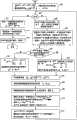
在该美国专利中检测发射信号的处理流程如图2所示,包括以下步骤:The processing flow of detecting the emission signal in this US patent is shown in Figure 2, including the following steps:

步骤201:利用信道矩阵H相关的广义逆矩阵,通过迭代的方法得到矩阵P1/2和Qα的初始值。包括以下201-1~201-3的步骤:Step 201: Using the generalized inverse matrix related to the channel matrix H, the initial values of the matrix P1/2 and Qα are obtained through an iterative method. Including the following steps from 201-1 to 201-3:

201-1:将P1/2初始化成M×M的单位矩阵I的

Figure S06165505120060328D000026
倍,即P01/2=1aI,其中α是基于发射信号的信噪比的常数;将Qα初始化成N×M的零矩阵,即Q0=0(N×M)。用i表示迭代阶数,设i的初始值为1,进行N次迭代。201-1: Initialize P1/2 to the M×M identity matrix I
Figure S06165505120060328D000026
times, that isP 0 1 / 2 = 1 a I , where α is a constant based on the signal-to-noise ratio of the transmitted signal; Qα is initialized to an N×M zero matrix, that is, Q0 =0(N×M ). Use i to represent the iteration order, set the initial value of i to 1, and perform N iterations.

201-2:根据

Figure S06165505120060328D000028
、Qi-1以及信道矩阵H定义一个第i(1≤i≤N)次迭代过程中的(N+M+1)×(M+1)的矩阵X,Xi=1HiPi-11/20MPi-11/2-eiQi-1,其中,0M是所有的M项都为零的列向量,ei是第i个N维单位列向量,Hi是信道矩阵的第i行。201-2: According to
Figure S06165505120060328D000028
, Qi-1 and channel matrix H define a matrix X of (N+M+1)×(M+1) in the i-th (1≤i≤N) iteration process, x i = 1 h i P i - 1 1 / 2 0 m P i - 1 1 / 2 - e i Q i - 1 , Among them, 0M is a column vector in which all M items are zero, ei is the i-th N-dimensional unit column vector, and Hi is the i-th row of the channel matrix.

通过酉变换将所述矩阵Xi块下三角化,即通过变换将矩阵的第一行除了第一列元素以外的元素全变为零,变换后得到矩阵YiYi=×0MT×Pi1/2×Qi,其中,矩阵Yi的第一行的后M项全为零,变换后的矩阵Yi中包括第i次迭代后得到的

Figure S06165505120060328D000032
和Qi。The matrix Xi is triangulated down by unitary transformation, that is, the elements in the first row of the matrix except the first column elements are all changed to zero by transformation, and the matrix Yi obtained after transformation is Y i = × 0 m T ×P i 1 / 2 × Q i , where the last M items of the first row of the matrix Yi are all zeros, and the transformed matrix Yi includes the
Figure S06165505120060328D000032
and Qi .

201-3:i的值增加1,并判断i是否等于N,如果是,则得到N次迭代后的P1/2和Qα的初始值;否则,返回步骤201-2,进行下一次迭代。201-3: Increase the value of i by 1, and judge whether i is equal to N, if yes, obtain the initial values of P1/2 and Qα after N iterations; otherwise, return to step 201-2 for the next iteration .

根据上述迭代方法得到的p1/2的初始值不是三角形矩阵。The initial value of p1/2 obtained according to the above iterative method is not a triangular matrix.

待检测信号的阶数用J表示,J设置为M,然后进入下面检测发射信号的流程中。The order of the signal to be detected is represented by J, and J is set to M, and then enters the following process of detecting the transmitted signal.

步骤202:通过矩阵P1/2决定下一个被检测的发射信号,在待检测发射信号中接收信噪比最好的一个接收信号为下一次被检测的发射信号。在p1/2矩阵中最小长度的行向量对应接收信噪比最好的最优检测发射信号。Step 202: Determine the next transmitted signal to be detected through the matrix P1/2 , and the received signal with the best received signal-to-noise ratio among the transmitted signals to be detected is the next transmitted signal to be detected. The row vector with the smallest length in the p1/2 matrix corresponds to the optimally detected transmitted signal with the best received signal-to-noise ratio.

步骤203:由P1/2和Qα计算步骤202中所确定的下一个被检测的发射信号的迫零向量,包括以下203-1~203-3的步骤:Step 203: Calculate the zero-forcing vector of the next detected transmission signal determined instep 202 by P1/2 and Qα , including the following steps 203-1 to 203-3:

203-1:在P1/2矩阵中交换步骤202中确定的最小长度行向量所在的行与最后一行,并重新编号信号向量的索引,同时,交换信道矩阵H中对应步骤202中选择的最优检测发射信号的列和最后一列。203-1: Exchange the row and the last row where the minimum length row vector determined instep 202 is located in the P1/2 matrix, and renumber the index of the signal vector, and at the same time, exchange the channel matrix H corresponding to the most Optimal detection of the emitted signal's column and the last column.

203-2:通过酉变换∑,块上三角化上述p1/2矩阵,酉变换后得到的p1/2的最后一行中除了最后一项之外全为零;对矩阵Qα通过所述酉变换∑变换后,Qα的值被更新成Qα∑。203-2: Through the unitary transformation Σ, the above p1/2 matrix is triangulated on the block, and the last row of p1/2 obtained after the unitary transformation is all zero except for the last item; for the matrix Qα , pass the After unitary transformation Σ transformation, the value of Qα is updated to Qα Σ.

203-3:计算待检测发射信号的迫零向量,迫零向量为p1/2矩阵的最后一行的最后一项与Qα的共轭转置的最后一行的乘积。203-3: Calculate the zero-forcing vector of the transmitted signal to be detected, the zero-forcing vector is the conjugate transpose of the last item in the last row of the p1/2 matrix and Qα The product of the last row of .

步骤204:根据所得到的迫零向量和接收信号向量

Figure S06165505120060328D000034
的乘积得到待检测发射信号的估计值后,对估计值进行量化得到
Figure S06165505120060328D000035
Step 204: According to the obtained zero-forcing vector and received signal vector
Figure S06165505120060328D000034
After obtaining the estimated value of the transmitted signal to be detected by the product of , the estimated value is quantified to obtain
Figure S06165505120060328D000035

步骤205:用p1/2自身的一个子矩阵代替P1/2,以及用Qα自身的一个子矩阵代替Qα;从接收信号中删除已检测发射信号的影响,得到x→(J-1)=x→J-hJs^J.将待检测发射信号的阶数减一,即J的值减1。Step 205: replace P1/2 with a sub-matrix of p1/2 itself, and replace Qα with a sub-matrix of Qα itself; remove the influence of the detected transmitted signal from the received signal to obtain x &Right Arrow; ( J - 1 ) = x &Right Arrow; J - h J the s ^ J . The order of the transmitted signal to be detected is reduced by one, that is, the value of J is reduced by one.

步骤206:判断是否已检测到最后一个发射信号,即J是否等于零,如果是,则结束本流程;否则返回执行步骤202,按照上述方法检测下一个信号。Step 206: Judging whether the last transmitted signal has been detected, that is, whether J is equal to zero, if yes, then end the process; otherwise, return tostep 202, and detect the next signal according to the above method.

2004年在IEEE Signal Processing letters的第9期第11卷中已公开发表的″An Improved Square-root Algorithm for BLAST″文章中提出,迫零向量可通过与信道矩阵H相关的最小均方误差滤波器得到,更具体的,在该方法中,只需要计算P1/2的初始值,每一个信号检测中所需的迫零向量是通过更新的P1/2矩阵中的一个元素和一个向量以及原始尺寸或缩小的信道矩阵H的乘积求得,即迫零向量的计算公式为GM=pM1/2(PM(M-1)/2)H(pM1/2)HHH,其中P1/2的意义以及初始化过程同美国专利所述内容,pM1/2和PM(M-1)/2分别是上述步骤203-2所述的通过酉变换∑块上三角化后的P1/2矩阵中的一个元素和一个向量,具体的,因为203-2所述的通过酉变换∑块上三角化后的P1/2的最后一行除了最后一项元素之外全为零,表示为P1×2=×PM(M-1)/20m-1TpM1/2,其中×表示当前不关心的一个子矩阵;pM1/2是P1/2的最后一行的最后一项,即该行唯一的非零项;PM(M-1)/2是在P1/2的最后一列中删除最后的一项,即删除pm1/2,所得到的列向量。In 2004, it was proposed in the article "An Improved Square-root Algorithm for BLAST" published in Volume 11 of Issue 9 of IEEE Signal Processing letters that the zero-forcing vector can pass through the minimum mean square error filter related to the channel matrix H More specifically, in this method, only the initial value of P1/2 needs to be calculated, and the zero-forcing vector required in each signal detection is obtained by updating an element and a vector in the P1/2 matrix and The product of the original size or the reduced channel matrix H is obtained, that is, the calculation formula of the zero-forcing vector is G m =p m 1 / 2 ( P m ( m - 1 ) / 2 ) h (p m 1 / 2 ) h h h , Wherein, the meaning of P1/2 and the initialization process are the same as those described in the U.S. patent, and pM1/2 and PM(M-1)/2 are respectively the upper triangulation by unitary transformation Σ block described in the above step 203-2 An element and a vector in the post-P1/2 matrix, specifically, because the last row of P1/2 triangulated by the unitary transformation ∑ block described in 203-2 is all except the last element is zero, expressed asP 1 × 2 = × P m ( m - 1 ) / 2 0 m - 1T p m 1 / 2 , Among them, × represents a sub-matrix that is not currently concerned; pM1/2 is the last item of the last row of P1/2 , that is, the only non-zero item in this row; PM(M-1)/2 is in P Delete the last item in the last column of1/2 , that is, delete pm1/2 , the resulting column vector.

综上所述,现有技术中美国专利和IEEE的文章提出的多天线数字无线通信系统中信号检测方法存在以下缺点:In summary, the signal detection method in the multi-antenna digital wireless communication system proposed by the US patent and the IEEE article in the prior art has the following disadvantages:

(1)美国专利和IEEE文章中利用M×M的矩阵递推计算M个被检测发射信号的P1/2的初始值,由于每一次递推中的中间结果为M×M的矩阵,因此计算P1/2的初始值所需的计算量较大。(1) In the U.S. patent and IEEE article, the initial value of P1/2 of the M detected transmitted signals is calculated by using the matrix recursion of M×M. Since the intermediate result in each recursion is a matrix of M×M, therefore The computation required to calculate the initial value of P1/2 is relatively large.

(2)美国专利和IEEE文章中计算迫零向量所需的P1/2的初始值矩阵的元素通常都是非零的。这将会导致信号检测过程中计算量较大。(2) The elements of the initial value matrix of P1/2 required for calculating the zero-forcing vector in US patents and IEEE articles are usually non-zero. This will lead to a large amount of calculation in the signal detection process.

(3)美国专利和IEEE文章中检测接收信号过程中,每次将P1/2转换成块上三角形。从转换成块上三角形的P1/2中取其子矩阵用以下一个信号的检测,由于子矩阵并非是块上三角形,因此,又将子矩阵转换成块上三角形后才能得到检测信号所需的迫零向量。因此,在信号检测中需要比较大的计算量。(3) In the process of detecting the received signal in the US patent and the IEEE article, P1/2 is converted into an upper triangle every time. Take the sub-matrix from the P1/2 that is converted into a triangle on the block to detect the next signal. Since the sub-matrix is not a triangle on the block, the detection signal can only be obtained after converting the sub-matrix into a triangle on the block. The zero-forcing vector of . Therefore, a relatively large amount of calculation is required in signal detection.

(4)IEEE文章中提出的信号检测中,由GM=pM1/2(PM(M-1)/2)H(pM1/2)HHH计算迫零向量,再用迫零向量和接收信号向量相乘得到检测信号的估计,然后从接收信号中消除已检测信号的干扰,即通过x→(J-1)=x→J-hJs^J更新接收信号向量,用于下一个信号的检测。上述计算GM=pM1/2(PM(M-1)/2)H(pM1/2)HHH的迫零向量需要较多的计算量。(4) In the signal detection proposed in the IEEE article, by G m =p m 1 / 2 ( P m ( m - 1 ) / 2 ) h (p m 1 / 2 ) h h h Calculate the zero-forcing vector, and then multiply the zero-forcing vector and the received signal vector to obtain an estimate of the detected signal, and then eliminate the interference of the detected signal from the received signal, that is, by x &Right Arrow; ( J - 1 ) = x &Right Arrow; J - h J the s ^ J Update the received signal vector for the detection of the next signal. The above calculation G m =p m 1 / 2 ( P m ( m - 1 ) / 2 ) h (p m 1 / 2 ) h h h The zero-forcing vector of needs more computation.

发明内容Contents of the invention

有鉴于此,本发明的主要目的在于提供一种多天线数字无线通信系统中信号检测的方法,以较少的计算量实现信号检测。In view of this, the main purpose of the present invention is to provide a method for signal detection in a multi-antenna digital wireless communication system, so as to realize signal detection with less calculation amount.

为了达到上述目的,本发明提供一种多天线数字无线通信系统中信号检测的方法,在MIMO系统中检测至少两个发射信号,所述发射信号由发射端各个不同的发射天线分别发射并经过一个信道到达接收端,其特征在于,该方法包括以下步骤:In order to achieve the above object, the present invention provides a method for signal detection in a multi-antenna digital wireless communication system. In a MIMO system, at least two transmission signals are detected, and the transmission signals are respectively transmitted by different transmission antennas at the transmission end and passed through a The channel reaches the receiving end, characterized in that the method comprises the following steps:

a)接收端的至少两个接收天线接收所述发射信号,获得至少两个接收信号;a) at least two receiving antennas at the receiving end receive the transmitting signal to obtain at least two receiving signals;

b)接收端根据接收信号进行信道估计,得到由发射天线和接收天线之间的信道系数组成的信道矩阵H;b) The receiving end performs channel estimation according to the received signal, and obtains a channel matrix H composed of channel coefficients between the transmitting antenna and the receiving antenna;

c)利用信道矩阵H计算出所有发射信号中的部分发射信号的估计误差协方差矩阵的分解因子矩阵,然后利用信道矩阵H,并以部分发射信号的估计误差协方差矩阵的分解因子矩阵作为子矩阵,递推求得包括所述部分发射信号且个数多于所述部分发射信号个数的发射信号的估计误差协方差矩阵的分解因子矩阵;c) Use the channel matrix H to calculate the decomposition factor matrix of the estimated error covariance matrix of some transmitted signals in all transmitted signals, and then use the channel matrix H, and use the decomposition factor matrix of the estimated error covariance matrix of some transmitted signals as a sub- Matrix, recursively obtaining a decomposition factor matrix of the estimated error covariance matrix of the transmitted signal including the partial transmitted signal and the number of transmitted signals is greater than the number of the partial transmitted signal;

d)使用步骤c所得到的包括所述部分发射信号且个数多于所述部分发射信号个数的发射信号的估计误差协方差矩阵的分解因子矩阵计算迫零向量,通过消除干扰检测步骤c中所述的包括部分发射信号且个数多于所述部分发射信号个数的发射信号。d) Calculate the zero-forcing vector by using the decomposed factor matrix of the estimated error covariance matrix of the estimated error covariance matrix of the transmitted signal including the part of the transmitted signal and the number of the transmitted signal is greater than the number of the part of the transmitted signal obtained in step c, by eliminating the interference detection step c The transmission signals mentioned in include a part of the transmission signals and the number of the transmission signals is more than the number of the part of the transmission signals.

所述步骤b和步骤c之间进一步包括:设置检测至少两个发射信号的先后顺序;The step between step b and step c further includes: setting the order of detecting at least two transmitted signals;

所述步骤c包括:Said step c comprises:

c21)利用所设置的检测顺序中最后被检测的一个发射信号对应的信道矩阵,计算所述最后被检测的一个发射信号的估计误差的协方差矩阵的分解因子矩阵;c21) Using the channel matrix corresponding to the last detected transmission signal in the set detection order, calculate the decomposition factor matrix of the covariance matrix of the estimation error of the last detected transmission signal;

c22)利用与所设置的检测顺序中最后被检测的m个发射信号对应的信道矩阵,并以上一次递推或者步骤c21得到的最后被检测的m-1个发射信号的估计误差协方差矩阵的分解因子矩阵作为子矩阵,递推所述最后被检测的m个发射信号的估计误差协方差矩阵的分解因子矩阵,如果已得到所有发射信号的估计误差协方差矩阵的分解因子矩阵,则结束本步骤,否则m的值加1,返回步骤c22;c22) using the channel matrix corresponding to the last detected m transmitted signals in the set detection order, and the estimated error covariance matrix of the last detected m-1 transmitted signals obtained by the previous recursion or step c21 Decomposing the factor matrix as a sub-matrix, recursing the decomposing factor matrix of the estimated error covariance matrix of the last detected m transmitted signals, if the decomposed factor matrix of the estimated error covariance matrix of all transmitted signals has been obtained, then end this Step, otherwise the value of m is increased by 1, and returns to step c22;

其中,m的初始值设为2。Among them, the initial value of m is set to 2.

所述步骤d包括:Said step d comprises:

d1)在待检测发射信号中选择当前被检测的一个发射信号,利用步骤c得到的所有发射信号的估计误差协方差矩阵的分解因子矩阵、信道矩阵H以及接收信号得到对所述当前被检测的一个发射信号的估计值;d1) Select a currently detected transmitted signal among the transmitted signals to be detected, and use the decomposition factor matrix of the estimated error covariance matrix of all transmitted signals obtained in step c, the channel matrix H and the received signal to obtain the current detected signal. an estimate of the transmitted signal;

d2)利用步骤d1得到的当前被检测的一个发射信号的估计值计算对检测后续待检测发射信号的干扰值,消除所述当前被检测的一个发射信号对检测后续待检测发射信号的干扰;d2) Using the estimated value of a currently detected transmission signal obtained in step d1 to calculate an interference value for detecting a subsequent transmission signal to be detected, and eliminate the interference of the currently detected transmission signal to the detection of a subsequent transmission signal to be detected;

d3)重复步骤d1、d2,直到检测到所有待检测发射信号。d3) Steps d1 and d2 are repeated until all emission signals to be detected are detected.

本发明提供的信号检测的方法中,利用从部分发射信号的P1/2递推所有发射信号的P1/2的方法计算求迫零向量所需的P1/2的初始值,因此能够减少计算P1/2的初始值的计算量,而且便于硬件实现。本发明可以使递推过程中的P1/2具有完全三角形形式或通过简单行和列交换能成为完全三角形的形式,得到完全三角形或通过简单行和列交换能成为完全三角形的P1/2的初始值,因此能够减少信号检测过程中的计算量。而且,本发明在信号检测之前,首先对接收信号进行预匹配滤波变换,且迫零向量仅由P1/2计算,因此能够减少信号检测的计算量。本发明提供的信号检测过程中,能够利用很多中间过程的结果,因此能够进一步减少计算量。本发明还可以利用从部分发射信号的估计误差协方差矩阵的LDLT分解因子矩阵递推所有发射信号的估计误差协方差矩阵的LDLT分解因子矩阵后,计算求迫零向量所需的P1/2的初始值,消除了开平方根导致的误差和延迟的影响。In the signal detection method provided by the present invention, the initial value of P1/2 required for forcing the zero vector is calculated by using the method of recursively deriving P1/2 of all transmitted signals from P1/2 of part of the transmitted signal, so it can The calculation amount for calculating the initial value of P1/2 is reduced, and it is convenient for hardware implementation. The present invention can make P1/2 in the recursive process have a complete triangular form or can become a complete triangular form through simple row and column exchange, and obtain complete triangle or P1/2 that can become a complete triangle through simple row and column exchange The initial value of , so it can reduce the amount of calculation in the signal detection process. Moreover, before the signal detection, the present invention first performs pre-matching filter transformation on the received signal, and the zero-forcing vector is only calculated by P1/2 , so the calculation amount of signal detection can be reduced. In the signal detection process provided by the present invention, the results of many intermediate processes can be used, so the calculation amount can be further reduced. The present invention can also use the LDLT decomposition factor matrix of the estimated error covariance matrix of all transmitted signals from the LDLT decomposition factor matrix of the estimated error covariance matrix of part of the transmitted signal to calculate the requiredP1 for forcing the zero vector The initial value of/2 eliminates the error and delay caused by the square root.

下面以信号检测中需要的乘法个数分析本发明相对现有技术的计算速度的提高,包括以下几个方面:The improvement of the calculation speed of the present invention relative to the prior art is analyzed below with the number of multiplications required in the signal detection, including the following aspects:

(1)比较本发明和现有技术中计算P们的初始值的计算量。(1) Comparing the calculation amount of calculating the initial value of P in the present invention and the prior art.

首先,分析本发明中计算P1/2的初始值的计算量。First, the calculation amount of calculating the initial value of P1/2 in the present invention is analyzed.

利用H计算R矩阵需要

Figure S06165505120060328D000071
个乘法。Using H to calculate the R matrix requires
Figure S06165505120060328D000071
multiplication.

在递推P1/2过程中计算βm-1(tm)=1λ1(tm)-((P(tm-1)(m-1)/2)HYm-1(tm))H((P(tm-1)(m-1)/2)HYm-1(tm))和计算Vm-1(tm)=-βm-1(tm)P(tm-1)(m-1)/2(P(tm-1)(m-1)/2)HYm-1(tm)的计算过程中,让ηm-1=(P(tm-1)(m-1)/2)HYm-1(tm),使得充分利用中间结果避免重复的运算,则上面的计算量为:计算βm-1(tm)=1λ1(tm)-ηm-1Hηm-1Vm-1(tm)=-βm-1(tm)P(tm-1)(m-1)/2ηm-1的计算量。计算ηm-1=(P(tm-1)(m-1)/2)HYm-1(tm)每一次需要

Figure S06165505120060328D000078
个乘法,计算βm-1(tm)=1λ1(tm)-ηm-1Hηm-1需要m个乘法,而计算Vm-1(tm)=-βm-1(tm)P(tm-1)(m-1)/2ηm-1需要个乘法,那么总共需要Σm=1M-1m(m+1)2+m+m(m+1)2+m≈Σm=1M-1m2≈13M3个乘法。Computed during recursion P1/2 β m - 1 ( t m ) = 1 λ 1 ( t m ) - ( ( P ( t m - 1 ) ( m - 1 ) / 2 ) h Y m - 1 ( t m ) ) h ( ( P ( t m - 1 ) ( m - 1 ) / 2 ) h Y m - 1 ( t m ) ) and calculate V m - 1 ( t m ) = - β m - 1 ( t m ) P ( t m - 1 ) ( m - 1 ) / 2 ( P ( t m - 1 ) ( m - 1 ) / 2 ) h Y m - 1 ( t m ) During the calculation process, let η m - 1 = ( P ( t m - 1 ) ( m - 1 ) / 2 ) h Y m - 1 ( t m ) , making full use of intermediate results to avoid repeated operations, then the above calculation amount is: calculation β m - 1 ( t m ) = 1 λ 1 ( t m ) - η m - 1 h η m - 1 and V m - 1 ( t m ) = - β m - 1 ( t m ) P ( t m - 1 ) ( m - 1 ) / 2 η m - 1 calculation amount. calculate η m - 1 = ( P ( t m - 1 ) ( m - 1 ) / 2 ) h Y m - 1 ( t m ) every need
Figure S06165505120060328D000078
multiplication, calculate β m - 1 ( t m ) = 1 λ 1 ( t m ) - η m - 1 h η m - 1 requires m multiplications, while computing V m - 1 ( t m ) = - β m - 1 ( t m ) P ( t m - 1 ) ( m - 1 ) / 2 η m - 1 need multiplications, then a total of Σ m = 1 m - 1 m ( m + 1 ) 2 + m + m ( m + 1 ) 2 + m ≈ Σ m = 1 m - 1m 2 ≈ 1 3m 3 multiplication.

因此,本发明计算P1/2需要

Figure S06165505120060328D0000713
个乘法。Therefore, the present invention calculates P1/2 needs
Figure S06165505120060328D0000713
multiplication.

利用LDLT分解因子矩阵L、D矩阵递推计算求P1/2的初始值的计算量近似与上述的计算量。Using LDLT to decompose factor matrices L and D matrix recursively calculates the calculation amount of the initial value of P1/2 , which is approximately the same as the above calculation amount.

然后,分析现有技术中的IEEE文章中提供的技术方案中的计算量。Then, the calculation amount in the technical solution provided in the IEEE article in the prior art is analyzed.

计算P1/2的初始值需要N(M2+2(M+1)2)=3NM2+O(MN)个复数乘法。Computing the initial value of P1/2 requires N (m 2 + 2 ( m + 1 ) 2 ) = 3N m 2 + o ( MN ) complex multiplication.

而在信号检测的迭代过程中,每次迭代找到一个最佳接收信噪比的发射信号加以检测,并计算迫零向量,其中主要的计算量在于计算Pm/2∑和计算迫零向量

Figure S06165505120060328D0000715
的步骤。每一次迭代计算Pm/2∑需要2m2。个复数乘法,计算迫零向量需要m(N+1)+1个复数乘法。从而,信号检测的M次迭代总共需要Σm=1M(2m2+m(N+1)+1)=23M3+12M2+O(M2+MN)个复数乘法。In the iterative process of signal detection, each iteration finds a transmitted signal with the best received signal-to-noise ratio for detection, and calculates the zero-forcing vector. The main calculation amount is to calculate Pm/2 Σ and zero-forcing vector
Figure S06165505120060328D0000715
A step of. Computing Pm/2 ∑ for each iteration requires 2m2 . complex multiplications, calculating the zero-forcing vector requires m(N+1)+1 complex multiplications. Thus, M iterations of signal detection require a total of Σ m = 1 m ( 2m 2 + m ( N + 1 ) + 1 ) = 2 3m 3 + 1 2m 2 + o (m 2 + MN ) complex multiplication.

把上述两步的计算量累加,总共需要23M3+72M2N+O(M2+MN)个复数乘法,如果M=N,则总共需要个复数乘法。Adding up the calculation amount of the above two steps, a total of 2 3m 3 + 7 2 m 2 N + o (m 2 + MN ) complex multiplications, if M=N, a total of complex multiplication.

综上所述,本发明计算P1/2。需要

Figure S06165505120060328D000084
个乘法,而IEEE文章提出的技术需要3NM2个。设M=N,本发明需要的乘法是个乘法,IEEE文章提出的技术需要3M3个乘法,本发明在这一步的计算量是IEEE文章提出的技术的28%。In summary, the present invention calculates P1/2 . need
Figure S06165505120060328D000084
multiplications, while the technique proposed in the IEEE article requires2 of 3NM. Suppose M=N, the multiplication that the present invention needs is multiplication, the technology proposed by the IEEE article needs 3M3 multiplications, and the calculation amount of the present invention in this step is 28% of the technology proposed by the IEEE article.

IEEE文章提出的技术共需要

Figure S06165505120060328D000086
个乘法,假设本发明其它的步骤与IEEE文章提出的技术完全一致时本发明需要256M3-(3M3-56M3)=2M3个乘法,则本发明的速度相对IEEE文章提出的技术提速(256M3)/(2M3)=2.08倍。Technical Requirements Raised by IEEE Articles
Figure S06165505120060328D000086
multiplication, assuming that the other steps of the present invention are fully consistent with the technology proposed in IEEE articles, the present invention needs 25 6 m 3 - ( 3 m 3 - 5 6 m 3 ) = 2m 3 multiplication, the speed of the present invention is accelerated relative to the technology proposed in the IEEE article ( 25 6 m 3 ) / ( 2 m 3 ) = 2.08 times.

(2)本发明求得的初始的P1/2=pM/2是完全上三角的矩阵。(2) The initial P1/2 =pM/2 obtained by the present invention is a complete upper triangular matrix.

在信号检测的迭代过程中,如果使用本发明提供的基于Givens Rotation的正交变换∑,将通过行交换变成完全上三角的Pm/2认为是完全上三角的矩阵,则由Pm/2Σ=P(m-1)/2P→m(m-1)/20m-1Tpm1/2求得的P(m-1)/2也是所述完全上三角的矩阵;从而本发明所有的Pm/2(m=M,M-1,...,2,1)都是所述完全上三角的矩阵,众所周知,计算Pm/2∑的时候,如果Pm/2是完全上三角的,有一半的元素是零,则可以节省大约一半的计算量。而且根据本发明提供的基于较少数目的Givens Rotation的正交变换,则又能减少计算量。In the iterative process of signal detection, if the orthogonal transformation Σ based on Givens Rotation provided by the present invention is used, the Pm/2 that will become completely upper triangular by row exchange is considered to be a complete upper triangular matrix, then by P m / 2 Σ = P ( m - 1 ) / 2 P &Right Arrow; m ( m - 1 ) / 2 0 m - 1T p m 1 / 2 The obtained P(m-1)/2 is also the matrix of the complete upper triangle; thus all Pm/2 (m=M, M-1, ..., 2, 1) of the present invention are described Completely upper triangular matrix, as we all know, when calculating Pm/2 ∑, if Pm/2 is completely upper triangular, and half of the elements are zero, about half of the calculation amount can be saved. Moreover, according to the orthogonal transformation based on a small number of Givens Rotations provided by the present invention, the amount of calculation can be reduced.

在信号检测的迭代过程中,如果使用本发明提供的基于Householder的正交变换,则一次正交变换后得到的用于下一次迭代的矩阵是块上三角形矩阵,不一定是完全上三角的矩阵,但是矩阵中仍然有很多零元素,从而可以近似的认为本发明的方法可以节约一半的计算量。In the iterative process of signal detection, if the Householder-based orthogonal transformation provided by the present invention is used, the matrix used for the next iteration obtained after one orthogonal transformation is a block upper triangular matrix, not necessarily a complete upper triangular matrix , but there are still many zero elements in the matrix, so it can be approximately considered that the method of the present invention can save half of the calculation amount.

IEEE文章提出的技术中需要2m2个乘法计算Pm/2∑,本发明只需要m2个乘法;IEEE文章提出的技术总共需要Σm=1M2m2=23M3个乘法计算Pm/2∑,本发明只需要Σm=1Mm2=13M3个乘法。Need 2m2 multiplications to calculate Pm/2 ∑ in the technology that IEEE article proposes, the present invention only needs m2 multiplications; The technology that IEEE article proposes needs in total Σ m = 1 m 2m 2 = 2 3m 3 multiplication calculation Pm/2 ∑, the present invention only needs Σ m = 1 mm 2 = 1 3m 3 multiplication.

IEEE文章提出的技术中,在每一次迭代中计算迫零向量需要m(N+1)+1个复数乘法;而本发明的迫零向量是Gm=pm1/2·[(P→m(m-1)/2)H(pm1/2)H],只需要m个乘法。所以,IEEE文章提出的技术计算迫零向量需要Σm=1M(m(N+1)+1)≈12M2N个乘法,本发明只需要Σm=1Mm=12M2个乘法,相当于节省了

Figure S06165505120060328D000096
个乘法。In the technology proposed by the IEEE article, m(N+1)+1 complex number multiplications are needed to calculate the zero-forcing vector in each iteration; and the zero-forcing vector of the present invention is G m =p m 1 / 2 &Center Dot; [ ( P &Right Arrow; m ( m - 1 ) / 2 ) h (p m 1 / 2 ) h ] , only m multiplications are required. Therefore, the technique proposed in the IEEE article to calculate the zero-forcing vector requires Σ m = 1 m ( m ( N + 1 ) + 1 ) ≈ 1 2 m 2 N multiplication, the present invention only needs Σ m = 1 m m = 1 2m 2 multiplication, which is equivalent to saving
Figure S06165505120060328D000096
multiplication.

本发明的速度相对IEEE文章提出的技术提速为The speed of the present invention relative to the technical speed-up that IEEE article proposes is

Figure S06165505120060328D000097

(3)本发明中在计算初始的p1/2=Pm/2的过程中,还求得了M个发射天线在接收端依照一个tM,tM-1,…,tm,…,t2,t1的先后顺序被检测时对应的各个Pm/2(m=M,M-1…,2,1)。如果实际的最优检测顺序与这个顺序相同或者相似度很高,则求得的各个Pm/2可以重复利用,省去了利用正交变换∑求Pm/2∑的步骤。通常的V-BLAST工作的慢衰落信道(slow fading channel)是近似平稳的,在这样的信道下,尽管每个数据帧对应的信道矩阵有了变化从而相应的迫零向量也需要改变,但是先后的各个数据帧的最优检测顺序的变化很缓慢,甚至不变。如果这样,完全不需要计算Pm/2∑,因此个乘法也可以省略,则本发明的速度相对IEEE文章提出的技术提速进一步为(3) In the process of calculating the initial p1/2 =Pm/2 in the present invention, it is also obtained that the M transmitting antennas at the receiving end follow a tM , tM-1 ,..., tm ,..., Each Pm/2 (m=M, M-1..., 2, 1) corresponding to the order of t2 and t1 is detected. If the actual optimal detection sequence is the same as this sequence or has a high degree of similarity, each obtained Pm/2 can be reused, and the step of obtaining Pm/2 Σ by using the orthogonal transformation Σ is omitted. The slow fading channel (slow fading channel) of the usual V-BLAST work is approximately stable. Under such a channel, although the channel matrix corresponding to each data frame has changed and the corresponding zero-forcing vector needs to be changed, but successively The optimal detection order of each data frame of the change is very slow, or even constant. If so, there is no need to calculate Pm/2 ∑ at all, so The three multiplications can also be omitted, and then the speed of the present invention is further increased as compared to the technical speed-up proposed by the IEEE article.

Figure S06165505120060328D000099

综上所述,本发明的速度相对IEEE文章提出的技术提速为3.57到5.00倍,达到或逼近5.00的提速的条件为预先设置的M个发射天线在接收端被检测的先后顺序tM,tM-1,…,tm,…,t2,t1与实际的最优检测顺序相同或比较接近。In summary, the speed of the present invention is 3.57 to 5.00 times faster than the technology proposed in the IEEE article, and the condition for reaching or approaching the speed-up of 5.00 is the pre-set sequence tM , t of the M transmitting antennas being detected at the receiving endM-1 , . . . , tm , . . . , t2 , t1 are the same as or relatively close to the actual optimal detection sequence.

附图说明Description of drawings

图1所示为多天线数字无线通信系统框图;Figure 1 shows a block diagram of a multi-antenna digital wireless communication system;

图2所示为现有技术中检测接收信号的处理流程图;Fig. 2 shows the processing flowchart of detecting received signal in the prior art;

图3所示为本发明第一实施例中求P1/2的初始值的流程图;Fig. 3 shows the flowchart of seeking the initial value of P1/2 in the first embodiment of the present invention;

图4所示为本发明第一实施例中计算迫零向量的迭代过程及信号检测流程图;Fig. 4 shows the iterative process and signal detection flow chart of calculating the zero-forcing vector in the first embodiment of the present invention;

图5所示为本发明第二实施例中求P1/2的初始值的流程图;Fig. 5 shows the flowchart of seeking the initial value of P1/2 in the second embodiment of the present invention;

图6所示为本发明第二实施例中计算迫零向量的迭代过程及信号检测流程图。FIG. 6 is a flow chart showing the iterative process of calculating the zero-forcing vector and the signal detection in the second embodiment of the present invention.

具体实施方式Detailed ways

为使本发明的目的、技术方案和优点更加清楚明白,下面举具体实施例,对本发明作进一步详细的说明。In order to make the object, technical solution and advantages of the present invention clearer, specific examples are given below to further describe the present invention in detail.

本发明使用图1所示的多天线数字无线通信系统,发射信号s1,...,sM分别通过M个不同的发射天线单元a-1,...,a-M发射;相应的接收信号x1,...,xN分别从N个不同的接收天线单元b-1,...,b-N接收。其中,发射信号s1,...,sM中的每个已经用一个预先设定的符号星座(symbol constellation)编码,从而,在接收端通过检测接收信号x1,...,xN得到的对发射信号的估计值

Figure S06165505120060328D000101
应当落入这个符号星座中。众所周知,接收端对某个发射信号的1个估计值判决成所述符号星座中的某个符号的过程,称为对发射信号估计值的量化(slicing)。The present invention uses the multi-antenna digital wireless communication system shown in Fig. 1, and transmits signals s1 , ..., sM through M different transmit antenna units a-1, ..., aM respectively; the corresponding received signal x1 , ..., xN are respectively received from N different receiving antenna units b-1, ..., bN. Wherein, each of the transmitted signals s1 , ..., sM has been encoded with a preset symbol constellation (symbol constellation), so that, at the receiving end, by detecting the received signals x1 , ..., xN The resulting estimate of the transmitted signal
Figure S06165505120060328D000101
Should fall into this sign constellation. As is well known, the process of determining an estimated value of a certain transmitted signal at the receiving end to be a certain symbol in the symbol constellation is called quantization (slicing) of the estimated value of the transmitted signal.

信道矩阵H是一个N×M的矩阵,表示为The channel matrix H is an N×M matrix expressed as

Figure S06165505120060328D000111

信道矩阵H是一个N×M复数矩阵,假定它在K个符号的时期内是常数。向量hn:(n=1,2,...,N)和h:m(m=1,2,...,M)的长度分别是M和N。其中,信道矩阵H包含的信道向量h:1,至h:M分别表示信道对M个传输信号中的每一个的影响。更明确的,信道向量h:m(m=1,2,…,M)包括信道矩阵项h1m至hNm,表示分别的在接收天线单元b-1至b-N中每一个上的,信道对发射信号占sm的影响。The channel matrix H is an NxM complex matrix which is assumed to be constant over a period of K symbols. The lengths of the vectors hn: (n=1, 2, ..., N) and h: m (m = 1, 2, ..., M) are M and N, respectively. Wherein, the channel vectors h: 1 to h: M contained in the channel matrix H respectively represent the influence of the channel on each of the M transmission signals. More specifically, the channel vector h:m (m=1, 2, ..., M) includes channel matrix entries h1m to hNm , representing the pair of channels at each of the receive antenna elements b-1 to bN, respectively The transmit signal accounts for the effect of sm .

在图1所示的系统中,发射信号的向量与接收信号的向量之间满足关系式X(k)=Σm=1Mh:msm(k)+w(k)=Hs(k)+w,其中k表示采样时刻,k=1,2,…,K。用向量形式表示上述关系为X→=Σm=1Mh:msm+w→=Hs→+w→,再把该式写为X→=s1·h:1+s2·h:2+...+sm·h:m+···+sM·h:M+W→的形式,可以清楚的看到各个发射信号对接收信号向量

Figure S06165505120060328D000115
的影响。In the system shown in Figure 1, the vector of the transmitted signal and the vector of the received signal satisfy the relation x ( k ) = Σ m = 1 m h : m the s m ( k ) + w ( k ) = Hs ( k ) + w , where k represents the sampling moment, k=1, 2,...,K. Express the above relationship in vector form as x &Right Arrow; = Σ m = 1 m h : m the s m + w &Right Arrow; = h the s &Right Arrow; + w &Right Arrow; , and then write this formula as x &Right Arrow; = thes 1 &Center Dot; h : 1 + thes 2 · h : 2 + . . . + the s m &Center Dot; h : m + &Center Dot; &Center Dot; &Center Dot; + the s m &Center Dot; h : m + W &Right Arrow; In the form of , it can be clearly seen that each transmitted signal pair received signal vector
Figure S06165505120060328D000115
Impact.

其中,x→=[x1,x2,...,xN]T是N维接收信号向量,s→=[s1,s2,...,sN]T是M维发射信号向量,w→=[w1,w2,...,wN]T是一个零均值复数的加性高斯白噪声(AWGN)向量,它的方差RWW=E{W→·W→H}=σw2IN×N。其中,TH分别的表示矩阵或者向量的转置和共轭转置,IN×N表示N×N单位矩阵。其中,假设加性噪声在时间域和空间域都统计独立。假设发射信号s1,s2,...,sM是不相关的,这意味着发射信号向量

Figure S06165505120060328D0001111
的互相关矩阵是对角的,即Rss=E{s→·s→H}=σs2IM×M.in, x &Right Arrow; = [ x 1 , x 2 , . . . , x N ] T is the N-dimensional received signal vector, the s &Right Arrow; = [ thes 1 , thes 2 , . . . , the s N ] T is the M-dimensional transmitted signal vector, w &Right Arrow; = [w 1 ,w 2 , . . . , w N ] T is a zero-mean complex additive white Gaussian noise (AWGN) vector, and its variance R WW = E. { W &Right Arrow; &Center Dot; W &Right Arrow; h } = σ w 2 I N × N . Wherein,T andH respectively represent the transpose and conjugate transpose of a matrix or a vector, and IN×N represents an N×N unit matrix. where, assuming additive noise Statistically independent in both time and space domains. Assuming that the transmitted signals s1 , s2 , ..., sM are uncorrelated, it means that the transmitted signal vector
Figure S06165505120060328D0001111
The cross-correlation matrix of is diagonal, that is, R ss = E. { the s &Right Arrow; &Center Dot; the s &Right Arrow; h } = σ the s 2 I m × m .

在图1所示的系统中,上述的M个发射信号s1,...,sM组成的向量可以先与一个矩阵或者一个以上矩阵相乘得到一个结果向量后,由各个发射天线分别发射所述结果向量的各项。在3GPP TR 25.876 V1.7.1中提出了虚拟天线(Virtual Antenna)的技术,该技术提供了多个虚拟天线端口,发射信号s1,s2,...,sM分别送到各个虚拟天线端口后,对发射信号向量依次乘以一个矩阵T和一个矩阵u得到结果向量→s~=U·T·s→的各项再分别送到各个物理天线端口发射。在这种情况下,表示多个发射信号与多个接收信号之间的关系的等效信道矩阵,为H~=H·U·T。此时,接收信号向量为x→=H·U·T·s→+w→=H~s→+w→In the system shown in Fig. 1, the vector composed of the above-mentioned M transmit signals s1 ,..., sM can be multiplied by a matrix or more than one matrix to obtain a result vector, which is then transmitted by each transmit antenna The terms of the result vector. In 3GPP TR 25.876 V1.7.1, the technology of virtual antenna (Virtual Antenna) is proposed, which provides multiple virtual antenna ports, and transmits signals s1 , s2 ,..., sM to each virtual antenna port respectively After that, the transmitted signal vector is multiplied by a matrix T and a matrix u to obtain the result vector &Right Arrow; the s ~ = u · T &Center Dot; the s &Right Arrow; The items are then sent to each physical antenna port for transmission. In this case, the equivalent channel matrix representing the relationship between multiple transmitted signals and multiple received signals is h ~ = h &Center Dot; u &Center Dot; T . At this time, the received signal vector is x &Right Arrow; = h &Center Dot; u &Center Dot; T &Center Dot; the s &Right Arrow; + w &Right Arrow; = h ~ the s &Right Arrow; + w &Right Arrow;

因此,利用虚拟天线技术时的接收信号向量与发射信号向量之间的关系X→=H~s→+w→,与M个发射信号直接送到M个发射天线发射的情况下的接收信号向量与发射信号向量之间的关系X→=H~s→+w→具有完全相同的形式。Therefore, the relationship between the received signal vector and the transmitted signal vector when using the virtual antenna technique x &Right Arrow; = h ~ the s &Right Arrow; + w &Right Arrow; , and the relationship between the received signal vector and the transmitted signal vector when M transmitted signals are directly sent to M transmitted antennas for transmission x &Right Arrow; = h ~ the s &Right Arrow; + w &Right Arrow; have exactly the same form.

本发明具体实施例中,以M个发射信号直接送到M个发射天线发射的情况为例,详细说明检测信号的方法。对于利用虚拟天线技术时的检测发射信号的方法,把信道矩阵H用等效信道矩阵代替即可。In a specific embodiment of the present invention, the method for detecting signals is described in detail by taking the case where M transmit signals are directly sent to M transmit antennas for transmission as an example. For the method of detecting transmitted signals when using virtual antenna technology, the channel matrix H is used as the equivalent channel matrix Just replace it.

发射信号的最小均方误差(MMSE)估计为→s^=(HH·H+αIM×M)-1HHx→,其中,符号-1表示求矩阵的逆矩阵,α为与发射信号的信噪比相关的常数,α=σω2σσ2The minimum mean square error (MMSE) of the transmitted signal is estimated as &Right Arrow; the s ^ = ( h h &Center Dot; h + α I m × m ) - 1 h h x &Right Arrow; , where the symbol -1 represents the inverse matrix of the matrix, α is a constant related to the signal-to-noise ratio of the transmitted signal, α = σ ω 2 σ σ 2

本发明所述的估计误差e=s→-→s^的协方差矩阵为把加性高斯白噪声的方差归一化为1的情况下的协方差矩阵,即E{(s→-→S^(s→-→s^)H}=(HH·H+αIM×M)-1记为P,并定义R=(HH·H+αIM×M),则有P=R-1。估计误差的协方差矩阵P的平方根矩阵记为P1/2。,则有P=P1/2(P1/2)。因此,发射信号的最小均方误差估计可以表示为→s^=P1/2(P1/2)HHHx→The estimation error described in the present invention e = the s &Right Arrow; - &Right Arrow; the s ^ The covariance matrix of is the covariance matrix when the variance of the additive Gaussian white noise is normalized to 1, that is E. { ( the s &Right Arrow; - &Right Arrow; S ^ ( the s &Right Arrow; - &Right Arrow; the s ^ ) h } = ( h h &Center Dot; h + α I m × m ) - 1 Denote as P, and define R = ( h h · h + αI m × m ) , Then there is P=R-1 . The square root matrix of the covariance matrix P of the estimation error is denoted as P1/2 . , then there is P=P1/2 (P1/2 ). Therefore, the minimum mean square error estimate of the transmitted signal can be expressed as &Right Arrow; the s ^ =P 1 / 2 (P 1 / 2 ) h h h x &Right Arrow;

如果在本发明定义的估计误差协方差矩阵上再乘以任何一个非零常数,也可以实现本发明提供的方法。针对在估计误差协方差矩阵乘以一个非零常数的情况,在使用迫零向量检测信号的步骤中,迫零向量的计算公式中也需要再乘一个与所述常数有关的值。If any non-zero constant is multiplied on the estimated error covariance matrix defined by the present invention, the method provided by the present invention can also be realized. For the case where the estimated error covariance matrix is multiplied by a non-zero constant, in the step of using the zero-forcing vector to detect the signal, the calculation formula of the zero-forcing vector also needs to be multiplied by a value related to the constant.

在本发明提供的信号检测中利用干扰消除(Interference Cancellation)技术,干扰消除技术的原理是:首先检测M个发射信号子s1,...,sM中选定的1个,使用这个已检测的发射信号的估计值,在接收信号向量中至少部分地消除已检测的发射信号的影响,这样把下一次信号检测的问题变成M-1个发射信号的检测的问题,以提高下一次检测的性能;在下一次检测M-1个发射信号过程中,继续引用上述干扰消除的方法,如此迭代M-1次,直到只剩下1个待检测的发射信号并把它检测出来为止。The interference cancellation (Interference Cancellation) technology is used in the signal detection provided by the present invention. The principle of the interference cancellation technology is: firstly detect one of the M transmission signal subs s1 , ..., sM selected, and use this already Estimates of the detected transmitted signals, at least partially canceling the influence of the detected transmitted signals in the received signal vector, thus turning the next signal detection problem into a detection problem of M-1 transmitted signals to improve the next Detection performance; in the process of detecting M-1 transmission signals next time, continue to refer to the above interference elimination method, and iterate M-1 times in this way, until there is only one transmission signal to be detected and it is detected.

假设由M个不同的发射天线发射的总共M个发射信号在接收端被检测的先后顺序用发射信号的序号表示为tM,tM-1,...,tm,...,t2,t1,则上述干扰消除技术的过程为:Assuming that a total of M transmit signals transmitted by M different transmit antennas are detected at the receiving end in the sequence expressed as tM , tM-1 , ..., tm , ..., t by the sequence numbers of the transmit signals2 , t1 , then the process of the above interference elimination technology is:

首先,设置初始值,即m的初始值设为M,初始的接收信号向量的值为

Figure S06165505120060328D000132
,初始的信道矩阵H(M)=H,初始的待检测发射信号向量为S→M=S→.First, set the initial value, that is, the initial value of m is set to M, and the initial received signal vector The value is
Figure S06165505120060328D000132
, the initial channel matrix H(M) = H, the initial signal vector to be detected is S &Right Arrow; m = S &Right Arrow; .

然后,通过迭代方法依次检测信号并进行干扰消除:检测第tm个发射信号得到该发射信号的估计值

Figure S06165505120060328D000134
,使用
Figure S06165505120060328D000135
在接收信号向量中至少部分地消除第tm个发射信号的影响。假定第tm个发射信号对接收信号向量的影响已经完全消除,则下一次的信号检测问题变成:X→m-1=Σi=1m-1h:tjsti+W→=H(m-1)s→m-1+w→,这里H(m-1)表示在信道矩阵H(m)中删除对应于第tm个发射信号的列以后得到的缩小的信道矩阵,而表示在发射信号向量
Figure S06165505120060328D000138
中删除本次迭代已经检测的发射信号tm。把m的值减1,继续所述的迭代过程,直到所有的M个发射信号都被检测出来。Then, the signals are sequentially detected by an iterative method and the interference is eliminated: detect the tmth transmitted signal to obtain the estimated value of the transmitted signal
Figure S06165505120060328D000134
,use
Figure S06165505120060328D000135
The influence of the tm -th transmitted signal is at least partially canceled in the received signal vector. Assuming that the influence of the tmth transmitted signal on the received signal vector has been completely eliminated, the next signal detection problem becomes: x &Right Arrow; m - 1 = Σ i = 1 m - 1 h : t j the s t i + W &Right Arrow; = h ( m - 1 ) the s &Right Arrow; m - 1 + w &Right Arrow; , Here H(m-1) represents the reduced channel matrix obtained after deleting the column corresponding to the tmth transmitted signal in the channel matrix H(m) , and represents the emitted signal vector
Figure S06165505120060328D000138
Delete the transmitted signal tm that has been detected in this iteration. The value of m is decremented by 1, and the iterative process is continued until all M transmitted signals are detected.

对于检测m-1个发射信号tm-1,...,t2,t1的问题,由上面的叙述,接收信号向量和发射信号向量的关系为:X→m-1=Σi=1m-1h:t1st1+w→=H(m-1)s→m-1+w→,则对应于m-1个发射信号tm-1,...,t2,t1的信道矩阵为H(m-1)。在检测m-1个发射信号tm-1,...,t2,t1的情况下,由信道矩阵H(m-1)可以得到下述各个矩阵,其方法与使用最初的信道矩阵H得到下述各个矩阵的方法相同,具体为:估计误差协方差矩阵为P(m-1)=((H(m-1))H·H(m-1)+αI(m-1)×(m-1))-1;估计误差协方差矩阵的逆矩阵为R(m-1)=(H(m-1))H·H(m-1)+αI(m-1)×(m-1);估计误差协方差矩阵P(m-1)的平方根矩阵为P(m-1)2,则有P(m-1)=P(m-1)/2(P(m-1)/2)H.For the problem of detecting m-1 transmitted signals tm-1 ,..., t2 , t1 , from the above description, the relationship between the received signal vector and the transmitted signal vector is: x &Right Arrow; m - 1 = Σ i = 1 m - 1 h : t 1 the s t 1 + w &Right Arrow; = h ( m - 1 ) the s &Right Arrow; m - 1 + w &Right Arrow; , Then the channel matrix corresponding to m-1 transmitted signals tm-1 , ..., t2 , t1 is H(m-1) . In the case of detecting m-1 transmitted signals tm-1 ,..., t2 , t1 , the following matrices can be obtained from the channel matrix H(m-1) , and the method is the same as using the original channel matrix H obtains the following matrices in the same way, specifically: the estimated error covariance matrix is P ( m - 1 ) = ( ( h ( m - 1 ) ) h &Center Dot; h ( m - 1 ) + α I ( m - 1 ) × ( m - 1 ) ) - 1 ; The inverse matrix of the estimated error covariance matrix is R ( m - 1 ) = ( h ( m - 1 ) ) h &Center Dot; h ( m - 1 ) + α I ( m - 1 ) × ( m - 1 ) ; The square root matrix of the estimated error covariance matrix P(m-1) is P(m-1)2 , then we have P ( m - 1 ) = P ( m - 1 ) / 2 ( P ( m - 1 ) / 2 ) h .

本发明提供的用于多天线数字无线通信系统中的信号检测过程中,包括求P1/2的初始值的递推过程和信号检测的迭代过程,分别为如下所述:In the signal detection process used in the multi-antenna digital wireless communication system provided by the present invention, it includes the recursive process and the iterative process of signal detection for the initial value of P1/2 , respectively as follows:

求P1/2的初始值的递推:计算对应于M个待检测发射信号的估计误差协方差矩阵的平方根矩阵P1/2的初始值的递推过程,计算所述P1/2的初始值是从较少待检测发射信号到较多待检测发射信号的递推,总体思路是:先设置所有M个发射信号在接收端被检测的先后顺序,记为tM,tM-1,tm,…,t2,t1,如果检测m-1(m=2,3,M)个发射信号tm-1,...,t2,t1情况下的估计误差协方差矩阵的平方根矩阵为P(m-1)/2,则通过P(m-1)/2递推得到检测m个发射信号tm,...,t2,t1情况下的估计误差协方差矩阵的平方根矩阵P(m)/2。因此,先计算一个发射天线情况下的估计误差协方差矩阵的平方根矩阵P(1)/2,然后由p(1)/2经过M-1次递推得到p(M)/2,即得到对应于M个待检测发射信号的估计误差协方差矩阵的平方根矩阵p1/2的初始值。Calculating the recursive process of the initial value of P1/2 : calculating the recursive process of the initial value of the square root matrix P1/2 corresponding to the estimated error covariance matrix of M transmission signals to be detected, and calculating the recursive process of the initial value of P1/2 The initial value is recursively from fewer transmission signals to be detected to more transmission signals to be detected. The general idea is: first set the order in which all M transmission signals are detected at the receiving end, denoted as tM , tM-1 , tm ,..., t2 , t1 , if m-1 (m=2, 3, M) transmitted signals are detected tm-1 ,..., t2 , the estimated error covariance in the case of t1 The square root matrix of the matrix is P(m-1)/2 , then the estimated error covariance in the case of detecting m transmitted signals tm ,..., t2 , t1 is obtained through P(m-1)/2 recursion The square root matrix P(m)/2 of the variance matrix. Therefore, first calculate the square root matrix P(1)/2 of the estimated error covariance matrix in the case of a transmitting antenna, and then obtain p(M)/2 from p(1)/2 through M-1 recursions, that is, Corresponding to the initial value of the square root matrix p1/2 of the estimated error covariance matrix of the M transmission signals to be detected.

信号检测的迭代:检测M个待检测的发射信号的迭代过程,检测发射信号是从较多待检测发射信号到较少待检测发射信号的递推,以求得一个最优检测顺序,并依照这个最优检测顺序依次检测这M个待检测的发射信号,总体思路是:由上述递推求得的对应于M个待检测发射信号的估计误差协方差矩阵的平方根矩阵p1/2=p(M)/2的初始值,根据某个标准,选择M个待检测发射信号中的1个进行检测,利用干扰消除的技术,在接收信号向量中消除这个已检测发射信号的影响,并由p(M)/2递推得到对应于M-1个待检测发射信号的p(M-1)/2。这样依次递推M-1次,根据所求得的最优顺序依次检测M个发射信号。Iteration of signal detection: the iterative process of detecting M transmission signals to be detected. The detection of transmission signals is recursive from more transmission signals to be detected to fewer transmission signals to be detected, so as to obtain an optimal detection sequence, and according to This optimal detection sequence detects the M transmitted signals to be detected in turn, and the general idea is: the square root matrix p1/2 of the estimated error covariance matrix corresponding to the M transmitted signals to be detected obtained by the above recursion =p( The initial value ofM)/2 , according to a certain standard, select one of the M transmitted signals to be detected for detection, and use the technology of interference cancellation to eliminate the influence of the detected transmitted signal in the received signal vector, and by p(M)/2 is deduced to obtain p(M-1)/2 corresponding to the M-1 transmitted signals to be detected. In this way, M-1 times are recursed sequentially, and M transmitted signals are sequentially detected according to the obtained optimal sequence.

本发明在信号检测时,还可以首先对接收信号向量

Figure S06165505120060328D000142
做预匹配滤波变换得到接收信号向量的预匹配滤波结果z=HH·x→,并对信道矩阵H进行预匹配滤波变换得到信道矩阵H的互相关信道矩阵中Φ=HH.H,并利用所述预匹配滤波结果z和互相关信道矩阵Φ进行上述的信号检测的迭代,其中,HH称为匹配滤波器。In the present invention, when detecting the signal, it is also possible to first perform a vector of the received signal
Figure S06165505120060328D000142
Do pre-matching filtering transformation to obtain the pre-matching filtering result of the received signal vector z = h h &Center Dot; x &Right Arrow; , and perform pre-matching filter transformation on the channel matrix H to obtain the cross-correlation channel matrix Φ=HH .H of the channel matrix H, and use the pre-matching filtering result z and the cross-correlation channel matrix Φ to perform the above iteration of signal detection , where HH is called a matched filter.

以上所述信号检测过程中的由多到少的递推中得到对应于m个待检测发射信号的P(m)/2,求P1/2初始值过程中的由少到多的递推中也得到对应m个待检测发射信号tm,…,t2,t1的P(m)/2,但是这两个P(m)/2通常对应于不完全相同的m个待检测发射信号,当然m=M时对应于完全相同的M个待检测发射信号。为了区别二者,把求P1/2初始值过程中的由少到多的递推中得到的对应m个待检测发射信号tm,…,t2,t1的P(m)/2记为

Figure S06165505120060328D000151
它表示对应的m个待检测发射信号是tm,…,t2,t1,且如上所述,求P1/2初始值的递推中的序列tM,tM-1,…,tm,…,t2,t1是预先设定的。相应的,求P1/2初始值的递推中对应于m个待检测发射信号tm,…,t2,t1的H(m)、P(m)、R(m)、Ф(m)也分别记为
Figure S06165505120060328D000152
Figure S06165505120060328D000153
Figure S06165505120060328D000154
Figure S06165505120060328D000155
P(m)/2 corresponding to m transmission signals to be detected is obtained from the recursion from more to less in the above-mentioned signal detection process, and the recursion from less to more in the process of finding the initial value of P1/2 P (m)/2 corresponding to m emission signals to be detected tm ,..., t2 , t1 is also obtained in , but these two P(m)/2 usually correspond to m emission signals Of course, when m=M, the signals correspond to exactly the same M transmitted signals to be detected. In order to distinguish the two,P (m)/2 corresponding to the m transmission signals to be detected tm ,..., t2 , t1 obtained in the recursion from less to more in the process of calculating the initial value of P1/2 recorded as
Figure S06165505120060328D000151
It indicates that the corresponding m transmitted signals to be detected are tm ,..., t2 , t1 , and as mentionedabove , the sequence tM , tM-1 ,..., tm , . . . , t2 , t1 are preset. Correspondingly, H (m), P(m) , R(m) , Ф( m) are also denoted as
Figure S06165505120060328D000152
Figure S06165505120060328D000153
Figure S06165505120060328D000154
Figure S06165505120060328D000155

下面结合图3和图4以及具体公式详细介绍本发明提出的在多天线数字无线通信系统中信号检测方法的第一实施例。The first embodiment of the signal detection method in the multi-antenna digital wireless communication system proposed by the present invention will be described in detail below with reference to FIG. 3 and FIG. 4 and specific formulas.

在图1所示的系统中,本发明从接收天线接收到信号后,首先估计信道矩阵H,然后设置所有M个发射信号在接收端被检测的一个顺序后,用上述求P1/2初始值过程中的由少到多的递推求得P1/2的完全上三角的初始值后,用上述信号检测过程中由多到少的递推,利用P1/2找到一个最优顺序并依照这个顺序,使用干扰消除的方法逐次检测各个发射信号,其处理流程如图3和4所示。In the system shown in Figure 1, after the present invention receives the signal from the receiving antenna, it first estimates the channel matrix H, and then sets the order in which all M transmitted signals are detected at the receiving end, and uses the above-mentioned P1/2 initial After obtaining the complete upper triangular initial value of P1/2 by the recursion from less to more in the value process, use the recursion from more to less in the above signal detection process to use P1/2 to find an optimal order and According to this sequence, the interference cancellation method is used to successively detect each transmitted signal, and the processing flow is shown in FIGS. 3 and 4 .

图3为第一实施例中求P1/2的初始值的流程图,包括以下步骤:Fig. 3 is the flowchart of seeking the initial value of P1/2 in the first embodiment, comprises the following steps:

步骤301:接收端接收到发射端从M个发射天线分别发射的M个信号,获得N个接收信号,并根据接收信号进行信道估计,得到由发射天线和接收天线之间的信道系数组成的信道矩阵H。接收信号用向量表示。预先设置所有M个发射信号在接收端被检测的先后顺序,用发射信号序号记为tM,tM-1,…,tm,…,t2,t1,然后相应地把信道矩阵H按列重新排序,得到

Figure S06165505120060328D000157
利用向量f=[t1,t2,…,tm,…,tM-1,tM]T记录与信道矩阵
Figure S06165505120060328D000158
对应的发射信号的索引。Step 301: The receiving end receives M signals respectively transmitted by the transmitting end from M transmitting antennas, obtains N receiving signals, and performs channel estimation according to the receiving signals, and obtains a channel composed of channel coefficients between the transmitting antenna and the receiving antenna Matrix H. Receive signal with vector express. Pre-set the order in which all M transmitted signals are detected at the receiving end, and use the serial numbers of the transmitted signals as tM , tM-1 , ..., tm , ..., t2 , t1 , and then correspondingly set the channel matrix H Reordering by column, we get
Figure S06165505120060328D000157
Use vector f=[t1 , t2 ,..., tm ,..., tM-1 , tM ]T record and channel matrix
Figure S06165505120060328D000158
The index of the corresponding emitted signal.

步骤302:用信道矩阵

Figure S06165505120060328D000161
,先求得
Figure S06165505120060328D000162
的互相关信道矩阵Φ(M)=(HtM(M))H·HtM(M),再由Φ(M)求得估计误差的协方差矩阵p(M)的逆矩阵R(M)=(HtM(M))H·HtM(M)+αIM×M=Φ(M)+αIM×MStep 302: use channel matrix
Figure S06165505120060328D000161
, get first
Figure S06165505120060328D000162
The cross-correlation channel matrix of Φ ( m ) = ( h t m ( m ) ) h · h t m ( m ) , and then obtain the inverse matrix of the covariance matrix p(M) of the estimation error from Φ(M) R ( m ) = ( h tM ( m ) ) h &Center Dot; h t m ( m ) + α I m × m = Φ ( m ) + α I m × m

其中,R(M)=(HtM(M))H·HtM(M)+αIM×Min, R ( m ) = ( h t m ( m ) ) h · h t m ( m ) + α I m × m

其中,*表示对1个复数取共轭。Among them,* means to take the conjugate of a complex number.

步骤303:计算最后被检测的一个发射信号t1对应的估计误差协方差矩阵的平方根矩阵,记为

Figure S06165505120060328D000167
Step 303: Calculate the square root matrix of the estimated error covariance matrix corresponding to the last detected transmitted signalt1 , denoted as
Figure S06165505120060328D000167

对应发射信号t1的信道矩阵为H(t1)(1)=[h:t1]。从步骤302中计算的R(M)中,得到发射信号t1的估计误差协方差矩阵的逆矩阵为R(t1)(1)=(h:t1)H·h:t1+α=γt1t1,容易看到

Figure S06165505120060328D0001610
就是R(M)第1行第1列的元素。The channel matrix corresponding to the transmitted signal t1 is h ( t 1 ) ( 1 ) = [ h : t 1 ] . From R(M) calculated instep 302, the inverse matrix of the estimated error covariance matrix of the transmitted signalt is obtained as R ( t 1 ) ( 1 ) = ( h : t 1 ) h &Center Dot; h :t 1 + α = γ t 1t 1 , easy to see
Figure S06165505120060328D0001610
It is the element inrow 1,column 1 of R(M) .

求对应最后被检测的发射信号t1的估计误差的协方差矩阵的平方根矩阵

Figure S06165505120060328D0001611
Find the square root matrix of the covariance matrix corresponding to the estimation error of the last detected transmitted signal t1
Figure S06165505120060328D0001611

P(t1)(1)/2(P(t1)(1)/2)H=(R(t1)(1))-1得到任一满足要求的

Figure S06165505120060328D0001613
Depend on P ( t 1 ) ( 1 ) / 2 ( P ( t 1 ) ( 1 ) / 2 ) h = ( R ( t 1 ) ( 1 ) ) - 1 get any satisfying
Figure S06165505120060328D0001613

例如由P(t1)(1)/2(P(t1)(1)/2)H=(R(t1)(1))-1得到P(t1)(1)/2=(R(t1)(1))-1=(rt1t1)-1For example by P ( t 1 ) ( 1 ) / 2 ( P ( t 1 ) ( 1 ) / 2 ) h = ( R ( t 1 ) ( 1 ) ) - 1 get P ( t 1 ) ( 1 ) / 2 = ( R ( t 1 ) ( 1 ) ) - 1 = ( r t 1 t 1 ) - 1

下面递推最后被检测的m个发射信号tm,t2,t1对应的估计误差协方差矩阵的平方根矩阵,记为

Figure S06165505120060328D0001616
。首先,让m等于2。The square root matrix of the estimated error covariance matrix corresponding to the last m transmitted signals tm , t2 , and t1 is recursively deduced below, which is denoted as
Figure S06165505120060328D0001616
. First, let m equal to 2.

步骤304:判断是否已得到所有被检测发射信号的估计误差协方差矩阵的平方根矩阵,即判断m是否大于M,如果是,则说明已得到M个被检测发射信号的估计误差协方差矩阵的平方根矩阵,转到步骤308;否则,递推m个被检测发射信号的估计误差协方差矩阵的

Figure S06165505120060328D0001617
的值,执行步骤305、306、307。Step 304: Judging whether the square root matrix of the estimated error covariance matrix of all detected transmitted signals has been obtained, that is, judging whether m is greater than M, if yes, it means that the square root of the estimated error covariance matrix of M detected transmitted signals has been obtained matrix, go to step 308; otherwise, recursively deduce the estimated error covariance matrix of the m detected transmitted signals
Figure S06165505120060328D0001617
value, executesteps 305, 306, and 307.

步骤305:最后被检测的m个发射信号tm,…,t2,t1弄对应的信道矩阵为H(tm)(m)=[h:t1h:t2···h:tm],因此,相应的估计误差协方差矩阵的逆矩阵为Step 305: The channel matrix corresponding to the last detected m transmission signals tm , ..., t2 , t1 is h ( t m ) ( m ) = [ h : t 1 h :t 2 &Center Dot; &Center Dot; &Center Dot; h : t m ] , so the inverse of the corresponding estimated error covariance matrix is

R(tm)(m)=(H(tm)(m))H·H(tm)(m)+αI(m)×(m)R ( t m ) ( m ) = ( h ( t m ) ( m ) ) h &Center Dot; h ( t m ) ( m ) + α I ( m ) × ( m ) .

Figure S06165505120060328D000173
Figure S06165505120060328D000174
有如下的递推关系:
Figure S06165505120060328D000173
and
Figure S06165505120060328D000174
There is the following recurrence relation:

R(tm)(m)=R(tm-1)(m-1)Ym-1(tm)(Ym-1(tm))Hλ1(tm),其中,

Figure S06165505120060328D000176
是上一次递推的结果或者是初始值
Figure S06165505120060328D000177
R ( t m ) ( m ) = R ( t m - 1 ) ( m - 1 ) Y m - 1 ( t m ) ( Y m - 1 ( t m ) ) h λ 1 ( t m ) ,in,
Figure S06165505120060328D000176
Is the result of the last recursion or the initial value
Figure S06165505120060328D000177
;

λ1(tm)=h:tmH·h:tm+α=rtmtmYm-1(lm)=h:t1H·h:tmh:t1H·h:tm...h:tm-1H·h:tm=rt1tmrt2tm...rtm-1tmλ 1 ( t m ) = h : t m h · h : t m + α = r t m t m ; Y m - 1 ( l m ) = h : t 1 h &Center Dot; h : t m h : t 1 h · h : t m . . . h : t m - 1 h · h : t m = r t 1 t m r t 2 t m . . . r t m - 1 t m

容易看到都可以从步骤302中计算的

Figure S06165505120060328D0001712
中直接得到,更具体的,
Figure S06165505120060328D0001713
是R(M)第m行第m列的元素,而
Figure S06165505120060328D0001714
由R(M)第m列的头m-1项组成。从而不需要任何计算,就可以直接得到
Figure S06165505120060328D0001715
easy to see and can be calculated fromstep 302
Figure S06165505120060328D0001712
directly obtained from, more specifically,
Figure S06165505120060328D0001713
is the element of row m and column m of R(M), and
Figure S06165505120060328D0001714
It consists of the first m-1 items of the mth column of R(M). Thus, without any calculation, one can directly obtain
Figure S06165505120060328D0001715

步骤306:求最后被检测的m个发射信号tm,…,t2,t1对应的估计误差协方差矩阵的平方根矩阵

Figure S06165505120060328D0001716
。Step 306: Calculate the square root matrix of the estimation error covariance matrix corresponding to the last m transmitted signals tm , ..., t2 , t1 detected
Figure S06165505120060328D0001716
.

P(tm)(m)/2(P(tm)(m)/2)H=(R(tm)(m))-1递推求

Figure S06165505120060328D0001718
,递推方法如下所述:Depend on P ( t m ) ( m ) / 2 ( P ( t m ) ( m ) / 2 ) h = ( R ( t m ) ( m ) ) - 1 Recursive seeking
Figure S06165505120060328D0001718
, the recursive method is as follows:

对于任何一个正方形的矩阵A总可以通过正交变换∑将矩阵变换成完全上三角形的矩阵B=A∑,如果有A.AH=C,则一定有B·BH=(AΣ)·(AΣ)H=AΣΣHAH=A·AH=C。因此,也一定存在完全上三角形的满足P(tm)(m)/2(P(tm)(m)/2)H=(R(tm)(m))-1For any square matrix A, the matrix can always be transformed into a completely upper triangular matrix B=A∑ through the orthogonal transformation ∑. If there is AAH =C, then there must be B &Center Dot; B h = ( AΣ ) &Center Dot; ( AΣ ) h = AΣ Σ h A h = A · A h = C . Therefore, there must also be a perfectly upper triangular satisfy P ( t m ) ( m ) / 2 ( P ( t m ) ( m ) / 2 ) h = ( R ( t m ) ( m ) ) - 1

P(tm)(m)/2=P(tm-1)(m-1)/2vm-1(tm)0βm-1(tm)是满足P(tm)(m)/2(P(tm)(m)/2)H=(R(tm)(m))-1的一个完全上三角形的

Figure S06165505120060328D0001724
。其中,
Figure S06165505120060328D0001725
是上一次递推的结果或者是初始值
Figure S06165505120060328D0001726
Figure S06165505120060328D0001727
是由βm-1(tm)(βm-1(tm))*=1λ1(tm)-((P(tm-1)(m-1)/2)HYm-1(tm))H((P(tm-1)(m-1)/2)HYm-1(tm))得到的任意一个满足要求的,例如βm-1(tm)=1λ1(tm)-((P(tm-1)(m-1)/2)HYm-1(tm))H((P(tm-1)(m-1)/2)HYm-1(tm))P ( t m ) ( m ) / 2 = P ( t m - 1 ) ( m - 1 ) / 2 v m - 1 ( t m ) 0 β m - 1 ( t m ) is satisfied P ( t m ) ( m ) / 2 ( P ( t m ) ( m ) / 2 ) h = ( R ( t m ) ( m ) ) - 1 A completely upper triangular
Figure S06165505120060328D0001724
. in,
Figure S06165505120060328D0001725
Is the result of the last recursion or the initial value
Figure S06165505120060328D0001726
,
Figure S06165505120060328D0001727
By β m - 1 ( t m ) ( β m - 1 ( t m ) ) * = 1 λ 1 ( t m ) - ( ( P ( t m - 1 ) ( m - 1 ) / 2 ) h Y m - 1 ( t m ) ) h ( ( P ( t m - 1 ) ( m - 1 ) / 2 ) h Y m - 1 ( t m ) ) Get any one that satisfies the requirements ,For example β m - 1 ( t m ) = 1 λ 1 ( t m ) - ( ( P ( t m - 1 ) ( m - 1 ) / 2 ) h Y m - 1 ( t m ) ) h ( ( P ( t m - 1 ) ( m - 1 ) / 2 ) h Y m - 1 ( t m ) ) ;

Vm-1(tm)=-βm-1(tm)P(tm-1)(m-1)/2(P(tm-1)(m-1)/2)HYm-1(tm)V m - 1 ( t m ) = - β m - 1 ( t m ) P ( t m - 1 ) ( m - 1 ) / 2 ( P ( t m - 1 ) ( m - 1 ) / 2 ) h Y m - 1 ( t m ) .

因此,递推求的结果为:P(tm)(m)/2=P(tm-1)(m-1)/2vm-1(tm)0βm-1(tm).Therefore, recursively The result is: P ( t m ) ( m ) / 2 = P ( t m - 1 ) ( m - 1 ) / 2 v m - 1 ( t m ) 0 β m - 1 ( t m ) .

步骤307:m的值增加1,即m=m+1,然后转到步骤304,以递推计算最后被检测的m个发射信号tm,…,t2,t1对应的估计误差协方差矩阵的平方根矩阵的值。Step 307: Increase the value of m by 1, that is, m=m+1, and then go to step 304 to recursively calculate the estimated error covariance corresponding to the last m transmitted signals tm , ..., t2 , t1 square root matrix of matrix value.

步骤308:得到所有M个发射信号tM,tM-1,…,t2,t1对应的估计误差协方差矩阵的平方根矩阵

Figure S06165505120060328D000187
的值。
Figure S06165505120060328D000188
就是信号检测过程中决定一个最优检测顺序,且依照所述最优检测顺序并使用干扰消除的方法逐次检测各个发射信号时,所使用的矩阵P1/2的初始值,记P1/2=P(tM)(M)/2.Step 308: Obtain the square root matrix of the estimated error covariance matrix corresponding to all M transmitted signals tM , tM-1 , ..., t2 , t1
Figure S06165505120060328D000187
value.
Figure S06165505120060328D000188
It means that an optimal detection sequence is determined in the signal detection process, and the initial value of the matrix P1/2 used when each transmitted signal is successively detected according to the optimal detection sequence and using the method of interference elimination, denotedP 1 / 2 = P ( t m ) ( m ) / 2 .

得到所有待检测发射信号的估计误差协方差矩阵的平方根矩阵的初始值后,进入图4所示的计算检测信号的流程中,即转到图4的a。After obtaining the initial values of the square root matrix of the estimation error covariance matrix of all transmission signals to be detected, enter the process of calculating the detection signal shown in FIG. 4 , that is, turn to a in FIG. 4 .

图4为第一实施例中信号检测的流程图,图4所示的信号检测从a开始。检测m个发射信号中某一发射信号时,这m个待检测发射信号的估计误差协方差矩阵的平方根矩阵记为P(m)/2Fig. 4 is a flow chart of signal detection in the first embodiment, and the signal detection shown in Fig. 4 starts from a. When detecting one of the m transmitted signals, the square root matrix of the estimated error covariance matrix of the m transmitted signals to be detected is denoted as P(m)/2 .

步骤400:用于信号检测过程中迭代的P1/2的初始值记为p(M)/2,即p(M)/2=P;p(M)/2对应的信道矩阵就是

Figure S06165505120060328D0001810
,记为H(M)=HtM(M);而相应的发射信号的索引仍然是向量f=[t1,t2,…,tm,…,tM-1,tM]T。对接收到的信号x1,…,xN进行预匹配滤波变换,得到接收信号向量
Figure S06165505120060328D0001812
的预匹配滤波结果ZM=(H(M))H·x→,其中,
Figure S06165505120060328D0001814
为匹配滤波器。让检测信号的变量m等于M之后,转到步骤40l。Step 400: The initial value of P1/2 used for iteration in the signal detection process is recorded as p(M)/2 , that is, p(M)/2 =P; the channel matrix corresponding to p(M)/2 is
Figure S06165505120060328D0001810
, denoted as h ( m ) = h t m ( m ) ; while the index of the corresponding transmitted signal is still the vector f=[t1 , t2 ,..., tm ,..., tM-1 , tM ]T . Perform pre-matching filter transformation on the received signal x1 ,..., xN to obtain the received signal vector
Figure S06165505120060328D0001812
The pre-matched filtering result of Z m = ( h ( m ) ) h &Center Dot; x &Right Arrow; ,in,
Figure S06165505120060328D0001814
is a matched filter. After making the variable m of the detection signal equal to M, go to step 40l.

步骤401:判断是否检测最后一个发射信号,即判断m是否小于2,如果是,则说明当前检测最后一个发射信号,转到步骤412;否则,说明当前检测的发射信号不是最后一个,执行检测信号的迭代,转到步骤402。Step 401: Determine whether to detect the last transmitted signal, that is, determine whether m is less than 2, if yes, it means that the last transmitted signal is currently detected, and go to step 412; otherwise, it means that the currently detected transmitted signal is not the last one, and execute the detection signal iteration, go to step 402.

步骤402:在m个发射信号中确定接收信噪比最好的信号。计算P(m)/2的最小长度行向量,记为第lm行,该lm行对应于m个发射信号中接收信噪比最好的信号,即当前被检测的信号。Step 402: Determine the signal with the best received signal-to-noise ratio among the m transmitted signals. Calculate the minimum-length row vectorof P(m)/2, and record it as thelm -th row, which corresponds to the signal with the best received signal-to-noise ratio among the m transmitted signals, that is, the currently detected signal.

步骤403:交换P(m)/2的第lm行和最后的一行即第m行,并且通过在向量f中交换第lm项和第m项,重新给信号索引编号;在矩阵Ф(m)中交换第lm行和最后的一行即第m行,并交换第lm列和最后一列即第m列;在表示多个接收信号的预匹配滤波结果的向量zm中交换第lm项和最后的一项即第m项。Step 403: Exchange the lmth row and the last row of P(m)/2 , that is, the mth row, and renumber the signal index by exchanging thelmth item and the mth item in the vector f; in the matrix Ф( Inm) , exchange the 1m row and the last row, that is, the m row, and exchange the lm column and the last column, that is, the m column; exchange the l in the vector zm representing the pre-matched filtering results of multiple received signalsThe m item and the last item is the mth item.

步骤404:判断在P(m)/2的最后一行的最小长度行向量中是否只有最后1项元素非零,如果是,则转到步骤405;否则,转到步骤406;步骤405:由Pm/2=P(m-1)/2P→m(m-1)/20m-1TPm1/2.直接得到下一次迭代所需要的P(m-1)/2,以及计算迫零向量所需要的

Figure S06165505120060328D000192
Figure S06165505120060328D000193
然后跳到步骤407。Step 404: judge whether only the last element is non-zero in the minimum length row vector of the last row of P(m)/2, if yes, then go to step 405; otherwise, go to step 406; step 405: by P m / 2 = P ( m - 1 ) / 2 P &Right Arrow; m ( m - 1 ) / 2 0 m - 1T P m 1 / 2 . Directly get the P(m-1)/2 required for the next iteration, and the calculation required for the zero-forcing vector
Figure S06165505120060328D000192
and
Figure S06165505120060328D000193
Then jump to step 407.

步骤406:通过正交变换∑将P(m)/2变换成块上三角的矩阵,即Step 406: Transform P(m)/2 into a triangular matrix on the block by orthogonal transformation Σ, namely

PPmm//22ΣΣ==PP((mm--11))//22PP→&Right Arrow;mm((mm--11))//2200mm--11TTPPmm11//22..

从变换后的块上三角的矩阵得到下一次迭代所需要的P(m-1)/2,以及计算迫零向量所需要的

Figure S06165505120060328D000195
然后跳到步骤407。Get the P(m-1)/2 needed for the next iteration from the matrix of the upper triangle of the transformed block, and the one needed to calculate the zero-forcing vector
Figure S06165505120060328D000195
and Then jump to step 407.

步骤407:利用步骤405或步骤406中所获得的

Figure S06165505120060328D000197
Figure S06165505120060328D000198
计算迫零向量,即Gm=pm1/2·[(P→m(m-1)/2)H(pm1/2)H].Step 407: Using the obtained instep 405 or step 406
Figure S06165505120060328D000197
and
Figure S06165505120060328D000198
Calculate the zero-forcing vector, i.e. G m =p m 1 / 2 &Center Dot; [ ( P &Right Arrow; m ( m - 1 ) / 2 ) h (p m 1 / 2 ) h ] .

步骤408:根据所得到的迫零向量和接收信号的预匹配滤波结果得到当前被检测信号的估计值s~m=Gmzm.Step 408: Obtain the estimated value of the currently detected signal according to the obtained zero-forcing vector and the pre-matched filtering result of the received signal the s ~ m = G m z m .

步骤409:根据给定的符号星座对估计值

Figure S06165505120060328D0001911
进行量化(slicing),得到
Figure S06165505120060328D0001912
Step 409: Estimate the value according to the given symbol constellation
Figure S06165505120060328D0001911
Perform quantization (slicing) to get
Figure S06165505120060328D0001912

步骤410:从接收信号向量的预匹配滤波结果中消除当前检测到的发射信号的影响,通过干扰消除技术将下一次信号检测问题变为m-1个发射信号的检测,具体方法是:删除有m项的列向量zm的最后一项得到有(m-1)项的列向量(zm)minus;从(zm)minus中消除当前被检测到的发射信号的干扰,得到

Figure S06165505120060328D000201
,其中是矩阵Ф(m)的最后一列即第m列的的头m-1行。Step 410: Eliminate the influence of the currently detected transmitted signal from the pre-matched filtering result of the received signal vector, and use the interference elimination technology to change the next signal detection problem into the detection of m-1 transmitted signals. The specific method is: delete the The last item of the column vector zm of m items obtains the column vector (zm )minus with (m-1) items; the interference of the currently detected transmitted signal is eliminated from (zm )minus , and the obtained
Figure S06165505120060328D000201
,in is the last column of the matrix Ф(m) , which is the first m-1 row of the mth column.

步骤411:步骤405或步骤406中所获得的P(m-1)/2用于下一次的迭代。删除矩阵Ф(m)的最后1行和最后1列,即删除Ф(m)的第m行和第m列得到用于下一次迭代的Ф(m-1)Step 411: P(m-1)/2 obtained instep 405 or step 406 is used for the next iteration. Delete the last row and column of the matrix Ф(m) , that is, delete the mth row and mth column of Ф(m) to obtain Ф(m-1) for the next iteration.

然后,让m的值减1,即m=m-1,转到步骤401,进入下一次迭代。Then, decrement the value of m by 1, that is, m=m-1, go to step 401, and enter the next iteration.

步骤412:与最后一个被检测信号对应的迫零向量为G1=P(1)/2·(P(1)/2)UStep 412: The zero-forcing vector corresponding to the last detected signal is G1 =P(1)/2 ·(P(1)/2 )U .

步骤413:得到最后一个被检测信号的估计值s~1=G1z1.Step 413: Obtain the estimated value of the last detected signal the s ~ 1 = G 1z 1 .

步骤414:根据给定的符号星座对估计值

Figure S06165505120060328D000204
进行量化(slicing),得到
Figure S06165505120060328D000205
结束本流程。Step 414: Estimate the value according to the given symbol constellation
Figure S06165505120060328D000204
Perform quantization (slicing) to get
Figure S06165505120060328D000205
End this process.

根据图3和图4所示的流程图,最后检测发射信号的结果为:According to the flow chart shown in Figure 3 and Figure 4, the result of the final detection of the transmitted signal is:

发射信号的估计值,依照被检测的先后顺序,是:

Figure S06165505120060328D000206
其中
Figure S06165505120060328D000207
向量中发射信号估计值的下标只表示这个发射信号被检测的先后顺序。由向量f所记录的信号检测过程中信号索引交换的信息,可以恢复原来的信号索引。具体的,让fm,m=M、M-1、...、1表示向量f的第m项,然后把向量
Figure S06165505120060328D000208
中发射信号的估计值
Figure S06165505120060328D000209
,m=M、M-1、...、1的下标m改为fm,得到的向量
Figure S06165505120060328D0002010
中发射信号估计值的下标表示原来的信号索引。The estimated value of the transmitted signal, in the order in which it was detected, is:
Figure S06165505120060328D000206
in
Figure S06165505120060328D000207
The subscripts of the transmitted signal estimates in the vector only indicate the sequence in which the transmitted signals were detected. The information exchanged by the signal index during the signal detection process recorded by the vector f can restore the original signal index. Specifically, let fm , m=M, M-1, ..., 1 represent the mth item of the vector f, and then put the vector
Figure S06165505120060328D000208
Estimated value of transmitted signal in
Figure S06165505120060328D000209
, the subscript m of m=M, M-1, ..., 1 is changed to fm , and the obtained vector
Figure S06165505120060328D0002010
The subscript of the transmitted signal estimate in represents the original signal index.

在图3所示求P1/2初始值的过程中,可以不执行步骤302,因为,从

Figure S06165505120060328D0002011
递推
Figure S06165505120060328D0002012
过程中可以看出,在
Figure S06165505120060328D0002013
的基础上增加由信道矩阵H直接能够得到的组成的行和列递推
Figure S06165505120060328D0002016
根据上述实施例中给出的
Figure S06165505120060328D0002018
的公式以及信道矩阵的互相关矩阵Φ(M)=(Htm(M))H·Htm(M)的关系,在的递推过程中就能顺便得到Ф(M),用于图4所示信号检测过程中的干扰消除。更具体的,在得到R(t1)(1)=(h:t1)H·h:t1+α的过程中,先得到矩阵Ф中的项Φ(t1)(1)=(h:t1)H·h:t1,再利用R(t1)(1)=Φ(t1)(1)+α得到矩阵R中的项;在得到标量λ1(tm)=h:tmH·h:tm+α的过程中,先得到矩阵Ф中的项Φ(tm)(1)=(h:tm)H·h:tm,再利用λ1(tm)=Φ(tm)(1)+α得到矩阵R中的项;而所得到的一个向量的所有项也都是矩阵Ф中的项。In the process of finding the initial value of P1/2 shown in Figure 3, step 302 may not be executed, because, from
Figure S06165505120060328D0002011
recursion
Figure S06165505120060328D0002012
It can be seen in the process that the
Figure S06165505120060328D0002013
On the basis of adding the channel matrix H that can be obtained directly and composed of row and column recursion
Figure S06165505120060328D0002016
According to the above examples given
Figure S06165505120060328D0002018
The formula of and the cross-correlation matrix of the channel matrix Φ ( m ) = ( h t m ( m ) ) h &Center Dot; h t m ( m ) relationship, in Ф(M) can be obtained by the way in the recursive process of , which is used for interference elimination in the signal detection process shown in Fig. 4 . More specifically, after getting R ( t 1 ) ( 1 ) = ( h : t 1 ) h · h :t 1 + α In the process, first get the item in the matrix Ф Φ ( t 1 ) ( 1 ) = ( h : t 1 ) h &Center Dot; h :t 1 , Reuse R ( t 1 ) ( 1 ) = Φ ( t 1 ) ( 1 ) + α Get the items in the matrix R; get the scalar λ 1 ( t m ) = h : t m h · h : t m + α In the process, first get the item in the matrix Ф Φ ( t m ) ( 1 ) = ( h : t m ) h &Center Dot; h : t m , Reuse λ 1 ( t m ) = Φ ( t m ) ( 1 ) + α Get the entries in the matrix R; and the resulting vector All entries of are also entries in the matrix Ф.

在图4所示的通过迭代依次检测各个发射天线发射的信号的过程中,最关键的是在P(m)/2矩阵中将对应接收信噪比最好的行向量变成

Figure S06165505120060328D000212
的形式。在步骤406所述的通过正交变换将P(m)/2变换成块上三角的矩阵的方法可以通过Givens Rotation的正交变换,或者通过Householder的正交变换完成。详细描述如下所述。In the process of sequentially detecting the signals transmitted by each transmitting antenna through iteration as shown in Figure 4, the most critical thing is to change the row vector corresponding to the best received signal-to-noise ratio in the P(m)/2 matrix into
Figure S06165505120060328D000212
form. Instep 406, the method of transforming P(m)/2 into a triangular matrix on the block through the orthogonal transformation can be completed through the orthogonal transformation of Givens Rotation or the orthogonal transformation of Householder. A detailed description is as follows.

(一)基于Givens Rotation的正交变换:(1) Orthogonal transformation based on Givens Rotation:

根据现有技术,用Givens(i,j)表示1个基于Givens Rotation的正交变换,它只改变1个行向量的第i列和第j列,并且把第i列变换成0。According to the prior art, Givens(i, j) is used to represent an orthogonal transformation based on Givens Rotation, which only changes the i-th and j-th columns of a row vector, and transforms the i-th column into 0.

如果本发明图1所示的系统中发射天线M有5个,则根据图3所示的方法求得的P1/2的初始值可以表示为P(M)/2=φ11φ12φ13φ14φ150φ22φ23φ24φ2500φ33φ34φ35000φ44φ450000φ55.If there are 5 transmitting antennas M in the system shown in Fig. 1 of the present invention, then the initial value of P1/2 obtained according to the method shown in Fig. 3 can be expressed as P ( m ) / 2 = φ 11 φ 12 φ 13 φ 14 φ 15 0 φ twenty two φ twenty three φ twenty four φ 25 0 0 φ 33 φ 34 φ 35 0 0 0 φ 44 φ 45 0 0 0 0 φ 55 .

假设上述步骤402所述,P(M)/2的最小长度行向量为第3行,则按照上述步骤405所述,交换P(M)/2的第3行和第5行,得到Assuming that as described in theabove step 402, the minimum length row vector of P(M)/2 is the third row, then according to theabove step 405, the third row and the fifth row of P(M)/2 are exchanged to obtain

PP((Mm))//22==φφ1111φφ1212φφ1313φφ1414φφ151500φφ22twenty twoφφ23twenty threeφφ24twenty fourφφ252500000000φφ5555000000φφ4444φφ45450000φφ3333φφ3434φφ3535..

然后通过正交变换Givens(3,4)和Givens(4,5)将P(M)/2的最后一行变换成的形式,首先,对P(M)/2第3列和第4列做变换得到Then the last row of P(M)/2 is transformed into In the form of , first, transform the third and fourth columns of P(M)/2 to get

ΠΠ11==PP((Mm))//22GivensGivens((3,43,4))==φφ1111φφ1212φφ1313′′φφ1414′′φφ151500φφ22twenty twoφφ23twenty three′′φφ24twenty four′′φφ252500000000φφ55550000××φφ4444′′φφ4545000000φφ3434′′φφ3535;;

然后,对П1第4列和第5列做变换后得到Then, after transforming the fourth and fifth columns of П1 , we get

ΠΠ22==ΠΠ11GivensGivens((44,,55))==φφ1111φφ1212φφ1313′′φφ1414′′′′φφ1515′′00φφ22twenty twoφφ23twenty three′′φφ24twenty four′′′′φφ2525′′000000××φφ5555′′0000××φφ4444′′′′φφ4545′′00000000φφ5511//22..

两次正交变换后得到的为块上三角形的矩阵。The matrix obtained after two orthogonal transformations is a triangular matrix on the block.

所得到的块上三角形的П2矩阵中,П2中第5行第5列元素与第5列的列向量用于计算当前被检测信号的迫零向量,П2中前4行的前4列子矩阵P(4)/2=φ11φ12φ13′φ14′′0φ22φ23′φ24′′000×00×φ44′′用于下一次迭代。In the obtained triangular П2 matrix on the block, the element in row 5 and column 5 in П2 and the column vector in column 5 are used to calculate the zero-forcing vector of the currently detected signal, and the first 4 of the first 4 rows in П2 Column sub-matrix P ( 4 ) / 2 = φ 11 φ 12 φ 13 ′ φ 14 ′ ′ 0 φ twenty two φ twenty three ′ φ twenty four ′ ′ 0 0 0 × 0 0 × φ 44 ′ ′ for the next iteration.

用于下一次迭代的P(4)/2矩阵通过第3行和第4行的交换就能变成完全上三角形的矩阵。The P(4)/2 matrix for the next iteration can be turned into a fully upper triangular matrix by exchangingrows 3 and 4.

一般的,如果矩阵Pm/2(m=M,M-1,...,3)通过简单的行交换就能变换成完全上三角形的矩阵,则将矩阵Pm/2的最小长度行向量与最后一行交换,如果交换后最后一行的第i列之前的元素全部为零,则对其矩阵进行Givens(i,i+1)Givens(i+1,i+2)…Givens(m-1,m)的正交变换就可得到块上三角形的矩阵。而通过所述Givens正交变换得到的块上三角形的矩阵可通过简单的行交换变换成完全上三角形的矩阵。由此可知由上述Givens正交变换后的块上三角形的Pm/2Σ=P(m-1)/2P→m(m-1)/20m-1Tpm1/2中得到用于下一次迭代的P(m-1)/2,对于P(m-1)/2也可通过简单的行交换变换成完全上三角形的矩阵。Generally, if the matrix Pm/2 (m=M, M-1,...,3) can be transformed into a completely upper triangular matrix by simple row exchange, then the minimum length row of the matrix Pm/2 The vector is exchanged with the last row. If the elements before the i-th column of the last row are all zero after the exchange, the matrix is givens(i, i+1)Givens(i+1, i+2)…Givens(m- 1, m) to obtain the triangular matrix on the block. However, the upper triangular matrix of the block obtained through the Givens orthogonal transformation can be transformed into a complete upper triangular matrix by simple row exchange. It can be seen that the triangle on the block after the above-mentioned Givens orthogonal transformation P m / 2 Σ = P ( m - 1 ) / 2 P &Right Arrow; m ( m - 1 ) / 2 0 m - 1T p m 1 / 2 P(m-1)/2 is obtained for the next iteration, and P(m-1)/2 can also be transformed into a completely upper triangular matrix by simple row exchange.

上面验证了如果Pm/2(m=M,M-1,...,3)通过简单的行交换就能变换成完全上三角形的矩阵,则使用上述Givens正交变换后得到的用于下一次迭代的P(m-1)/2也可通过简单的行交换变换成完全上三角形的矩阵。由于初始的PM/2是完全上三角形的矩阵,所以使用上述的Givens正交变换,可以使得每一个Pm/2(m=M,M-1,...,2)都可通过简单的行交换变换成完全上三角形的矩阵,这意味着Pm/2矩阵中大约一半的元素的值是零。It has been verified above that if Pm/2 (m=M, M-1, ..., 3) can be transformed into a complete upper triangular matrix by simple row exchange, then the obtained Givens orthogonal transformation is used for P(m-1)/2 for the next iteration can also be transformed into a fully upper triangular matrix by simple row swapping. Since the initial PM/2 is a completely upper triangular matrix, using the above-mentioned Givens orthogonal transformation, each Pm/2 (m=M, M-1,..., 2) can be easily obtained by The row-swapping transformation of is transformed into a completely upper triangular matrix, which means that about half of the elements in the Pm/2 matrix have the value zero.

现有技术得到的Pm/2不是完全三角形的矩阵,从而通常需要使用m-1个基于Givens Rotation的正交变换Givens(1,2)Givens(2,3)…Givens(m-1,m)把它变成块上三角;本发明的方法得到的Pm/2可通过简单的行交换变换成完全上三角形的矩阵,只需要使用m-i(i=1,2,...,m)个基于Givens Rotation的正交变换Givens(i,i+1)Givens(i+1,i+2)…Givens(m-1,m)把它变成块上三角。可以认为i的统计平均值是m/2,从而在把Pm/2变成块上三角的步骤,本发明的方法需要更少数目的基于Givens Rotation的正交变换。同时,因为本发明得到的Pm/2矩阵中大约一半的元素的值是零,则本发明做各个基于Givens Rotation的正交变换Givens(i,j)所需要的计算量也较小。The Pm/2 obtained by the prior art is not a complete triangular matrix, so it is usually necessary to use m-1 orthogonal transformations based on Givens Rotation Givens(1,2)Givens(2,3)...Givens(m-1, m ) into a block upper triangle; the Pm/2 obtained by the method of the present invention can be transformed into a complete upper triangular matrix by simple row exchange, only need to use mi (i=1, 2, ..., m) An orthogonal transformation based on Givens Rotation Givens(i, i+1) Givens(i+1, i+2)...Givens(m-1, m) turns it into a block upper triangle. It can be considered that the statistical mean value of i is m/2, so that in the step of turning Pm/2 into upper triangle on the block, the method of the present invention requires fewer orthogonal transformations based on Givens Rotation. At the same time, because the value of about half of the elements in the Pm/2 matrix obtained by the present invention is zero, the present invention requires less computation for each orthogonal transformation Givens(i, j) based on Givens Rotation.

容易看到,图3所示步骤301假设的在接收端检测M个发射天线的先后顺序越接近实际使用的最优检测顺序,Pm/2的最小长度行向量的非零元素数目越少,从而上述i的统计平均值也越大,而不再是m/2。由此,把Pm/2变成块上三角所需要的基于Givens Rotation的正交变换的数目m-i,也可以进一步减小。It is easy to see that the closer the sequence of detecting theM transmit antennas at the receiving end assumed instep 301 shown in FIG. Therefore, the statistical average of the above i is also larger, instead of m/2. Therefore, the number mi of orthogonal transformations based on Givens Rotation required to convert Pm/2 into block upper triangle can also be further reduced.

(二)基于Householder的正交变换:(2) Orthogonal transformation based on Householder:

同样考虑发射天线M为5的情况,并假设P(M)/2的最小长度行向量为第3行,交换P(M)/2的第3行和第5行,得到P(M)/2=φ11φ12φ13φ14φ150φ22φ23φ24φ250000φ55000φ44φ4500φ33φ34φ35.Also consider the case where the transmitting antenna M is 5, and assume that the minimum length row vector of P(M)/2 is the 3rd row, exchange the 3rd row and the 5th row of P(M)/2 , get P ( m ) / 2 = φ 11 φ 12 φ 13 φ 14 φ 15 0 φ twenty two φ twenty three φ twenty four φ 25 0 0 0 0 φ 55 0 0 0 φ 44 φ 45 0 0 φ 33 φ 34 φ 35 .

根据现有的Householder正交变换技术,如果有1个3*3的Householder正交变换Θ3*3满足φ33φ34φ35Θ3*3=00p51/2,那么Householder正交变换According to the existing Householder orthogonal transformation technology, if there is a 3*3 Householder orthogonal transformation Θ3*3 satisfying φ 33 φ 34 φ 35 Θ 3 * 3 = 0 0 p 5 1 / 2 , Then the Householder orthogonal transformation

Θ5*5=I2*202*303*2Θ3*3满足[0 0 φ33 φ34 φ35]I2*202*303*2Θ3*3=0000P51/2.Θ 5 * 5 = I 2 * 2 0 2 * 3 0 3 * 2 Θ 3 * 3 Satisfy [0 0 φ33 φ34 φ35 ] I 2 * 2 0 2 * 3 0 3 * 2 Θ 3 * 3 = 0 0 0 0 P 5 1 / 2 .

将p(M)/2分块成P(M)/2=φ11φ12φ13φ14φ150φ22φ23φ24φ250000φ55000φ44φ4500φ33φ34φ35=A2*2B2*303*2D3*3后,对p(M)/2进行Householder正交变换得到Block p(M)/2 into P ( m ) / 2 = φ 11 φ 12 φ 13 φ 14 φ 15 0 φ twenty two φ twenty three φ twenty four φ 25 0 0 0 0 φ 55 0 0 0 φ 44 φ 45 0 0 φ 33 φ 34 φ 35 = A 2 * 2B 2 * 3 0 3 * 2 D. 3 * 3 After that, perform Householder orthogonal transformation on p(M)/2 get

PP((Mm))//22ΘΘ55**55==AA22**22BB22**330033**22DD.33**33II22**220022**330033**22ΘΘ33**33==AA22**22BB22**33ΘΘ33**330033**22DD.33**33ΘΘ33**33..

对于上述完全上三角形的p(M)/2矩阵,通过3*3的Householder正交变换作用于矩阵p(M)/2的后3列就能得到最后一行为

Figure S06165505120060328D000244
的形式。Householder正交变换后得到的矩阵是块上三角形矩阵,其中的子矩阵用于下一次迭代。根据上述结果,下一次迭代用的矩阵中仍然有很多零元素,因此可以通过较小阶数的Householder正交变换就能得到所要的结果,比现有技术节省了很多计算量。For the above-mentioned completely upper triangular p(M)/2 matrix, the last behavior can be obtained by applying the 3*3 Householder orthogonal transformation to the last 3 columns of the matrix p(M)/2
Figure S06165505120060328D000244
form. The matrix obtained after the Householder orthogonal transformation is a triangular matrix on the block, and the sub-matrix in it is used for the next iteration. According to the above results, there are still many zero elements in the matrix used for the next iteration, so the desired result can be obtained through the Householder orthogonal transformation with a smaller order, which saves a lot of calculation compared with the prior art.

容易看到,图3所示步骤301假设的在接收端检测M个发射天线的先后顺序越接近实际使用的最优检测顺序,p(W)/2。的最小长度行向量的非零元素数目越少,把p(M)/2。变成块上三角所使用的Householder正交变换的阶数也越小,从而可以进一步减少计算量。It is easy to see that the assumed order of detecting the M transmit antennas at the receiving end instep 301 shown in FIG. 3 is closer to the actually used optimal detection order, p(W)/2 . The minimum-length row vector with the fewer number of nonzero elements, put p(M)/2 . The order of the Householder orthogonal transformation used to become the upper triangle of the block is also smaller, which can further reduce the amount of calculation.

综上所述,无论是使用基于Givens Rotation的正交变换,还是使用基于Householder的正交变换,在图3所示步骤301中,如果能够使所假设的在接收端检测M个发射天线的先后顺序接近实际使用的最优检测顺序,则可以进一步减少检测信号过程中的计算量。To sum up, no matter whether the orthogonal transformation based on Givens Rotation or the orthogonal transformation based on Householder is used, instep 301 shown in FIG. If the order is close to the optimal detection order actually used, the amount of computation in the process of detecting signals can be further reduced.

从而,在慢衰落信道中,图3所示步骤301中的在接收端检测M个发射天线的先后顺序可以设置为最近一次检测的最优顺序,以减少计算量,更进一步,使得在图4所示的检测信号过程中,减少如步骤406所述的变换过程的计算量,或者按照步骤405直接得到计算迫零向量所需的结果。因为在慢衰落信道中,信道特性变化缓慢,与最近一次的最优检测顺序相比,当前时刻的最优检测顺序变化不大或相同,因此能够很好的利用p(M)/2。的初始值为完全上三角形的特性以减少计算量。Thus, in a slow fading channel, the order in which M transmit antennas are detected at the receiving end instep 301 shown in FIG. In the signal detection process shown, the calculation amount of the transformation process as described instep 406 is reduced, or the result required for calculating the zero-forcing vector is obtained directly according tostep 405 . Because in the slow fading channel, the channel characteristics change slowly, compared with the latest optimal detection sequence, the current optimal detection sequence changes little or is the same, so p(M)/2 can be well utilized. The initial value of is completely upper triangular to reduce the amount of computation.

在快衰落信道中,也有众多的现有技术,可以通过信道矩阵H,估计一个检测顺序,使得这个检测顺序接近实际使用的最优检测顺序。In the fast fading channel, there are also many existing technologies, which can estimate a detection order through the channel matrix H, so that the detection order is close to the optimal detection order actually used.

在某些应用中,检测所有发射信号的顺序是预先固定的,依照这个预先固定的检测顺序逐个检测发射信号,在此过程中不需要去求最优的检测顺序。在这种情况下,让步骤301预先设置的所有M个发射信号在接收端被检测的先后顺序,就是所述的预先固定的检测顺序;在步骤402中,不需要找到P(m)/2的最小长度行向量以确定当前选择哪一个待检测信号加以检测,而是根据所述预先固定的检测顺序确定当前选择哪一个待检测信号加以检测,而且容易看出每次都是选择P(m)/2最后一行对应的待检测信号加以检测;从而步骤403不再需要,因为不需要进行P(m)/2矩阵的行的交换;步骤404也不再需要,因为P(m)/2的最后一行总是只有最后1项元素非零,相应的每一次都执行步骤405;步骤406也不再需要,因为每一次都是执行步骤405。针对所述的改变对本领域的专业人员来说是很容易实现的,所以上述的改变后得到的技术方案,也在本发明的保护范围之内。In some applications, the order of detecting all transmitted signals is fixed in advance, and the transmitted signals are detected one by one according to this pre-fixed detection order, and there is no need to find the optimal detection order in the process. In this case, the order in which all the M transmit signals preset instep 301 are detected at the receiving end is the pre-fixed detection order; instep 402, it is not necessary to find P(m)/2 The minimum length row vector to determine which signal to be detected is currently selected for detection, but to determine which signal to be detected is currently selected for detection according to the pre-fixed detection order, and it is easy to see that P(m )/2 The signal to be detected corresponding to the last row is detected; thus step 403 is no longer needed, because there is no need to exchange the rows of the P(m)/2 matrix;step 404 is also no longer needed, because P(m)/2 The last row of is always only the last item which is non-zero, so step 405 is executed every time;step 406 is no longer needed becausestep 405 is executed every time. The above-mentioned changes are easily realized by those skilled in the art, so the technical solutions obtained after the above-mentioned changes are also within the protection scope of the present invention.

本发明第一实施例所述,P1/2初始值的形式为完全上三角形的矩阵,更具体为,上述实施例中的P1/2初始值的形式为完全右上三角形的矩阵。类似的,P1/2初始值的形式可以为具有完全三角形形式的矩阵,还可以为通过简单行和列交换能够成为完全三角形形式的矩阵,具体包括:矩阵对角线以上或以下部分的元素全零的完全三角形矩阵,例如,完全右上三角形、完全左上三角形的矩阵、完全右下三角形的矩阵以及完全左下三角形的矩阵,还有,通过简单的行和列的交换能够成为对角线以上或以下部分的元素全零的完全三角形矩阵的矩阵。因此,P1/2初始值的形式包括多种形式,相应的,计算P1/2初始值和信号检测中的中间过程的矩阵的行和列的顺序也要作相应的改变,描述如下:According to the first embodiment of the present invention, the initial value of P1/2 is in the form of a complete upper triangular matrix. More specifically, the form of the initial value of P1/2 in the above embodiment is a complete upper right triangular matrix. Similarly, the form of the initial value of P1/2 can be a matrix with a complete triangular form, and can also be a matrix that can become a complete triangular form by simple row and column exchange, specifically including: the elements above or below the diagonal of the matrix A completely triangular matrix of all zeros, e.g., a completely upper-right triangular, a completely upper-left triangular matrix, a completely lower-right triangular matrix, and a completely lower-left triangular matrix, and, by simple swapping of rows and columns, can become above-diagonal or Matrix of complete triangular matrices whose elements are all zeros. Therefore, the form of the initial value of P1/2 includes various forms. Correspondingly, the order of rows and columns of the matrix in the intermediate process of calculating the initial value of P1/2 and signal detection should also be changed accordingly, as described below:

对于待检测的m个发射信号的估计误差协方差矩阵的平方根矩阵Pm/2,Pm/2的各行与m个待检测发射信号一一对应,如果交换Pm/2的各行,则m个待检测发射信号的索引也需要交换。然而,由定义Pm/2的式子Pm/2(Pm/2)H=Pm可以验证,Pm/2的各列可以任意地交换,比如列交换得到P1m/2,则仍然有P1m/2(P1m/2)H=Pm=Pm/2(Pm/2)H.For the square root matrix Pm/2 of the estimated error covariance matrix of the m transmission signals to be detected, each row of Pm/2 corresponds to the m transmission signals to be detected, if the rows of Pm/2 are exchanged, then m The indices of the transmitted signals to be detected also need to be exchanged. However, by defining the formula of Pm/2 P m / 2 ( P m / 2 ) h = P m It can be verified that the columns of Pm/2 can be exchanged arbitrarily, for example, if the columns are exchanged to obtain P1m/2 , then there is still P 1 m / 2 ( P 1 m / 2 ) h = P m = P m / 2 ( P m / 2 ) h .

本发明第一实现例中,R(tm)(m)=(H(m))H·H(m)+αI(m)×(m),而

Figure S06165505120060328D000265
有以下的递推关系:R(tm)(m)=R(tm-1)(m-1)Ym-1(tm)(Ym-1(tm))Hλ1(tm).In the first implementation example of the present invention, R ( t m ) ( m ) = ( h ( m ) ) h · h ( m ) + α I ( m ) × ( m ) ,and and
Figure S06165505120060328D000265
There is the following recurrence relation: R ( t m ) ( m ) = R ( t m - 1 ) ( m - 1 ) Y m - 1 ( t m ) ( Y m - 1 ( t m ) ) h λ 1 ( t m ) .

根据矩阵的性质,在

Figure S06165505120060328D000267
基础上增加的由
Figure S06165505120060328D0002610
组成的行和列,不仅可以放在最后一行即第m行,和最后一列即第m列,还可以放在第i行和第i列(i=1,2,...m)。而
Figure S06165505120060328D0002611
也不一定以矩阵形式存在,只要得到矩阵中必要的项,就可用于计算Pm/2。According to the properties of the matrix, in
Figure S06165505120060328D000267
added on the basis of , ,
Figure S06165505120060328D0002610
The composed rows and columns can not only be placed in the last row, which is the m-th row, and the last column, which is the m-th column, but also can be placed in the i-th row and i-th column (i=1, 2,...m). and
Figure S06165505120060328D0002611
It does not necessarily exist in matrix form, as long as we get The necessary entries in the matrix can then be used to calculate Pm/2 .

因为实际不需要确定的

Figure S06165505120060328D0002613
,那么Pm/2的行的顺序也是任意的,只要记住哪一行对应哪个发射信号即可,而由上所述,Pm/2的各列也可以任意地交换。所以,根据P(tm)(m)/2=P(tm-1)(m-1)Vm-1(tm)0βm-1(tm),从递推到
Figure S06165505120060328D0002616
的过程中,
Figure S06165505120060328D0002618
可以放在第1,2,...,m的任意行,
Figure S06165505120060328D0002619
可以放在第1,2,...,m的任意列,而所增加的行和列相交的项要保证是标量例如,把剖开以增加一行和一列,并设m=5,则
Figure S06165505120060328D0002623
Figure S06165505120060328D0002624
,那么把剖开以增加一行和一列的方式可以为
Figure S06165505120060328D000271
其中,在
Figure S06165505120060328D000272
中,哪些项必须属于同一行以及哪些项必须属于同一列是确定的,除此之外,行和列可以任意的交换。Because it is not necessary to determine
Figure S06165505120060328D0002613
, then the order of the rows of Pm/2 is also arbitrary, as long as one remembers which row corresponds to which transmitted signal, and as mentioned above, the columns of Pm/2 can also be exchanged arbitrarily. So, according to P ( t m ) ( m ) / 2 = P ( t m - 1 ) ( m - 1 ) V m - 1 ( t m ) 0 β m - 1 ( t m ) ,from recursively to
Figure S06165505120060328D0002616
in the process of, or
Figure S06165505120060328D0002618
Can be placed in any line of 1, 2, ..., m,
Figure S06165505120060328D0002619
or It can be placed in any column of the 1st, 2nd, ..., m, and the intersecting items of the added rows and columns must be guaranteed to be scalar For example, put Split to add one row and one column, and set m=5, then
Figure S06165505120060328D0002623
for
Figure S06165505120060328D0002624
and for , then put Splitting to add a row and a column can be done as
Figure S06165505120060328D000271
Among them, in
Figure S06165505120060328D000272
In , it is determined which items must belong to the same row and which must belong to the same column, except that the rows and columns can be swapped arbitrarily.

所以,最终得到的

Figure S06165505120060328D000273
可以不是完全三角形,但是
Figure S06165505120060328D000274
中零值项的数目是固定的,而且
Figure S06165505120060328D000275
必然可以通过行和列的交换变成完全三角形。So, you end up with
Figure S06165505120060328D000273
may not be perfectly triangular, but
Figure S06165505120060328D000274
The number of zero-valued entries in is fixed, and
Figure S06165505120060328D000275
It must be possible to become a complete triangle by exchanging rows and columns.

更具体的,除了本发明第一实施例中递推得到的完全右上三角形的以外,如果要递推得到完全右下三角形的

Figure S06165505120060328D000277
则递推过程中的
Figure S06165505120060328D000278
Figure S06165505120060328D000279
分别为:
Figure S06165505120060328D0002710
Figure S06165505120060328D0002711
如果要递推得到完全左上三角形的
Figure S06165505120060328D0002712
则递推过程中的
Figure S06165505120060328D0002713
Figure S06165505120060328D0002714
分别为:
Figure S06165505120060328D0002716
如果要递推得到完全左下三角形的
Figure S06165505120060328D0002717
则递推过程中的
Figure S06165505120060328D0002719
分别为:
Figure S06165505120060328D0002720
Figure S06165505120060328D0002721
More specifically, in addition to the complete upper right triangle obtained recursively in the first embodiment of the present invention In addition, if you want to recursively get the complete lower right triangle
Figure S06165505120060328D000277
then the recursive process
Figure S06165505120060328D000278
and
Figure S06165505120060328D000279
They are:
Figure S06165505120060328D0002710
Figure S06165505120060328D0002711
If you want to recursively get the complete upper left triangle
Figure S06165505120060328D0002712
then the recursive process
Figure S06165505120060328D0002713
and
Figure S06165505120060328D0002714
They are:
Figure S06165505120060328D0002716
If you want to recursively get the complete lower left triangle
Figure S06165505120060328D0002717
then the recursive process and
Figure S06165505120060328D0002719
They are:
Figure S06165505120060328D0002720
Figure S06165505120060328D0002721

相应的,在信号检测的过程中,P(m)/2也有上述的性质,即Pm/2的各列可以任意地交换,而Pm/2的每行对应于一个发射信号。假设Pm/2是一个5×5的矩阵,当前需要检测第3行对应的信号,而第三行有3个非零元素,设第2、3、5列的元素非零。即Pm/2

Figure S06165505120060328D0002722
Correspondingly, in the process of signal detection, P(m)/2 also has the above-mentioned properties, that is, each column of Pm/2 can be exchanged arbitrarily, and each row of Pm/2 corresponds to a transmitted signal. Assuming that Pm/2 is a 5×5 matrix, it is currently necessary to detect the signal corresponding to the third row, and the third row has 3 non-zero elements, and the elements in the 2nd, 3rd, and 5th columns are set to be non-zero. That is, Pm/2 is
Figure S06165505120060328D0002722

那么只要找到一个正交变换,使得第三行变换成只有一个非零元素即可,这个非零元素可以在第三行的任意列,然而,为了使用尽可能少的givens变换,最好用givens(2,3)givens(3,5)或者givens(5,3)givens(2,3)等等,那么唯一的非零元素只可能在第2、3、5列中的一列。假设在第2列,则正交变换后得到的Pm/2Then just find an orthogonal transformation so that the third row is transformed into only one non-zero element. This non-zero element can be in any column of the third row. However, in order to use as few givens transformations as possible, it is best to use givens (2,3)givens(3,5) or givens(5,3)givens(2,3) and so on, then the only non-zero element can only be in one of the 2nd, 3rd, and 5th columns. Assuming it is in the second column, the Pm/2 obtained after the orthogonal transformation is

因此,在信号检测过程中所求的迫零向量实际是Pm/2(Pm/2)H的第三行,而Therefore, the zero-forcing vector obtained during signal detection is actually the third row of Pm/2 (Pm/2 )H , and

((PPmm//22))Hh==****00****vvHh44vvHh22ααHhvvHh33vvHh11****00********00********00****..

这相当于Pm/2的第三行乘(Pm/2)H,为This is equivalent to multiplying the third row of Pm/2 by (Pm/2 )H , for

[[00aa000000]]****00****vvHh44vvHh22ααHhvvHh33vvHh11****00********00********00****==aavvHh44vvHh22aaHhvvHh33vvHh11..

从上面的推导可以看出,信号检测过程中的迫零向量是:在最小长度行向量只有一项的值为非零的m个待检测发射信号的估计误差协方差矩阵的平方根矩阵Pm/2中,最小长度行向量的唯一非零项和所述最小长度行向量中唯一非零项所在的一列的共轭转置的乘积。用于下一个信号检测过程中的Pm-1/2为:从所述最小长度行向量中只有一项为非零的m个待检测发射信号的估计误差协方差矩阵的平方根矩阵中,删除所述最小长度行向量和所述最小长度行向量的非零项所在的列向量后得到的(m-1)×(m-1)子矩阵作为m-1个待检测发射信号的估计误差协方差矩阵的平方根矩阵。It can be seen from the above derivation that the zero-forcing vector in the signal detection process is: the square root matrix Pm / 2 , the product of the unique nonzero entry of the minimum-length row vector and the conjugate transpose of the column of the minimum-length row vector containing the only nonzero entry. Pm-1/2 used in the next signal detection process is: from the square root matrix of the estimation error covariance matrix of the m transmission signals to be detected that only one item is non-zero in the minimum length row vector, delete The (m-1)×(m-1) sub-matrix obtained after the minimum-length row vector and the column vector where the non-zero entries of the minimum-length row vector are used as the estimated error covariance of m-1 transmitted signals to be detected The square root matrix of the variance matrix.

在图3所示的计算P1/2的递推过程中,如步骤303所述计算递推的第一个初始值时,可以求对应最后两个或两个以上被检测信号的P1/2,步骤303所置的m的初始值也需要相应的改变;而图3中的其它步骤不需要改变。上述的处理对本领域的专业人员来说是很容易进行的,所以根据上述的处理方法得到的技术方案,也在本发明的保护范围之内。In the recursive process of calculating P1/2 shown in Figure 3, when calculating the first initial value of the recursion as described instep 303, P1/2 corresponding to the last two or more detected signals can be obtained. 2. The initial value of m set instep 303 also needs to be changed accordingly; while other steps in Fig. 3 do not need to be changed. The above-mentioned processing is easy for professionals in the field, so the technical solution obtained according to the above-mentioned processing method is also within the protection scope of the present invention.

而在步骤305至307所述递推过程中,可以使递推变量m增加幅度等于或大于2,使得利用比m少2个或2个以上最后被检测信号的p1/2递推最后m个被检测信号的P1/2。例如,递推变量m增加幅度等于2,则步骤306变为:P(tm)(m)/2=P(tm-2)(m-2)/2vm-2(tm-1)vm-1(tm)0βm-2(tm-1)00βm-1(tm),其中

Figure S06165505120060328D000292
仍然用原步骤306的方法,由得到,记为βm-2(tm-1)=f1(P(tm-2)(m-2)/2)Vm-2(tm-1)=f2(P(tm-2)(m-2)/2),而其中的
Figure S06165505120060328D000297
,可由
Figure S06165505120060328D000299
得到,具体的方法是:根据P(tm-1)(m-1)/2=P(tm-2)(m-2)/2Vm-2(tm-1)0βm-2(tm-1)=P(tm-2)(m-2)/2f2(P(tm-2)(m-2)/2)0f1(P(tm-2)(m-2)/2),把βm-1(tm)(βm-1(tm))*=1λ1(tm)-((P(tm-1)(m-1)/2)HYm-1(tm))H((P(tm-1)(m-1)/2)HYm-1(tm))以及Vm-1(tm)=-βm-1(tm)P(tm-1)(m-1)/2(P(tm-1)(m-1)/2)HYm-1(tm)中的
Figure S06165505120060328D0002914
代替。从而,通过对步骤306做上述的改变,而对步骤305和步骤307也做相应的改变,则可以从
Figure S06165505120060328D0002916
递推得到。上述的改变对本领域的专业人员来说是很容易进行的,所以上述的改变后得到的技术方案,也在本发明的保护范围之内。In the recursive process described insteps 305 to 307, the recursive variable m can be increased by a magnitude equal to or greater than 2, so that p1/2 of the last detected signal less than 2 or more than m can be used to recurse the last m P1/2 of detected signals. For example, if the increment of the recursive variable m is equal to 2, then step 306 becomes: P ( t m ) ( m ) / 2 = P ( t m - 2 ) ( m - 2 ) / 2 v m - 2 ( t m - 1 ) v m - 1 ( t m ) 0 β m - 2 ( t m - 1 ) 0 0 β m - 1 ( t m ) ,in
Figure S06165505120060328D000292
Know Still use the method of the original step 306, by get, record as β m - 2 ( t m - 1 ) = f 1 ( P ( t m - 2 ) ( m - 2 ) / 2 ) , V m - 2 ( t m - 1 ) = f 2 ( P ( t m - 2 ) ( m - 2 ) / 2 ) , where the
Figure S06165505120060328D000297
and , available by
Figure S06165505120060328D000299
Obtained, the specific method is: according to P ( t m - 1 ) ( m - 1 ) / 2 = P ( t m - 2 ) ( m - 2 ) / 2 V m - 2 ( t m - 1 ) 0 β m - 2 ( t m - 1 ) = P ( t m - 2 ) ( m - 2 ) / 2 f 2 ( P ( t m - 2 ) ( m - 2 ) / 2 ) 0 f 1 ( P ( t m - 2 ) ( m - 2 ) / 2 ) ,Bundle β m - 1 ( t m ) ( β m - 1 ( t m ) ) * = 1 λ 1 ( t m ) - ( ( P ( t m - 1 ) ( m - 1 ) / 2 ) h Y m - 1 ( t m ) ) h ( ( P ( t m - 1 ) ( m - 1 ) / 2 ) h Y m - 1 ( t m ) ) as well as V m - 1 ( t m ) = - β m - 1 ( t m ) P ( t m - 1 ) ( m - 1 ) / 2 ( P ( t m - 1 ) ( m - 1 ) / 2 ) h Y m - 1 ( t m ) middle
Figure S06165505120060328D0002914
use replace. Thereby, by making above-mentioned change to step 306, and also making corresponding change to step 305 and step 307, then can from
Figure S06165505120060328D0002916
recursively get . The above changes are easy for professionals in the field, so the technical solutions obtained after the above changes are also within the protection scope of the present invention.

本发明针对上述第一实施例的图3中求p1/2初始值的过程中的步骤303中所述的由P(t1)(1)/2(P(t1)(1)/2)H=(R(t1)(1))-1得到任一满足要求的,和步骤306中所述的由βm-1(tm)(βm-1(tm))*=1λ1(tm)-((P(tm-1)(m-1)/2)HYm-1(tm))H((P(tm-1)(m-1)/2)HYm-1(tm))得到的任意一个满足要求的,提出一种有效的计算方法,其主要思想是利用坐标旋转数字计算机(CORDIC)迭代算法高效地计算出

Figure S06165505120060328D0002922
Figure S06165505120060328D0002923
,详细的步骤如下所述。The present invention is aimed at thestep 303 described in the process of finding the initial value of p1/2 in Fig. 3 of the above-mentioned first embodiment by P ( t 1 ) ( 1 ) / 2 ( P ( t 1 ) ( 1 ) / 2 ) h = ( R ( t 1 ) ( 1 ) ) - 1 get any satisfying , and described instep 306 by β m - 1 ( t m ) ( β m - 1 ( t m ) ) * = 1 λ 1 ( t m ) - ( ( P ( t m - 1 ) ( m - 1 ) / 2 ) h Y m - 1 ( t m ) ) h ( ( P ( t m - 1 ) ( m - 1 ) / 2 ) h Y m - 1 ( t m ) ) Get any one that satisfies the requirements , an effective calculation method is proposed, the main idea of which is to use the coordinate rotation digital computer (CORDIC) iterative algorithm to efficiently calculate
Figure S06165505120060328D0002922
Know
Figure S06165505120060328D0002923
, the detailed steps are as follows.

其中,CORDIC迭代算法的实现方法为:每一次迭代都把复数在复平面上旋转一个固定数值的角度,而第L次迭代所旋转的角度是atan(2(-L)),其中L=0,1,2,atan表示反正切函数。L=0,1,2,3,4,5对应的角度是45.00000,26.56505,14.03624,7.12502,3.57633,1.78991。容易看到L+1对应的角度值与L对应的角度值的一半近似相等。最初用复数O+li或O-li乘一个复数z,可以把z的角度加或者减90。所以,

Figure S06165505120060328D000301
可以把复数z旋转[-180,180]范围内任意的角度,即把复数z旋转到复平面上任意的角度,其中N是迭代的次数,根据计算所需要达到的精度确定。在每一次迭代的过程中,是增加还是减少这个固定的角度atan(2(-L)),是根据需要选定的。Among them, the implementation method of the CORDIC iterative algorithm is: each iteration rotates the complex number on the complex plane by a fixed angle, and the angle rotated by the L iteration is atan(2(-L) ), where L=0 , 1, 2, atan represent the arc tangent function. The angles corresponding to L=0, 1, 2, 3, 4, 5 are 45.00000, 26.56505, 14.03624, 7.12502, 3.57633, 1.78991. It is easy to see that the angle value corresponding to L+1 is approximately equal to half of the angle value corresponding to L. Initially multiply a complex number z by a complex number O+li or O-li, you can add or subtract 90 to the angle of z. so,
Figure S06165505120060328D000301
The complex number z can be rotated to any angle within the range of [-180, 180], that is, the complex number z can be rotated to any angle on the complex plane, where N is the number of iterations, which is determined according to the accuracy required for the calculation. During each iteration, whether to increase or decrease the fixed angle atan(2(-L) ) is selected according to needs.

首先,在步骤302中,计算R(M)=(HtM(M))H·HtM(M)+αIM×M

Figure S06165505120060328D000303
的过程中,对于对角线上的元素
Figure S06165505120060328D000304
,先不直接求出它的值,而是先求一个满足gtjtj(gtjtj)*=rtjtj关系的复数First, instep 302, calculate R ( m ) = ( h t m ( m ) ) h &Center Dot; h t m ( m ) + α I m × m
Figure S06165505120060328D000303
In the process, for the elements on the diagonal
Figure S06165505120060328D000304
, instead of finding its value directly, first find a satisfying g t j t j ( g t j t j ) * = r t j t j plural of relation

由于rtjtj=(h:tjH·h:tj+α),其中j=1,2,...,M,可以表示成N+1个复数的长度的平方和的形式rtjtj=Σn=1Nznzn*+a·(a)*。用CORDIC先求一个复数,该复数的长度的平方和是,通过CORDIC分别把子和z1和z2转到复平面的实数轴即x轴上,求得它们的长度|z1|和|z2|后,构造复数|z1|+i|z2|,它就是所求的复数。递推使用上述求复数的方法,得到一个长度的平方是N+1个复数的长度的平方和rtjtj=Σn=1Nznzn*+a·(a)*,即gtjtj(gtjtj)*=rtjtj的复数

Figure S06165505120060328D0003012
because r t j t j = ( h : t j h &Center Dot; h : t j + α ) , where j=1, 2, ..., M, can be expressed as the sum of squares of the lengths of N+1 complex numbers r t j t j = Σ no = 1 N z no z no * + a &Center Dot; ( a ) * . Use CORDIC to find a complex number first, and the sum of the squares of the length of the complex number is , and z1 and z2 are respectively transferred to the real number axis of the complex plane, that is, the x-axis through CORDIC, and their lengths |z1 | and |z2 | are obtained, and the complex number |z1 |+i|z is constructed2 |, which is the desired complex number. Recursively use the above method for finding complex numbers, and the square of a length is the sum of the squares of the lengths of N+1 complex numbers r t j t j = Σ no = 1 N z no z no * + a · ( a ) * ,Right now g t j t j ( g t j t j ) * = r t j t j plural of
Figure S06165505120060328D0003012

对于βm-1(tm)=1λ1(tm)-((P(tm-1)(m-1)/2)HYm-1(tm))H((P(tm-1)(m-1)/2)HYm-1(tm))中的1项((P(tm-1)(m-1)/2)HYm-1(tm))H((P(tm-1)(m-1)/2)H)Ym-1(tm),让η=(P(tm-1)(m-1)/2)HYm-1(tm),则这一项可表示为ηHη,其中η是一个列向量。那么这l项也是多个复数的长度的平方和,从而可以用上述的求复数的方法,用CORDIC得到1个满足ff*Hη复数f。for β m - 1 ( t m ) = 1 λ 1 ( t m ) - ( ( P ( t m - 1 ) ( m - 1 ) / 2 ) h Y m - 1 ( t m ) ) h ( ( P ( t m - 1 ) ( m - 1 ) / 2 ) h Y m - 1 ( t m ) ) 1 of ( ( P ( t m - 1 ) ( m - 1 ) / 2 ) h Y m - 1 ( t m ) ) h ( ( P ( t m - 1 ) ( m - 1 ) / 2 ) h ) Y m - 1 ( t m ) ,let η = ( P ( t m - 1 ) ( m - 1 ) / 2 ) h Y m - 1 ( t m ) , then this term can be expressed as ηH η, where η is a column vector. Then this l item is also the sum of the squares of the lengths of multiple complex numbers, so that the above-mentioned method for finding complex numbers can be used to obtain a complex number f that satisfies ff*H η with CORDIC.

然后把λ1(tm)=rtmtm=gtmtm(gtmtm)*代入

Figure S06165505120060328D000312
的计算公式中,则βm-1(tm)=1gtmtm(gtmtm)*-ff*,其中的项是两个复数的长度的平方差的形式,可以用CORDIC得到1个复数,它的长度的平方就是
Figure S06165505120060328D000315
具体的方法是:先用CORDIC把复数/旋转到复平面的x轴以求得它的长度|f|,再用CORDIC旋转复数
Figure S06165505120060328D000316
的角度,使得的实部在一定的精度下等于|f|,则的虚部的绝对值,记为d,d就是所求的复数,d实际是1个实数,d2=gtmtm(gtmtm)*-ff*,从而βm-1(tm)=1d。在实际实现的时候,也可以找到其它的满足βm-1(tm)(βm-1(tm))*=1λ1(tm)-((P(tm-1)(m-1)/2)HYm-1(tm))H((P(tm-1)(m-1)/2)HYm-1(tm))关系的复数。比复数的相比,求得实数的
Figure S06165505120060328D0003114
可以减少下一步的计算量。then put λ 1 ( t m ) = r t m t m = g t m t m ( g t m t m ) * substitute
Figure S06165505120060328D000312
In the calculation formula, then β m - 1 ( t m ) = 1 g t m t m ( g t m t m ) * - f f * ,one of them The term is in the form of the square difference of the lengths of two complex numbers. You can use CORDIC to get a complex number. The square of its length is
Figure S06165505120060328D000315
The specific method is: first use CORDIC to rotate the complex number / to the x-axis of the complex plane to obtain its length |f|, and then use CORDIC to rotate the complex number
Figure S06165505120060328D000316
angle such that The real part of is equal to |f| under certain precision, then The absolute value of the imaginary part of , recorded as d, d is the complex number sought, and d is actually a real number,d 2 = g t m t m ( g t m t m ) * - f f * ,thereby β m - 1 ( t m ) = 1 d . In actual implementation, other satisfactions can also be found β m - 1 ( t m ) ( β m - 1 ( t m ) ) * = 1 λ 1 ( t m ) - ( ( P ( t m - 1 ) ( m - 1 ) / 2 ) h Y m - 1 ( t m ) ) h ( ( P ( t m - 1 ) ( m - 1 ) / 2 ) h Y m - 1 ( t m ) ) plural of relation . than plural Compared to find the real number of
Figure S06165505120060328D0003114
It can reduce the amount of calculation in the next step.

通过以上方法,避免直接求平方根的运算βm-1(tm)=1λ1(tm)-((P(tm-1)(m-1)/2)HYm-1(tm))H((P(tm-1)(m-1)/2)HYm-1(tm))就能得到满足要求的Through the above method, avoid the operation of directly finding the square root β m - 1 ( t m ) = 1 λ 1 ( t m ) - ( ( P ( t m - 1 ) ( m - 1 ) / 2 ) h Y m - 1 ( t m ) ) h ( ( P ( t m - 1 ) ( m - 1 ) / 2 ) h Y m - 1 ( t m ) ) will be able to meet the requirements

以上所述求P1/2初始值的过程中,采用CORDIC迭代算法实现求实数平方根的运算。但是,如果采用CORDIC迭代算法,则接收端需要CORDIC器件,而并非所有的接收端都满足这个条件。在求p1/2初始值的递推过程中,每一次递推都有一个求实数平方根的步骤,例如图3的步骤303和步骤306,而且这个步骤和其它步骤之间是串行的关系,即必须在这个步骤完成以后,才能执行下面的步骤。为了避免上述与其它步骤之间串行的求实数平方根的步骤带来的负面影响,p1/2初始值还可以通过另一种方法递推。In the above process of finding the initial value of P1/2 , the CORDIC iterative algorithm is used to realize the operation of finding the square root of a real number. However, if the CORDIC iterative algorithm is used, the receiving end needs a CORDIC device, and not all receiving ends meet this condition. In the recursion process for finding the initial value of p1/2 , each recursion has a step of finding the square root of a real number, such asstep 303 and step 306 in Figure 3, and there is a serial relationship between this step and other steps , that is, the following steps must be performed after this step is completed. In order to avoid the negative impact brought by the step of finding the square root of real numbers serially between the above and other steps, the initial value of p1/2 can also be recursively deduced by another method.

由图3所示求P们初始值的递推过程中的In the recursive process of finding the initial values of P as shown in Figure 3

Figure S06165505120060328D0003117
可以得到:
Figure S06165505120060328D0003117
and can get:

PP((tMtM))((Mm))//22==PP((ttMm--11))((Mm--11))//22VVMm--11((ttMm))00Mm--11TTββmm--11((ttMm))==PP((ttmm--11))((Mm--11))//22--ββMm--11((ttmm))PP((ttMm--11))((Mm--11))//22((PP((ttMm--11))((Mm--11))//22))HhYYMm--11((ttMm))00Mm--11TTββMm--11((ttMm))

根据上面得到的

Figure S06165505120060328D000323
公式和P(tM)(M)/2(P(tM)(M)/2)H=P(tM)(M),可以将
Figure S06165505120060328D000325
分解为满足P(tM)(M)=L(tM)(M)D(tM)(M)(L(tM)(M))H关系的L、D矩阵,其中,According to the above obtained
Figure S06165505120060328D000323
formula and P ( t m ) ( m ) / 2 ( P ( t m ) ( m ) / 2 ) h = P ( t m ) ( m ) , can
Figure S06165505120060328D000325
broken down into satisfaction P ( t m ) ( m ) = L ( t m ) ( m ) D. ( t m ) ( m ) ( L ( t m ) ( m ) ) h The L, D matrix of the relationship, where,

Figure S06165505120060328D000328

同样,针对m=1、2、......,M,都可以分解为P(tM)(M)=L(tM)(M)D(tM)(M)(L(tM)(M))H,因此,可以重新改写为:Likewise, for m=1, 2, . . . , M, can be broken down into P ( t m ) ( m ) = L ( t m ) ( m ) D. ( t m ) ( m ) ( L ( t m ) ( m ) ) h , therefore, can be rewritten as:

再由P(t1)(1)/2(P(t1)(1)/2)H=(R(t1)(1))-1=(rt1t1)-1βm-1(tm)(βm-1(tm))*=1λ1(tm)-((P(tm-1)(m-1)/2)HYm-1(tm))H((P(tm-1)(m-1)/2)HYm-1(tm))=1λ1(tm)-(Ym-1(tm))HP(tm-1)(m-1)Ym-1(tm)公式,得到:D(t1)(1)=P(t1)(1)=(rt1t1)-1;D(tM)(M)=Then by P ( t 1 ) ( 1 ) / 2 ( P ( t 1 ) ( 1 ) / 2 ) h = ( R ( t 1 ) ( 1 ) ) - 1 = ( r t 1 t 1 ) - 1 and β m - 1 ( t m ) ( β m - 1 ( t m ) ) * = 1 λ 1 ( t m ) - ( ( P ( t m - 1 ) ( m - 1 ) / 2 ) h Y m - 1 ( t m ) ) h ( ( P ( t m - 1 ) ( m - 1 ) / 2 ) h Y m - 1 ( t m ) ) = 1 λ 1 ( t m ) - ( Y m - 1 ( t m ) ) h P ( t m - 1 ) ( m - 1 ) Y m - 1 ( t m ) formula, get: D. ( t 1 ) ( 1 ) = P ( t 1 ) ( 1 ) = ( r t 1 t 1 ) - 1 ; D. ( t m ) ( m ) =

Figure S06165505120060328D000331

在数学上,科学出版社2001年出版的“矩阵计算”书中给出的LDLT分解因子矩阵的定义是,如果左下三角形矩阵的1矩阵和对角矩阵的d矩阵满足p=1·d·(1)H关系,则l、d矩阵称为p矩阵的LDLT分解因子矩阵。根据矩阵行列交换的性质,将1矩阵通过行交换和列交换变换成右上三角形矩阵L矩阵,同时将d矩阵根据1矩阵的列交换进行对应的行和列的交换变换成对角矩阵D矩阵,同时将p矩阵根据1矩阵的行交换进行对应的行和列的交换变换成P矩阵,则L、D、P矩阵之间仍然满足P=L·D·(L)H的关系。因此,本发明所述的P矩阵的LDLT分解因子矩阵L、D矩阵满足P=L·D·(L)H关系,且,D矩阵为对角线以下和以上部分的元素全为零的对角矩阵或者通过行和列的交换能够成为所述对角矩阵的矩阵,L矩阵为对角线以上或以下部分的元素全为零的完全三角形矩阵或者通过行和列的交换能够成为所述完全三角形矩阵的矩阵。本发明实施例中,P矩阵的满足P=L·D·(L)H关系的LDLT分解因子矩阵L、D矩阵中,以L矩阵为右上三角形矩阵,D矩阵为对角矩阵为例,介绍相关方法的流程。Mathematically, the definition of the LDLT decomposition factor matrix given in the book "Matrix Calculation" published by Science Press in 2001 is that if the 1 matrix of the lower left triangular matrix and the d matrix of the diagonal matrix satisfy p=1·d· (1)H relationship, then the l and d matrices are called the LDLT decomposition factor matrix of the p matrix. According to the nature of the exchange of rows and columns of the matrix, the 1 matrix is transformed into an upper right triangular matrix L matrix through row exchange and column exchange, and the d matrix is transformed into a diagonal matrix D matrix by exchanging corresponding rows and columns according to the column exchange of the 1 matrix. At the same time, the p matrix is converted into a P matrix by exchanging the corresponding rows and columns according to the row exchange of the 1 matrix, and then the relationship between the L, D, and P matrices still satisfies the relationship of P=L·D·(L)H . Therefore, the LDLT decomposition factor matrix L and the D matrix of the P matrix described in the present invention satisfy the relationship of P=L D (L)H , and the elements of the D matrix below and above the diagonal are all zero Diagonal matrix or the matrix that can become described diagonal matrix by the exchange of row and column, L matrix is the complete triangular matrix that the element of part above or below the diagonal line is all zero or can become described by the exchange of row and column A matrix of fully triangular matrices. In the embodiment of the present invention, among the LDLT decomposition factor matrices L and D matrices satisfying the relationship of P=L D (L)H of the P matrix, taking the L matrix as an upper right triangular matrix and the D matrix as a diagonal matrix as an example, Introduce the flow of related methods.

通过以上推导可以获知,使用满足发射信号的估计误差协方差矩阵P的LDLT分解的L、D矩阵可以得到估计误差协方差矩阵的平方根矩阵,因此,本发明给出另一种求P1/2初始值的方法,其主要思想是:由较少待检测发射信号的估计误差协方差矩阵的满足LDLT分解的L、D矩阵递推较多待检测发射信号的估计误差协方差矩阵的满足LDLT分解的L、D矩阵,然后利用最终得到的所有待检测发射信号的估计误差协方差矩阵的满足LDLT分解的L、D矩阵,计算所有待检测发射信号的估计误差协方差矩阵的平方根矩阵。下面给出在多天线数字无线通信系统中信号检测方法的第二实施例。It can be known by the above derivation that the square root matrix of the estimated error covariance matrix can be obtained by using the L, D matrices that meet the LDLT decomposition of the estimated error covariance matrix P of the transmitted signal. Therefore, the present invention provides another method for calculating P1/ 2. The method of initial value, its main idea is: the L, D matrix that satisfies the LDLT decomposition of the estimated error covariance matrix of fewer transmitted signals to be detected is recursively satisfied with the estimated error covariance matrix of more transmitted signals to be detected The L and D matrices decomposed by LDLT , and then use the L and D matrices of the estimated error covariance matrix of all transmitted signals to be detected to satisfy the LDLT decomposition, and calculate the square root of the estimated error covariance matrix of all transmitted signals to be detected matrix. The second embodiment of the signal detection method in the multi-antenna digital wireless communication system is given below.

图5所示为利用L、D矩阵递推P1/2初始值的流程图,包括以下几个步骤:Figure 5 shows the flow chart of recursively deriving the initial value of P1/2 using L and D matrices, including the following steps:

步骤501:同步骤301。Step 501: same asstep 301.

步骤502:同步骤302。Step 502: same asstep 302.

步骤503:计算最后被检测的一个发射信号t1对应的估计误差协方差矩阵的LDLT分解因子矩阵L、D矩阵,分别记为

Figure S06165505120060328D000342
Step 503: Calculate the LDLT decomposition factor matrix L and D matrix of the estimated error covariance matrix corresponding to the last detected transmitted signal t1, respectively denoted as and
Figure S06165505120060328D000342

LL((tt11))((11))==11,,DD.((tt11))((11))==((RR((tt11))((11))))--11..

下面递推最后被检测的m个发射信号tm,…,t2,t1对应的估计误差协方差矩阵的LDLT分解因子矩阵L、D矩阵,分别记为

Figure S06165505120060328D000346
The LDLT decomposition factor matrix L and D matrix of the estimated error covariance matrix corresponding to the last m transmitted signals tm , ..., t2 , t1 are recursively deduced below, which are respectively denoted as and
Figure S06165505120060328D000346

首先,让m等于2。First, let m equal to 2.

步骤504:判断是否已得到所有被检测发射信号的估计误差协方差矩阵的LDLT分解因子矩阵,即判断m是否大于M,如果是,则说明已得到M个被检测发射信号的估计误差协方差矩阵的LDLT分解因子矩阵,转到步骤508;否则,递推m个被检测发射信号的估计误差协方差矩阵的的值,执行步骤505、506、507。Step 504: Judging whether the LDLT decomposition factor matrix of the estimated error covariance matrix of all detected transmitted signals has been obtained, that is, judging whether m is greater than M, if yes, it means that the estimated error covariance of M detected transmitted signals has been obtained The LDLT decomposition factor matrix of the matrix, go to step 508; Otherwise, recursively deduce the estimated error covariance matrix of m detected transmission signals and value, execute steps 505, 506, and 507.

步骤505:同步骤305。Step 505: same asstep 305.

步骤506:求最后被检测的m个发射信号tm,…,t2,t1对应的估计误差协方差矩阵的LDLT分解因子矩阵L、D矩阵,

Figure S06165505120060328D000349
Figure S06165505120060328D0003410
Step 506: Calculate the LDLT decomposition factor matrix L, D matrix of the estimated error covariance matrix corresponding to the last m transmitted signals tm , ..., t2 , t1 detected,
Figure S06165505120060328D000349
and
Figure S06165505120060328D0003410

在步骤503或者上一次步骤506的递推中,已经求得最后被检测的m-1个发射信号tm-1,…,t2,t1对应的估计误差协方差矩阵的LDLT分解因子矩阵

Figure S06165505120060328D0003411
所得到的矩阵满足(L(tm-1)(m-1))-H(D(tm-1)(m-1))-1(L(tm-1)(m-1))-1=P(tm-1)(m-1)=(R(tm-1)(m-1))-1的关系。In step 503 or the last recursion of step 506, the LDLT decomposition factor of the estimated error covariance matrix corresponding to the last m-1 transmitted signals tm-1 , ..., t2 , t1 has been obtained matrix
Figure S06165505120060328D0003411
The resulting matrix satisfies ( L ( t m - 1 ) ( m - 1 ) ) - h ( D. ( t m - 1 ) ( m - 1 ) ) - 1 ( L ( t m - 1 ) ( m - 1 ) ) - 1 = P ( t m - 1 ) ( m - 1 ) = ( R ( t m - 1 ) ( m - 1 ) ) - 1 Relationship.

根据和步骤505所得到的

Figure S06165505120060328D0003416
递推得到
Figure S06165505120060328D0003418
Figure S06165505120060328D0003419
的结果为:D(tm)(m)=D(tm-1)(m-1)00xm-1(tm);L(tm)(m)=L(tm-1)(m-1)μm-1(tm)01,其中xm-1(tm)=1λ1(tm)-(Ym-1(m-1))HL(tm-1)(m-1)D(tm-1)(m-1)(L(tm-1)(m-1))HYm-1(tm),μm-1(tm)=-L(tm-1)(m-1)D(tm-1)(m-1)(L(tm-1)(m-1))HYm-1(tm).according to and the obtained in step 505
Figure S06165505120060328D0003416
recursively get
Figure S06165505120060328D0003418
and
Figure S06165505120060328D0003419
The result is: D. ( t m ) ( m ) = D. ( t m - 1 ) ( m - 1 ) 0 0 x m - 1 ( t m ) ; L ( t m ) ( m ) = L ( t m - 1 ) ( m - 1 ) μ m - 1 ( t m ) 0 1 , in x m - 1 ( t m ) = 1 λ 1 ( t m ) - ( Y m - 1 ( m - 1 ) ) h L ( t m - 1 ) ( m - 1 ) D. ( t m - 1 ) ( m - 1 ) ( L ( t m - 1 ) ( m - 1 ) ) h Y m - 1 ( t m ) , and μ m - 1 ( t m ) = - L ( t m - 1 ) ( m - 1 ) D. ( t m - 1 ) ( m - 1 ) ( L ( t m - 1 ) ( m - 1 ) ) h Y m - 1 ( t m ) .

步骤507:m的值增加1,即m=m+1,然后转到步骤504,递推计算最后被检测的m个发射信号tm,…,t2,t1对应的估计误差协方差矩阵的LDLT分解因子矩阵

Figure S06165505120060328D000356
的值。Step 507: Increase the value of m by 1, that is, m=m+1, and then go to step 504 to recursively calculate the estimated error covariance matrix corresponding to the last m transmitted signals tm , ..., t2 , t1 The LDLT factorization factor matrix and
Figure S06165505120060328D000356
value.

步骤508:得到所有M个发射信号tM,tM-1,…,tm,…,t2,t1对应的估计误差协方差矩阵的LDLT分解因子矩阵,即

Figure S06165505120060328D000357
Figure S06165505120060328D000358
Step 508: Obtain the LDLT decomposition factor matrix of the estimated error covariance matrix corresponding to all M transmitted signals tM , tM-1 , ..., tm , ..., t2 , t1 , namely
Figure S06165505120060328D000357
and
Figure S06165505120060328D000358

步骤509:根据

Figure S06165505120060328D000359
Figure S06165505120060328D0003510
计算P1/2的初始值,首先根据
Figure S06165505120060328D0003511
矩阵得到满足D(tM)(M)/2(D(tM)(M)/2)H=D(tM)(M)关系的对角矩阵然后计算P1/2的初始值为P(tM)(M)/2=L(tM)(M)·D(tM)(M)/2.Step 509: According to
Figure S06165505120060328D000359
and
Figure S06165505120060328D0003510
Calculate the initial value of P1/2 , first according to
Figure S06165505120060328D0003511
matrix is satisfied D. ( t m ) ( m ) / 2 ( D. ( t m ) ( m ) / 2 ) h = D. ( t m ) ( m ) Diagonal matrix of relations Then calculate the initial value of P1/2 as P ( t m ) ( m ) / 2 = L ( t m ) ( m ) · D. ( t m ) ( m ) / 2 .

就是信号检测过程中决定一个最优检测顺序,且依照所述最优检测顺序并使用干扰消除的方法逐次检测各个发射信号时,所使用的矩阵P1/2的初始值,记P1/2=P(tM)(M)/2. It means that an optimal detection sequence is determined in the signal detection process, and the initial value of the matrix P1/2 used when each transmitted signal is successively detected according to the optimal detection sequence and using the method of interference elimination, denotedP 1 / 2 = P ( t m ) ( m ) / 2 .

根据以上图5所述的步骤得到P1/2初始值后,可以根据图4所示的步骤进行对发射信号的检测,即转到图4的a中。After the initial value of P1/2 is obtained according to the steps described above in FIG. 5 , the detection of the transmitted signal can be performed according to the steps shown in FIG. 4 , that is, turn to a in FIG. 4 .

在检测信号的过程中,当实际检测顺序和求P1/2初始值时所设定的最优检测顺序相同时,由图4所示的步骤405所述,不用对待检测发射信号的估计误差协方差矩阵的平方根矩阵进行正交变换,直接计算检测信号时所需的迫零向量。当按照所假设的最优检测顺序检测信号时,得到所有发射信号的估计误差协方差矩阵的LDLT分解因子矩阵

Figure S06165505120060328D0003517
矩阵和
Figure S06165505120060328D0003518
矩阵后,不用计算所有发射信号的估计误差协方差矩阵的平方根矩阵P1/2的初始值,直接利用
Figure S06165505120060328D0003519
矩阵和
Figure S06165505120060328D0003520
矩阵就能够得到检测信号时所需的迫零向量,具体的方法如图6所示流程。在图5所示流程中,步骤508所述得到所有发射信号的估计误差协方差矩阵的L、D矩阵后,进入图6所示的计算迫零向量的迭代过程以及检测信号的流程中,该流程中检测m个发射信号中某一发射信号时,这m个待检测发射信号的估计误差协方差矩阵的LDLT分解的L矩阵和D矩阵记为
Figure S06165505120060328D000361
Figure S06165505120060328D000362
In the process of detecting signals, when the actual detection sequence is the same as the optimal detection sequence set when calculating the initial value of P1/2 , as described instep 405 shown in Figure 4, the estimated error of the transmitted signal to be detected is not used The square root matrix of the covariance matrix is subjected to an orthogonal transformation, and the zero-forcing vector required for detecting the signal is directly calculated. The LDLT factorization matrix of the estimated error covariance matrix for all transmitted signals is obtained when the signals are detected in the assumed optimal detection order
Figure S06165505120060328D0003517
matrix sum
Figure S06165505120060328D0003518
matrix, instead of calculating the initial value of the square root matrix P1/2 of the estimated error covariance matrix of all transmitted signals, directly use
Figure S06165505120060328D0003519
matrix sum
Figure S06165505120060328D0003520
The matrix can obtain the zero-forcing vector required for signal detection, and the specific method is as shown in Figure 6. In the process shown in Figure 5, after obtaining the L and D matrices of the estimated error covariance matrices of all transmitted signals as described in step 508, enter the iterative process of calculating the zero-forcing vector and the process of detecting the signal shown in Figure 6, the When detecting one of the m transmitted signals in the process, the L matrix and D matrix of the LDLT decomposition of the estimated error covariance matrix of the m transmitted signals to be detected are denoted as
Figure S06165505120060328D000361
and
Figure S06165505120060328D000362

图6的信号检测流程从b开始,包括以下几个步骤:The signal detection process in Figure 6 starts from b, including the following steps:

步骤600:对接收到的信号手x1,...,xN进行预匹配滤波变换,得到接收信号向量

Figure S06165505120060328D000363
的预匹配滤波结果ZM=(H(M))H·x→,其中,为匹配滤波器,其中H(M)是对应预先设置的检测顺序的信道矩阵,且H(M)=HtM(M)。让检测信号的变量m等于M之后,转到步骤601。Step 600: Perform pre-matching filter transformation on the received signal hands x1 , ..., xN to obtain the received signal vector
Figure S06165505120060328D000363
The pre-matched filtering result of Z m = ( h ( m ) ) h · x &Right Arrow; ,in, Be a matched filter, where H(M) is a channel matrix corresponding to a preset detection order, and h ( m ) = h t m ( m ) . After making the variable m of the detection signal equal to M, go to step 601 .

步骤601:判断是否检测最后一个发射信号,即判断m是否小于2,如果是,则说明当前检测最后一个发射信号,转到步骤608;否则,说明当前检测的发射信号不是最后一个,执行检测信号的迭代,转到步骤602。Step 601: Determine whether to detect the last transmission signal, that is, determine whether m is less than 2, if yes, it means that the last transmission signal is currently detected, and go to step 608; otherwise, it means that the currently detected transmission signal is not the last one, and execute the detection signal iteration, go to step 602.

步骤602:由步骤506中的公式D(tm)(m)=D(tm-1)(m-1)00xm-1(tm);L(tm)(m)=L(tm-1)(m-1)μm-1(tm)01,直接得到下一次迭代所需要的

Figure S06165505120060328D000369
Figure S06165505120060328D0003610
,以及计算迫零向量所需要的
Figure S06165505120060328D0003612
Step 602: by the formula in step 506 D. ( t m ) ( m ) = D. ( t m - 1 ) ( m - 1 ) 0 0 x m - 1 ( t m ) ; and L ( t m ) ( m ) = L ( t m - 1 ) ( m - 1 ) μ m - 1 ( t m ) 0 1 , Get what you need for the next iteration directly
Figure S06165505120060328D000369
and
Figure S06165505120060328D0003610
, and the calculation of the zero-forcing vector required and
Figure S06165505120060328D0003612

步骤603:利用步骤602中所获得的

Figure S06165505120060328D0003614
计算m个待检测发射信号的迫零向量,即Gm=xm-1(tm)(μm-1(tm))H1.Step 603: Using the obtained instep 602 and
Figure S06165505120060328D0003614
Calculate the zero-forcing vectors of m transmitted signals to be detected, namely G m = x m - 1 ( t m ) ( μ m - 1 ( t m ) )h 1 .

具体的推导过程为,Gm

Figure S06165505120060328D0003616
的最后一行,即的最后一行,它就是[0...01]D(tm-1)(m-1)00xm-1(tm)(L(tm-1)(m-1))H0H(μm-1(tm))H1[0...0xm-1(tm)](L(tm-1)(m-1))H0H(μm-1(tm))H1=xm-1(tm)(μm-1(tm))H1.The specific derivation process is, Gm is
Figure S06165505120060328D0003616
The last line of the The last line of the , which is [ 0 . . . 01 ] D. ( t m - 1 ) ( m - 1 ) 0 0 x m - 1 ( t m ) ( L ( t m - 1 ) ( m - 1 ) ) h 0 h ( μ m - 1 ( t m ) ) h 1 [ 0 . . . 0 x m - 1 ( t m ) ] ( L ( t m - 1 ) ( m - 1 ) ) h 0 h ( μ m - 1 ( t m ) )h 1 = x m - 1 ( t m ) ( μ m - 1 ( t m ) )h 1 .

步骤604:根据所得到的迫零向量和接收信号的预匹配滤波结果得到当前被检测信号的估计值s~m=GmZm.Step 604: Obtain the estimated value of the currently detected signal according to the obtained zero-forcing vector and the pre-matched filtering result of the received signal the s ~ m = G m Z m .

步骤605:根据给定的符号星座对估计值进行量化(slicing),得到

Figure S06165505120060328D0003621
Step 605: Estimate the value according to the given symbol constellation Perform quantization (slicing) to get
Figure S06165505120060328D0003621

步骤606:从接收信号向量的预匹配滤波结果中消除当前检测到的发射信号的影响,通过干扰消除技术将下一次信号检测问题变为m-1个发射信号的检测,具体方法是:删除有m项的列向量zm。的最后一项得到有(m-1)项的列向量(zm)minus;从(zm)minus中消除当前被检测到的发射信号的干扰,得到,其中是矩阵Ф(m)的最后一列即第m列的的头m-1行。Step 606: Eliminate the influence of the currently detected transmitted signal from the pre-matched filtering result of the received signal vector, and use the interference elimination technology to change the next signal detection problem into the detection of m-1 transmitted signals. The specific method is: delete the A column vector zm of m items. The last item of the column vector (zm )minus with (m-1) items is obtained; from (zm )minus , the interference of the currently detected transmitted signal is eliminated to obtain ,in is the last column of the matrix Ф(m) , which is the first m-1 row of the mth column.

步骤607:步骤602中所获得的

Figure S06165505120060328D000373
Figure S06165505120060328D000374
用于下一次的迭代。删除矩阵中Ф(m)的最后1行和最后1列,即删除中Ф(m)的第m行和第m列得到用于下一次迭代的Ф(m-1)。Step 607: obtained instep 602
Figure S06165505120060328D000373
and
Figure S06165505120060328D000374
for the next iteration. Delete the last row and column of Ф(m) in the matrix, that is, delete the mth row and mth column of Ф(m) to get Ф(m-1) for the next iteration.

然后,让m的值减1,即m=m-1,转到步骤60l,进入下一次迭代。Then, let the value of m be reduced by 1, that is, m=m-1, go to step 60l, and enter the next iteration.

步骤608:与最后一个被检测信号对应的迫零向量为G1=D(t1)(1)Step 608: The zero-forcing vector corresponding to the last detected signal isG 1 = D. ( t 1 ) ( 1 )

步骤609:得到最后一个被检测信号的估计值s~1=G1z1.Step 609: Obtain the estimated value of the last detected signal the s ~ 1 = G 1z 1 .

步骤6lO:根据给定的符号星座对估计值

Figure S06165505120060328D000377
进行量化(slicing),得到
Figure S06165505120060328D000378
结束本流程。Step 610: Estimate the value according to the given symbol constellation
Figure S06165505120060328D000377
Perform quantization (slicing) to get
Figure S06165505120060328D000378
End this process.

当使用以上图6所示的方法进行检测信号时,由于检测信号时不需要用到估计误差协方差矩阵的平方根矩阵p1/2,因此不需要计算p1/2的初始值,可以彻底避免求平方根的运算。When using the method shown in Figure 6 above to detect signals, since the square root matrix p1/2 of the estimated error covariance matrix is not required for signal detection, it is not necessary to calculate the initial value of p1/2 , which can completely avoid The operation to find the square root.

以上所述两个实施例中,p1/2的初始值可以利用估计误差协方差矩阵P的平方根矩阵P1/2或L、D矩阵递推得到,对待检测发射信号也可以利用p1/2的初始值或L、D矩阵进行检测。由于p1/2矩阵满足的P=p1/2(P1/2)H关系和L、D矩阵满足的P=L.D.(L)H关系可以得出,p1/2矩阵和L、D矩阵分别是P矩阵的分解因子矩阵,而且一种分解因子矩阵可以递推另一种分解因子矩阵。因此,本发明中求P1/2的初始值或L、D矩阵初始值的递推过程中,可以从一种分解因子矩阵递推得到另一种分解因子矩阵,针对这种情况,对本领域的专业人员来说是很容易进行的,也在本发明的保护范围之内。In the above two embodiments, the initial value of p1/2 can be obtained by recursion using the square root matrix P1/2 of the estimated error covariance matrix P or the L, D matrix, and the transmitted signal to be detected can also be obtained by using p1/2 2 initial value or L, D matrix for detection. Since the P=p1/2 (P1/2 )H relationship satisfied by the p1/2 matrix and the P=LD(L)H relationship satisfied by the L and D matrices can be drawn, the p1/2 matrix and L, D The matrices are decomposed factor matrices of the P matrix, and one decomposed factor matrix can recursively deduce another decomposed factor matrix. Therefore, in the recursive process of seeking the initial value of P1/2 or the initial value of L, D matrix among the present invention, can obtain another kind of decomposing factor matrix from a kind of decomposing factor matrix recursively, for this situation, to this field It is easy to carry out for professionals, and it is also within the protection scope of the present invention.

本发明的信号检测还适用于其它的解码方案,例如在2005年的IEEEVehicular Technology Conference。的论文“A low complexity near MLV-BLAST algorithm”中提出的一种解码方法。该解码方法中,假设共有M路发射信号,分别从M个发射天线发射,对于第一个被检测的发射信号,接收端不做判决,而是考虑该发射信号所有可能的取值,比如该发射信号采用16QAM调制,则考虑16个可能的取值,用每一个可能的取值,在接收信号向量中做干扰消除,然后对于余下的M-1个发射信号,再用本发明的方法检测。这样,共得到M路被检测发射信号的16组估计值向量,分别用信道矩阵H乘各组估计值向量,得到该估计值向量对应的接收信号向量。在从得到的16个接收信号向量中,选择与实际的接收信号向量的欧氏距离最近的一个,该接收信号向量对应的一组估计值向量,就是M路被检测发射信号的估计值。The signal detection of the present invention is also applicable to other decoding schemes, eg IEEE Vehicular Technology Conference 2005. A decoding method proposed in the paper "A low complexity near MLV-BLAST algorithm". In this decoding method, it is assumed that there are M transmission signals in total, which are respectively transmitted from M transmission antennas. For the first detected transmission signal, the receiving end does not make a judgment, but considers all possible values of the transmission signal, for example, the The transmitted signal adopts 16QAM modulation, then consider 16 possible values, use each possible value to do interference elimination in the received signal vector, then for the remaining M-1 transmitted signals, use the method of the present invention to detect . In this way, a total of 16 sets of estimated value vectors of M channels of detected transmitted signals are obtained, and each set of estimated value vectors is multiplied by the channel matrix H to obtain a received signal vector corresponding to the estimated value vectors. Among the obtained 16 received signal vectors, select the one with the closest Euclidean distance to the actual received signal vector, and a group of estimated value vectors corresponding to the received signal vector is the estimated value of M transmitted signals to be detected.

本发明的信号检测不仅适用于图1所示的MIMO通信系统,还适用于使用前述虚拟天线技术的MIMO通信系统。前述实施例中所述的发射信号与发射天线之间的对应关系是一一对应的,即一个发射信号是由一个发射天线发射的。在有些通信方案中,发射天线与发射信号的对应关系不再是一一对应的关系,而是一个发射信号由多个发射天线交替发射的,这时,本发明前述实施例中所述的发射信号需要指定是发射天线发射的信号。The signal detection of the present invention is not only applicable to the MIMO communication system shown in FIG. 1, but also applicable to the MIMO communication system using the aforementioned virtual antenna technology. The correspondence between the transmitting signals and the transmitting antennas described in the foregoing embodiments is a one-to-one correspondence, that is, one transmitting signal is transmitted by one transmitting antenna. In some communication schemes, the corresponding relationship between transmitting antennas and transmitting signals is no longer a one-to-one relationship, but one transmitting signal is alternately transmitted by multiple transmitting antennas. At this time, the transmitting The signal needs to be designated as the signal transmitted by the transmitting antenna.

本发明的信号检测的方法还可以用在MIMO正交频分复用(OFDM)通信系统的信号检测。MIMO+OFDM系统的基本原理是:The signal detection method of the present invention can also be used for signal detection in a MIMO Orthogonal Frequency Division Multiplexing (OFDM) communication system. The basic principle of MIMO+OFDM system is:

发送端有M个天线,使用B个子载波,这B个子载波在彼此正交的频段上,通过OFDM解码器区分。在M个发射天线的每一个上,都使用B个子载波传送B路不同的数据,则M个发射天线总共传输M*B路不同的数据。The transmitting end has M antennas and uses B subcarriers, and the B subcarriers are distinguished by an OFDM decoder in mutually orthogonal frequency bands. On each of the M transmit antennas, B subcarriers are used to transmit B channels of different data, and the M transmit antennas transmit M*B channels of different data in total.

接收端有N个接收天线,N个接收天线分别接收到N个接收信号。N个接收信号中的每一个都是分布B个子载波上的宽带信号。对所述的N个宽带接收信号的每一个,先分别使用OFDM解码器把B个子载波上的接收信号区分,得到B个窄带信号分量。然后可以用本发明的方法,分别处理N个接收信号的各个窄带信号分量,求得在对应子载波上的M个窄带发射信号的估计值。The receiving end has N receiving antennas, and the N receiving antennas respectively receive N receiving signals. Each of the N received signals is a broadband signal distributed over B subcarriers. For each of the N wideband received signals, an OFDM decoder is first used to distinguish the received signals on B subcarriers to obtain B narrowband signal components. Then, the method of the present invention can be used to separately process each narrowband signal component of the N received signals to obtain estimated values of the M narrowband transmitted signals on the corresponding subcarriers.

忽略OFDM发射端调制和接收端解调的步骤,则上述的MIMO+OFDM系统等效于B个窄带多天线MIMO通信系统,每一个窄带多天线MIMO通信系统工作在相应子载波对应的频段上。所述B个窄带多天线MIMO通信系统中的每一个,都等同于本发明描述的工作在瑞利散射环境的多天线MIMO通信系统,从而,MIMO+OFDM系统中也可以用本发明提供的信号检测的方法进行信号检测。Ignoring the steps of modulation at the OFDM transmitter and demodulation at the receiver, the above MIMO+OFDM system is equivalent to B narrowband multi-antenna MIMO communication systems, and each narrowband multi-antenna MIMO communication system works on the frequency band corresponding to the corresponding subcarrier. Each of the B narrowband multi-antenna MIMO communication systems is equivalent to the multi-antenna MIMO communication system described in the present invention working in a Rayleigh scattering environment, so the signals provided by the present invention can also be used in the MIMO+OFDM system The detection method performs signal detection.

以上所述仅为本发明的较佳实施例而已,并不用以限制本发明,凡在本发明的精神和原则之内,所作的任何修改、等同替换、改进等,均应包含在本发明的保护范围之内。The above descriptions are only preferred embodiments of the present invention, and are not intended to limit the present invention. Any modifications, equivalent replacements, improvements, etc. made within the spirit and principles of the present invention shall be included in the scope of the present invention. within the scope of protection.

Claims (19)

Translated fromChinese
1.一种多天线数字无线通信系统中信号检测的方法,在多入多出MIMO系统中检测至少两个发射信号,所述发射信号由发射端各个不同的发射天线分别发射并经过一个信道到达接收端,其特征在于,该方法包括以下步骤:1. A method for signal detection in a multi-antenna digital wireless communication system, which detects at least two transmission signals in a multiple-input multiple-output MIMO system, and the transmission signals are respectively transmitted by different transmitting antennas of the transmitting end and arrive through a channel The receiving end is characterized in that the method includes the following steps:a)接收端的至少两个接收天线接收所述发射信号,获得至少两个接收信号;a) at least two receiving antennas at the receiving end receive the transmitting signal to obtain at least two receiving signals;b)接收端根据接收信号进行信道估计,得到由发射天线和接收天线之间的信道系数组成的信道矩阵H;b) The receiving end performs channel estimation according to the received signal, and obtains a channel matrix H composed of channel coefficients between the transmitting antenna and the receiving antenna;c)利用信道矩阵H计算出所有发射信号中的部分发射信号的估计误差协方差矩阵的分解因子矩阵,然后利用信道矩阵H,并以部分发射信号的估计误差协方差矩阵的分解因子矩阵作为子矩阵,递推求得包括所述部分发射信号且个数多于所述部分发射信号个数的发射信号的估计误差协方差矩阵的分解因子矩阵;c) Use the channel matrix H to calculate the decomposition factor matrix of the estimated error covariance matrix of some transmitted signals in all transmitted signals, and then use the channel matrix H, and use the decomposition factor matrix of the estimated error covariance matrix of some transmitted signals as a sub- Matrix, recursively obtaining a decomposition factor matrix of the estimated error covariance matrix of the transmitted signal including the partial transmitted signal and the number of transmitted signals is greater than the number of the partial transmitted signal;d)使用步骤c所得到的包括所述部分发射信号且个数多于所述部分发射信号个数的发射信号的估计误差协方差矩阵的分解因子矩阵计算迫零向量,通过消除干扰检测步骤c中所述的包括部分发射信号且个数多于所述部分发射信号个数的发射信号。d) Calculate the zero-forcing vector by using the decomposed factor matrix of the estimated error covariance matrix of the estimated error covariance matrix of the transmitted signal including the part of the transmitted signal and the number of the transmitted signal is greater than the number of the part of the transmitted signal obtained in step c, by eliminating the interference detection step c The transmission signals mentioned in include a part of the transmission signals and the number of the transmission signals is more than the number of the part of the transmission signals.2.根据权利要求1所述的方法,其特征在于,2. The method of claim 1, wherein,步骤c所述包括部分发射信号且个数多于所述部分发射信号个数的发射信号为所有发射信号。In step c, the transmission signals that include part of the transmission signals and whose number is greater than the number of the part of the transmission signals are all transmission signals.3.根据权利要求2所述的方法,其特征在于,3. The method of claim 2, wherein,所述步骤b和步骤c之间进一步包括:设置检测至少两个发射信号的先后顺序;The step between step b and step c further includes: setting the order of detecting at least two transmitted signals;所述步骤c包括:Said step c comprises:c11)利用所设置的检测顺序中最后被检测的第一数目个发射信号对应的信道矩阵,计算所述最后被检测的第一数目个发射信号的估计误差的协方差矩阵的分解因子矩阵;c11) Using the channel matrix corresponding to the last detected first number of transmitted signals in the set detection order, calculate the decomposition factor matrix of the covariance matrix of the estimation error of the last detected first number of transmitted signals;设置用于递推检测发射信号估计误差协方差矩阵的分解因子矩阵的大于所述第一数目的第二数目;setting a second number greater than the first number of the decomposition factor matrix for recursively detecting the transmitted signal estimation error covariance matrix;c12)利用所设置的检测顺序中最后被检测的第二数目个发射信号对应的信道矩阵,并以上一次递推或步骤c11所得到的最后被检测的第一数目个发射信号的估计误差协方差矩阵的分解因子矩阵作为子矩阵,递推所述最后被检测的第二数目个发射信号的估计误差协方差矩阵的分解因子矩阵,如果已得到所有被检测发射信号的估计误差协方差矩阵的分解因子矩阵,则结束本流程,否则令第一数目的值等于第二数目的值后,第二数目的值加1或大于1的整数值,返回步骤c12。c12) Utilize the channel matrix corresponding to the last detected second number of transmitted signals in the set detection order, and estimate the error covariance of the last detected first number of transmitted signals obtained by the previous recursion or step c11 The decomposition factor matrix of the matrix is used as a sub-matrix, and the decomposition factor matrix of the estimated error covariance matrix of the second number of transmitted signals detected last is deduced, if the decomposition of the estimated error covariance matrix of all detected transmitted signals has been obtained factor matrix, then end this procedure; otherwise, after making the value of the first number equal to the value of the second number, add 1 or an integer value greater than 1 to the value of the second number, and return to step c12.4.根据权利要求2所述的方法,其特征在于,4. The method of claim 2, wherein,所述步骤b和步骤c之间进一步包括:设置检测至少两个发射信号的先后顺序;The step between step b and step c further includes: setting the order of detecting at least two transmitted signals;所述步骤c包括:Said step c comprises:c21)利用所设置的检测顺序中最后被检测的一个发射信号对应的信道矩阵,计算所述最后被检测的一个发射信号的估计误差的协方差矩阵的分解因子矩阵;c21) Using the channel matrix corresponding to the last detected transmission signal in the set detection order, calculate the decomposition factor matrix of the covariance matrix of the estimation error of the last detected transmission signal;c22)利用与所设置的检测顺序中最后被检测的m个发射信号对应的信道矩阵,并以上一次递推或者步骤c21得到的最后被检测的m-1个发射信号的估计误差协方差矩阵的分解因子矩阵作为子矩阵,递推所述最后被检测的m个发射信号的估计误差协方差矩阵的分解因子矩阵,如果已得到所有发射信号的估计误差协方差矩阵的分解因子矩阵,则结束本步骤,否则m的值加1,返回步骤c22;c22) using the channel matrix corresponding to the last detected m transmitted signals in the set detection order, and the estimated error covariance matrix of the last detected m-1 transmitted signals obtained by the previous recursion or step c21 Decomposing the factor matrix as a sub-matrix, recursing the decomposing factor matrix of the estimated error covariance matrix of the last detected m transmitted signals, if the decomposed factor matrix of the estimated error covariance matrix of all transmitted signals has been obtained, then end this Step, otherwise the value of m is increased by 1, and returns to step c22;其中,m的初始值设为2。Among them, the initial value of m is set to 2.5.根据权利要求4所述的方法,其特征在于,5. The method of claim 4, wherein,所述发射天线有M个,接收天线有N个,所述M个不同的发射天线分别发射M个发射信号;There are M transmitting antennas and N receiving antennas, and the M different transmitting antennas respectively transmit M transmitting signals;所述设置检测至少两个发射信号的先后顺序的步骤包括:对发射天线发射的M个发射信号重新排序得到所述先后顺序,用发射信号的序列表示为tM,tM-1,…,tm,…,t2,t1The step of setting and detecting the sequence of at least two transmission signals includes: reordering the M transmission signals transmitted by the transmission antenna to obtain the sequence, expressed as tM , tM-1 , . . . tm ,..., t2 , t1 ;所述步骤c21包括:利用发射信号t1对应的信道矩阵
Figure FA20174051200610065505101C00031
得到该发射信号的估计误差协方差矩阵的逆矩阵
Figure FA20174051200610065505101C00032
并根据发射信号t1的估计误差协方差矩阵的分解因子矩阵与矩阵满足的关系得到发射信号t1的估计误差协方差矩阵的分解因子矩阵;The step c21 includes: using the channel matrix corresponding to the transmitted signal t1
Figure FA20174051200610065505101C00031
Obtain the inverse matrix of the estimated error covariance matrix of the transmitted signal
Figure FA20174051200610065505101C00032
And according to the decomposition factor matrix of the estimated error covariance matrix of the transmitted signal t1 and The matrix satisfies the relationship to obtain the decomposition factor matrix of the estimated error covariance matrix of the transmitted signalt1 ;所述步骤c22包括:利用m个发射信号t1…tm对应的信道矩阵得到所述m个发射信号的估计误差协方差矩阵的逆矩阵
Figure FA20174051200610065505101C00035
中不包含在
Figure FA20174051200610065505101C00036
中的部分项,并根据所述m个发射信号的估计误差协方差矩阵的分解因子矩阵与满足的关系,以及利用所得到的m-1个发射信号t1…tm-1的估计误差协方差矩阵的分解因子矩阵,递推m个发射信号的估计误差协方差矩阵的分解因子矩阵,如果已得到M个被检测信号的估计误差协方差矩阵的分解因子矩阵,则结束本步骤;否则m的值加1,返回执行步骤c22;
The step c22 includes: using the channel matrix corresponding to m transmitted signals t1 ... tm Obtain the inverse matrix of the estimated error covariance matrix of the m transmitted signals
Figure FA20174051200610065505101C00035
not included in
Figure FA20174051200610065505101C00036
Part of the items in , and according to the decomposition factor matrix of the estimated error covariance matrix of the m transmitted signals and satisfies the relation, and utilizes the decomposed factor matrix of the estimated error covariance matrix of the m-1 transmitted signals t1 ... tm-1 , recursively deduces the decomposed factor matrix of the estimated error covariance matrix of the m transmitted signals, If the decomposition factor matrix of the estimated error covariance matrix of the M detected signals has been obtained, this step is ended; otherwise, the value of m is increased by 1, and the execution of step c22 is returned;
其中,表示信道矩阵H中与发射信号ti对应的列向量,i=1…M。in, Indicates the column vector corresponding to the transmitted signal ti in the channel matrix H, i=1...M.6.根据权利要求5所述的方法,其特征在于,6. The method of claim 5, wherein,步骤c21所述的
Figure FA20174051200610065505101C00039
其中α为与发射信号的信噪比相关的常数;
as described in step c21
Figure FA20174051200610065505101C00039
where α is a constant related to the signal-to-noise ratio of the transmitted signal;
步骤c22所述中不包含在
Figure FA20174051200610065505101C000311
中的部分项为:一个标量
Figure FA20174051200610065505101C000312
和一个向量
Figure FA20174051200610065505101C000313
其中,
Figure FA20174051200610065505101C000314
as described in step c22 not included in
Figure FA20174051200610065505101C000311
Some of the terms in are: a scalar
Figure FA20174051200610065505101C000312
and a vector
Figure FA20174051200610065505101C000313
in,
Figure FA20174051200610065505101C000314
步骤c22所述递推得到的m个发射信号的估计误差协方差矩阵的分解因子矩阵为:在m-1个发射信号的估计误差协方差矩阵的分解因子矩阵的基础上,增加一行和一列得到的矩阵。The decomposed factor matrix of the estimated error covariance matrix of the m transmission signals obtained by recursion in step c22 is: on the basis of the decomposed factor matrix of the estimated error covariance matrix of the m-1 transmitted signals, add one row and one column to obtain matrix.
7.根据权利要求6所述的方法,其特征在于,7. The method of claim 6, wherein,所述m个发射信号的估计误差协方差矩阵的分解因子矩阵和所述m-1个发射信号的估计误差协方差矩阵的分解因子矩阵为平方根矩阵;所述平方根矩阵与其共轭转置矩阵之积为估计误差协方差矩阵;The decomposed factor matrix of the estimated error covariance matrix of the m transmitted signals and the decomposed factor matrix of the estimated error covariance matrix of the m-1 transmitted signals are square root matrices; the square root matrix and its conjugate transpose matrix The product is the estimated error covariance matrix;步骤c22所述在m-1个发射信号的估计误差协方差矩阵的分解因子矩阵的基础上,增加一行和一列得到的矩阵为:在m-1个发射信号的估计误差协方差矩阵的平方根矩阵
Figure FA20174051200610065505101C00041
的基础上,增加由向量以及标量
Figure FA20174051200610065505101C00043
组成的一列和一行,得到m个发射信号的估计误差协方差矩阵的平方根矩阵其中,一列和一行相交的项是标量
Figure FA20174051200610065505101C00045
一列的其它项由向量
Figure FA20174051200610065505101C00046
组成,一行的其它项由向量
Figure FA20174051200610065505101C00047
组成;
In step c22, on the basis of the decomposition factor matrix of the estimated error covariance matrix of the m-1 transmitted signals, the matrix obtained by adding one row and one column is: the square root matrix of the estimated error covariance matrix of the m-1 transmitted signals
Figure FA20174051200610065505101C00041
Based on the increase by the vector and scalar
Figure FA20174051200610065505101C00043
Composed of one column and one row, the square root matrix of the estimated error covariance matrix of m transmitted signals is obtained where the term that intersects a column and a row is a scalar
Figure FA20174051200610065505101C00045
The other items of a column are given by the vector
Figure FA20174051200610065505101C00046
, and the other items in a row consist of the vector
Figure FA20174051200610065505101C00047
composition;
其中,
Figure FA20174051200610065505101C00048
为上一次递推的结果或步骤c21中最后被检测的一个发射信号为第一个发射信号时得到的估计误差的协方差矩阵的分解因子矩阵
Figure FA20174051200610065505101C000410
计算得到任意一个满足所述等式的
Figure FA20174051200610065505101C000411
Figure FA20174051200610065505101C000413
为具有m-1项的零行向量;
in,
Figure FA20174051200610065505101C00048
Decomposition factor matrix of the covariance matrix of the estimation error obtained when the result of the last recursion or the last transmitted signal detected in step c21 is the first transmitted signal Depend on
Figure FA20174051200610065505101C000410
Calculate any one that satisfies the equation
Figure FA20174051200610065505101C000411
Figure FA20174051200610065505101C000413
is a zero-row vector with m-1 entries;
或者,or,所述分解因子矩阵为LDLT分解因子矩阵L、D矩阵;所述L矩阵与D矩阵与L矩阵的共轭转置矩阵之积为估计误差协方差矩阵;Described decomposing factor matrix is LDLT decomposing factor matrix L, D matrix; The product of the conjugate transposition matrix of described L matrix and D matrix and L matrix is estimation error covariance matrix;步骤c22所述在m-1个发射信号的估计误差协方差矩阵的分解因子矩阵的基础上,增加一行和一列得到的矩阵为:在m-1个发射信号的估计误差协方差矩阵的分解因子矩阵
Figure FA20174051200610065505101C000414
矩阵的基础上,增加由向量
Figure FA20174051200610065505101C000415
和标量1构成的一行和一列,得到m个发射信号的估计误差协方差矩阵的分解因子矩阵其中,一行和一列相交的项是标量1,一行的其它项由向量
Figure FA20174051200610065505101C000417
组成,一列的其它项由向量
Figure FA20174051200610065505101C000418
组成;在m-1个发射信号的估计误差协方差矩阵的分解因子矩阵
Figure FA20174051200610065505101C000419
矩阵的基础上,在对角线上增加
Figure FA20174051200610065505101C00051
一项,在所增加的一项所在的行和列中除所述一项之外元素为零,得到m个发射信号的估计误差协方差矩阵的分解因子矩阵
In step c22, on the basis of the decomposition factor matrix of the estimated error covariance matrix of the m-1 transmitted signals, the matrix obtained by adding one row and one column is: the decomposition factor of the estimated error covariance matrix of the m-1 transmitted signals matrix
Figure FA20174051200610065505101C000414
Based on the matrix, increase by the vector
Figure FA20174051200610065505101C000415
and a scalar 1 to form a row and a column to obtain the decomposition factor matrix of the estimated error covariance matrix of m transmitted signals Among them, the item that intersects a row and a column is a scalar 1, and the other items of a row are determined by the vector
Figure FA20174051200610065505101C000417
, and the other items of a column consist of the vector
Figure FA20174051200610065505101C000418
Composition; the factorization matrix of the estimated error covariance matrix of the m-1 transmitted signals
Figure FA20174051200610065505101C000419
Matrix basis, increasing on the diagonal
Figure FA20174051200610065505101C00051
One item, in the row and column where the added item is located, the elements other than the item are zero, and the decomposition factor matrix of the estimated error covariance matrix of m transmitted signals is obtained
其中,为上一次递推的结果或步骤c21中得到的
Figure FA20174051200610065505101C00054
Figure FA20174051200610065505101C00056
为具有m-1项的零行向量。
in, is the result of the last recursion or obtained in step c21
Figure FA20174051200610065505101C00054
Figure FA20174051200610065505101C00056
is a zero-row vector with m-1 entries.
8.根据权利要求6所述的方法,其特征在于,8. The method of claim 6, wherein所述m个发射信号的估计误差协方差矩阵的分解因子矩阵和所述m-1个发射信号的估计误差协方差矩阵的分解因子矩阵为平方根矩阵;所述平方根矩阵与其共轭转置矩阵之积为估计误差协方差矩阵;The decomposed factor matrix of the estimated error covariance matrix of the m transmitted signals and the decomposed factor matrix of the estimated error covariance matrix of the m-1 transmitted signals are square root matrices; the square root matrix and its conjugate transpose matrix The product is the estimated error covariance matrix;步骤c22所述m个发射信号和所述m-1个发射信号的估计误差协方差矩阵的分解因子矩阵为平方根矩阵,所述平方根矩阵为对角线以上或以下部分的元素全为零的完全三角形矩阵,或者通过行和列的交换能成为对角线以上或以下部分的元素全为零的完全三角形矩阵的矩阵;The decomposition factor matrix of the estimated error covariance matrix of the m transmitted signals and the m-1 transmitted signals in step c22 is a square root matrix, and the square root matrix is a complete matrix whose elements above or below the diagonal are all zero. Triangular matrices, or matrices that, by swapping rows and columns, can become completely triangular matrices whose elements above and below the diagonal are all zeros;或者,or,所述m个发射信号的估计误差协方差矩阵的分解因子矩阵和所述m-1个发射信号的估计误差协方差矩阵的分解因子矩阵为LDLT分解因子矩阵L、D矩阵;所述L矩阵与D矩阵与L矩阵的共轭转置矩阵之积为估计误差协方差矩阵;The decomposed factor matrix of the estimated error covariance matrix of the m transmitted signals and the decomposed factor matrix of the estimated error covariance matrix of the m-1 transmitted signals are LDLT decomposed factor matrices L, D matrix; the L matrix The product of the conjugate transposition matrix of the D matrix and the L matrix is the estimated error covariance matrix;步骤c22所述m个发射信号和所述m-1个发射信号的估计误差协方差矩阵的分解因子矩阵为L矩阵,所述L矩阵为对角线以上或以下部分的元素全为零的完全三角形矩阵,或者通过行和列的交换能成为对角线以上或以下部分的元素全为零的完全三角形矩阵的矩阵;The decomposition factor matrix of the estimated error covariance matrix of the m transmitted signals and the m-1 transmitted signals in step c22 is an L matrix, and the L matrix is a complete matrix whose elements above or below the diagonal are all zero. Triangular matrices, or matrices that, by swapping rows and columns, can become completely triangular matrices whose elements above and below the diagonal are all zeros;步骤c22所述m个发射信号和所述m-1个发射信号的估计误差协方差矩阵的分解因子矩阵为D矩阵,所述D矩阵为对角线以下和以上部分的元素全为零的对角矩阵,或者通过行和列的交换能成为对角线以下和以上部分的元素全为零的对角矩阵的矩阵。The decomposition factor matrix of the estimated error covariance matrix of the m transmitted signals and the m-1 transmitted signals in step c22 is a D matrix, and the D matrix is a pair whose elements below and above the diagonal are all zero. A diagonal matrix, or a matrix that can be made into a diagonal matrix whose elements below and above the diagonal are all zeros by exchanging rows and columns.9.根据权利要求2所述的方法,其特征在于,所述步骤d包括:9. The method according to claim 2, wherein said step d comprises:d1)在待检测发射信号中选择当前被检测的一个发射信号,利用步骤c得到的所有发射信号的估计误差协方差矩阵的分解因子矩阵、信道矩阵H以及接收信号得到对所述当前被检测的一个发射信号的估计值;d1) Select a currently detected transmitted signal among the transmitted signals to be detected, and use the decomposition factor matrix of the estimated error covariance matrix of all transmitted signals obtained in step c, the channel matrix H and the received signal to obtain the current detected signal. an estimate of the transmitted signal;d2)利用步骤d1得到的当前被检测的一个发射信号的估计值计算对检测后续待检测发射信号的干扰值,消除所述当前被检测的一个发射信号对检测后续待检测发射信号的干扰;d2) Using the estimated value of a currently detected transmission signal obtained in step d1 to calculate an interference value for detecting a subsequent transmission signal to be detected, and eliminate the interference of the currently detected transmission signal to the detection of a subsequent transmission signal to be detected;d3)重复步骤d1、d2,直到检测到所有待检测发射信号。d3) Steps d1 and d2 are repeated until all emission signals to be detected are detected.10.根据权利要求9所述的方法,其特征在于,10. The method of claim 9, wherein,所述步骤d1之前进一步包括:利用信道矩阵H对接收信号进行预匹配滤波变换;计算信道矩阵H的互相关信道矩阵Φ,Φ=HH·H;Before the step d1, it further includes: using the channel matrix H to perform pre-matching filter transformation on the received signal; calculating the cross-correlation channel matrix Φ of the channel matrix H, Φ=HH H H;步骤d1所述得到对当前被检测的一个发射信号的估计值的步骤包括:利用待检测发射信号的估计误差协方差矩阵的分解因子矩阵和所述接收信号的预匹配滤波结果得到所述当前被检测的一个发射信号的估计值;The step of obtaining an estimated value of a currently detected transmitted signal in step d1 includes: using the decomposition factor matrix of the estimated error covariance matrix of the transmitted signal to be detected and the pre-matched filtering result of the received signal to obtain the currently detected an estimated value of a transmitted signal detected;所述步骤d2包括:利用所述当前被检测的一个发射信号的估计值和信道矩阵H的互相关信道矩阵Φ计算已检测的发射信号对检测后续发射信号的干扰值,并从所述接收信号的预匹配滤波结果中消除已检测的发射信号的干扰,得到修正的接收信号的预匹配滤波结果。The step d2 includes: using the estimated value of the currently detected transmitted signal and the cross-correlation channel matrix Φ of the channel matrix H to calculate the interference value of the detected transmitted signal to the detected subsequent transmitted signal, and from the received signal The interference of the detected transmitted signal is eliminated in the pre-matched filtering result of the received signal, and the modified pre-matched filtering result of the received signal is obtained.11.根据权利要求10所述的方法,其特征在于,11. The method of claim 10, wherein,所述计算信道矩阵H的互相关信道矩阵Φ的步骤包括:利用信道矩阵H计算发射信号的估计误差协方差矩阵的逆矩阵R,利用Φ=HH·H和R=HH·H+αIM×M的关系,得到Φ。The step of calculating the cross-correlation channel matrix Φ of the channel matrix H includes: using the channel matrix H to calculate the inverse matrix R of the estimated error covariance matrix of the transmitted signal, using Φ=HH H and R=HH H H+αIM×M relationship, get Φ.12.根据权利要求10所述的方法,其特征在于,12. The method of claim 10, wherein,所述利用信道矩阵H对接收信号进行预匹配滤波变换的步骤包括:将信道矩阵H的共轭转置矩阵作为接收信号的预匹配滤波器,对接收信号向量进行预匹配滤波得到接收信号的预匹配滤波结果;The step of using the channel matrix H to perform pre-matched filter transformation on the received signal includes: using the conjugate transpose matrix of the channel matrix H as the pre-matched filter of the received signal, and performing pre-matched filter on the received signal vector to obtain the pre-matched filter of the received signal. Matched filter result;步骤d1所述利用待检测发射信号的估计误差协方差矩阵的分解因子矩阵和所述接收信号的预匹配滤波结果得到当前被检测的一个发射信号的估计值的步骤包括:利用待检测发射信号的估计误差协方差矩阵的分解因子矩阵计算迫零向量,然后与接收信号的预匹配滤波结果相乘得到所述当前被检测的一个发射信号的估计值;In step d1, the step of obtaining an estimated value of a currently detected transmitted signal by using the decomposition factor matrix of the estimated error covariance matrix of the transmitted signal to be detected and the pre-matched filtering result of the received signal includes: using the estimated value of the transmitted signal to be detected Calculate the zero-forcing vector by decomposing the factor matrix of the estimated error covariance matrix, and then multiply it with the pre-matched filtering result of the received signal to obtain an estimated value of the currently detected transmitted signal;所述步骤d2包括:根据所述当前被检测的发射信号的估计值和所述信道矩阵的互相关信道矩阵Φ中与当前被检测的发射信号对应的元素组成的向量的乘积得到已检测的发射信号对检测后续发射信号的干扰值,然后从接收信号的预匹配滤波结果中删除已检测发射信号对应的一项,再从所述删除一项后的接收信号的预匹配滤波结果中消除所述干扰得到修正的接收信号的预匹配滤波结果。The step d2 includes: obtaining the detected emission according to the product of the estimated value of the currently detected emission signal and the vector of elements corresponding to the currently detected emission signal in the cross-correlation channel matrix Φ of the channel matrix The signal pair detects the interference value of the subsequent transmitted signal, and then deletes an item corresponding to the detected transmitted signal from the pre-matched filtering result of the received signal, and then eliminates the item from the pre-matched filtering result of the received signal after the deletion. Interference is obtained as a result of pre-matched filtering of the corrected received signal.13.根据权利要求12所述的方法,其特征在于,13. The method of claim 12, wherein,所述分解因子矩阵为平方根矩阵;所述平方根矩阵与其共轭转置矩阵之积为估计误差协方差矩阵;The decomposition factor matrix is a square root matrix; the product of the square root matrix and its conjugate transpose matrix is an estimated error covariance matrix;步骤d1所述在待检测发射信号中选择当前被检测的一个发射信号的步骤包括:利用待检测发射信号的估计误差协方差矩阵的平方根矩阵查找当前被检测的一个发射信号;The step of selecting a currently detected transmission signal in step d1 includes: using the square root matrix of the estimated error covariance matrix of the to-be-detected transmission signal to search for a currently detected transmission signal;步骤d1所述计算迫零向量的步骤包括:利用待检测发射信号的估计误差协方差矩阵的平方根矩阵计算迫零向量。The step of calculating the zero-forcing vector in step d1 includes: calculating the zero-forcing vector by using the square root matrix of the estimated error covariance matrix of the transmitted signal to be detected.14.根据权利要求12所述的方法,其特征在于,14. The method of claim 12, wherein,步骤c所述分解因子矩阵为LDLT分解因子矩阵L、D矩阵;所述L矩阵与D矩阵与L矩阵的共轭转置矩阵之积为估计误差协方差矩阵;The decomposition factor matrix described in step c is LDLT decomposition factor matrix L, D matrix; The product of the conjugate transposition matrix of described L matrix and D matrix and L matrix is estimation error covariance matrix;所述步骤d1之前进一步包括:利用步骤c得到的估计误差协方差矩阵的L矩阵与D矩阵计算估计误差协方差矩阵的平方根矩阵;Before the step d1, it further includes: using the L matrix and the D matrix of the estimated error covariance matrix obtained in step c to calculate the square root matrix of the estimated error covariance matrix;步骤d1所述在待检测发射信号中选择当前被检测的一个发射信号的步骤包括:利用待检测发射信号的估计误差协方差矩阵的平方根矩阵查找当前被检测的一个发射信号;The step of selecting a currently detected transmission signal in step d1 includes: using the square root matrix of the estimated error covariance matrix of the to-be-detected transmission signal to search for a currently detected transmission signal;步骤d1所述计算迫零向量的步骤包括:利用待检测发射信号的估计误差协方差矩阵的平方根矩阵计算迫零向量。The step of calculating the zero-forcing vector in step d1 includes: calculating the zero-forcing vector by using the square root matrix of the estimated error covariance matrix of the transmitted signal to be detected.15.根据权利要求13或14所述的方法,其特征在于,15. The method according to claim 13 or 14, characterized in that,步骤d1所述利用待检测发射信号的估计误差协方差矩阵的平方根矩阵查找当前被检测的一个发射信号的步骤包括:待检测发射信号的估计误差协方差矩阵的平方根矩阵中最小长度行向量对应的发射信号为当前被检测的一个发射信号;In step d1, the step of using the square root matrix of the estimated error covariance matrix of the transmitted signal to be detected to find a currently detected transmitted signal includes: the minimum length row vector corresponding to the square root matrix of the estimated error covariance matrix of the transmitted signal to be detected The transmit signal is a currently detected transmit signal;步骤d1所述计算迫零向量的步骤包括:判断所述最小长度行向量是否只有一项为非零,如果是,则利用待检测发射信号的估计误差协方差矩阵的平方根矩阵中的最小长度行向量唯一的非零项和该非零项所在的列向量计算迫零向量;否则,对所述待检测发射信号的估计误差协方差矩阵的平方根矩阵使用正交变换,使最小长度行向量中只有一项为非零,其余项为零,然后从所述正交变换后的待检测发射信号的估计误差协方差矩阵的平方根矩阵中,利用最小长度行向量唯一的非零项和该非零项所在的列向量计算迫零向量;The step of calculating the zero-forcing vector described in step d1 includes: judging whether only one item of the minimum-length row vector is non-zero, and if so, using the minimum-length row in the square root matrix of the estimated error covariance matrix of the transmitted signal to be detected The only non-zero item of the vector and the column vector where the non-zero item is located calculate the zero-forcing vector; otherwise, the square root matrix of the estimated error covariance matrix of the transmitted signal to be detected uses an orthogonal transformation, so that only the minimum length row vector One item is non-zero, and the remaining items are zero, and then from the square root matrix of the estimated error covariance matrix of the transmitted signal to be detected after the orthogonal transformation, use the unique non-zero item of the minimum length row vector and the non-zero item Calculate the zero-forcing vector for the column vector where it is located;所述步骤d2和d3之间进一步包括:从所述最小长度行向量中只有一项为非零的待检测发射信号的估计误差协方差矩阵的平方根矩阵中,删除所述最小长度行向量和所述最小长度行向量唯一的的非零项所在的列向量后得到的子矩阵作为下一次重复步骤d1、d2时,待检测发射信号的估计误差协方差矩阵的平方根矩阵。Between the steps d2 and d3, it further includes: deleting the minimum length row vector and the The sub-matrix obtained after the column vector where the only non-zero entry of the minimum-length row vector is located is used as the square root matrix of the estimated error covariance matrix of the transmitted signal to be detected when steps d1 and d2 are repeated next time.16.根据权利要求15所述的方法,其特征在于,16. The method of claim 15, wherein,步骤d1所述利用待检测发射信号的估计误差协方差矩阵的平方根矩阵中的最小长度行向量唯一的非零项和该非零项所在的列向量计算迫零向量的步骤包括:待检测发射信号的估计误差协方差矩阵的平方根矩阵中的最小长度行向量唯一的非零项和该非零项所在的列向量的转置共轭的乘积。The step of calculating the zero-forcing vector by using the only non-zero item of the minimum length row vector in the square root matrix of the estimated error covariance matrix of the transmitted signal to be detected in step d1 and the column vector where the non-zero item is located includes: the transmitted signal to be detected The square root of the estimated error covariance matrix is the product of the unique nonzero entry of the minimum-length row vector in the matrix and the transpose conjugate of the column vector in which the nonzero entry resides.17.根据权利要求12所述的方法,其特征在于,17. The method of claim 12, wherein,所述分解因子矩阵为LDLT分解因子矩阵L、D矩阵;所述L矩阵与D矩阵与L矩阵的共轭转置矩阵之积为估计误差协方差矩阵;Described decomposing factor matrix is LDLT decomposing factor matrix L, D matrix; The product of the conjugate transposition matrix of described L matrix and D matrix and L matrix is estimation error covariance matrix;步骤d1所述在待检测发射信号中选择当前被检测的一个发射信号的步骤包括:待检测发射信号的估计误差协方差矩阵的L矩阵中唯一的只有一个非零项的行对应的发射信号为当前被检测的一个发射信号;The step of selecting a currently detected transmit signal in the transmit signal to be detected in step d1 includes: the transmit signal corresponding to the only row with only one non-zero entry in the L matrix of the estimated error covariance matrix of the transmit signal to be detected is A transmit signal currently being detected;步骤d1所述计算迫零向量的步骤包括:利用待检测发射信号的估计误差协方差矩阵的L矩阵和D矩阵计算迫零向量。The step of calculating the zero-forcing vector in step d1 includes: calculating the zero-forcing vector by using the L matrix and the D matrix of the estimated error covariance matrix of the transmitted signal to be detected.18.根据权利要求17所述的方法,其特征在于,18. The method of claim 17, wherein,步骤d1所述利用L矩阵和D矩阵计算迫零向量的步骤包括:D矩阵的对应待检测发射信号的对角线元素和L矩阵的对应待检测发射信号的一列的共轭转置向量的乘积。The step of using the L matrix and the D matrix to calculate the zero-forcing vector in step d1 includes: the product of the diagonal element of the D matrix corresponding to the transmitted signal to be detected and the conjugate transpose vector of a column of the L matrix corresponding to the transmitted signal to be detected .19.根据权利要求1所述的方法,其特征在于,19. The method of claim 1, wherein,所述发射信号由发射端各个不同的发射天线分别发射并经过一个信道到达接收端的步骤包括:所述发射信号组成的向量与一个或一个以上矩阵相乘得到结果向量,然后所述结果向量的各项由发射端各个不同的发射天线分别发射并经过一个信道到达接收端。The step of transmitting the transmitting signal from different transmitting antennas at the transmitting end and reaching the receiving end through a channel includes: multiplying the vector formed by the transmitting signal with one or more matrices to obtain a result vector, and then each of the result vectors Items are transmitted by different transmitting antennas at the transmitting end and arrive at the receiving end through a channel.
CN2006100655051A2005-12-162006-03-20 A signal detection method in a multi-antenna digital wireless communication systemExpired - Fee RelatedCN1983910B (en)

Priority Applications (3)

Application NumberPriority DateFiling DateTitle
CN2006100655051ACN1983910B (en)2005-12-162006-03-20 A signal detection method in a multi-antenna digital wireless communication system
PCT/CN2006/003475WO2007068214A1 (en)2005-12-162006-12-18A method and apparatus for signal detecting and a method and apparatus for matrix decomposition
US12/140,089US7787556B2 (en)2005-12-162008-06-16Method and apparatus for signal detection and matrix decomposition

Applications Claiming Priority (3)

Application NumberPriority DateFiling DateTitle
CN200510134796.02005-12-16
CN2005101347962005-12-16
CN2006100655051ACN1983910B (en)2005-12-162006-03-20 A signal detection method in a multi-antenna digital wireless communication system

Publications (2)

Publication NumberPublication Date
CN1983910A CN1983910A (en)2007-06-20
CN1983910Btrue CN1983910B (en)2010-11-24

Family

ID=38162572

Family Applications (1)

Application NumberTitlePriority DateFiling Date
CN2006100655051AExpired - Fee RelatedCN1983910B (en)2005-12-162006-03-20 A signal detection method in a multi-antenna digital wireless communication system

Country Status (3)

CountryLink
US (1)US7787556B2 (en)
CN (1)CN1983910B (en)
WO (1)WO2007068214A1 (en)

Families Citing this family (41)

* Cited by examiner, † Cited by third party
Publication numberPriority datePublication dateAssigneeTitle
US10644916B1 (en)2002-05-142020-05-05Genghiscomm Holdings, LLCSpreading and precoding in OFDM
US11381285B1 (en)2004-08-022022-07-05Genghiscomm Holdings, LLCTransmit pre-coding
CN101174863B (en)*2006-10-312011-08-03华为技术有限公司 Method for detecting signal in multi-antenna digital communication system
US8064408B2 (en)2008-02-202011-11-22Hobbit WaveBeamforming devices and methods
US8472309B2 (en)*2008-08-202013-06-25Qualcomm IncorporatedUsing CDMA to send uplink signals in WLANs
CN101667860B (en)*2008-09-012012-11-21华为技术有限公司Method for detecting signals in multi-antenna digital wireless communication system
US8345788B2 (en)*2008-12-052013-01-01Electronics And Telecommunications Research InstituteMethod and apparatus for detecting signal
KR101276800B1 (en)*2008-12-052013-06-19한국전자통신연구원method for detecting signal in MIMO wireless communication system and apparatus thereof
CN101478512B (en)*2009-01-222011-04-27清华大学 A data precoding method in a multiple-input multiple-output wireless communication system
CN101998440B (en)*2009-08-212014-08-20华为技术有限公司Method and device for detecting signals in multi-input and multi-output system
JP5446959B2 (en)*2010-02-122014-03-19富士通株式会社 Signal separation device and signal separation method
CN102215072B (en)*2010-04-092014-06-11华为技术有限公司Method for detecting signals in multi-antenna communication system and receiver
RU2488963C1 (en)*2012-01-102013-07-27Корпорация "САМСУНГ ЭЛЕКТРОНИКС Ко., Лтд."Method for signal detection in communication systems with mimo channel
WO2013134506A2 (en)*2012-03-072013-09-12Hobbit Wave, Inc.Devices and methods using the hermetic transform
US9154353B2 (en)2012-03-072015-10-06Hobbit Wave, Inc.Devices and methods using the hermetic transform for transmitting and receiving signals using OFDM
CN103427873B (en)*2012-05-232017-12-12江苏智光创业投资有限公司The removing method and device of interference
US8824603B1 (en)*2013-03-012014-09-02Futurewei Technologies, Inc.Bi-directional ring-bus architecture for CORDIC-based matrix inversion
CN103346867B (en)*2013-07-292016-12-28重庆邮电大学Multiple cell multi-user's co-channel interference suppression method based on triangle decomposition and SLNR algorithm
WO2015061709A1 (en)2013-10-252015-04-30HOBBIT, WaveDevices and methods employing hermetic transforms for encoding and decoding digital information in spread-spectrum communication systems
US9829568B2 (en)2013-11-222017-11-28VertoCOMM, Inc.Radar using hermetic transforms
US12224860B1 (en)2014-01-302025-02-11Genghiscomm Holdings, LLCLinear coding in decentralized networks
US20160014619A1 (en)*2014-07-092016-01-14Qualcomm IncorporatedMultiple cell joint detection and interference cancellation
CN104298649B (en)*2014-09-242017-05-17江苏中兴微通信息科技有限公司Low-complexity quick parallel matrix inversion method
US11304661B2 (en)2014-10-232022-04-19VertoCOMM, Inc.Enhanced imaging devices, and image construction methods and processes employing hermetic transforms
US9871684B2 (en)2014-11-172018-01-16VertoCOMM, Inc.Devices and methods for hermetic transform filters
US9525470B1 (en)*2015-10-192016-12-20Xilinx, Inc.Adaptive multiple-input multiple-output (MIMO) data detection and precoding
US10305717B2 (en)2016-02-262019-05-28VertoCOMM, Inc.Devices and methods using the hermetic transform for transmitting and receiving signals using multi-channel signaling
US10621268B1 (en)2016-08-252020-04-14Cyber Atomics, Inc.Multidimensional tensor processing
US10635739B1 (en)2016-08-252020-04-28Cyber Atomics, Inc.Multidimensional connectivity graph-based tensor processing
US10743025B2 (en)*2016-09-012020-08-11Lg Electronics Inc.Method and apparatus for performing transformation using layered givens transform
WO2018128944A2 (en)*2017-01-052018-07-12Intel IP CorporationMeasurement of beam refinement signal
US10489481B1 (en)*2017-02-242019-11-26Cyber Atomics, Inc.Efficient matrix property determination with pipelining and parallelism
US10243773B1 (en)2017-06-302019-03-26Genghiscomm Holdings, LLCEfficient peak-to-average-power reduction for OFDM and MIMO-OFDM
US10637705B1 (en)2017-05-252020-04-28Genghiscomm Holdings, LLCPeak-to-average-power reduction for OFDM multiple access
WO2019066834A1 (en)*2017-09-282019-04-04Intel CorporationInterference mitigation and multi-moment filtering
US11917604B2 (en)2019-01-252024-02-27Tybalt, LlcOrthogonal multiple access and non-orthogonal multiple access
US12206535B1 (en)2018-06-172025-01-21Tybalt, LlcArtificial neural networks in wireless communication systems
CN112425127B (en)*2018-06-172024-09-20珍吉斯科姆控股有限责任公司Distributed radio system
WO2020242898A1 (en)2019-05-262020-12-03Genghiscomm Holdings, LLCNon-orthogonal multiple access
CN114372234B (en)*2021-12-012024-09-27北京电子工程总体研究所Decomposition method of covariance matrix for finger control system
CN114070354B (en)*2021-12-102023-02-21东南大学Adaptive segmented matrix inverse tracking MIMO (multiple input multiple output) detection method based on GS (generalized likelihood analysis) iterative method

Citations (1)

* Cited by examiner, † Cited by third party
Publication numberPriority datePublication dateAssigneeTitle
CN1725666A (en)*2004-07-222006-01-25中兴通讯股份有限公司Method of receiving radio transmission by multiple antenna array

Family Cites Families (9)

* Cited by examiner, † Cited by third party
Publication numberPriority datePublication dateAssigneeTitle
US5333191A (en)*1993-04-221994-07-26Interdigital Technology CorporationDetection of multifrequency tone signals
US6600796B1 (en)*1999-11-122003-07-29Lucent Technologies Inc.Method and apparatus for receiving wireless transmissions using multiple-antenna arrays
DE10154200C1 (en)*2001-11-072003-03-06Infineon Technologies AgRandom number sequence generation method for simulation of noise using computer program product and computer program
US6775807B2 (en)*2002-08-192004-08-10Intersil Americas Inc.Numerically modeling inductive circuit elements
KR100703322B1 (en)*2004-05-072007-04-03삼성전자주식회사 Beamforming Apparatus and Method for Array Antenna System
JP4543737B2 (en)*2004-05-102010-09-15ソニー株式会社 Wireless communication system, wireless communication apparatus, wireless communication method, and computer program
US7506238B2 (en)*2004-08-132009-03-17Texas Instruments IncorporatedSimplified LDPC encoding for digital communications
US7492815B2 (en)*2004-11-242009-02-17Nokia CorporationReduced parallel and pipelined high-order MIMO LMMSE receiver architecture
CN100559740C (en)*2005-01-202009-11-11北京邮电大学 A low-complexity multiple-input multiple-output detection method approaching maximum likelihood detection performance

Patent Citations (1)

* Cited by examiner, † Cited by third party
Publication numberPriority datePublication dateAssigneeTitle
CN1725666A (en)*2004-07-222006-01-25中兴通讯股份有限公司Method of receiving radio transmission by multiple antenna array

Also Published As

Publication numberPublication date
WO2007068214A1 (en)2007-06-21
CN1983910A (en)2007-06-20
US20080317172A1 (en)2008-12-25
US7787556B2 (en)2010-08-31

Similar Documents

PublicationPublication DateTitle
CN1983910B (en) A signal detection method in a multi-antenna digital wireless communication system
US8711919B2 (en)Systems and methods for adaptive blind mode equalization
CN101185273B (en)Mimo decoder and mimo decoding method
US8270506B2 (en)Method and apparatus for decoding using complex lattice reduction in a multiple antenna system
CN112202479A (en)Low-complexity signal detection method for MIMO-orthogonal time-frequency space system
JP2008544644A (en) Efficient filter weight calculation for MIMO systems
US8155234B2 (en)Method for processing a data signal, data processing unit and computer program product
CN101174863B (en) Method for detecting signal in multi-antenna digital communication system
CN101009509B (en)Method for determining antenna selection scheme and signal detection in the multi-antenna communication system
CN102215072B (en)Method for detecting signals in multi-antenna communication system and receiver
US8243843B2 (en)Systems and methods for low-complexity MIMO detection using leaf-node prediction via look-up tables
WO2008032849A1 (en)Wireless communication apparatus
CN104506470A (en)MMSE-IICPD (minimum mean-square error-iterative interference cancellation parallel detection) algorithm applicable to efficient calculation of symbol detection on parallel transmission system
US20130170587A1 (en)Systems and Methods for N-Dimensional Leaf-Node Prediction for MIMO Detection
CN101667860B (en)Method for detecting signals in multi-antenna digital wireless communication system
CN101998440A (en)Method and device for detecting signals in multi-input and multi-output system
US7974334B2 (en)Systems and methods for hybrid-MIMO equalization
US8699554B2 (en)Scaling to reduce wireless signal detection complexity
US8155217B2 (en)Systems and methods for low-complexity MIMO detection with analytical leaf-node prediction
CN100369390C (en)Method of receiving radio transmission by multiple antenna array
US20080181324A1 (en)Systems and methods for scaling to equalize noise variance
KofidisOn the Implementation of Semi-Blind Block-Term Decomposition-based Receivers for Uniform Rectangular Arrays
KR101093920B1 (en) Lattice Reduction Method of Lattice Reduction Based Multiple I / O Receiver in Time-varying Fading Channel Environment
CN102664852B (en)Soft-input soft-output detection method in multi-input multi-output orthogonal frequency division multiplexing system
Mazumdar et al.Comparative Evaluation of Model Based Deep Learning Receivers in Coded MIMO Systems

Legal Events

DateCodeTitleDescription
C06Publication
PB01Publication
C10Entry into substantive examination
SE01Entry into force of request for substantive examination
C14Grant of patent or utility model
GR01Patent grant
CF01Termination of patent right due to non-payment of annual fee

Granted publication date:20101124

Termination date:20210320

CF01Termination of patent right due to non-payment of annual fee

[8]ページ先頭

©2009-2025 Movatter.jp