CN1983880B - Optical prism and optical transceiver module for optical communications - Google Patents
Optical prism and optical transceiver module for optical communicationsDownload PDFInfo
- Publication number
- CN1983880B CN1983880BCN200610160311XACN200610160311ACN1983880BCN 1983880 BCN1983880 BCN 1983880BCN 200610160311X ACN200610160311X ACN 200610160311XACN 200610160311 ACN200610160311 ACN 200610160311ACN 1983880 BCN1983880 BCN 1983880B
- Authority
- CN
- China
- Prior art keywords
- mentioned
- prism
- optical
- optical communication
- plane
- Prior art date
- Legal status (The legal status is an assumption and is not a legal conclusion. Google has not performed a legal analysis and makes no representation as to the accuracy of the status listed.)
- Expired - Fee Related
Links
Images


Classifications
- G—PHYSICS
- G02—OPTICS
- G02B—OPTICAL ELEMENTS, SYSTEMS OR APPARATUS
- G02B7/00—Mountings, adjusting means, or light-tight connections, for optical elements
- G02B7/18—Mountings, adjusting means, or light-tight connections, for optical elements for prisms; for mirrors
- G02B7/1805—Mountings, adjusting means, or light-tight connections, for optical elements for prisms; for mirrors for prisms
- G—PHYSICS
- G02—OPTICS
- G02B—OPTICAL ELEMENTS, SYSTEMS OR APPARATUS
- G02B6/00—Light guides; Structural details of arrangements comprising light guides and other optical elements, e.g. couplings
- G02B6/24—Coupling light guides
- G02B6/42—Coupling light guides with opto-electronic elements
- G02B6/4201—Packages, e.g. shape, construction, internal or external details
- G02B6/4246—Bidirectionally operating package structures
- H—ELECTRICITY
- H04—ELECTRIC COMMUNICATION TECHNIQUE
- H04B—TRANSMISSION
- H04B10/00—Transmission systems employing electromagnetic waves other than radio-waves, e.g. infrared, visible or ultraviolet light, or employing corpuscular radiation, e.g. quantum communication
- H04B10/40—Transceivers
Landscapes
- Physics & Mathematics (AREA)
- General Physics & Mathematics (AREA)
- Optics & Photonics (AREA)
- Electromagnetism (AREA)
- Engineering & Computer Science (AREA)
- Computer Networks & Wireless Communication (AREA)
- Signal Processing (AREA)
- Optical Couplings Of Light Guides (AREA)
- Optical Elements Other Than Lenses (AREA)
Abstract
Description
Translated fromChinese技术领域technical field
本发明涉及一体化了具有波长分离膜、直角棱镜和半球面透镜的光通信用光学棱镜和安装用支承部的光学系统,以及利用辅助安装件(サブマウント),在安装着光发送器和光接收器的基板上搭载了该光学系统的光收发模块。The present invention relates to an optical system that integrates an optical prism for optical communication having a wavelength separation film, a right-angle prism, and a hemispherical lens, and a mounting support, and uses a submount to mount an optical transmitter and an optical receiver. The optical transceiver module of the optical system is mounted on the substrate of the device.
背景技术Background technique
进入2000年,利用了金属配线的基于ADSL的高速通信飞速发展,宽带服务向高速因特网接入变化。另外,开始了像CATV线路等这样地面向影像传输的服务,用光纤在从电话局到各家庭的区间配线的FTTH(Fiber To The Home:光纤到家庭)的高速因特网接入的商业服务。现在,通过用一条光纤双向传输到设置在电线杆或高层住宅等集体住宅的房屋内的光用户线路终端装置ONU(光收发模块),就能对应于高速宽带服务。今后,在以FTTH的普及为目标的情况下,为了降低连接费用,需要降低装置和设备成本,期望实现成本比率高的ONU的小型化和低成本化。In the year 2000, ADSL-based high-speed communication using metal wiring was rapidly developed, and broadband services were changed to high-speed Internet access. In addition, services for video transmission such as CATV lines and FTTH (Fiber To The Home: Fiber To The Home) commercial services for high-speed Internet access that use optical fiber to distribute lines from the telephone office to each home have started. At present, high-speed broadband services can be supported by using a single optical fiber for bidirectional transmission to the optical subscriber line terminal unit ONU (optical transceiver unit) installed in collective housing such as utility poles and high-rise buildings. In the future, when aiming at popularization of FTTH, in order to reduce connection costs, it is necessary to reduce device and equipment costs, and it is desired to achieve miniaturization and cost reduction of ONUs with a high cost ratio.
利用FTTH的光纤接入网的特征在于,有波分复用(WDM:Wavelength Division Multiplexing)传输方式。具体地说,例如,在发送方,在利用合波模块将来自波长不同的多个光源(例如激光二极管)的光信号结合为一个之后,射入到一条光纤中,在接收方,利用分波模块按每个波长进行分离,进一步利用受光元件(例如光电二极管)变换为电信号。此外,在WDM传输方式中,双向都能够容易地进行。所述双向是指,例如从站侧向光纤射入波长λ1的光信号,用户侧用受光元件接收该波长λ1的光信号,另一方面,用户向光纤射入波长λ2的光信号,站侧用受光元件接收该波长λ2的光信号。该情况下,站侧和用户侧双方就具有分波合成(光收发模块)。近年,由于电话、影像和数据这3种服务逐渐成为主流,因此,就要求ONU应对2个波长以上的面向多波长双向传输。An optical fiber access network using FTTH is characterized by a transmission method of wavelength division multiplexing (WDM:Wavelength Division Multiplexing). Specifically, for example, on the sending side, after using the multiplexer module to combine the optical signals from multiple light sources (such as laser diodes) with different wavelengths into one, they are injected into an optical fiber; The modules are separated for each wavelength, and further converted into electrical signals by a light receiving element (such as a photodiode). In addition, in the WDM transmission method, both directions can be easily performed. The bidirectional means that, for example, an optical signal of wavelength λ1 is injected from the station side to the optical fiber, and the optical signal of wavelength λ1 is received by the user side with a light receiving element; on the other hand, the user injects an optical signal of wavelength λ2 into the optical fiber, and the station side The optical signal of the wavelength λ2 is received by the light receiving element. In this case, both the station side and the user side have demultiplexing and combining (optical transceiver modules). In recent years, since the three services of telephone, video and data have gradually become the mainstream, ONU is required to handle multi-wavelength bidirectional transmission with more than two wavelengths.
光用户专用线路终端装置ONU具有这样地具有多波长的复用和分离功能的光收发模块。例如,日本特开2000-180671号公报(专利文献1)中公开的光收发模块由用于进行2个波长的分波和合波的波长分离膜、用于使来自光纤的光信号高效地与无源元件结合的聚光透镜和用于使来自发光元件的光信号高效地与光纤结合的聚光透镜构成。另外,如日本特开2005-43635号公报(专利文献2)或日本特开2005-84188号公报(专利文献3)所公开地,这种光收发模块在削减部件个数方面下了工夫。The optical subscriber line terminal unit ONU has such an optical transceiver module having functions of multiplexing and separating multiple wavelengths. For example, the optical transceiver module disclosed in Japanese Unexamined Patent Application Publication No. 2000-180671 (Patent Document 1) is composed of a wavelength separation film for performing demultiplexing and multiplexing of two wavelengths, and is used to efficiently combine optical signals from optical fibers with wireless The condensing lens for combining the source element and the condensing lens for efficiently combining the optical signal from the light emitting element with the optical fiber are constituted. In addition, as disclosed in JP-A-2005-43635 (Patent Document 2) or JP-A-2005-84188 (Patent Document 3), efforts have been made to reduce the number of components in this type of optical transceiver module.
【专利文献1】日本特开2000-180671号公报[Patent Document 1] Japanese Patent Laid-Open No. 2000-180671
【专利文献2】日本特开2005-43635号公报[Patent Document 2] Japanese Patent Laid-Open No. 2005-43635
【专利文献3】日本特开2005-84188号公报[Patent Document 3] Japanese Patent Laid-Open No. 2005-84188
发明所要解决的问题The problem to be solved by the invention
在这些专利文献中,实现了以削减部件个数的小型化为目的的光收发模块,但对各部件,为了满足光结合效率的标准,可以预想高精度地定位来安装各部件的操作很困难。In these patent documents, optical transceiver modules aiming at reducing the number of parts and reducing the number of parts are realized. However, in order to meet the standard of optical coupling efficiency for each part, it is expected that it will be difficult to position and mount each part with high accuracy. .
发明内容Contents of the invention
本发明鉴于这些问题点,其第一目的在于提供一种削减部件个数、具有更紧凑结构的安装用支承部的光通信用光学棱镜。本发明的第二目的在于提供一种以内装在光收发模块中的光通信用光学棱镜为首,对于光学发光元件和光无源元件,能够用能容易决定各部件的搭载位置的装配方法来实现的光收发模块。In view of these problems, the first object of the present invention is to provide an optical prism for optical communication that has a more compact mounting support portion while reducing the number of components. The second object of the present invention is to provide an assembly method that can easily determine the mounting position of each component, including the optical prism for optical communication built in the optical transceiver module, for the optical light-emitting element and the optical passive element. Optical transceiver module.
用于解决问题的手段means of solving problems
本发明的光通信用光学棱镜由以隔着波长分离膜各自的斜面夹相互对置的方式配置的直角棱镜和半球面透镜一体地构成。另外,形成上述直角棱镜的夹直角的2个面中的至少一方具有透镜功能,并且,在上述光通信用光学棱镜上一体地形成了安装用支承部。这样就达到第一目的。The optical prism for optical communication of the present invention is integrally formed of a right-angle prism and a hemispherical lens arranged to face each other across the slopes of the wavelength separation film. In addition, at least one of the two surfaces forming the right angle of the rectangular prism has a lens function, and a mounting support portion is integrally formed on the optical prism for optical communication. This will achieve the first purpose.
本发明涉及的光收发模块在基板上具有规定的台座,保持上述光通信用光学棱镜的安装用支承部,并且,以上述基板和台座为基础安装必要的部件。这样就达到第二目的。The optical transceiver module according to the present invention has a predetermined pedestal on a substrate, holds the mounting support portion of the optical prism for optical communication, and mounts necessary components based on the substrate and pedestal. This achieves the second purpose.
发明效果Invention effect
根据本发明,能够按照安装用支承部与基板上的台座的关系,正确地定位具有波长分离功能和透镜功能的光通信用光学棱镜。另外,能够在以上述基板和台座为基础安装了必要的光学部件后,用很少的工序简单地定位,能够再现性好地制成光收发模块。其结果,能够提供一种小型且低成本的光收发模块。According to the present invention, the optical prism for optical communication having a wavelength separation function and a lens function can be accurately positioned in accordance with the relationship between the mounting support portion and the pedestal on the substrate. In addition, after mounting necessary optical components on the basis of the above-mentioned substrate and base, positioning can be performed easily with few steps, and an optical transceiver module can be manufactured with good reproducibility. As a result, a compact and low-cost optical transceiver module can be provided.
附图说明Description of drawings
以下,参照附图,对于本发明涉及的各种各样的实施方式进行说明。再有,在附图的说明中,在同一要素上标记相同的符号,省略重复的说明。此外,附图的比例未必与说明的一致。Hereinafter, various embodiments according to the present invention will be described with reference to the drawings. In addition, in the description of the drawings, the same reference numerals are assigned to the same elements, and overlapping descriptions are omitted. In addition, the scale of the drawings does not necessarily match the description.
图1是示出本发明的实施例1涉及的光收发模块的结构的概念图。FIG. 1 is a conceptual diagram showing the configuration of an optical transceiver module according to Embodiment 1 of the present invention.
图2是放大了与图1中示出的光收发模块的基板、作为构造体的台座、作为主要部的光通信用光学棱镜、发光元件、受光元件和光纤的结构相对的关系的剖面图的图。2 is an enlarged cross-sectional view showing the relative relationship between the substrate of the optical transceiver module shown in FIG. picture.
图3A(A)-(D)是说明实施例1涉及的光通信用光学棱镜的结构的图。3A(A)-(D) are diagrams illustrating the structure of the optical prism for optical communication according to the first embodiment.
图3B(A)-(D)是说明取代用直角棱镜和半球棱镜的组合构成参照图3A(A)-(D)说明的实施例1涉及的光通信用光学棱镜的结构,用直角棱镜和与其面对称的直角棱镜的组合进行构成的实施例1的变形例的图。Fig. 3B (A)-(D) is to illustrate the structure of the optical communication optical prism related to the embodiment 1 that replaces with the combination of right-angle prism and hemispherical prism with reference to Fig. 3A (A)-(D) explanation, uses right-angle prism and A diagram of a modified example of Embodiment 1 configured by a combination of rectangular prisms symmetrical to its plane.
图4(A)、(B)是说明在基板和台座上安装作为光学元件的受光部、发光部和光通信用光学棱镜的过程的斜视图。4(A) and (B) are perspective views illustrating the process of mounting a light receiving unit, a light emitting unit, and an optical prism for optical communication as optical elements on a substrate and a base.
图5(A)是用剖面示出了实施例2的光通信用光学棱镜的结构要素的图,图5(B)是示出在斜面上粘结了波长分离膜31的状态的图,图5(C)是示出接着图5(B)的装配的状态的图。Fig. 5 (A) is a figure showing the structural elements of the optical prism for optical communication of embodiment 2 with a cross section, and Fig. 5 (B) is a figure showing a state in which a
图6是用与实施例1的图2相对应的剖面示出实施例3的结构的图。FIG. 6 is a view showing the structure of Example 3 in a section corresponding to FIG. 2 of Example 1. FIG.
图7是用与实施例3的图6相对应的剖面示出实施例4的结构的图。FIG. 7 is a diagram showing the structure of Embodiment 4 in a cross section corresponding to FIG. 6 of Embodiment 3. FIG.
图8是用与实施例3的图6相对应的剖面示出实施例5的结构的图。FIG. 8 is a view showing the structure of Embodiment 5 in a cross section corresponding to FIG. 6 of Embodiment 3. FIG.
图9(A)是用与实施例1的图1的光学模块的结构的概念图相对应的概念图示出实施例6的结构的图,图9(B)与实施例3的图6相对应的剖面示出实施例6的结构的图。9(A) is a diagram showing the structure of Embodiment 6 with a conceptual diagram corresponding to the conceptual diagram of the structure of the optical module in FIG. 1 of Embodiment 1, and FIG. 9(B) is similar to FIG. 6 of Embodiment 3. The corresponding cross-section shows a diagram of the structure of Example 6.
附图标记的说明Explanation of reference signs
1...光收发模块1...optical transceiver module
10、101、102...受光部10, 101, 102... light receiving part
20...发光部20...luminous part
30、301、302...光通信用光学棱镜30, 301, 302...Optical prisms for optical communication
30A、30A1、30A1′...直角棱镜30A, 30A1, 30A1′... Right Angle Prisms
30B...半球透镜30B...Hemispherical lens
30C、30D、30D′...斜面30C, 30D, 30D′...Slope
31、311、312...波长分离膜31, 311, 312... wavelength separation membrane
32A、32B、32A1、32A2、32B1、32B2...安装用支承部32A, 32B, 32A1, 32A2, 32B1, 32B2... Mounting support
33、34、34′...凸透镜33, 34, 34'...convex lens
35...凹部35...recess
36...气隙36...air gap
37、38...开口37, 38...opening
39...凸部39...convex
40...台座40...pedestal
41...基板41...substrate
41′...坑洼部41′... Pothole
50...光纤套管(optical fiber ferrule)50...optical fiber ferrule
51...光纤51...optical fiber
60...监视用PD60...PD for monitoring
61...支承部61...support part
70...电气元件70...Electrical components
80...壳组件80...shell assembly
81...罩81...hood
82...连接销82...Connection pin
91、92、93、94、95、96...安装位置的标记91, 92, 93, 94, 95, 96...marking of the installation position
具体实施方式Detailed ways
(实施例1)(Example 1)
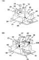
首先,参照图1和图2,对于本发明的实施例1涉及的搭载了光通信用棱镜的光收发模块的结构进行说明。图1是示出本发明的实施例1涉及的光收发模块的结构的概念图,图2是放大了与图1中示出的光收发模块的基板、作为构造体的台座、作为主要部的光通信用光学棱镜、发光元件、受光元件和光纤的结构相对的关系的剖面图的图。First, the configuration of an optical transceiver module equipped with a prism for optical communication according to Embodiment 1 of the present invention will be described with reference to FIGS. 1 and 2 . 1 is a conceptual diagram showing the structure of an optical transceiver module according to Embodiment 1 of the present invention, and FIG. 2 is an enlarged view of the substrate, the base as a structure, and the main part of the optical transceiver module shown in FIG. 1 . It is a cross-sectional view showing the relationship among the optical prisms, light-emitting elements, light-receiving elements, and optical fibers for optical communication.
图1中示出的光收发模块(以下记作光学模块)1是例如设置为光学线路终端装置(ONU)的一部分,在利用波分复用(WDM)传输方式进行双向通信时使用的模块。光学模块1安装在壳组件(キヤンパツケ一ジ)基座80上,利用罩81进行保护。在此,罩表示为透明体。此外,在壳组件基座80上设置多个连接销82,进行与光学模块1的发光元件、受光元件等光学元件电连接的电气元件(变压器、阻抗、放大器等)70与外部之间的电连接,但在图中省略了这些配线的表示。此外,在罩81上保持着被由氧化锆(ZrO2)等构成的光纤套管50保护的光纤51,光纤51与光学模块1的发光元件、受光元件等光学元件光学连接。光学模块1构成在基板41上。40是作为台座,形成为“コ”字型配置在基板41上。基板41和台座40由可使用蚀刻技术进行高精度加工的半导体材料、例如Si材料形成。基板41和台座40的上表面被用作安装发光部20、受光部10和光通信用光学棱镜30的基准面。An optical transceiver module (hereinafter referred to as an optical module) 1 shown in FIG. 1 is installed, for example, as part of an optical line terminal unit (ONU) and used for bidirectional communication using a wavelength division multiplexing (WDM) transmission method. The optical module 1 is mounted on a case assembly base 80 and is protected by a cover 81 . Here, the cover is represented as a transparent body. In addition, a plurality of connection pins 82 are provided on the case assembly base 80, and electrical components (transformers, impedances, amplifiers, etc.) connection, but the representation of these wirings is omitted in the figure. In addition, an
光通信用光学棱镜30由以各自的斜面隔着波长分离膜31相互对置的方式配置的直角棱镜30A和半球面透镜30B一体地构成。另外,在形成上述直角棱镜的直角的2个面上分别形成凸透镜33、34,并且,在两侧一体地形成安装用支承部32A、32B。将发光部20和光通信用光学棱镜30安装在台座40的上表面上,将发光部20配置在台座40的“コ”字的共通部上,将光通信用光学棱镜30配置在“コ”字的两翼部上。这时,将光通信用光学棱镜30的安装用支承部32A、32B设置在其下表面与台座40的上表面(图2中示出的点划线)一致的位置上,使得发光部20和光通信用光学棱镜30的光轴一致。此外,光通信用光学棱镜30具有在透射第一波长的光和第二波长的光的一方的同时、反射另一方的光谱。The
从发光部20发出的光经过粗的虚线示出的光路、即光通信用光学棱镜30的凸透镜33、直角棱镜30A、波长分离膜31和凸透镜34的光路被准直,射入到光纤51中。从光纤51发出的光经过粗的虚线示出的光路、即光通信用光学棱镜30的凸透镜34、直角棱镜30A、波长分离膜31、半球面透镜30B和凸透镜34的光路被准直,射入到基板10上设置的受光部10中。在此,发光部20具有例如激光二极管元件(LD元件),产生例如波长λ2=1.3μm的信号光L2。此外,受光部10具有例如光电二极管元件(PD元件),接收例如波长λ1=1.49μm的信号光L1。在发光部20的背面配置用于检验上述LD元件的输出的监视用PD60,将其设置在基板41上的支承部61上。The light emitted from the
图3A(A)-(D)是说明实施例1涉及的光通信用光学棱镜30的结构的图。3A(A)-(D) are diagrams illustrating the structure of the
图3A(A)是示出光通信用光学棱镜30的结构要素的斜视图。光通信用光学棱镜30具有直角棱镜30A和半球面透镜30B,该直角棱镜30A和半球面透镜30B配置成隔着光学膜之一的波长分离膜31各自的斜面相互对置。直角棱镜30A成为侧面是等腰直角三角形的三角柱状,隔着波长分离膜31直角棱镜30A和半球面透镜30B的相互的斜面相结合。该光通信用光学棱镜30具有波长选择性,进行不同波长的信号光(例如,具有上述波长λ1、λ2的信号光L1、L2)的分波和合波。具体地说,波长分离膜31例如原样透射波长λ1的信号光L1。另一方面,由于不透射波长λ2的信号光L2,因此,波长λ2的信号光L2被直角棱镜30A的斜面向与入射方向正交的方向反射。在形成直角棱镜30A的直角的2个面上,分别形成成为光学元件的凸透镜33、34。凸透镜33不限于球面透镜形状,也可以是非球面形状。或者,也可以是具有全息图形的菲涅耳波带板等的衍射光学元件。在球面透镜30B的斜面和直角棱镜30A的斜面粘结了的状态下,由于球面透镜30B的两侧端部作为光学系统无用,因此,进行切削以便成为与直角棱镜30A的侧面成为相同的面。在该两侧面上一体地形成安装用支承部32A、32B。这时,在如上所述地在台座40上安装了光通信用光学棱镜30时,在光通信用光学棱镜30与发光部20的光轴一致的位置上一体地形成安装用支承部32A、32B。在安装用支承部32A、32B上,如后所述地,设置用于与在台座40上进行安装时的引导标记进行定位的开口37、38。FIG. 3A(A) is a perspective view showing components of an
这样,由于光学模块1具有能检测作为接收光的信号光L1的受光部10、射出作为发送光的信号光L2的发光部20、在能选择性地反射和透射或者透射和反射信号光L1和信号光L2的基础上具有透镜功能并且具有安装用支承部的光通信用光学棱镜30,因此,形成比较紧凑的结构,并且能进行使用了一条光纤51的双向传输。In this way, since the optical module 1 has a
图3A(B)是在组合了光通信用光学棱镜30和安装用支承部32A、32B的状态下,从光的入射侧(凸透镜33侧)看的侧视图。3A(B) is a side view seen from the incident side of light (
图3A(C)是在组合了光通信用光学棱镜30和安装用支承部32A、32B的状态下,从背面看的侧视图。FIG. 3A(C) is a side view seen from the back in a state in which the
图3A(D)是在图3A(B)的D-D位置上向箭头方向看的剖面图。在光通信用光学棱镜30的遮挡下看见了安装用支承部32B的一部分。Fig. 3A(D) is a cross-sectional view viewed in the direction of the arrow at the position D-D of Fig. 3A(B). A part of the mounting
图3B(A)-(D)是说明取代用直角棱镜30A和半球棱镜30B的组合构成参照图3A(A)-(D)说明的实施例1涉及的光通信用光学棱镜30的结构,用直角棱镜30A和与其面对称的直角棱镜30A’的组合进行构成的实施例1的变形例的图。Fig. 3B (A)-(D) is to illustrate the structure of the
图3B(A)-(D)分别是与图3A(A)-(D)相对应的图。对比两者可知,只不过是取代半球棱镜30B使用直角棱镜30A’构成光通信用光学棱镜30的变更,因此,比较各图来看没有很大变化。但是,由于失去了半球棱镜30B所起的凸透镜的功能,因此,在形成直角棱镜30A’的直角的一个面上形成了成为光学元件的凸透镜34’。根据图3B(D)的剖面图可知,取代半球棱镜30B使用了直角棱镜30A’,而且形成了凸透镜34’。此外,在该例子中,由于使安装用支承部32A、32B与直角棱镜30A的宽度相同,因此,安装用支承部32B如虚线所示,成为隐藏在直角棱镜30A、30A’中的形式。在图3B(A)-(D)的实施例中,粘结了面对称的直角棱镜的斜面来使用,因此,如图3A(A)-(D)的实施例所示,不使用球面透镜30B。从而,不需要切削它的两侧端部的操作。3B(A)-(D) are diagrams corresponding to FIG. 3A(A)-(D), respectively. Comparing the two, it can be seen that the
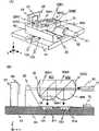
图4(A)、(B)是说明在基板41和台座40上安装作为光学元件的受光部10、发光部20和光通信用光学棱镜30的过程的斜视图。4(A) and (B) are perspective views illustrating the process of mounting the
在本发明中,如图4(A)所示,表示了示出在基板41和台座40的面上安装光学元件的安装位置的引导标记。91、92是安装设置在台座40的面上的发光部20的位置的标记。93、94是安装设置在台座40的面上的光通信用光学棱镜30的位置的标记。95、96是安装设置在基板41的面上的受光部10的位置的标记。这些标记能够在使用蚀刻技术高精度的加工基板41和台座40的过程中标注,因此能够正确地标注。In the present invention, as shown in FIG. 4(A), guide marks showing the mounting positions of the optical elements on the
图4(A)用虚线的箭头示出利用标记91、92引导,在台座40的面上安装发光部20,利用标记95、96引导,在基板41的面上安装受光部10。4(A) shows that the
图4(B)用箭头示出利用标记93、94引导安装光通信用光学棱镜30。在图中,标记93被光通信用光学棱镜30遮挡而看不见,但一边确认光通信用光学棱镜30的安装用支承部32A、32B的开口37、38与标记94、93的一致,一边在台座40的面上安装光通信用光学棱镜30。在此,设置了开口37、38,但也可以省略,使安装用支承部32A、32B的侧面与标记一致即可。再有,也可以取代基板41、台座40的面上设置的引导标记,将其形成为凸部,在光学元件侧设置与其嵌合的凹部,也可以是取代引导标记,开孔,在光学元件侧也开与其相对应的孔,用销将两者结合的形式。FIG. 4(B) shows that the
如上所述,在实施例1中,棱镜30A和半球面透镜30B中,在棱镜中形成直角的2个面分别形成凸透镜33、34,具有折射力。从而,形成简单的结构,并且能够一边利用凸透镜33使来自发光部20的信号光L2聚光,一边使其在接合面31中反射后,用凸透镜34聚光然后射入到光纤50的纤维51中。另一方面,能够在使从光纤51射出的信号光L1透射过接合面31后,利用半球面透镜30B的凸透镜进行聚光后,射入到受光部10中。As described above, in the first embodiment, the two surfaces forming a right angle in the
在此尽管并未说明,但在组合直角棱镜30A和半球面透镜30B时,能够如实施例2中说明地,利用使用凹凸的嵌合关系。即,在直角棱镜30A的斜面上形成凹部,在半球面透镜30B的斜面的与上述凹部相对应的位置上形成凸部,在组合时,装配成使得它们重合。这样,在装配的同时,相互的光轴就重合。因此,不需要粘结操作之外的使光轴重合的操作,能够实现低成本化。Although not described here, when the
(实施例2)(Example 2)
上述实施例1中的光通信用光学棱镜30是直接粘结了直角棱镜30A和波长分离膜31的斜面(连接面)、半球面透镜30B的斜面(连接面)和波长分离膜31的连接面的结构。因此,利用粘结剂例如紫外线硬化树脂覆盖连接面。在实施例2中,设定为在半球面透镜30B的斜面上设置波长分离膜31的膜厚以上深度的坑洼,在该坑洼中设置波长分离膜31的结构。The
图5(A)是用剖面示出了实施例2的光通信用光学棱镜30的结构要素的图。在直角棱镜30A的斜面30C上,在两端部形成着凹部35。在半球面透镜30B的实施例1中说明过的斜面30D(用虚线示出)的端部,在与斜面30C的凹部35相对应的位置上形成着凸部39。另一方面,在半球面透镜30B上,在从用虚线示出的位置退后的位置上形成着斜面30D’。31是在实施例1中说明过的波长分离膜,斜面30D’以该波长分离膜31的厚度,从虚线位置的斜面30D向后退。FIG. 5(A) is a cross-sectional view showing the constituent elements of the
图5(B)是示出在斜面30D’上粘结了波长分离膜31的状态的图。Fig. 5(B) is a diagram showing a state where the
图5(C)是示出接着图5(B),组合装配了直角棱镜30A和半球面透镜30B,使凹部35和凸部39一致地嵌合的状态的图。如图5FIG. 5(C) is a diagram showing a state in which the
(C)所示,在实施例2中,在粘结了直角棱镜30A和半球面透镜后,在直角棱镜30A的斜面30C与波长分离膜31之间形成气隙36。一般将波长分离膜31设置成能对于通过空气射入的光进行波长分离,从而,如实施例2所述,通过构成为形成气隙36的结构,就能够使用通用的波长分离膜。在此,波长分离膜31设置在半球面透镜30B的斜面侧,但在射入的光的方向相反的情况下,设置在直角棱镜30A的斜面侧也可。As shown in (C), in Example 2, after bonding the
再有,在图5(A)-(C)中,对于组合了图3A中说明的直角棱镜30A和半球面透镜30B的光通信用光学棱镜30进行了说明,但这关于组合了图3B中说明的直角棱镜30A和直角棱镜30A’的光通信用光学棱镜30也同样。Furthermore, in Fig. 5 (A)-(C), the
在本发明中,光通信用光学棱镜30是组合了直角棱镜30A和半球面透镜30B的装置。在一般的利用直角棱镜和半球面透镜的组合的光学棱镜中,进行光路调整不怎么困难。但是,在实施例1和实施例2中,由于在直角棱镜30A的光入射面上形成凸透镜33、34,因此在棱镜30A和半球面透镜30B的粘结时,必须要进行更严密的光轴调整。因此,作为两者的定位机构,通过利用凹凸关系并进行基于嵌合的定位,通过进行直角棱镜和半球面透镜的粘结操作,就能够自动地进行光轴调整。In the present invention, the
(实施例3)(Example 3)
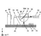
在上述实施例1和实施例2中,光学模块1一边利用凸透镜33使来自发光部20的信号光L2聚光,一边使其在直角棱镜30A的斜面(与半球面透镜30B的接合面)中反射后,射入到光纤51中。另一方面,在使从光纤51射出的信号光L1透射过直角棱镜30A的斜面(与半球面透镜30B的接合面)和波长分离膜31后,利用半球面透镜30B聚光并射入到受光部10中。对此,在实施例3中示出可以平面安装的结构。In the first and second embodiments described above, the optical module 1 condenses the signal light L2 from the
图6是用与实施例1的图2相对应的剖面示出实施例3的结构的图。来自发光部20的信号光L2如粗虚线所示地被凸透镜33聚光,透射过直角棱镜30A的斜面(与半球面透镜30B的接合面)和波长分离膜31,被半球面透镜30B聚光后,射入到光纤51中。另一方面,从光纤51射出的信号光L1如粗虚线所示地被半球面透镜30B聚光,在直角棱镜30A的斜面(与半球面透镜30B的接合面)和波长分离膜31中被反射,再次被半球面透镜30B聚光后,射入到受光部10中。这样就能进行平面安装。再有,在实施例4中不需要实施例1和2中必需的凸透镜34。FIG. 6 is a view showing the structure of Example 3 in a section corresponding to FIG. 2 of Example 1. FIG. The signal light L2 from the
(实施例4)(Example 4)
图7是用与实施例3的图6相对应的剖面示出实施例4的结构的图。实施例4本质上与上述实施例3相同。来自发光部20的信号光L2以与实施例3的图6相同的形式射入到光纤51中。另一方面,从光纤51射出的信号光L1被半球面透镜30B聚光,在棱镜30A’的斜面(与半球面透镜30B的接合面)和波长分离膜31中反射,再次被半球面透镜30B聚光后射入到受光部10中。这样就能进行平面安装。FIG. 7 is a diagram showing the structure of Embodiment 4 in a cross section corresponding to FIG. 6 of Embodiment 3. FIG. Embodiment 4 is essentially the same as Embodiment 3 above. The signal light L2 from the
与实施例3比较而言,与实施例3使用了侧面是等腰直角三角形的三角柱状的直角棱镜30A相对,在实施例4中,为作为不等边直角三角形的三角柱状的直角棱镜30A’,在棱镜30A’的斜面(与半球面透镜30B的接合面)中,使其相对信号光L1的前进方向以大于45度的角度进行反射。一般地,角度越大,波长分离膜31的设计和制造就越简单。从而,在实施例4中,能够使用设计简单、制造成本廉价的波长分离膜31。Compared with Example 3, in contrast to Example 3 using a triangular prism-shaped
(实施例5)(Example 5)
图8是用与实施例3的图6相对应的剖面示出实施例5的结构的图。对比图8和图6可知,在实施例5中,将受光部10保持在基板41的坑洼部41’中。在此,除设置在光通信用光学棱镜30的直角棱镜30A和半球面透镜30B的斜面(连接面)上的波长分离膜31之外,还用波长分离膜31’覆盖了保持在基板41的坑洼部41’中的受光部10的上表面。从而,光通信用光学棱镜30就如图中的粗虚线所示地,与来自发光部20的信号光L2和从光纤51射出的信号光L1的波长相对应地控制传输方向。由于利用波长分离膜31和波长分离膜31’这两者进行受光部10应该接收的波长的光的选择,因此,能够更有效地抑制信号光L1、L2的串扰。FIG. 8 is a view showing the structure of Embodiment 5 in a cross section corresponding to FIG. 6 of Embodiment 3. FIG. Comparing Fig. 8 and Fig. 6, it can be seen that in the fifth embodiment, the
(实施例6)(Example 6)
与实施例1~实施例5中为应对利用2个波长进行收发的结构相对,实施例6是应对利用3个波长的收发的结构的例子。图9(A)、Embodiment 6 is an example of a configuration that supports transmission and reception using three wavelengths, as opposed to the configuration that supports transmission and reception using two wavelengths in Embodiments 1 to 5. Figure 9(A),
(B)是以与实施例1的图1的光学模块的结构的概念图相对应的概念图和与实施例3的图6相对应的剖面示出实施例6的结构的图。(B) is a diagram showing the configuration of Embodiment 6 in a conceptual diagram corresponding to the conceptual diagram of the configuration of the optical module in FIG. 1 of Embodiment 1 and a cross-section corresponding to FIG. 6 of Embodiment 3.
对比图9(A)和图1可知,实施例6的光学模块成为省略了壳组件基座80和罩81来表示的斜视图。由于实施例6进行平面安装,因此成为将被光纤套管50保护的光纤51保持在光学模块的横向位置上的结构。此外,与接收的光信号是2个相对应,是两个光通信用光学棱镜301、302,并且为直接连结配置。另外,与接收的光信号是2个相对应,受光部也是101、102两个,与光通信用光学棱镜301、302相对应地配置在基板41上。Comparing FIG. 9(A) with FIG. 1, it can be seen that the optical module of the sixth embodiment is a perspective view in which the case assembly base 80 and the cover 81 are omitted. Since the embodiment 6 is planarly mounted, the
图9(B)是放大示出了与实施例6的光收发模块的基板、作为构造体的台座、作为主要部分的光通信用光学棱镜、发光元件、受光元件和光纤的结构相对关系的剖面图。在直接连结的光通信用光学棱镜301、302的内部,前段的光通信用光学棱镜301为参照图3B说明的直角棱镜30A1和30A1’以对接各自的斜面的形式粘结而构成的光通信用光学棱镜,并且,在与发光部20相对置的面上粘结了凸透镜33、在与受光部101相对置的面上粘结了凸透镜34。另一方面,后段的光通信用光学棱镜302为与实施例5之前说明过的直角棱镜和半球面透镜以对接了各自的斜面的形式粘结的结构的光通信用光学棱镜30相同的结构。在后段的光通信用光学棱镜302的与半球面透镜30B相对置的面上,在基板41上设置受光部102。除在成为各个光通信用光学棱镜301、302的粘结面的斜面上,设置使不同波长的光透射的波长分离膜31、31’之外,还在各个受光部101、102的光的入射面之前设置了使不同波长的光透射的波长分离膜311、312。此外,光通信用光学棱镜301、302具有在透射波长不同的三个光中的一个光的同时、反射另外两个光的光谱。再有,在该实施例中,也可以如图3B中说明地,将后段的光通信用光学棱镜302的半球面透镜30B改变为直角棱镜。9(B) is an enlarged cross-sectional view showing the relationship between the substrate of the optical transceiver module of the sixth embodiment, the base as the structure, the optical prism for optical communication as the main part, the light-emitting element, the light-receiving element, and the optical fiber. picture. Inside the directly connected
在光通信用光学棱镜301和302的每一个中,在两侧一体地形成安装用支承部32A1、32B1和32A2、32B2。这些安装用支承部也可以形成为与光通信用光学棱镜301、302共通的部件。In each of the
实施例6的光学模块应对利用3个波长的收发。利用前段的光通信用光学棱镜301的凸透镜33对来自发光部20的信号光L2进行聚光,使其透射过2个直角棱镜30A1、30A2的接合面的波长分离膜31、和后段的光通信用光学棱镜302的直角棱镜30A2与半球面透镜30B的接合面的波长分离膜31’,利用半球面透镜30B聚光后射入到光纤51中。另一方面,利用半球面透镜30B对从光纤51射出的2个波长的信号光L1和信号光L3进行聚光,导入到后段的光通信用光学棱镜302中。使导入的信号光L1在后段的光通信用光学棱镜302的直角棱镜30A2与半球面透镜30B的接合面被反射,利用半球面透镜30B聚光,透射过波长分离膜312并射入到受光部102中。使导入的信号光L3透射过后段的光通信用光学棱镜302的接合面,在前段的光通信用光学棱镜301的直角棱镜30A1与30A1’的接合面中反射,利用凸透镜34聚光,并透射波长分离膜301、射入到受光部101中。The optical module of the sixth embodiment supports transmission and reception using three wavelengths. The signal light L2 from the
再有,在参照图9(A)、(B)说明的应对利用3个波长的收发的光收发模块的结构中,也可以使光通信用光学棱镜302成为参照图3B说明的直角棱镜的组合。该情况下,在从光纤射入的光的入射面上也具有凸透镜。另外,在进行多波长的光信号的收发的系统中,尽管发光部20产生一个波长的光,但当然接收多个波长的光。Furthermore, in the structure of the optical transceiver module dealing with transmission and reception utilizing three wavelengths described with reference to FIG. . In this case, a convex lens is also provided on the incident surface of light entering from the optical fiber. In addition, in a system that transmits and receives optical signals of multiple wavelengths, although the
此外,在上述的实施例中,基板41和台座40都为分开制作然后组合,但它们也可以一体地形成。Furthermore, in the above-described embodiments, both the
以上,关于本发明涉及的光通信用光学棱镜和光收发模块的优选实施例进行了几点说明,但本发明不限定于上述实施例。As mentioned above, several points of preferred embodiments of the optical prism for optical communication and the optical transceiver module according to the present invention have been described, but the present invention is not limited to the above embodiments.
另外,用以下的结构能够实现本发明。In addition, the present invention can be realized with the following structures.
1.一种光收发模块,由下述部件构成:基板;配置在上述基板上的コ字形的台座;配置在上述台座的コ字形的共通部的面上的发光部;配置在上述基板上的两个受光部;第1光通信用光学棱镜;以及第2光通信用光学棱镜,其中,该第1光通信用光学棱镜是直角棱镜的斜面和与上述直角棱镜的斜面面对称的直角棱镜的斜面隔着波长分离膜、各斜面相互对置配置而一体化的光通信用复合光学棱镜,该光通信用复合光学棱镜构成为在上述斜面的位置具有波长选择膜,并且形成上述2个直角棱镜的直角的2个面中的光入射面和光射出面具有透镜功能,并且,在上述光通信用复合光学棱镜的两侧具有安装用支承部,所述安装用支承部在与向上述光通信用复合光学棱镜射入的光和从上述光通信用复合光学棱镜射出的光的光路正交的方向上延伸,该第二光通信用光学棱镜与上述第一光通信用光学棱镜级联配置,是直角棱镜的斜面和半球面透镜的斜面隔着波长分离膜、各斜面相互对置配置而一体化的光通信用复合光学棱镜,该光通信用复合光学棱镜构成为在上述斜面的位置具有波长选择膜,并且形成上述直角棱镜的直角的2个面的光入射面和光射出面具有透镜功能,并且,在上述光通信用复合光学棱镜的两侧具有安装用支承部,所述安装用支承部在与向上述光通信用复合光学棱镜射入的光和从上述光通信用复合光学棱镜射出的光的光路正交的方向上延伸,上述光通信用复合光学棱镜的上述安装用支承部被支承在上述台座的コ字形的两翼部的上表面,使得上述光通信用复合光学棱镜位于从上述发光部发出的光射入到上述第1光通信用复合光学棱镜中、并且从上述第1、第2光通信用复合光学棱镜射出的光射入到上述2个受光部的每一个的位置。1. An optical transceiver module, comprising the following components: a substrate; a U-shaped pedestal disposed on the above-mentioned substrate; a light-emitting portion disposed on the surface of the U-shaped common portion of the above-mentioned pedestal; Two light-receiving parts; the 1st optical communication optical prism; and the 2nd optical communication optical prism, wherein, the 1st optical communication optical prism is a right-angled prism symmetrical to the inclined plane of the right-angled prism and the inclined plane of the above-mentioned right-angled prism A composite optical prism for optical communication in which the oblique surfaces of the optical communication are arranged to face each other and integrated with a wavelength separation film interposed therebetween. The light incident surface and the light exit surface of the two right-angled surfaces of the prism have a lens function, and there are support parts for installation on both sides of the above-mentioned compound optical prism for optical communication, and the support parts for the installation are connected to the above-mentioned optical communication. Extending in a direction perpendicular to the light path of the light incident through the composite optical prism and the light emitted from the above-mentioned composite optical prism for optical communication, the second optical prism for optical communication is arranged in cascade with the above-mentioned first optical prism for optical communication, It is a composite optical prism for optical communication in which the oblique surfaces of a rectangular prism and the oblique surfaces of a hemispherical lens are arranged to face each other via a wavelength separation film and are integrated. The composite optical prism for optical communication is configured to have wavelength A selective film, and the light incident surface and the light exit surface of the two surfaces forming the right angle of the above-mentioned rectangular prism have a lens function, and there are mounting support parts on both sides of the above-mentioned compound optical prism for optical communication, and the mounting support parts Extending in a direction perpendicular to the optical path of light incident to the above-mentioned compound optical prism for optical communication and light emitted from the compound optical prism for optical communication, the above-mentioned mounting support portion of the compound optical prism for optical communication is supported On the upper surface of the U-shaped two wing parts of the above-mentioned pedestal, the above-mentioned compound optical prism for optical communication is positioned so that the light emitted from the above-mentioned light emitting part enters the above-mentioned first compound optical prism for optical communication, and the light from the above-mentioned first, second The light emitted from the compound optical prism for 2 optical communication is incident on each position of the above-mentioned 2 light receiving parts.
2.上述1中记载的光收发模块,构成上述光通信用复合光学棱镜的上述2个直角棱镜和上述直角棱镜及上述半球面透镜在各自的上述斜面上具有定位装置,所述定位装置用于规定上述2个直角棱镜以及上述直角棱镜和上述半球面透镜的相对位置。2. The optical transceiver module described in the above-mentioned 1, the above-mentioned two right-angle prisms, the above-mentioned right-angle prism and the above-mentioned hemispherical lens that constitute the above-mentioned compound optical prism for optical communication have a positioning device on each of the above-mentioned slopes, and the positioning device is used for The relative positions of the two rectangular prisms and the rectangular prism and the hemispherical lens are specified.
3.上述1中记载的光收发模块,在上述光通信用复合光学棱镜的上述2个直角棱镜以及上述直角棱镜和半球面透镜的相对置的斜面的某一方与上述波长分离膜之间形成有空隙。3. The optical transceiver module described in 1 above, wherein the above-mentioned two right-angle prisms of the above-mentioned compound optical prism for optical communication and one of the opposite inclined surfaces of the above-mentioned right-angle prism and hemispherical lens are formed between the above-mentioned wavelength separation film. void.
4.上述1中记载的光收发模块,具有:用于配置被安装在上述台座的コ字形的共通部的面上的发光部的引导标记;用于配置被安装在上述基板上的受光部的引导标记;以及用于配置被安装在上述台座的两翼部的上表面的上述安装用支承部的引导标记。4. The optical transceiver module described in the above 1, which has: a guide mark for disposing the light emitting part mounted on the surface of the U-shaped common part of the above-mentioned pedestal; a guide mark for disposing the light receiving part mounted on the above-mentioned substrate a guide mark; and a guide mark for arranging the above-mentioned mounting support portion attached to the upper surface of both wing portions of the above-mentioned pedestal.
5.上述1中记载的光收发模块,在上述2个直角棱镜以及直角棱镜的斜面与半球面透镜的斜面相互对置的斜面上具有上述波长分离膜,并且,在上述基板上设置的2个受光部的光的射入侧的光路上也配置着波长分离膜。5. The optical transceiver module described in 1 above, which has the above-mentioned wavelength separation film on the above-mentioned two right-angle prisms and the slope on which the slope of the right-angle prism and the slope of the hemispherical lens are opposed to each other, and two of the above-mentioned substrates are provided A wavelength separation film is also disposed on the optical path on the light incident side of the light receiving unit.
6.上述1中记载的光收发模块,将第2光通信用复合光学棱镜的上述半球面透镜置换为与上述直角棱镜的斜面面对称的直角棱镜。6. The optical transceiver module described in 1 above, wherein the hemispherical lens of the second compound optical prism for optical communication is replaced by a right-angle prism symmetrical to the oblique plane of the above-mentioned right-angle prism.
7.上述1中记载的光收发模块,上述基板和上述台座一体地形成。7. The optical transceiver module described in 1 above, wherein the substrate and the base are integrally formed.
8.上述3中记载的光收发模块,上述光通信用复合光学棱镜的安装用支承部被标注有安装用标记,所述安装用标记与上述台座上标注的标记相对应。8. The optical transceiver module described in 3 above, wherein the mounting support portion of the composite optical prism for optical communication is marked with mounting marks corresponding to the marks marked on the base.
Claims (20)
Applications Claiming Priority (2)
| Application Number | Priority Date | Filing Date | Title |
|---|---|---|---|
| JP357689/2005 | 2005-12-12 | ||
| JP2005357689AJP4759380B2 (en) | 2005-12-12 | 2005-12-12 | Optical prism for optical communication and optical transceiver module |
Publications (2)
| Publication Number | Publication Date |
|---|---|
| CN1983880A CN1983880A (en) | 2007-06-20 |
| CN1983880Btrue CN1983880B (en) | 2010-11-10 |
Family
ID=38166159
Family Applications (1)
| Application Number | Title | Priority Date | Filing Date |
|---|---|---|---|
| CN200610160311XAExpired - Fee RelatedCN1983880B (en) | 2005-12-12 | 2006-11-21 | Optical prism and optical transceiver module for optical communications |
Country Status (3)
| Country | Link |
|---|---|
| US (1) | US7991290B2 (en) |
| JP (1) | JP4759380B2 (en) |
| CN (1) | CN1983880B (en) |
Cited By (1)
| Publication number | Priority date | Publication date | Assignee | Title |
|---|---|---|---|---|
| CN102854582A (en)* | 2011-08-31 | 2013-01-02 | 索尔思光电(成都)有限公司 | Optical transmitting assembly, optical transceiver and manufacturing and applying method |
Families Citing this family (35)
| Publication number | Priority date | Publication date | Assignee | Title |
|---|---|---|---|---|
| JP2008181025A (en)* | 2007-01-25 | 2008-08-07 | Sumitomo Electric Ind Ltd | Single fiber bidirectional optical module |
| JP4894692B2 (en)* | 2007-09-21 | 2012-03-14 | 住友電気工業株式会社 | Optical transceiver module |
| JP4983703B2 (en)* | 2008-04-08 | 2012-07-25 | 日立電線株式会社 | Optical transmission system |
| US8121484B2 (en)* | 2008-04-28 | 2012-02-21 | Sumitomo Electric Industries, Ltd. | Bi-direction optical module installing light-emitting device and light-receiving device in signal package |
| JP5315983B2 (en)* | 2008-12-25 | 2013-10-16 | 三菱電機株式会社 | Optical module and wavelength control method |
| JP2010164818A (en)* | 2009-01-16 | 2010-07-29 | Sumitomo Electric Ind Ltd | Single core bidirectional optical module |
| JP2011066402A (en)* | 2009-08-20 | 2011-03-31 | Sumitomo Electric Ind Ltd | Optical transmitter module and method of manufacturing the same |
| JP2011044635A (en)* | 2009-08-24 | 2011-03-03 | Alps Electric Co Ltd | Optical communication module |
| KR101041570B1 (en)* | 2009-08-24 | 2011-06-15 | 한국전자통신연구원 | Optical communication module |
| JP5562659B2 (en)* | 2010-01-21 | 2014-07-30 | オリンパス株式会社 | Mounting apparatus and mounting method |
| KR101419381B1 (en)* | 2010-04-07 | 2014-07-15 | 한국전자통신연구원 | Apparatus for Bi-directional Optical transmission |
| KR101176950B1 (en)* | 2010-09-17 | 2012-08-30 | 주식회사 유나이브 | Optical transmitter, optical receiver for passive alignment of parts and method for passive alignment of parts |
| JP2012083166A (en)* | 2010-10-08 | 2012-04-26 | Hamamatsu Photonics Kk | Total reflection spectroscopic measurement apparatus |
| JP5550521B2 (en)* | 2010-10-20 | 2014-07-16 | 浜松ホトニクス株式会社 | Total reflection spectrometer |
| US8666254B2 (en)* | 2011-04-26 | 2014-03-04 | The Boeing Company | System and method of wireless optical communication |
| US9195015B2 (en) | 2011-06-29 | 2015-11-24 | Source Photonics, Inc. | Bi-directional fiber optic transceivers, housings therefor, and methods for making and using the same |
| CN102213807A (en)* | 2011-06-29 | 2011-10-12 | 索尔思光电(成都)有限公司 | Single-fiber bidirectional transceiver module and capsulation thereof |
| TWI578051B (en)* | 2013-03-07 | 2017-04-11 | 鴻海精密工業股份有限公司 | Optical connector |
| CN102707410A (en)* | 2012-06-25 | 2012-10-03 | 张家港市光学仪器有限公司 | Clamp for gluing pentagonal prism |
| KR101721851B1 (en)* | 2012-08-30 | 2017-03-31 | 한국전자통신연구원 | Bi-directional optical module |
| CN205067323U (en)* | 2013-01-22 | 2016-03-02 | 贝克顿·迪金森公司 | Optical system , optical coupler and optical sensor |
| US9429725B2 (en)* | 2013-04-19 | 2016-08-30 | Avago Technologies General Ip (Singapore) Pte. Ltd. | Bidirectional parallel optical transceiver module and a method for bidirectionally communicating optical signals over an optical link |
| TW201504703A (en)* | 2013-07-25 | 2015-02-01 | Hon Hai Prec Ind Co Ltd | Optical coupling module, photoelectric conversion device and optical fiber coupling connector |
| WO2015112284A2 (en)* | 2013-12-17 | 2015-07-30 | Picometrix, Llc | System for transmitting and receiving electromagnetic radiation |
| US9470857B2 (en)* | 2014-06-13 | 2016-10-18 | Sumitomo Electric Industries, Ltd. | Optical module with beam splitter on reflecting surface |
| TWM507618U (en)* | 2014-07-04 | 2015-08-21 | Ezconn Corp | OPTO-electronic micro-module |
| WO2016143395A1 (en) | 2015-03-11 | 2016-09-15 | ナルックス株式会社 | Component equipped with position measuring part and measuring method |
| JP2016178218A (en)* | 2015-03-20 | 2016-10-06 | 日本オクラロ株式会社 | Optical transmission module |
| JP6051253B2 (en)* | 2015-03-30 | 2016-12-27 | 沖電気工業株式会社 | Optical two-way communication module |
| US10067320B2 (en) | 2015-11-10 | 2018-09-04 | Himax Technologies Limited | Lens module |
| KR101843469B1 (en)* | 2016-04-19 | 2018-03-30 | 옵티시스 주식회사 | Optical connector |
| US11543353B2 (en)* | 2019-01-18 | 2023-01-03 | Essenlix Corporation | Multi-mode illumination system |
| JP7121289B2 (en)* | 2019-02-05 | 2022-08-18 | 日本電信電話株式会社 | Wavelength selective optical receiver |
| CN115166911A (en)* | 2021-04-01 | 2022-10-11 | 讯芸电子科技(中山)有限公司 | Transistor outline package optical transceiver |
| CN113960744B (en)* | 2021-11-05 | 2023-09-12 | 中国工程物理研究院机械制造工艺研究所 | Clamp for clamping wedge-shaped mirror, wedge-shaped mirror and optical device |
Citations (1)
| Publication number | Priority date | Publication date | Assignee | Title |
|---|---|---|---|---|
| CN1123417A (en)* | 1993-11-18 | 1996-05-29 | 富士通株式会社 | Optical module for two-way transmission |
Family Cites Families (17)
| Publication number | Priority date | Publication date | Assignee | Title |
|---|---|---|---|---|
| JP2683618B2 (en)* | 1987-07-24 | 1997-12-03 | 並木精密宝石株式会社 | Polarizing prism |
| JPH03186805A (en)* | 1989-12-15 | 1991-08-14 | Shimadzu Corp | Polarizing prism |
| DE4029327A1 (en)* | 1990-09-15 | 1992-03-19 | Bayer Ag | POLYAMIDE MEASURES FOR PACKAGING MATERIALS AND THEIR USE |
| US5526168A (en)* | 1991-09-18 | 1996-06-11 | Linotype-Hell Ag | Light beam deflection means |
| JP2002208161A (en)* | 1993-02-05 | 2002-07-26 | Ricoh Co Ltd | Optical pickup device |
| JP3645684B2 (en)* | 1997-03-28 | 2005-05-11 | オリンパス株式会社 | Optical prism |
| JP3698393B2 (en) | 1998-12-11 | 2005-09-21 | 富士通株式会社 | Structure of optical transceiver module and manufacturing method thereof |
| JP2001318340A (en)* | 2000-05-10 | 2001-11-16 | Nikon Corp | Optical path synthesis optical system |
| JP2003066531A (en)* | 2001-05-21 | 2003-03-05 | Hitachi Ltd | Projection display device |
| JP2003014987A (en)* | 2001-06-28 | 2003-01-15 | Kyocera Corp | Optical path conversion body, its mounting structure, and optical module |
| JP2003075766A (en)* | 2001-09-04 | 2003-03-12 | Olympus Optical Co Ltd | Optical filter device |
| JP4250896B2 (en)* | 2002-02-19 | 2009-04-08 | 株式会社日立製作所 | Projection device and projection-type image display device using the same |
| JP4393094B2 (en)* | 2003-04-10 | 2010-01-06 | キヤノン株式会社 | Optical system |
| JP2005043635A (en)* | 2003-07-28 | 2005-02-17 | Fujinon Corp | Optical prism for optical communication, optical transmitting/receiving module, and optical prism |
| JP4433730B2 (en) | 2003-09-05 | 2010-03-17 | 住友電気工業株式会社 | Optical filter holding member and optical transmission / reception module |
| JP3781026B2 (en)* | 2003-09-25 | 2006-05-31 | 住友電気工業株式会社 | Optical module, optical transceiver and optical joint sleeve |
| JP2005321509A (en)* | 2004-05-07 | 2005-11-17 | Olympus Corp | Optical element |
- 2005
- 2005-12-12JPJP2005357689Apatent/JP4759380B2/ennot_activeExpired - Fee Related
- 2006
- 2006-11-21CNCN200610160311XApatent/CN1983880B/ennot_activeExpired - Fee Related
- 2006-11-21USUS11/602,356patent/US7991290B2/ennot_activeExpired - Fee Related
Patent Citations (1)
| Publication number | Priority date | Publication date | Assignee | Title |
|---|---|---|---|---|
| CN1123417A (en)* | 1993-11-18 | 1996-05-29 | 富士通株式会社 | Optical module for two-way transmission |
Non-Patent Citations (4)
| Title |
|---|
| JP昭60-60604A 1985.04.08 |
| JP特开2005-202082A 2005.07.28 |
| JP特开2005-43635A 2005.02.17 |
| JP特开平9-318853A 1997.12.12 |
Cited By (2)
| Publication number | Priority date | Publication date | Assignee | Title |
|---|---|---|---|---|
| CN102854582A (en)* | 2011-08-31 | 2013-01-02 | 索尔思光电(成都)有限公司 | Optical transmitting assembly, optical transceiver and manufacturing and applying method |
| CN102854582B (en)* | 2011-08-31 | 2015-01-14 | 索尔思光电(成都)有限公司 | Optical transmitting assembly, optical transceiver and manufacturing and applying method |
Also Published As
| Publication number | Publication date |
|---|---|
| JP2007163666A (en) | 2007-06-28 |
| JP4759380B2 (en) | 2011-08-31 |
| US7991290B2 (en) | 2011-08-02 |
| CN1983880A (en) | 2007-06-20 |
| US20070146881A1 (en) | 2007-06-28 |
Similar Documents
| Publication | Publication Date | Title |
|---|---|---|
| CN1983880B (en) | Optical prism and optical transceiver module for optical communications | |
| US8380075B2 (en) | Optical transceiver module | |
| CN101458370B (en) | Optical module | |
| TWI286617B (en) | Small form factor all-polymer optical device with integrated dual beam path based on total internal reflection optical turn | |
| CN1328604C (en) | 3-D optical ware guide and its producing method, optical module and optical transmission system | |
| TWI511477B (en) | Optical transceiver | |
| TWI298398B (en) | Photo module | |
| CN101918872A (en) | Optical Transceiver Module | |
| JP2005234052A (en) | Optical transmission and reception module | |
| JP2010122312A (en) | Transmission/reception lens block and optical module using the same | |
| JP4977594B2 (en) | Single-core bidirectional optical communication module | |
| US20030223701A1 (en) | Ferrule part and optical communications module | |
| US20060013541A1 (en) | Optoelectronic module | |
| US20050084217A1 (en) | Optical module capable of transmitting optical signal in bi-directional with single fiber | |
| US6775441B2 (en) | Optical waveguide connecting structure, optical element mounting structure and optical fiber mounting structure | |
| JP2003279808A (en) | Optical transmission/reception module | |
| JPH09211267A (en) | Optical semiconductor module | |
| KR102252682B1 (en) | Multi-channel optical module device and manufacturing method thereof | |
| JP2005010309A (en) | Optical transmitting/receiving device and optical fiber | |
| TWI259297B (en) | Fiber waveguide optical subassembly module | |
| JP2008020720A (en) | Optical waveguide and parallel optical transmitter-receiver | |
| JP2005134803A (en) | Ferrule with optical isolator and optical transmission/reception module equipped with the same | |
| JP2897742B2 (en) | Optical transceiver module | |
| JPH08254636A (en) | Optical transceiver module | |
| US20250314840A1 (en) | Optical waveguide component |
Legal Events
| Date | Code | Title | Description |
|---|---|---|---|
| C06 | Publication | ||
| PB01 | Publication | ||
| C10 | Entry into substantive examination | ||
| SE01 | Entry into force of request for substantive examination | ||
| ASS | Succession or assignment of patent right | Owner name:HITACHI CO., LTD. Free format text:FORMER OWNER: HITACHI COMMUNICATION TECHNOLOGIES LTD. Effective date:20100318 | |
| C41 | Transfer of patent application or patent right or utility model | ||
| TA01 | Transfer of patent application right | Effective date of registration:20100318 Address after:Tokyo, Japan, Japan Applicant after:Hitachi Ltd. Address before:Tokyo, Japan, Japan Applicant before:Hitachi Communications Technology Co., Ltd. | |
| C14 | Grant of patent or utility model | ||
| GR01 | Patent grant | ||
| CF01 | Termination of patent right due to non-payment of annual fee | ||
| CF01 | Termination of patent right due to non-payment of annual fee | Granted publication date:20101110 Termination date:20161121 |