CN1982107B - Independently opening doors for an automotive door opening - Google Patents
Independently opening doors for an automotive door openingDownload PDFInfo
- Publication number
- CN1982107B CN1982107BCN2006100903009ACN200610090300ACN1982107BCN 1982107 BCN1982107 BCN 1982107BCN 2006100903009 ACN2006100903009 ACN 2006100903009ACN 200610090300 ACN200610090300 ACN 200610090300ACN 1982107 BCN1982107 BCN 1982107B
- Authority
- CN
- China
- Prior art keywords
- door
- car
- vehicle
- link
- closed position
- Prior art date
- Legal status (The legal status is an assumption and is not a legal conclusion. Google has not performed a legal analysis and makes no representation as to the accuracy of the status listed.)
- Expired - Fee Related
Links
- 230000007246mechanismEffects0.000claimsdescription41
- 230000007935neutral effectEffects0.000claimsdescription9
- 230000008878couplingEffects0.000claims1
- 238000010168coupling processMethods0.000claims1
- 238000005859coupling reactionMethods0.000claims1
- 238000007789sealingMethods0.000description4
- 230000005540biological transmissionEffects0.000description2
- 230000008602contractionEffects0.000description2
- 238000010586diagramMethods0.000description2
- 206010017577Gait disturbanceDiseases0.000description1
- 230000009286beneficial effectEffects0.000description1
- 238000010276constructionMethods0.000description1
- 230000013011matingEffects0.000description1
- 238000000034methodMethods0.000description1
- 238000005728strengtheningMethods0.000description1
Images


Classifications
- B—PERFORMING OPERATIONS; TRANSPORTING
- B60—VEHICLES IN GENERAL
- B60J—WINDOWS, WINDSCREENS, NON-FIXED ROOFS, DOORS, OR SIMILAR DEVICES FOR VEHICLES; REMOVABLE EXTERNAL PROTECTIVE COVERINGS SPECIALLY ADAPTED FOR VEHICLES
- B60J5/00—Doors
- B60J5/04—Doors arranged at the vehicle sides
- B60J5/047—Doors arranged at the vehicle sides characterised by the opening or closing movement
- B60J5/0477—Doors arranged at the vehicle sides characterised by the opening or closing movement with two doors opening in opposite direction
- B60J5/0479—Doors arranged at the vehicle sides characterised by the opening or closing movement with two doors opening in opposite direction without B-pillar or releasable B-pillar, i.e. the pillar is moving with door
Landscapes
- Engineering & Computer Science (AREA)
- Mechanical Engineering (AREA)
- Body Structure For Vehicles (AREA)
- Lock And Its Accessories (AREA)
Abstract
Translated fromChinese
Description
Translated fromChinese技术领域technical field
本发明涉及车辆车门系统,更具体地说,涉及无中柱车门口所用的车门系统。This invention relates to vehicle door systems and, more particularly, to vehicle door systems for pillarless vehicle doorways.
背景技术Background technique
汽车车身的同一侧经常设有多个车门。通常在汽车车身同一侧的一对相邻车门都是相对汽车面向后打开。这些面向后的相邻车门一般都各自安装在一个连接柱上。所以,各车门都设有相应的车门口。There are often multiple doors on the same side of an automobile body. Usually a pair of adjacent doors on the same side of the vehicle body open rearwardly relative to the vehicle. These rearwardly facing adjacent doors are typically each mounted on a connecting post. Therefore, each vehicle door is provided with a corresponding vehicle door.
现有技术中,相邻的车门口已被合并成一个共用的车门口。像这样的车门口都被设计成无中柱车门口,并已在具有一排以上座椅的货车或运动型多功能车中使用。无中柱车门口在前排和后排座椅之间没有安装中柱。为了提供对车身的侧面支撑,前后车门一般都相互扣在一起,共同提供侧面的结构支撑。因为前后车门都与车身枢接,所以对于这样的车门,用户通常必须先打开前车门,然后才能打开或关闭后车门。In the prior art, adjacent vehicle doorways have been merged into one shared vehicle doorway. Doorways like these are designed as pillarless doorways and are already used in vans or sport utility vehicles with more than one row of seats. Pillarless doorways do not have a center pillar installed between the front and rear seats. In order to provide side support for the vehicle body, the front and rear doors are usually buckled together to provide side structural support. Because the front and rear doors are pivotally connected to the vehicle body, with such doors, the user typically must first open the front doors before opening or closing the rear doors.
发明内容Contents of the invention
在本发明的一个实施例中,汽车设有供乘客进出的无中柱车身口。第一车门具有第一端,它围绕一轴线枢接在汽车的靠近车身口周边的位置。第一车门的第二端在关闭位置时延伸至车身口的中心区,在敞开位置时向离开车身口的方向延伸。第二车门具有第一端,它可平移地连接在汽车的靠近车身口周边的位置,并且与第一车门的第一端隔开。第二车门的第二端在第二车门处于关闭位置时也是可平移地连接在汽车的靠近车身口中心区的位置。当第一车门与第二车门都在关闭位置时,两个车门相互配合将车身口关闭。第一车门关闭时,第二车门可以相对汽车沿着固定的平移路径平移,使第二车门的两端离开汽车平移到中间位置,与第一车门隔开一间隙。第二车门的其中一端可以与汽车分离,使第二车门相对汽车从中间位置转动到敞开位置。本实施例是提出了权利要求的本发明的非限制性实例。In one embodiment of the invention, the automobile is provided with a pillarless body opening for passenger entry and exit. The first door has a first end pivotally connected to a position of the vehicle near the periphery of the body opening about an axis. The second end of the first door extends to the central area of the body opening when in the closed position, and extends away from the body opening when in the open position. The second door has a first end translatably attached to the vehicle at a location adjacent the perimeter of the body opening and spaced from the first end of the first door. The second end of the second door is also translationally connected to the central area of the vehicle body opening when the second door is in the closed position. When both the first car door and the second car door are in the closed position, the two car doors cooperate with each other to close the body opening. When the first car door is closed, the second car door can be translated relative to the car along a fixed translation path, so that both ends of the second car door can move away from the car to a middle position, and there is a gap between the second car door and the first car door. One end of the second door can be separated from the vehicle so that the second door can be rotated from a neutral position to an open position relative to the vehicle. This embodiment is a non-limiting example of the claimed invention.
在本发明的另一个实施例中,汽车在其车身的一侧设有一对将无中柱车门口关闭的向外对开的门。该汽车具有铰接在汽车的靠近无中柱车门口前缘的位置的前车门,该前车门能够围绕总体竖直的第一铰链轴线在敞开位置和关闭位置之间转动。In another embodiment of the present invention, the vehicle is provided with a pair of outwardly facing doors on one side of the vehicle body for closing the center pillarless vehicle door. The vehicle has a front door hinged at a position of the vehicle proximate a front edge of a pillarless doorway, the front door being rotatable about a first generally vertical hinge axis between an open position and a closed position.
该汽车设有前车门锁机构,用来将前车门可开启地锁在车身上。该汽车设有后车门,铰接在汽车的靠近无中柱车门口后缘的位置。后车门具有一隔开的前缘和其尺寸在关门时适于与前车门相配合将无中柱车门口关闭的后缘。后连杆部件具有固定端,枢接在汽车的靠近无中柱车门口后缘的位置。后连杆部件还具有可沿着弧形路径平移的远端,该远端枢接在后车门的靠近后缘的位置,能使后车门围绕总体竖直的第二铰链轴线在敞开位置和实质上关闭的位置之间转动。前连杆部件具有枢接在无中柱车门口的位于后连杆部件前方的位置的固定端,并且具有可沿弧形路径围绕该第一端平移的远端。可分离的连接装置设在靠近后车门前缘的位置,与前连杆部件的远端以可分离地扣合。The automobile is provided with a front door lock mechanism, which is used to openably lock the front door on the vehicle body. The vehicle is provided with a rear door hinged on the vehicle near the rear edge of the pillarless doorway. The rear door has a spaced front edge and a rear edge sized to cooperate with the front door when closed to close the pillarless doorway. The rear link member has a fixed end pivotally connected to the vehicle near the rear edge of the pillarless doorway. The rear link member also has a distal end translatable along an arcuate path, the distal end being pivotally attached to the rear door near the rear edge to enable the rear door to pivot about a generally vertical second hinge axis in the open position and substantially Turn between the up and closed positions. The front linkage member has a fixed end pivotally connected to the pillarless door at a location forward of the rear linkage member, and has a distal end translatable along an arcuate path about the first end. A detachable connecting device is located near the front edge of the rear door for detachably snap-engagement with the distal end of the front linkage member.
该汽车设有锁定机构,它和车身以及后车门与后连杆部件中的至少一个相配合,使后连杆能在向外伸长的状态和向内收缩的锁定状态之间转动,前一状态下,后车门处于实质上关闭的位置,可分离的连接装置与前连杆部件的远端扣合,后一状态下,后车门向前并向内平移到关闭状态,并牢固地保持在无中柱车门口内。The automobile is provided with a locking mechanism, which cooperates with at least one of the vehicle body and the rear door and the rear link parts, so that the rear link can rotate between the outwardly stretched state and the inwardly retracted locked state. In the state, the rear door is in a substantially closed position, and the detachable connecting device is engaged with the distal end of the front linkage member. In the latter state, the rear door is translated forward and inward to the closed state, and is firmly held in the closed state. Inside the door of a car without a center pillar.
在本发明的另一个实施例中,汽车在车身的一侧设有一对将无中柱车门口关闭的向外对开的门。该汽车具有前车门,铰接在汽车的靠近无中柱车门口前缘的位置,能够围绕总体竖直的第一铰链轴线在敞开位置和关闭位置之间转动。该汽车设有前车门锁机构,用于将前车门可开启地锁在车身上。该汽车设有前车门,前车门铰接在汽车的靠近无中柱车门口后缘的位置。后车门具有一隔开的前缘和其尺寸在关门时适于与前车门相配合将无中柱车门口关闭的后缘。后连杆部件具有固定端,枢接在汽车的靠近无中柱车门口后缘的位置。In another embodiment of the present invention, the automobile is provided with a pair of outwardly facing doors on one side of the vehicle body for closing the center pillarless vehicle door. The vehicle has a front door hinged at a position of the vehicle proximate a front edge of the pillarless doorway and pivotable about a first generally vertical hinge axis between an open position and a closed position. The automobile is provided with a front door lock mechanism for unlockably locking the front door on the vehicle body. The vehicle is provided with a front door hinged on the vehicle near the rear edge of the pillarless doorway. The rear door has a spaced front edge and a rear edge sized to cooperate with the front door when closed to close the pillarless doorway. The rear link member has a fixed end pivotally connected to the vehicle near the rear edge of the pillarless doorway.
该汽车设有后车门前锁总成,其中第一锁部件固定在汽车上,相应的第二锁部件固定在后车门的靠近前缘的位置。第一和第二锁部件中的其中一个部件与另一部件在扣合位置可分离地扣合,当第一和第二锁部件扣合时,后车门只能相对车身向前有限度地平移。该汽车设有锁定机构,它和车身以及后车门与后连杆部件中的至少一个相配合。后连杆部件能在向外伸长的状态和向内收缩的锁定状态之间转动,前一状态下,后车门处于实质上关闭的位置,第一和第二锁部件开始扣合,后一状态下,后车门向前并向内平移到关闭状态,并牢固地保持在无中柱车门口内。The automobile is provided with a rear door front lock assembly, wherein the first lock part is fixed on the automobile, and the corresponding second lock part is fixed on the position near the front edge of the rear door. One of the first and second lock components is detachably engaged with the other in the engaged position, and when the first and second lock components are engaged, the rear door can only move forward in a limited translation relative to the vehicle body . The vehicle is provided with a locking mechanism which cooperates with the body and at least one of the rear door and rear linkage members. The rear link member can rotate between the state of outward extension and the locked state of inward contraction. In the former state, the rear door is in a substantially closed position, and the first and second lock members begin to snap together. In the state, the rear door translates forward and inward to the closed state and remains securely within the pillarless door.
附图及下文中对实施例的详细说明将使本发明的上述各方面、目的、实施例、有益效果及优点显而易见。The accompanying drawings and the detailed description of the embodiments below will make the above aspects, objects, embodiments, beneficial effects and advantages of the present invention apparent.
附图说明Description of drawings
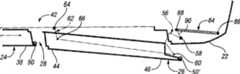
图1是本发明的汽车在前车门和后车门处于关闭位置时的局部透视图;Fig. 1 is a partial perspective view of the automobile of the present invention when the front doors and the rear doors are in closed positions;
图2是图1中的汽车在后车门处于中间位置时的局部透视图;Fig. 2 is a partial perspective view of the car in Fig. 1 when the rear door is in the middle position;
图3是图1中的汽车在后车门处于另一中间位置时的另一个局部透视图;Fig. 3 is another partial perspective view of the car in Fig. 1 when the rear door is in another intermediate position;
图4是图1中的汽车在后车门处于敞开位置时的另一个局部透视图;Figure 4 is another partial perspective view of the automobile of Figure 1 with the rear doors in an open position;
图5是图1中的汽车在前后车门都处于敞开位置时的另一个局部透视图;Fig. 5 is another partial perspective view of the car in Fig. 1 when the front and rear doors are in open positions;
图6是图1中的汽车的前后车门在关闭位置时的俯视局部剖面示意图,图中用虚线示出了处于第二中间位置和敞开位置的后车门;Fig. 6 is a top view partial cross-sectional schematic diagram of the front and rear doors of the automobile in Fig. 1 when they are in the closed position, in which the rear doors in the second intermediate position and the open position are shown by dotted lines in the figure;
图7是图1中的汽车的后车门在关闭位置时的俯视局部剖面图;Fig. 7 is a top partial sectional view of the rear door of the automobile in Fig. 1 when it is in a closed position;
图8是图1中的汽车的后车门在第一中间位置时的俯视局部剖面图;Fig. 8 is a top partial sectional view of the rear door of the automobile in Fig. 1 when it is in the first intermediate position;
图9是图1中的汽车的后车门在第二中间位置时的俯视局部剖面图;Fig. 9 is a top partial sectional view of the rear door of the automobile in Fig. 1 when it is in a second intermediate position;
图10是图1中的汽车的后车门在敞开位置时的俯视局部剖面图;Fig. 10 is a top partial sectional view of the rear door of the automobile in Fig. 1 in an open position;
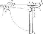
图11是图1中的汽车的后车门前部区域内侧在车门总成内所设的锁机构部分分解时的放大透视图;Fig. 11 is an enlarged perspective view of a partial exploded view of the lock mechanism provided in the door assembly inside the front area of the rear door of the automobile in Fig. 1;
图12是图1中的汽车的车门口的放大透视图,图中示出了与图11中的锁机构扣合的撞销。12 is an enlarged perspective view of the door of the automobile of FIG. 1 showing the striker engaged with the lock mechanism of FIG. 11. FIG.
图13是本发明另一个具有第一车门、第二车门和第三车门的汽车在这些车门处于关闭位置时的局部透视图。FIG. 13 is a partial perspective view of another automobile having a first door, a second door and a third door of the present invention with the doors in a closed position.
图14是图13中的汽车在第三车门处于中间位置时的局部透视图;Fig. 14 is a partial perspective view of the automobile in Fig. 13 when the third door is in an intermediate position;
图15是图13中的汽车在第三车门处于敞开位置时的局部透视图;以及Figure 15 is a partial perspective view of the automobile of Figure 13 with the third door in an open position; and
图16是图13中的汽车在第二车门和第三车门处于敞开位置时的局部透视图。FIG. 16 is a partial perspective view of the automobile of FIG. 13 with the second and third doors in open positions.
具体实施方式Detailed ways
下面根据要求披露了本发明的详细实施例;但是,应该知道,本发明可以采用各种各样的可变通形式予以实施,所披露的实施例只是作为本发明的范例而已。附图并未按比例绘制,为示出特定组件的详细构造,一些特征可能被放大或者缩小。所以本文披露的对具体结构与功能的详细说明不应理解为是对权利要求的限制,而应理解为只是作为解释权利要求,和/或教导本领域的技术人员以各种形式应用本发明的范例基础。Detailed embodiments of the present invention are disclosed below as required; however, it should be understood that the present invention can be implemented in various alternative forms, and the disclosed embodiments are only examples of the present invention. The figures are not to scale and some features may be exaggerated or minimized to show the detailed construction of particular components. Therefore, the detailed description of the specific structures and functions disclosed herein should not be construed as limiting the claims, but should be interpreted as merely explaining the claims, and/or teaching those skilled in the art to apply the present invention in various forms. Example basis.
现在参照图1-5,图中所示为本发明的汽车20。尽管图中显示的汽车20是一辆驾驶室加长型的小型货车,但它可以是本发明精神和范围内所涵盖的任何汽车。Referring now to FIGS. 1-5, there is shown an
在汽车20车身22的一个侧面有一对车门。为了对图1-5中的实施例进行说明,把这对车门称为前车门24和后车门26。不过,应该知道,本文所讨论的前车门24的特征可以加到后车门上,而本文所讨论的后车门26的特征也可以加到前车门上。另外,任一车门24、26的特征都可以加到无论是前面、后面还是侧面空间关系的任一个车门上。比如,可以在运动型多功能车、货车等车辆的后面设置一对相邻的车门。On one side of the
车身22包括车门口28,前车门24和后车门26共同将该车门口关闭并密闭。为使乘客进出方便,车门口28没有安装将驾驶室分为前排30和后排32的中柱,是一个无中柱的车门口。没有中柱(经常称为B柱),车门口28内也就没有什么障碍物,这样便于从车内进出。另外,第二排32通常是用来运货而非乘坐。所以,后排32座椅一般是可折叠的,用于腾出空间来运货。因为没有中柱,所以车门口28的空间被扩大,用于向乘客区内装卸货物。The
现有技术的一方面是提供了分别与车身枢接的前车门和后车门,它们在中央区交叠在一起,所以必须先打开前车门,才能打开和关闭后车门。车门通常是交叠锁在一起的。本发明的汽车20提供了独立开启的车门24、26,从而克服这一局限性。One aspect of the prior art is to provide a front door and a rear door which are pivotally connected to the vehicle body respectively, and they overlap together in the central area, so the front door must be opened before the rear door can be opened and closed. Car doors usually overlap and lock together. The
前车门24铰接在汽车靠近车门口28周边前部区域的位置。前车门24围绕总体竖直的轴线34铰接在车身22上,使得前车门可以从图1-4所示的关闭位置向后拉开至图5所示的敞开位置。前车门24包括传统的锁机构,它将处于关闭位置的车门锁住。前车门24包括用于开启锁机构的外门拉手36和内门拉手,它们可使前车门24的后端38与车身分离。打开锁以后,当车门24围绕靠近前车门24前端40的第一铰链轴线34转动时,前车门24的后端38可以向离开车身22的方向转动。The
前车门24与后车门26一同在车门口28的中央区42会合,将车门口28关闭并密闭。后车门26包括一个前端44,它在车门口28的中央区42与前车门后端38扣合。后车门26还有一个后端46它与车门口28后部区域的一般称为C柱的周边接合。后车门26可以围绕总体竖直的轴线48转动至图4和5所示的敞开位置。因为前车门后端38与后车门前端44在车门口28的中央区42相扣合,所以阻碍了前后车门24、26围绕各自轴线的独立转动开启。因此,其中一扇车门可平移地安装在车身22上,用来先使车门平移,然后将门转开。The
如图1-5所示,后车门26安装在车身22上,能相对车身平移,使后车门前端44与前车门后端28之间隔开一间隙,随后第二车门26就可以转动至敞开位置。As shown in Figures 1-5, the
参照图1,图中后车门26处于关闭位置。随后将后车门26平移到图2所示的第一中间位置。在后车门26的第一中间位置,后车门后端46从车身22外侧平移,同时后车门前端44开始离开前车门后端40向后平移。Referring to FIG. 1 , the
接着将后车门26平移到图3所示的第二中间位置,后车门后端46向离开车身22的方向并相对前车门向后横向平移,同时后车门前端44相对前车门后端38向后平移,而且也是从车身22外侧横向平移。在图3中的第二中间位置,后车门前端44的前缘与前车门后端38分离。后车门后端46的后缘也与车门口28分离。Then the
后车门26到达图3所示的第二中间位置之后,就可以围绕第二铰链轴线48转动至图4所示的敞开位置。这样就可相对前车门24独立地打开后车门26,从而从后排32独立进出。同样,只需向外拉动前车门,它就可以相对后车门被独立地打开。另外,还可以把车门24、26都打开,使无中柱车门口达到最大,用来进/出和装卸货物。After the
现在参照图6,图中所示为前车门24和后车门26的俯视局部剖面图。用实线表示的前车门24与后车门26都处于关闭位置。前车门后端38与后车门前端44交叠在一起。因此它们之间有一个用来密闭车门口28的弹性密封条50。弹性密封条50装在前车门后端28与后车门前端44的其中一端上,使两端之间密闭连接。还可以再装一个弹性密封条50’,使后车门后端46与无中柱车门口28位置的车身22密闭扣合。Referring now to FIG. 6 , a top partial cross-sectional view of the
另外,前车门后端38与后车门前端44交叠在一起,在结构上加强了中央区42对车门系统侧面的结构支撑。在没有B柱的情况下,前车门后端38与后车门前端44的配合为侧面碰撞与倾翻引起的侧面负荷提供了结构支撑。In addition, the
图6中用虚线表示出在第二中间位置的第二车门26,一般用26’表示。第二车门26一旦到达26’的第二中间位置后,就可以转动到仍用虚线表示的一般用附图标记26”表示的敞开位置。The
第二车门26安装在车身22上,能够按固定并且重复的路径平移。当后车门26平移到第二中间位置26’时,后车门后端46向前车门24外侧并向后平移。后车门后端46沿图6中所示的弧形路径52平移。后车门前端44也相对前车门24向后、并相对车身22向外侧平移。后车门前端44也沿着图6所示的弧形路径54平移。The
后车门26从关闭位置到第二中间位置26’的动作,在谈及箱式货车、小型货车和其他车辆使用的滑行门时经常被称为“推开”(kick-out)。后车门后端46与后车门前端44的路径52、54可以与槽、联动装置等相配合设置。后车门后端路径52与后车门前端路径54可以任何足以使后车门26平移到能相对车身22转动后车门26的位置的图形、线形、弧形等形成。与滑动门不同的是,后车门26只平移一足以使其可转动至敞开位置的间隙。The movement of the
第二车门26的平移可完全由四连杆机构,如曲柄滑块机构、四连杆组来实现。如图6所示,设有后连杆56,其固定端58枢接在车身22上。后连杆还有一个远端60,其枢接在后车门后端46上。后连杆远端60使后车门后端46沿路径52平移。另外,后车门26在到达第二中间位置26’后,就能够围绕第二铰链轴线48在后连杆远端60处转动。后车门前端路径54可以由槽、曲柄滑块机构或其他连杆控制形成。The translation of the
现在参照图7-10,图中示出后车门26装在一个联动装置上,用来使后车门26相对车身22平移。图中示出的联动装置是一个四连杆组。车身22充当固定连杆。如上所述,后连杆56枢接在车身和第二车门26上。第二车门26上还装有一个用来使其相对车身22平移的连杆。装有前连杆62,其固定端64与车身22在后连杆56前方的无中柱车门口28内的位置相枢接。前连杆62有一个远端66,其与后车门26相枢接。Referring now to FIGS. 7-10 , the
后连杆56与前连杆62一同使后车门26平移。这样当后连杆56与前连杆62相对车身转动时,后车门26被平移到图8所示的第一中间位置。第一中间位置可以是后连杆56与前连杆62分别沿着相应的弧形路径52、54从图7所示的关闭位置到图9所示的第二中间位置之间的任一中间位置。The
第二中间位置可以是保证后车门后端46与车身22分开的间隙足以使其围绕第二铰链轴线48在后连杆远端66处转动的位置。图9中的第二中间位置还可以是保证后车门前端44与前车门后端38分开的间隙足以使后车门26向离开前车门后端38的方向转动的位置。这样,在到达图9的第二中间位置后,联动装置就可以分开,从而使后车门26能够打开到图10所示的敞开位置。The second intermediate position may be a position that ensures that the rear door
图中示出的后连杆56的连杆长度比前连杆62长,所以后车门后端46与车身侧面分开的平移率要比后车门前端44大。当然,在本发明精神和范围内,任何连杆长度均可考虑。The link length of the
现在参照图11,图中所示为后车门26的内侧,其内装饰板被卸除,暴露出了使图7-10中的联动装置分开的锁机构68。图12中,无中柱车门口28的一块区域内的前连杆62被放大,显示其前连杆远端66上有一个与图11中的锁机构68相配合的撞销70。Referring now to FIG. 11 , there is shown the inside of the
虽然图中所示的锁机构68与前连杆62位于后车门26和无中柱车门口28的下部区域,但是可以想到,本发明的锁机构68和前连杆62可设在后车门26和无中柱车门口28的上部区域。另外,还可以在后车门26和无中柱车门口28的上部与下部区域安装一对锁机构68和一对前连杆62。此外,还可以将锁机构68装在前连杆62上,将撞销70装在后车门26上。Although the
继续参照图11,锁机构68包括传统的接收撞销70并将其锁在内的锁孔72。锁机构68包括从锁孔中放开撞销70的解锁装置74。撞销、锁孔和解锁装置都是车辆门锁机构领域内所熟知的。解锁装置74可以与后车门26的外门拉手76(图1-3)或内门拉手78(图4-5)机械连接。这样用户要将后车门26从中间位置转动到敞开位置,就需要手动将撞销从锁孔72中放开。With continued reference to FIG. 11 , the
同样,用户要打开后车门26,就需要手动将后车门26从关闭位置平移到中间位置。另外,可以给锁机构68装一个驱动解锁装置74的螺形管80。螺线管在收到后车门26处于第二中间位置及用户请求打开后车门26的指示信号后,就可以驱动解锁装置74,使后车门26与前连杆62分开。Similarly, to open the
要关闭后车门26,用户要先转动后车门26,直到锁孔72接收撞销70,将后车门26与前连杆70锁定。随后用户就可以将车门从中间位置平移到关闭位置。可以设置其他的使车门保持在关闭位置的锁或锁定机构。To close the
前连杆62包括一个扭矩弹簧(图中未示出),它装在前连杆固定端64,用于将前连杆62偏压到图12中与联动装置的第二中间位置对应的位置。这样当后车门26转动到第二中间位置时,撞销70就被推到与锁孔72锁合的位置。虽然装在前连杆固定端64上的扭矩弹簧可完全将连杆62偏压到图12中的位置,但并不妨碍车门从第二中间位置平移到关闭位置。The
另外,还可以在车身22内开一个口82,使得锁机构68与撞销70分开后,前连杆62可以穿过该开口82平移到车身22内,以免乘车人抬脚跨进车门口28时绊脚。还可以在后车门26上设有传感器,来确定后车门26正部分转到第二中间位置的时间。收到信号后,驱动器可以使前连杆62向后平移到图12所示的位置。In addition, an
从本发明可以想到,前车门24内也可以安装另一个与固定撞销相配合的锁机构68。It is conceivable from the present invention that another
再次参照图7,图中示出在关闭位置与第二中间位置之间驱动后车门26的线性驱动器84的示意图。该线性驱动器84可以是具有伸长轴的电动步进马达。虽然本文示出且描述的是线性驱动器,但是本发明涵盖任何驱动器,如旋转驱动器,以及任何形式的电源,如弹簧驱动电源、气动电源、液压电源等。Referring again to FIG. 7 , there is shown a schematic diagram of the
线性驱动器84包括与车身22枢接的接地端86。线性驱动器84还包括能从接地端86线性伸长的延长端88。该延长端88与装在后连杆56上的曲柄90相枢接。这样当驱动器84从接地端86向延长端88伸长时,曲柄90就按从图7到图9的逆时针方向驱动后连杆56。The
同样,可以利用驱动器84,使该驱动器84的延长端88向接地端86收缩,将后车门26从图9的第二中间位置平移到图7的关闭位置。延长端80的收缩按从图9到图7的顺时针方向驱动后连杆56的曲柄90。Likewise, the
再参照图7,驱动器84与控制器92相连,该控制器控制驱动器84伸长或收缩。后车门26的外门拉手76和内门拉手78包括手动开关,它们会在相应的拉手76、78被开动后向控制器92发送信号。收到该信号后,控制器92就驱动驱动器84,使后车门26从关闭位置平移到第二中间位置。Referring again to FIG. 7 , the
到达第二中间位置后,控制器92发信号给锁机构68,使前连杆62被放开,这样后车门26就可以被转动到敞开位置。控制器92可以与电子控制单元(ECU)94相连,在将后车门26驱动到第二中间位置或将后车门26开锁之前,来对某些条件进行核查。ECU94可以与传动装置相连,来向控制器92发出让汽车停车的指示。控制器92可以要求汽车停下来以平移后车门26。ECU94可以与发动机或传动装置相连,来向控制器92指明车辆的行驶速度。在平移或解锁后车门26之前,控制器92可以要求车速在一定范围内。另外,控制器92还可以要求汽车停下来,以平移或解锁后车门26。此外,控制器可以92组装到ECU94内。After reaching the second intermediate position, the controller 92 sends a signal to the
驱动器84将后车门26平移到第二中间位置时,驱动器84可以停在这个位置,使得后车门26从敞开位置转动到第二中间位置时,锁机构68的锁孔72对准前连杆62的撞销70。When the
撞销70一进到锁机构68的锁孔72内,锁机构68就可以向控制器92发送信号,指示将后车门26锁定在第二中间位置。随后,控制器92驱动驱动器84从图9所示的伸长位置缩回到图7所示的缩短位置,使后车门26平移到关闭位置。到达图7的关闭位置之后,驱动器84可以停留在其缩短位置,使后车门26锁定在关闭位置。Once the
现在参照图13,图中示出本发明的另一辆汽车96。汽车96包括第一排座椅98,第二排座椅100和第三排座椅102。同样,汽车96包括第一车门104,它与汽车96的车身106枢接在一起。还设有第二车门108和第三车门110,可供进出到第二和第三排座椅100、102内。第二和第三车门108、110一同关闭和密闭在由分成第一排座椅98与第二排座椅100的B柱114和座椅C柱116构成的无中柱车门口112上。Referring now to FIG. 13, another
结合本发明的教导,第二和第三车门108、110可以被独立打开。第二车门108可以从图13-15所示的关闭位置转动到图16所示的敞开位置。同样,使用上述实施例所述的四连杆机构、联动装置等,可以将第三车门110平移到图14所示的中间位置。接着,第三车门110可以从图14的中间位置转动到图15-16所示的敞开位置。通过设置无中柱车门口112,用于进出到图16所示的第二和第三排座椅100、102的车门口空间被扩大。被扩大的车门口112可以用来向第二和第三排座椅100、102内装卸货物。Incorporating the teachings of the present invention, the second and
概括来说,本发明提供了一种车门可以独立打开的用于相邻车门所用无中柱车门口的车门系统。一个车门可铰接在汽车上,而其他车门安装在车上,能够平移并转动至与第一车门分开一间隙,然后能够相对汽车转动。为保证重复性和精确性,提供了固定的平移路径。In summary, the present invention provides a door system for a pillarless doorway used with adjacent doors in which the doors can be opened independently. One door can be hinged on the car, while the other door is mounted on the car, can be translated and rotated to be separated from the first car door by a gap, and then can be rotated relative to the car. A fixed translation path is provided for repeatability and accuracy.
虽然本文详述了实施本发明的各种实施例,但是本发明所属技术领域的技术人员在应用由权利要求限定的本发明时,可以想到各种可变通的设计和实例。While various embodiments for implementing the invention have been described in detail, various alternative designs and examples will occur to those skilled in the art to which this invention belongs in applying the invention defined by the claims.
Claims (19)
Translated fromChineseApplications Claiming Priority (2)
| Application Number | Priority Date | Filing Date | Title |
|---|---|---|---|
| US11/275,182US7488029B2 (en) | 2005-12-16 | 2005-12-16 | Independently opening doors for an automotive door opening |
| US11/275,182 | 2005-12-16 |
Publications (2)
| Publication Number | Publication Date |
|---|---|
| CN1982107A CN1982107A (en) | 2007-06-20 |
| CN1982107Btrue CN1982107B (en) | 2012-05-23 |
Family
ID=38165057
Family Applications (1)
| Application Number | Title | Priority Date | Filing Date |
|---|---|---|---|
| CN2006100903009AExpired - Fee RelatedCN1982107B (en) | 2005-12-16 | 2006-07-13 | Independently opening doors for an automotive door opening |
Country Status (3)
| Country | Link |
|---|---|
| US (1) | US7488029B2 (en) |
| CN (1) | CN1982107B (en) |
| CA (1) | CA2555740C (en) |
Cited By (5)
| Publication number | Priority date | Publication date | Assignee | Title |
|---|---|---|---|---|
| CN107150576A (en)* | 2016-03-03 | 2017-09-12 | 麦格纳覆盖件有限公司 | Rear portion discrepancy latch and sealing system |
| CN107709068A (en)* | 2015-07-24 | 2018-02-16 | 宝马股份公司 | For including at least door system of the car of two row's seats and the method for running this door system |
| CN108474221A (en)* | 2015-10-21 | 2018-08-31 | 伊利诺斯工具制品有限公司 | vehicle door handle |
| CN110978968A (en)* | 2019-12-13 | 2020-04-10 | 北京汽车集团越野车有限公司 | Vehicle with a steering wheel |
| CN111993872A (en)* | 2020-08-26 | 2020-11-27 | 北京汽车集团越野车有限公司 | Vehicle door structure and vehicle with same |
Families Citing this family (46)
| Publication number | Priority date | Publication date | Assignee | Title |
|---|---|---|---|---|
| DE202005005476U1 (en)* | 2005-04-06 | 2006-08-17 | Brose Schließsysteme GmbH & Co.KG | Side door arrangement of a motor vehicle |
| US7845712B2 (en)* | 2007-10-12 | 2010-12-07 | Gm Global Technology Operations, Inc. | Vehicle closure assembly with sealed split between independently selectable closure panels |
| TWI386322B (en)* | 2009-12-15 | 2013-02-21 | Metal Ind Res & Dev Ct | Rotary door opening and closing device |
| US20120049577A1 (en)* | 2010-08-30 | 2012-03-01 | Gm Global Technology Operations, Inc. | Independent opposing-hinged access door |
| US20120049579A1 (en)* | 2010-09-01 | 2012-03-01 | Gm Global Technology Operations, Inc. | Articulating door hinge |
| US8297689B2 (en)* | 2010-09-01 | 2012-10-30 | GM Global Technology Operations LLC | Indexing door latch striker enabling complex door articulation |
| US8342592B2 (en)* | 2010-12-15 | 2013-01-01 | GM Global Technology Operations LLC | Multi link retracting seal surface module |
| GB2490329B (en)* | 2011-04-26 | 2013-12-18 | Nissan Motor Mfg Uk Ltd | Hinged door arrangement for vehicle |
| US20120313394A1 (en)* | 2011-06-13 | 2012-12-13 | Honda Motor Co., Ltd. | Side cargo loading vehicle |
| EP2985161A1 (en) | 2014-08-12 | 2016-02-17 | MAGNA STEYR Engineering AG & Co KG | Vehicle |
| DE202015101740U1 (en)* | 2015-04-09 | 2016-07-13 | DESIGNquadrat GbR (vertretungsberechtigte Gesellschafter Alexander Christ, 50679 Köln, Guido Endert, 42799 Leichlingen, Horst Wergen, 42105 Wuppertal) | The vehicle door system |
| DE102015122579A1 (en)* | 2015-12-22 | 2017-06-22 | Kiekert Ag | Safety device for a motor vehicle with a rotary latch and a protective layer |
| US10384519B1 (en)* | 2016-01-12 | 2019-08-20 | Apple Inc. | Doors with adaptive positioning |
| US9869119B2 (en)* | 2016-02-29 | 2018-01-16 | Faraday&Future Inc. | Systems and methods for operating vehicle doors |
| US9849759B2 (en) | 2016-03-15 | 2017-12-26 | Ford Global Technologies, Llc | Independently operating motor vehicle doors with an articulating door interface |
| KR101786705B1 (en)* | 2016-04-20 | 2017-10-18 | 현대자동차 주식회사 | Opposed opening and closing type door structure of vehicle |
| GB2552814A (en) | 2016-08-10 | 2018-02-14 | Ford Global Tech Llc | Improvements in or relating to city cars |
| US10369870B2 (en) | 2016-08-19 | 2019-08-06 | Ford Global Technologies, Llc | Operating mechanism for rear hinged fully sealed independent side operating doors |
| US10487553B2 (en) | 2016-11-02 | 2019-11-26 | Ford Global Technologies, Llc | Articulating hinge system for independently opening automotive doors |
| US20180298647A1 (en)* | 2017-04-13 | 2018-10-18 | Ford Global Technologies, Llc | Supplemental active lock mechanism for center-opening door assembly |
| DE102017213848A1 (en)* | 2017-08-08 | 2019-02-28 | Volkswagen Aktiengesellschaft | Arrangement and method for opening of portal doors of a vehicle and vehicle with such an arrangement |
| KR102474607B1 (en) | 2017-09-11 | 2022-12-06 | 현대자동차주식회사 | Coach door of vehicle capable of opening and closing regardless of order |
| US10648210B1 (en)* | 2017-09-26 | 2020-05-12 | Apple Inc. | Multi-linkage vehicle door hinge |
| US10780766B2 (en) | 2017-11-27 | 2020-09-22 | Ford Global Technologies, Llc | Vehicle door assemblies |
| RU2691556C1 (en)* | 2018-08-27 | 2019-06-14 | Николай Николаевич Леухин | Car door opening system (versions) and method of its application |
| WO2020106940A1 (en)* | 2018-11-21 | 2020-05-28 | Magna International Inc. | Modular individually operable vehicle door |
| US11525291B2 (en)* | 2019-03-27 | 2022-12-13 | Ford Global Technologies, Llc | Door sealing and timing mechanism for use in coach door configuration for a vehicle |
| JP7388047B2 (en)* | 2019-08-26 | 2023-11-29 | マツダ株式会社 | Vehicle side body structure |
| US11186319B2 (en)* | 2019-10-30 | 2021-11-30 | Nissan North America, Inc. | Vehicle body structure |
| US11305623B2 (en) | 2019-12-06 | 2022-04-19 | Karma Automotive Llc | Sliding and pivoting rear vehicle door |
| US12215527B2 (en) | 2019-12-23 | 2025-02-04 | Magna Closures Inc. | Dual function latch assembly for dual door pillar-less door system and control system for controlling the latch assembly |
| US10871018B1 (en)* | 2020-07-23 | 2020-12-22 | Anthony Emerson, Inc. | Reversible doors for auotmobiles such that the door can electively be opened in a traditional orientation or in the suicide orientation |
| DE102021126521A1 (en)* | 2020-10-21 | 2022-04-21 | Magna Closures Inc. | DUAL FUNCTION LATCH DEVICE AND RETRACTABLE CLOSER AND/OR RETRACTABLE RATCHET DEVICE FOR A TWO DOOR PILLARLESS DOOR SYSTEM AND METHOD OF OPERATION THEREOF |
| CN113232729A (en)* | 2021-05-27 | 2021-08-10 | 吉利汽车研究院(宁波)有限公司 | B-pillar-free vehicle body and vehicle |
| US11926198B2 (en) | 2021-10-14 | 2024-03-12 | Ford Global Technologies, Llc | Side door for a vehicle |
| US12410653B2 (en) | 2021-11-05 | 2025-09-09 | Transportation Ip Holdings, Llc | Touchless control system |
| JP2023092132A (en)* | 2021-12-21 | 2023-07-03 | 株式会社アイシン | vehicle door device |
| WO2023132942A1 (en)* | 2022-01-04 | 2023-07-13 | Preact Technologies, Inc. | Driver tracking |
| WO2023170851A1 (en)* | 2022-03-10 | 2023-09-14 | 三菱自動車工業株式会社 | Vehicle side door structure and collision detection system |
| CN114961489B (en)* | 2022-06-07 | 2024-05-17 | 浙江极氪智能科技有限公司 | Door opening and closing device and vehicle |
| WO2024054560A1 (en)* | 2022-09-09 | 2024-03-14 | Magna International Inc. | Casting housing for a door motion assembly |
| US12304288B2 (en) | 2023-06-12 | 2025-05-20 | Ford Global Technologies, Llc | Sealing system for vehicle closure system |
| FR3154039B1 (en) | 2023-10-16 | 2025-10-10 | Renault S A S | Access device with antagonistic doors |
| FR3154038A1 (en) | 2023-10-16 | 2025-04-18 | Renault S.A.S | Access device with antagonistic doors |
| EP4541991A1 (en) | 2023-10-19 | 2025-04-23 | Wuhan Lotus Cars Co., Ltd. | Power actuated swing and slide door for vehicles and power actuating system |
| FR3154947A1 (en) | 2023-11-07 | 2025-05-09 | Renault S.A.S | Access device for a motor vehicle with opposing doors. |
Citations (4)
| Publication number | Priority date | Publication date | Assignee | Title |
|---|---|---|---|---|
| US6386621B1 (en)* | 2001-08-08 | 2002-05-14 | Ford Global Technologies, Inc. | Reverse opening vehicle door |
| CN1526578A (en)* | 2002-11-05 | 2004-09-08 | ���Դ�������ʽ���� | Vehicle side door structure |
| US6827390B2 (en)* | 2003-03-26 | 2004-12-07 | Honda Giken Kogyo Kabushiki Kaisha | C-pillar and rear door hinge structure for vehicles lacking a B-pillar |
| US6851743B2 (en)* | 2002-05-01 | 2005-02-08 | Toto Tech, Inc. | Slide mechanism for door and structural member assembly |
Family Cites Families (102)
| Publication number | Priority date | Publication date | Assignee | Title |
|---|---|---|---|---|
| US573565A (en)* | 1896-12-22 | Detachable fastening for tool-handles | ||
| US1634656A (en) | 1924-12-23 | 1927-07-05 | Fatoux Raymond Albert | Coach body of automobiles |
| US1676599A (en) | 1926-03-04 | 1928-07-10 | Studebaker Corp | Body construction |
| US1639037A (en) | 1926-06-17 | 1927-08-16 | Arthur J Hollingshead | Automobile body construction |
| US1951863A (en) | 1930-11-10 | 1934-03-20 | Vizcaya Jean Antoine August De | Vehicle body |
| US1869274A (en) | 1931-07-21 | 1932-07-26 | Frank F Phillips | Automobile door lock and post |
| FR745066A (en) | 1931-11-04 | 1933-05-01 | ||
| US2084600A (en) | 1936-09-14 | 1937-06-22 | John W Sparkman | Automobile door construction |
| US2177826A (en) | 1938-04-23 | 1939-10-31 | Hansen Mfg Co A L | Door hinge |
| GB621274A (en) | 1947-02-14 | 1949-04-06 | Sidney William Nobbs | Improvements in or relating to bodywork of private saloon motor cars |
| US2733096A (en) | 1949-01-29 | 1956-01-31 | Unit body frame for automotive vehicle | |
| US2567294A (en) | 1949-06-15 | 1951-09-11 | Freeman H Mcclintock | Vehicle body convertible to ambulance use |
| US2827321A (en) | 1955-01-19 | 1958-03-18 | Gen Motors Corp | Door latch for a pillarless automobile |
| US2870477A (en) | 1955-06-01 | 1959-01-27 | Gen Motors Corp | Hinge |
| US3085297A (en) | 1956-08-28 | 1963-04-16 | Douglas Aircraft Co Inc | Door for pressurized cabin |
| US2937043A (en) | 1958-01-10 | 1960-05-17 | Gen Motors Corp | Mechanical door latch for a pillarless automobile |
| US2997336A (en) | 1959-03-13 | 1961-08-22 | Chrysler Corp | Side loading suburban vehicle |
| US3150408A (en) | 1961-04-04 | 1964-09-29 | Ford Motor Co | Vehicle door hinge |
| US3158395A (en) | 1962-03-16 | 1964-11-24 | Ford Motor Co | Vehicle door and windhsield structure |
| US3149864A (en) | 1962-08-13 | 1964-09-22 | Vonnegut Hardware Company | Latch mechanism |
| US3272552A (en) | 1964-01-15 | 1966-09-13 | Heil Co | Latch and tailgate operating mechanism for truck bodies |
| US3578990A (en)* | 1969-04-02 | 1971-05-18 | Henry Naubereit | Pulse generator timing circuits |
| US3757969A (en) | 1969-06-30 | 1973-09-11 | Smithpac Canada Ltd | Latching arrangement for tailgates |
| US3600742A (en) | 1969-07-07 | 1971-08-24 | Gen Electric | Concealed double-pivot hinge for hinged enclosure |
| DE2105659A1 (en) | 1971-02-06 | 1972-08-10 | Volkswagenwerk Ag, 3180 Wolfsburg | Door arrangements for vehicles, in particular motor vehicles |
| US3666305A (en) | 1970-12-04 | 1972-05-30 | Ford Motor Co | Door latch assembly |
| US3873149A (en) | 1972-04-03 | 1975-03-25 | Helix Corp | Body and tailgate assembly for a truck or similar vehicle |
| JPS5317226Y2 (en) | 1972-05-17 | 1978-05-09 | ||
| US3907357A (en) | 1973-07-05 | 1975-09-23 | Jr William F Davis | Van step well construction |
| JPS5815977Y2 (en) | 1976-10-22 | 1983-03-31 | ヤマハ株式会社 | Keyboard device for electronic musical instruments |
| US4162097A (en) | 1976-11-15 | 1979-07-24 | Royal Industries, Inc. | Vehicle cab structure |
| US4143281A (en) | 1977-05-09 | 1979-03-06 | Appley Robert J | Vehicle for the handicapped |
| JPS53156214U (en) | 1977-05-14 | 1978-12-07 | ||
| US4372603A (en) | 1978-12-18 | 1983-02-08 | Fruehauf Corporation | Double pivot door for cargo vehicles |
| US4358151A (en) | 1979-04-02 | 1982-11-09 | Wood Herman C | Hinged rear window |
| JPS5853158B2 (en) | 1980-08-30 | 1983-11-28 | 日産自動車株式会社 | Automobile opening/closing body locking device |
| JPS59170012U (en) | 1983-04-30 | 1984-11-14 | マツダ株式会社 | car door device |
| JPS59179974U (en) | 1983-05-19 | 1984-12-01 | トヨタ自動車株式会社 | car side door hinge |
| DE3343013C2 (en) | 1983-11-28 | 1995-07-06 | Westfalia Werke Knoebel | Device for stiffening the edges of window openings or the like in the walls of the box bodies of vehicles |
| DE3406433A1 (en) | 1984-02-22 | 1985-08-29 | Geze Gmbh, 7250 Leonberg | LOCKING SYSTEM WITH INTEGRATED CLOSING CONTROLLER |
| US4655499A (en) | 1985-02-22 | 1987-04-07 | Piper Robert J | Door hinge for vehicle |
| DE3537304A1 (en) | 1985-10-19 | 1987-04-23 | Porsche Ag | STRUCTURE FOR CARS |
| DE3624095A1 (en) | 1986-07-17 | 1988-01-28 | Deere & Co | SWIVELING DEVICE |
| US4719665A (en) | 1986-12-11 | 1988-01-19 | General Motors Corporation | Double pivot hinge |
| US4952009A (en) | 1987-06-29 | 1990-08-28 | Morgan Corporation | Curtained doors for vehicle bodies |
| GB8720751D0 (en) | 1987-09-03 | 1987-10-07 | Chase P W | Hinge assemblies |
| US4973103A (en) | 1987-12-11 | 1990-11-27 | Mazda Motor Corporation | Vehicle rear body structure |
| GB8811637D0 (en) | 1988-05-17 | 1988-06-22 | Lotus Group Plc | Vehicle door structure |
| US4930836A (en) | 1988-06-24 | 1990-06-05 | Ford Motor Company | Door assembly for pick-up trucks |
| FR2634426B1 (en) | 1988-07-25 | 1990-10-19 | Peugeot | ARRANGEMENT OF TWO ADJACENT SIDE DOORS OF A MOTOR VEHICLE |
| IT1232365B (en) | 1989-04-07 | 1992-01-28 | O C L A P Srl | DEVICE FOR THE OPENING AND CLOSING OF A SWING ON CAR-IRON-TRAMWAY CARRIAGES |
| US5140316A (en) | 1990-03-22 | 1992-08-18 | Masco Industries, Inc. | Control apparatus for powered vehicle door systems |
| JP2531909Y2 (en) | 1991-08-27 | 1997-04-09 | 池田物産株式会社 | Door mounting structure |
| US5282293A (en) | 1992-06-01 | 1994-02-01 | At&T Bell Laboratories | 180° concealed hinge |
| US5297841A (en) | 1992-12-28 | 1994-03-29 | Ford Motor Company | Cargo door assembly |
| US5316365A (en) | 1993-01-25 | 1994-05-31 | General Motors Corporation | Sliding door closed loop cable closure system with balanced cable tension and varying diameter pulleys |
| US5335958A (en)* | 1993-02-18 | 1994-08-09 | Mcneilus Truck And Manufacturing, Inc. | Automatic positive tailgate latching mechanism |
| US5577793A (en) | 1993-04-21 | 1996-11-26 | Kobasic; Richard A. | Multipurpose highway vehicle |
| US5551197A (en) | 1993-09-30 | 1996-09-03 | Donnelly Corporation | Flush-mounted articulated/hinged window assembly |
| US5398988A (en) | 1993-11-22 | 1995-03-21 | Chrysler Corporation | Vehicle door assembly |
| US5632065A (en) | 1994-07-22 | 1997-05-27 | General Motors Corporation | Extended cab pickup truck concealed cargo door hinge having a spring stop detent |
| US5491875A (en) | 1994-07-22 | 1996-02-20 | General Motors Corporation | Extended cab pickup truck concealed cargo door hinge |
| US5499853A (en) | 1994-08-25 | 1996-03-19 | Pourian; Reza R. | Pocket part for a vehicle door |
| JP2724806B2 (en)* | 1994-09-12 | 1998-03-09 | 本田技研工業株式会社 | Car front body structure |
| US5561887A (en) | 1995-05-08 | 1996-10-08 | Chrysler Corporation | Vehicle double pivot door hinge arrangement |
| SE505897C2 (en)* | 1996-01-08 | 1997-10-20 | Kanerva Pentti | Hinge mechanism for car doors |
| US6059352A (en)* | 1996-01-22 | 2000-05-09 | Ford Global Technologies, Inc. | Door assembly for pick-up trucks |
| US5752737A (en)* | 1996-01-22 | 1998-05-19 | Ford Global Technologies, Inc. | Door reinforcement system for pick-up trucks |
| US5685046A (en)* | 1996-04-12 | 1997-11-11 | Chrysler Corporation | Motor vehicle double pivot hinge |
| US5663520A (en)* | 1996-06-04 | 1997-09-02 | O'gara-Hess & Eisenhardt Armoring Co. | Vehicle mine protection structure |
| US5803516A (en)* | 1996-08-01 | 1998-09-08 | Ford Global Technologies, Inc. | Latch assembly |
| US5896704A (en)* | 1996-08-19 | 1999-04-27 | Daimlerchrysler Corporation | Track arrangement for vehicle sliding door |
| DE19634369C1 (en)* | 1996-08-26 | 1997-09-18 | Daimler Benz Ag | Guide for parallel-sliding door on vehicle bodywork with support element |
| US5749611A (en)* | 1996-08-30 | 1998-05-12 | Chrysler Corporation | Door latch remote control assembly |
| JPH10109662A (en) | 1996-10-04 | 1998-04-28 | Mitsubishi Motors Corp | Car body structure |
| DE19704811C1 (en)* | 1997-02-08 | 1998-10-01 | Webasto Tuersysteme Gmbh | Door hinge mechanism for e.g. motor vehicles |
| US5876086A (en)* | 1997-04-14 | 1999-03-02 | The Budd Company | Multi-piece door with hidden hinge |
| US5951098A (en)* | 1997-08-15 | 1999-09-14 | Fontaine Modification Company | Safety door for right-hand stand-up truck |
| US6089640A (en)* | 1997-08-20 | 2000-07-18 | Chrysler Corporation | Support mechanism for a door of a motor vehicle |
| US5906408A (en)* | 1997-09-10 | 1999-05-25 | Cooper; Herbert | Convertible pickup truck |
| US6196617B1 (en)* | 1997-09-30 | 2001-03-06 | Krystal Koach, Inc. | Rear door structure for a vehicle |
| DE19754417C2 (en)* | 1997-12-09 | 2001-07-26 | Lunke Ventra Automotive Gmbh | Door hinge |
| US6053561A (en)* | 1998-07-16 | 2000-04-25 | Chrysler Corporation | Door assembly for a pick-up truck |
| US6224138B1 (en)* | 1998-09-08 | 2001-05-01 | Ford Global Technologies, Inc. | Vehicle bed trunk compartment |
| US6183039B1 (en)* | 1999-02-05 | 2001-02-06 | Delphi Technologies, Inc. | Pivot and slide door system |
| DE19930322C1 (en)* | 1999-07-02 | 2000-11-02 | Edscha Ag | Automobile door hinge has carrier arm and parallel control arm provided with pivot mountings allowing adjustment for compensating door misalignment |
| US6328365B1 (en)* | 1999-11-15 | 2001-12-11 | Ford Global Technologies, Inc. | Integrated bed drawer assembly for vehicles |
| FR2802966B1 (en)* | 1999-12-23 | 2002-08-16 | Aries Ind Mecanismes Et Decoup | MOTOR VEHICLE REAR DOOR HINGE |
| US6213535B1 (en)* | 2000-01-25 | 2001-04-10 | General Motors Corporation | Articulating closure |
| US6196618B1 (en)* | 2000-01-25 | 2001-03-06 | General Motors Corporation | Hinge system |
| US6305737B1 (en)* | 2000-08-02 | 2001-10-23 | Asc Incorporated | Automotive vehicle door system |
| US6609748B1 (en)* | 2000-09-25 | 2003-08-26 | Ford Global Technologies, Llc | Forward facing rear door assembly for motor vehicles |
| US6382705B1 (en)* | 2001-02-01 | 2002-05-07 | General Motors Corporation | Vehicle independent rear access panel with four bar hinge |
| US7096538B2 (en)* | 2001-08-24 | 2006-08-29 | Ventra Group Inc. | Vehicle door hinge system |
| DE10155220C1 (en)* | 2001-11-09 | 2003-02-13 | Daimler Chrysler Ag | Automobile door with combined pivot-sliding movement allowing opening angle of more than 90 degrees |
| US6629337B2 (en)* | 2001-11-28 | 2003-10-07 | Edscha Roof Systems Inc. | Double-pivot resistance hinge for motor vehicle door |
| DE10233485A1 (en)* | 2001-12-13 | 2003-07-17 | Bosch Gmbh Robert | Locking system for motor vehicle door has locking units that are spaced apart from control unit at location within vehicle door or hatch |
| US6550845B1 (en)* | 2002-01-08 | 2003-04-22 | General Motors Corporation | Side door assembly for vehicles |
| US7178853B2 (en)* | 2002-06-11 | 2007-02-20 | Intier Automotive Closures Inc. | Vehicle door with pivot arm |
| US6942277B2 (en)* | 2003-12-22 | 2005-09-13 | Nissan Technical Center North America, Inc. | Vehicle door hinge assembly |
| US6997504B1 (en)* | 2004-08-03 | 2006-02-14 | General Motors Corporation | Dual pivot hinge assembly for vehicles |
| US7097229B1 (en)* | 2005-05-12 | 2006-08-29 | Gm Global Technology Operations, Inc. | Vehicle closure system |
- 2005
- 2005-12-16USUS11/275,182patent/US7488029B2/ennot_activeExpired - Fee Related
- 2006
- 2006-07-13CNCN2006100903009Apatent/CN1982107B/ennot_activeExpired - Fee Related
- 2006-08-01CACA2555740Apatent/CA2555740C/ennot_activeExpired - Fee Related
Patent Citations (5)
| Publication number | Priority date | Publication date | Assignee | Title |
|---|---|---|---|---|
| US6386621B1 (en)* | 2001-08-08 | 2002-05-14 | Ford Global Technologies, Inc. | Reverse opening vehicle door |
| US6851743B2 (en)* | 2002-05-01 | 2005-02-08 | Toto Tech, Inc. | Slide mechanism for door and structural member assembly |
| CN1526578A (en)* | 2002-11-05 | 2004-09-08 | ���Դ�������ʽ���� | Vehicle side door structure |
| US6966600B2 (en)* | 2002-11-05 | 2005-11-22 | Mazda Motor Corporation | Side door structure of vehicle |
| US6827390B2 (en)* | 2003-03-26 | 2004-12-07 | Honda Giken Kogyo Kabushiki Kaisha | C-pillar and rear door hinge structure for vehicles lacking a B-pillar |
Cited By (9)
| Publication number | Priority date | Publication date | Assignee | Title |
|---|---|---|---|---|
| CN107709068A (en)* | 2015-07-24 | 2018-02-16 | 宝马股份公司 | For including at least door system of the car of two row's seats and the method for running this door system |
| CN107709068B (en)* | 2015-07-24 | 2021-01-01 | 宝马股份公司 | Door system for a passenger car comprising at least two rows of seats and method for operating such a door system |
| CN108474221A (en)* | 2015-10-21 | 2018-08-31 | 伊利诺斯工具制品有限公司 | vehicle door handle |
| CN108474221B (en)* | 2015-10-21 | 2021-03-09 | 伊利诺斯工具制品有限公司 | vehicle door handle |
| US11643855B2 (en) | 2015-10-21 | 2023-05-09 | Illinois Tool Works Inc. | Door handle for vehicle |
| CN107150576A (en)* | 2016-03-03 | 2017-09-12 | 麦格纳覆盖件有限公司 | Rear portion discrepancy latch and sealing system |
| CN107150576B (en)* | 2016-03-03 | 2022-11-08 | 麦格纳覆盖件有限公司 | Rear access door latch and sealing system |
| CN110978968A (en)* | 2019-12-13 | 2020-04-10 | 北京汽车集团越野车有限公司 | Vehicle with a steering wheel |
| CN111993872A (en)* | 2020-08-26 | 2020-11-27 | 北京汽车集团越野车有限公司 | Vehicle door structure and vehicle with same |
Also Published As
| Publication number | Publication date |
|---|---|
| US20070152473A1 (en) | 2007-07-05 |
| US7488029B2 (en) | 2009-02-10 |
| CA2555740C (en) | 2014-04-15 |
| CA2555740A1 (en) | 2007-06-16 |
| CN1982107A (en) | 2007-06-20 |
Similar Documents
| Publication | Publication Date | Title |
|---|---|---|
| CN1982107B (en) | Independently opening doors for an automotive door opening | |
| JP2883631B2 (en) | Car door assembly | |
| US7384092B2 (en) | Selectively retractable armrest for a slidable door | |
| US5398988A (en) | Vehicle door assembly | |
| US10487553B2 (en) | Articulating hinge system for independently opening automotive doors | |
| US7341303B2 (en) | Joint locking device for a convertible roof system | |
| US9821696B1 (en) | Integrated assist handle | |
| US6234565B1 (en) | Dual action bifold door assembly | |
| US20230184016A1 (en) | Modified door operation for a motorized vehicle | |
| US6837535B2 (en) | Convertible roof system | |
| US4540215A (en) | Lock system for removable automobile roof panel | |
| US9783028B1 (en) | Powered dual closure system for vehicles | |
| US20160319585A1 (en) | Vehicle with tailgate | |
| US7837243B2 (en) | Locking assembly for rear door | |
| CN116357179A (en) | Vehicle door device | |
| US2991117A (en) | Automobile door | |
| EP2998141B1 (en) | Vehicle | |
| US2748856A (en) | Foldable vehicle door construction | |
| JP2623676B2 (en) | Car rear door device | |
| EP1323562B1 (en) | Trunk lid arrangement | |
| CA2536180C (en) | Locking assembly for rear door | |
| JP2003148024A (en) | Door lock device for automobile | |
| US12173537B2 (en) | Sliding door device for vehicle | |
| US6499794B1 (en) | Sport utility sliding door | |
| JP4120901B2 (en) | Vehicle door mechanism |
Legal Events
| Date | Code | Title | Description |
|---|---|---|---|
| C06 | Publication | ||
| PB01 | Publication | ||
| C10 | Entry into substantive examination | ||
| SE01 | Entry into force of request for substantive examination | ||
| C14 | Grant of patent or utility model | ||
| GR01 | Patent grant | ||
| CF01 | Termination of patent right due to non-payment of annual fee | ||
| CF01 | Termination of patent right due to non-payment of annual fee | Granted publication date:20120523 Termination date:20200713 |