CN1981702B - Analyte monitoring system with integrated lancing apparatus - Google Patents
Analyte monitoring system with integrated lancing apparatusDownload PDFInfo
- Publication number
- CN1981702B CN1981702BCN2006101605952ACN200610160595ACN1981702BCN 1981702 BCN1981702 BCN 1981702BCN 2006101605952 ACN2006101605952 ACN 2006101605952ACN 200610160595 ACN200610160595 ACN 200610160595ACN 1981702 BCN1981702 BCN 1981702B
- Authority
- CN
- China
- Prior art keywords
- monitoring system
- analyte monitoring
- piercing
- firing
- spring
- Prior art date
- Legal status (The legal status is an assumption and is not a legal conclusion. Google has not performed a legal analysis and makes no representation as to the accuracy of the status listed.)
- Expired - Fee Related
Links
- 239000012491analyteSubstances0.000titleclaimsabstractdescription52
- 238000012544monitoring processMethods0.000titleclaimsabstractdescription49
- 230000007246mechanismEffects0.000claimsabstractdescription50
- 210000001124body fluidAnatomy0.000claimsabstractdescription10
- 239000008280bloodSubstances0.000claimsabstractdescription5
- 210000004369bloodAnatomy0.000claimsabstractdescription5
- 239000010839body fluidSubstances0.000claimsabstractdescription5
- WQZGKKKJIJFFOK-GASJEMHNSA-NGlucoseNatural productsOC[C@H]1OC(O)[C@H](O)[C@@H](O)[C@@H]1OWQZGKKKJIJFFOK-GASJEMHNSA-N0.000claimsabstractdescription4
- 239000008103glucoseSubstances0.000claimsabstractdescription4
- 238000012360testing methodMethods0.000claimsdescription5
- 239000007858starting materialSubstances0.000claims3
- 238000010304firingMethods0.000abstractdescription59
- 230000008878couplingEffects0.000abstractdescription24
- 238000010168coupling processMethods0.000abstractdescription24
- 238000005859coupling reactionMethods0.000abstractdescription24
- 210000001519tissueAnatomy0.000description11
- 230000004913activationEffects0.000description4
- 230000000994depressogenic effectEffects0.000description3
- 210000003722extracellular fluidAnatomy0.000description3
- 238000000034methodMethods0.000description3
- 230000035515penetrationEffects0.000description3
- 230000000717retained effectEffects0.000description3
- 230000000007visual effectEffects0.000description3
- 230000008901benefitEffects0.000description2
- 238000004891communicationMethods0.000description2
- 230000000694effectsEffects0.000description2
- 210000003811fingerAnatomy0.000description2
- 238000003780insertionMethods0.000description2
- 230000037431insertionEffects0.000description2
- 230000037452primingEffects0.000description2
- 239000004793PolystyreneSubstances0.000description1
- 239000013060biological fluidSubstances0.000description1
- -1but not limited toSubstances0.000description1
- 230000008859changeEffects0.000description1
- 238000006243chemical reactionMethods0.000description1
- 238000010276constructionMethods0.000description1
- 230000000881depressing effectEffects0.000description1
- 230000001627detrimental effectEffects0.000description1
- 206010012601diabetes mellitusDiseases0.000description1
- 238000000605extractionMethods0.000description1
- 239000011888foilSubstances0.000description1
- 230000009931harmful effectEffects0.000description1
- 230000036541healthEffects0.000description1
- 230000001939inductive effectEffects0.000description1
- 239000000463materialSubstances0.000description1
- 230000000149penetrating effectEffects0.000description1
- 229920000515polycarbonatePolymers0.000description1
- 239000004417polycarbonateSubstances0.000description1
- 229920000728polyesterPolymers0.000description1
- 229920002223polystyrenePolymers0.000description1
- 230000008569processEffects0.000description1
- 210000003813thumbAnatomy0.000description1
- 239000012780transparent materialSubstances0.000description1
Images


Classifications
- A—HUMAN NECESSITIES
- A61—MEDICAL OR VETERINARY SCIENCE; HYGIENE
- A61B—DIAGNOSIS; SURGERY; IDENTIFICATION
- A61B5/00—Measuring for diagnostic purposes; Identification of persons
- A61B5/145—Measuring characteristics of blood in vivo, e.g. gas concentration or pH-value ; Measuring characteristics of body fluids or tissues, e.g. interstitial fluid or cerebral tissue
- A61B5/14532—Measuring characteristics of blood in vivo, e.g. gas concentration or pH-value ; Measuring characteristics of body fluids or tissues, e.g. interstitial fluid or cerebral tissue for measuring glucose, e.g. by tissue impedance measurement
Landscapes
- Health & Medical Sciences (AREA)
- Life Sciences & Earth Sciences (AREA)
- Physics & Mathematics (AREA)
- Biomedical Technology (AREA)
- Medical Informatics (AREA)
- Biophysics (AREA)
- Pathology (AREA)
- Engineering & Computer Science (AREA)
- Emergency Medicine (AREA)
- Heart & Thoracic Surgery (AREA)
- Optics & Photonics (AREA)
- Molecular Biology (AREA)
- Surgery (AREA)
- Animal Behavior & Ethology (AREA)
- General Health & Medical Sciences (AREA)
- Public Health (AREA)
- Veterinary Medicine (AREA)
- Measurement Of The Respiration, Hearing Ability, Form, And Blood Characteristics Of Living Organisms (AREA)
- Investigating Or Analysing Biological Materials (AREA)
Abstract
Translated fromChinese
Description
Translated fromChinese技术领域technical field
本发明基本上涉及医疗装置和系统,并且尤其涉及穿刺装置和相关系统。The present invention relates generally to medical devices and systems, and in particular to piercing devices and related systems.
背景技术Background technique
诸如糖尿病的多种健康状况,需要监视血液、细胞间液或其它体液样本中分析物的浓度(例如,葡萄糖浓度)。通常,这样的监视需要从目标位置(例如,用户手指上的皮肤组织目标位置)抽取体液样本。从目标位置抽取(也称作“挤出”(expression))体液样本,基本上包括用穿刺装置穿刺皮肤组织目标位置,并且而后从该穿刺位置挤出体液样本。Various health conditions, such as diabetes, require monitoring the concentration of an analyte (eg, glucose concentration) in a sample of blood, interstitial fluid, or other bodily fluid. Typically, such monitoring requires drawing a sample of bodily fluid from a target location (eg, a target location of skin tissue on a user's finger). Extraction (also referred to as "expression") of a body fluid sample from a target site essentially involves piercing skin tissue at the target site with a piercing device, and then expressing a body fluid sample from the puncture site.
常规穿刺装置通常具有刚性壳体壳体和采血针,所述采血针可以装备起来(也称作“起动”)并发射(也称作“射击”),以致从穿刺装置的一端伸出。例如,常规穿刺装置可以包括安装在刚性壳体中的采血针,使得采血针可相对于刚性壳体沿着其纵轴线移动。通常,采血针是用弹簧负载和发射的,在释放弹簧之后,刺入(即,“穿刺”)目标位置(例如,皮肤组织目标位置)。而后可以从已刺入的目标位置挤出生物学液体样本(例如,全血样本或细胞间液(ISF)样本)用于收集和分析。在这些专利文献中描述了常规穿刺装置,例如授予Morita的美国专利No.5,730,753、授予Taylor等人的美国专利No.6,045,567以及授予Douglas等人的美国专利No.6,071,250,上述各专利文献在此全文引入作为参考。Conventional piercing devices typically have a rigid housing housing and a lancet that can be armed (also referred to as "priming") and fired (also referred to as "firing") so as to protrude from one end of the piercing device. For example, a conventional lancing device may include a lancet mounted in a rigid housing such that the lancet is movable relative to the rigid housing along its longitudinal axis. Typically, the lancet is spring loaded and fired, penetrating (ie, "piercing") a target site (eg, a skin tissue target site) after the spring is released. A biological fluid sample (eg, a whole blood sample or an interstitial fluid (ISF) sample) can then be squeezed from the pierced target site for collection and analysis. Conventional piercing devices are described in, for example, U.S. Patent No. 5,730,753 to Morita, U.S. Patent No. 6,045,567 to Taylor et al., and U.S. Patent No. 6,071,250 to Douglas et al., each of which is hereby incorporated in its entirety. Incorporated by reference.
由于各种原因,由常规穿刺装置穿刺皮肤组织目标位置可能是过于疼痛的。首先,发射后的后坐力可能导致采血针再次刺入目标位置,虽然在关于原始采血针刺入点稍微偏斜的点的位置。因此,这样的发射后后坐力可能导致了无意的多次穿刺并增加疼痛。第二,常规穿刺装置可以依靠穿刺弹簧的弹簧常数而限定采血针的刺入深度。然而,随着时间的过去,弹簧常数可能发生改变,因而不利地改变了刺入深度。第三,用户可能注意到从穿刺装置壳体发出的基于突然运动的冲量(即,穿刺的副作用)。预计这样的冲量可能会导致用户不安。而且,常规穿刺装置可能是大型的和不方便使用的。Piercing a target site of skin tissue by conventional piercing devices can be too painful for various reasons. First, the recoil after firing may cause the lancet to re-pierce the target location, albeit at a slightly deflected point with respect to the original lancet penetration point. Thus, such firing recoil may have resulted in unintentional multiple punctures and increased pain. Second, conventional piercing devices can rely on the spring constant of the piercing spring to limit the piercing depth of the lancet. However, over time, the spring constant may change, thereby detrimentally changing the penetration depth. Third, the user may notice a sudden motion-based impulse emanating from the lancing device housing (ie, a side effect of lancing). It is expected that such an impulse could cause uneasiness among users. Also, conventional lancing devices can be bulky and inconvenient to use.
附图说明Description of drawings
通过参考下文中对利用了本发明原理的示意性实施例的详细描述和附图,将更好地理解本发明的特征和优点,其中相同附图标记表示相同元件,附图中:The features and advantages of the present invention will be better understood by reference to the following detailed description of illustrative embodiments utilizing the principles of the invention and the accompanying drawings, wherein like reference numerals represent like elements, in which:
图1是根据本发明典型实施例的穿刺设备的简化透视图;Figure 1 is a simplified perspective view of a lancing device according to an exemplary embodiment of the present invention;
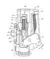
图2是图1的穿刺设备的简化横截面视图;Figure 2 is a simplified cross-sectional view of the piercing device of Figure 1;
图3是图1的穿刺设备的一部分的简化透视图;Figure 3 is a simplified perspective view of a portion of the piercing device of Figure 1;
图4是连接器的简化侧视图,其可与本发明的穿刺设备和分析物监视系统的实施例一起使用;Figure 4 is a simplified side view of a connector that may be used with an embodiment of the piercing device and analyte monitoring system of the present invention;
图5是图4的连接器紧握一体化医疗装置的简化侧视图;Fig. 5 is a simplified side view of the connector gripping integrated medical device of Fig. 4;
图6是图5的连接器和一体化医疗装置的简化内部透视图;Figure 6 is a simplified internal perspective view of the connector and integrated medical device of Figure 5;
图7、8、9和10是图1的穿刺设备在使用中的简化透视图和内部视图,其中箭头A、A’、A”指示穿刺设备的联接臂的运动;Figures 7, 8, 9 and 10 are simplified perspective and internal views of the piercing device of Figure 1 in use, with arrows A, A', A" indicating movement of the coupling arm of the piercing device;
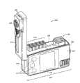
图11是根据本发明典型实施例的分析物监视系统的简化透视图,其中,分析物监视系统的盖子处于打开位置(即第一位置);11 is a simplified perspective view of an analyte monitoring system according to an exemplary embodiment of the present invention, wherein the cover of the analyte monitoring system is in an open position (i.e., a first position);
图12是包含可以与本发明的实施例一起使用的一体化医疗装置的医疗装置包的简化透视和内部视图;Figure 12 is a simplified perspective and interior view of a medical device package containing an integrated medical device that may be used with embodiments of the present invention;
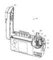
图13是图11的分析物监视系统的简化透视图,示出盖子处于打开位置并且医疗装置包插入分析物监视系统的穿刺设备中;13 is a simplified perspective view of the analyte monitoring system of FIG. 11, showing the cover in an open position and the medical device pack inserted into the piercing device of the analyte monitoring system;
图14是表现了图13的一部分的简化透视图;Figure 14 is a simplified perspective view showing a portion of Figure 13;
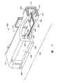
图15是图11的监视系统的盖子和穿刺设备的简化透视图,示出盖子处于闭合位置(即第二位置);以及15 is a simplified perspective view of the cover and piercing device of the monitoring system of FIG. 11, showing the cover in a closed position (i.e., a second position); and
图16是图11的分析物监视系统在用户手(H)中使用的简化透视图。16 is a simplified perspective view of the analyte monitoring system of FIG. 11 in use in a user's hand (H).
具体实施方式Detailed ways
如参考图1中所示的特定实施例在下面详细描述的,根据本发明实施例的穿刺设备包括内部壳体、发射机构、穿刺机构和联接臂。所述发射机构配置成用于在第一方向上产生发射力。穿刺机构配置成用于在第二方向上传送穿刺力,其中第二方向朝向目标位置并且与第一方向相反。联接臂可枢轴转动地连接到壳体,并且具有分别接合到发射机构和穿刺机构的第一和第二端。在使用期间,联接臂的枢转将第一方向上的发射力转换成相反的第二方向上的穿刺力。As described in detail below with reference to the particular embodiment shown in FIG. 1 , a piercing device according to an embodiment of the present invention includes an inner housing, a firing mechanism, a piercing mechanism, and a coupling arm. The firing mechanism is configured to generate a firing force in a first direction. The piercing mechanism is configured to transmit piercing force in a second direction, wherein the second direction is toward the target location and opposite the first direction. A link arm is pivotally connected to the housing and has first and second ends respectively coupled to the firing mechanism and the piercing mechanism. During use, pivoting of the link arm converts a firing force in a first direction into a piercing force in an opposite second direction.
根据本发明实施例的穿刺设备在结构上有益地是紧凑型的,并且结构相对简单。另外,通过将穿刺方向设置成与由发射机构提供的发射力的方向相反,而最小化发射后后坐力,因而有效减少与难以控制的后坐力相关的疼痛。另外,通过将这样的冲量传送到壳体而不是用户上的目标位置,反向的穿刺力和发射力最小化了从穿刺设备发出的基于运动的直线冲量的有害效果。而且,根据本发明的穿刺设备,可以配置成使得与穿刺力相关的第二方向上的动量基本上等于与发射力相关的第一方向上的动量,因此也最小化了基于运动的直线冲量的有害效果。Piercing devices according to embodiments of the present invention are advantageously compact and relatively simple in construction. Additionally, firing recoil is minimized by orienting the puncture in the opposite direction of the firing force provided by the firing mechanism, thereby effectively reducing pain associated with unmanageable recoil. Additionally, the opposing piercing and firing forces minimize the detrimental effects of motion-based linear impulse emanating from the piercing device by delivering such momentum to the housing rather than to a target location on the user. Moreover, according to the piercing device of the present invention, it can be configured such that the momentum in the second direction related to the piercing force is substantially equal to the momentum in the first direction related to the firing force, thus also minimizing the impact of linear impulse based on motion. Harmful effect.
图1是根据本发明典型实施例的用于穿刺目标位置(例如,在用户指尖上的皮肤组织目标位置)的穿刺设备100的简化透视图。图2是穿刺设备100的简化横截面视图,图3是穿刺设备100的一部分的简化透视图。1 is a simplified perspective view of a
参考图1、2和3,穿刺设备100包括内部壳体102、发射机构104、穿刺机构106、联接臂108和起动机构110。内部壳体102包括第一外部表面112、第二外部表面114(窗口115贯穿该第二外部表面114,仅在图15中示出)、内部表面116、内部表面突出部118、导向轨道120、内腔122和开口123。Referring to FIGS. 1 , 2 and 3 ,
如下详细描述的,发射机构104配置成用于在穿刺设备100使用期间,在第一方向上产生发射力。发射机构104包括罩壳124(其具有罩壳远端126、罩壳近端128和罩壳内腔130)、发射弹簧132、触发按钮134和触发弹簧136。As described in detail below,
穿刺机构106配置成用于在穿刺设备100使用期间,在第二方向上发送穿刺力,其中第二方向朝向目标位置并且基本上与发射力的第一方向相反。本领域技术人员将认识到,发射力和穿刺力分别与由发射机构和穿刺机构的移动部件的质量引起的发射动量和穿刺动量相关。而且,因为第二方向基本上与第一方向相反,因此穿刺动量基本上与发射动量相反。如果需要最小化基于运动的直线冲量,可以预先确定发射机构和穿刺机构的移动部件的质量,从而使得穿刺动量和发射动量基本上相等。
穿刺机构106包括穿刺深度调节器138、固定器140、回缩弹簧142(具有回缩弹簧第一端144和回缩弹簧第二端146)、杆148(具有杆第一端150和杆第二端152)、回缩弹簧制动器154和制动器156。另外,穿刺深度调节器138包括阶梯状表面158、帽160和深度调节器弹簧162。The
联接臂108包括枢轴164,并且该联接臂108通过枢轴164可枢轴转动地安装到内部壳体102。联接臂108还包括延伸部分166、钩168、联接臂销170、深度调节器接合部件172、第一端174和第二端176。如在此详细解释的,第一端174与发射机构104接合,并且第二端176与穿刺机构106接合。而且,联接臂108配置成将第一方向上(见图2中的箭头D1)的发射力转换成在基本上相反的第二方向(见图2中的箭头D2)上的穿刺力。应当注意到,D1是沿着发射弹簧132的纵轴线的方向,并且D2沿着杆148纵轴线方向。发射弹簧132连接到联接臂108的第一端174。The
穿刺设备100的起动机构110包括起动杆178(具有起动杆近端180和起动杆远端182)、起动杆弹簧184、起动杆销186、受拉构件188、起动杆枢轴190和凹槽192。
不仅参考图1、2和3,还参考图7、8、9和10,在下详细解释穿刺设备100的操作,以及内部壳体102、发射机构104、穿刺机构106、联接臂108以及起动机构110的功能。Referring not only to FIGS. 1 , 2 and 3 but also to FIGS. 7 , 8 , 9 and 10 , the operation of the piercing
图2示出了与穿刺设备100接合的连接器200和与连接器200接合的一体化医疗装置300。在下面参考图4(用于与本发明的穿刺装置和分析物监视系统一起使用的连接器200的简化侧视图)、图5(图4的连接器紧握一体化医疗装置300的简化侧视图)和图6(图5的连接器和一体化医疗装置的简化内部透视视图),详细描述连接器200和一体化医疗装置300。FIG. 2 shows the
参考图4、5和6,连接器200包括上部条带接合臂202和下部条带接合臂204(其间具有缝隙205)、连接器臂206、狭槽208、条带接合元件210和电导线连接部212。而且,连接器200具有连接器远端214和连接器近端216。条带接合元件210经由多个电导线(未示出)与电导线连接部212电连通。Referring to Figures 4, 5 and 6, the
连接器200配置成以可移除地将一体化医疗装置300保持(即,接合)在上部和下部条带接合臂204和202之间的缝隙205内。如在图4中所示,通过条带接合元件210来接合该一体化医疗装置300。
而且,当连接器200与穿刺设备100可操作地接合时,连接器200被弹簧加载成抵靠该深度调节器弹簧162(见图2)。然而,当受到来自联接臂108的穿刺力时,连接器200可以在内部壳体102中竖直移动(图2的方位上)。换句话说,当连接器200被弹簧加载成抵靠该深度调节器弹簧162时,连接器200可滑动地保持在穿刺设备100中。连接器200的连接器臂206从连接器远端214突出并且接合导向轨道120的内部表面突出部118。Also, the
一体化医疗装置300包括测试条带302(具有测试条带反应区域304)、皮肤组织刺入部件306(具有采血针308)和电接触器310。通过连接器200(例如参见图2和5),一体化医疗装置300可以可操作地连接到穿刺设备100。采血针308配置成可刺破目标位置的皮肤组织,并且提取血液到测试条带反应区域304。本领域技术人员将认识到,可以使用任何合适的一体化医疗装置,包括在国际申请No.PCT/GB01/05634(2002年6月27日公布的WO 02/49507)和美国专利申请公开文本No.2003/0143113A2中描述的那些,上述两者在此全文引入作为参考。The all-in-one
条带接合元件210和连接器200的电导线连接部212配置成可在一体化医疗装置300和分析物监视系统(例如,在下面描述的分析物监视系统400)之间提供电连通。在这点上,条带接合元件210通过电接触器310接触到一体化医疗装置300的测试条带302。在美国专利申请公开文本No.2005/061700A1中包括了对连接器200的进一步描述。
穿刺设备100在此描述为使用连接器200和一体化医疗装置300。然而,本领域技术人员将认识到,可以使用任何合适的方式将穿刺元件连接到穿刺设备100,以及根据本发明实施例的穿刺设备不限于与连接器200和一体化医疗装置300一起使用。
再参考图1、2和3,联接臂108配置成可围绕枢轴164旋转。如在下详细描述的,以这样一种方式来配置该穿刺设备100,即,经由联接臂108的枢转运动,第一方向上的发射力转换成在基本相反的第二方向上的穿刺力。虽然180度代表了第一和第二方向的完全反向,但是在例如180度左右+/-15度的范围中的相反,也足以提供在此描述的益处。该穿刺力导致一体化医疗装置300的采血针308发射进入皮肤组织目标位置。Referring again to FIGS. 1 , 2 and 3 ,
起动杆弹簧184将起动杆178的近端180连接到合适的表面(例如分析物监视系统壳体的内部表面)(在图1-3中未示出)。起动杆178适于围绕起动杆枢轴190旋转。起动杆178的凹槽192配置成保持联接臂108的钩168。受拉构件188在凹口192处将起动杆178的远端182连接到合适的相关组件(例如,如下面参考图15描述的连接到分析物监视系统的盖子)。A
起动杆弹簧184可以连接到合适的相关组件(例如,如下面描述的分析物监视系统的外部系统壳体)。使用起动杆弹簧184将起动杆178放置在合适的位置,在起动了发射机构104之后,起动杆178不干扰该发射机构104。The
一旦获悉了本公开内容,本领域技术人员将认识到,在根据本发明实施例的穿刺装置中使用的起动机构可以对这里所描述的内容采取可替换的形式。例如,一个合适的起动机构可以使用弹簧加载的活塞,以便与钩168协同作用,而不是图1中的特殊的基于杆的起动机构。Those skilled in the art, once apprised of the present disclosure, will recognize that the actuation mechanism used in a piercing device according to an embodiment of the invention may take alternative forms to that described herein. For example, a suitable actuating mechanism could use a spring-loaded piston to cooperate with
当在穿刺设备100的使用期间压下该触发按钮134时,触发按钮134开始发射采血针308进入目标位置。制动器156与连接器200接合并且包括一孔(未示出),其中杆148的第二端152穿过该孔。杆148的第一端150与固定器140接合,使得杆148可以从中滑过。杆148穿过该回缩弹簧142并且经由固定器140连接到第一外部表面112。When the
由弹簧制动器154保持回缩弹簧142的第二端146,并且由固定器140保持回缩弹簧142的第一端144。穿刺设备100的开口123构造成可准备插入和移除该一体化医疗装置300。The
联接臂108的深度调节器接合部件172与穿刺深度调节器138的阶梯状表面158接触,并且用于为用户设置采血针308的目标位置刺入深度。穿刺深度调节器138可以由相对刚性的材料形成,该材料包括但不局限于聚苯乙烯、聚碳酸酯和聚脂或它们的任意组合。The depth
触发弹簧136从触发按钮134延伸至导向轨道120。联接臂销170位于连接器200的狭槽208中(例如,参见图2)。罩壳124用于保持发射弹簧132。而且,发射弹簧132靠在起动杆销186上,并位于罩壳近端128的罩壳内腔130中。因为发射弹簧132基本上放置平行于连接器200并位于其旁边,因此穿刺设备100在长度上相对紧凑。A
图7、8、9和10是使用中的穿刺设备100的简化内部透视图,箭头A、A’、A”指示穿刺设备的联接臂的运动。Figures 7, 8, 9 and 10 are simplified internal perspective views of the piercing
在使用期间,通过促使起动杆178围绕起动杆枢轴190枢转(参见图1),而起动该穿刺设备100,从而在受拉构件188中引起拉力。如图7中所示,随着该起动过程,联接臂108已经围绕其枢轴164逆时针旋转(参见图7的箭头A),并且已经将发射弹簧132压缩成具有在例如约3牛顿到约8牛顿范围中的力。另外,回缩弹簧制动器154已经接触制动器156,并且回缩弹簧142在回缩弹簧制动器154和固定器140之间完全伸展。During use, the piercing
在用户压下触发按钮134之后,连接器200的臂206移动远离该内部表面突出部118。连接器臂206这样的移动释放了该联接臂108,使得该联接臂108在发射弹簧132的偏压下移动。发射弹簧132伸展并围绕其枢轴164顺时针推动联接臂108(参见图8的箭头A’)。当发射弹簧132延展时,联接臂108通过联接臂销170与连接器200上的狭槽208接合。After the user depresses the
当发射弹簧132继续伸展并在联接臂108上施加发射力(在第一方向D1上)时,采血针308从穿刺设备100上伸出以刺入目标位置(参见图9)。这随着发射弹簧132完全伸展而完成,从而导致联接臂108继续围绕枢轴164顺时针旋转(参见图9的箭头A”),使得联接臂108的延伸部分166接触杆148的第二端152。这种接触和相关动量传递了穿刺力(在第二方向D2上),所述穿刺力迫使杆148朝向穿刺设备100的开口123移动,即使仅存在由已伸展的发射弹簧132施加的相对低的力(例如,小于约1.5N)。When the
图9还示出了这样的方式,其中,回缩弹簧制动器154已经移动远离制动器156并朝向穿刺设备100的开口123移动。杆148的移动还压缩了回缩弹簧142(其已经被压缩成具有一定的力,例如,在2牛顿到2.5牛顿范围内的力)。尽管可以将该回缩弹簧142压缩成具有比现在已伸展的发射弹簧132所具有力更大的力,但是联接臂108的动量使其旋转,直到其由于接触到穿刺深度调节器138的阶梯状表面158而停止。该接触阻止了联接臂108的进一步运动。FIG. 9 also shows the manner in which
应当注意到,穿刺深度调节器138用于通过限制联接臂108的运动来调节刺入深度。阶梯状表面158的阶梯状特性允许用户通过从多个阶梯状表面部分中进行选择而确定刺入深度(参见图3),每个阶梯状表面设计成在不同的旋转位置处阻止联接臂108的运动。It should be noted that the piercing
阻止联接臂的进一步运动,导致了与连接器200相关的质量也停止,从而产生了向上的冲量。然而,发射弹簧132的质量和联接臂108的旋转同时停止,产生向下的冲量。由于发射力和穿刺力具有基本上相反的方向,因此该向上的冲量和向下的冲量有益地趋向于互相平衡。Impeding further movement of the link arm causes the mass associated with the
因为向上和向下的冲量关于联接臂108的枢轴164偏移,产生了旋转冲量。然而,因为由导向轨道120引导该连接器200,不会将旋转冲量传送到目标区域,而是传送到了内部壳体并且随后传送到用户的手所具有的相当大的质量。最终效果是旋转冲量不会引人注意和使用户不安。Because the upward and downward momentum is offset about the
在穿刺该目标位置之后,回缩弹簧142的力(例如,2牛顿到2.5牛顿)迫使杆148朝着穿刺设备100的穿刺深度调节器138移动,同时保持与联接臂108的延伸部分166接触(参见图10)。另外,联接臂108保持与连接器200的连接。杆148继续以该方式移动,直到回缩弹簧制动器154接触到制动器156。因此,联接臂108和连接器200通过杆148移而动,同时将采血针308从目标位置内回缩到合适的位置,例如位于目标位置的表面或稍低于目标位置的表面。剩余在发射弹簧132中的小量力保持住联接臂108的该位置,并维持采血针308的位置位于目标位置的表面或稍低于目标位置的表面,使得采血针308可以接触目标位置内的体液或从目标位置挤出的体液。After piercing the target location, the force of the retraction spring 142 (e.g., 2 Newtons to 2.5 Newtons) forces the
图11是根据本发明典型实施例的分析物监视系统400的简化透视图。分析物监视系统400包括外部系统壳体402、与外部系统壳体402一体化的穿刺设备(即,例如图1的穿刺设备100)、以及用于确定体液样本中分析物的测量计(未示出),所述测量计至少部分地容纳在该外部系统壳体中。11 is a simplified perspective view of an
分析物监视系统400还包括在图11中处于打开位置(即,第一位置)的盖子404。盖子404包括皮肤组织接触界面406、铰链408(在图11中未示出,而在图15中所示)、盖子近端410、盖子远端412和外部上部表面413。
分析物监视系统400还包括医疗装置包存储区域414(如图11中示为存储五个医疗装置包500)、可视化显示器416和显示/控制按钮418。而且,外部系统壳体402包括纵向侧面420、第一端422、第二端424以及内部上部表面426。虽然仅为了说明目的而在存储位置示出了五个医疗装置包,但是可以存储任意合适数目的医疗装置包。The
根据本发明实施例的分析物监视系统,可以包括任何合适的测量计,例如包括美国专利No.6,284,125、美国专利No.6,413,410和美国专利申请公开文本No.2003/0143113A2中所记载的基于电化学的测量计,每一个上述专利文件在此全文引入作为参考。Analyte monitoring systems according to embodiments of the present invention may include any suitable meter, including, for example, the electrochemical-based meter, each of which is hereby incorporated by reference in its entirety.
图12是包含一体化医疗装置300的医疗装置包500的简化内部透视图,正如可以存储在分析物监视系统400的医疗装置包存储区域414中那样。医疗装置包500包括本体502,该本体502具有近端504、远端506、第一纵向侧面508、第二纵向侧面510、上部表面512、下部表面(在图12的透视图中未示出)、开口514、内腔516以及一个或多个侧翼518。FIG. 12 is a simplified internal perspective view of a
医疗装置包500还包括覆盖开口514的箔(未示出)。开口514定位在近端504上并且提供了到内腔516的通路。内腔516定位于本体502中,并且配置成可牢固地且可移除地保持该一体化医疗装置300。The
侧翼518提供了将医疗装置包500插入穿刺设备100的机械定位。侧翼518延伸了医疗装置包500的第一和第二纵向侧面508、510的长度。然而,本领域技术人员将认识到,可选择地,这样的侧翼可以沿着纵向侧面508、510中之一或两者部分地延伸,设置在上部表面512上或以其它方式设置在本体502上。
虽然为了描述目的,分析物监视系统400描述为存储以及使用医疗装置包500,但是根据本发明实施例的分析物监视系统可以使用任何合适的医疗装置包。合适的医疗装置包的例子例如在美国专利申请公开文本No.2005/061700A1中有记载。Although for descriptive purposes, the
图13是分析物监视系统400的简化透视图,示出盖子404处于打开位置,并且使用了医疗装置包500’,以将一体化医疗装置插入分析物监视系统的穿刺设备100中。图14是表现图13一部分的简化透视图。图15是图11监视系统的盖子和穿刺设备的简化透视图,示出了盖子处于闭合位置(即,第二位置)。图16是在用户手(H)中使用的图11的分析物监视系统的简化透视图。13 is a simplified perspective view of the
参考图11到16,在下面详细描述了分析物监视系统400的操作。当分析物监视系统400的盖子404闭合时(例如参见图15),在将一体化医疗装置300插入穿刺设备100(参见图14)之后,将盖子404近端410上的皮肤组织接触界面406布置在穿刺设备100的开口123正上方。因而,当压下触发按钮134时,一体化医疗装置300被发射,并且采血针308刺入已经被压靠在皮肤组织接触界面406上(参见图16)的目标位置,例如在用户手H的指尖上的目标位置。The operation of the
应当注意到,在一体化医疗装置300已经与连接器200接合之后并且在盖子404闭合之前,从开口123中移除了医疗装置包500。It should be noted that the
可视化显示器416定位在第一纵向侧面420上,并且提供了可视化界面来指导用户使用分析物监视系统400。显示按钮418设置在第二端424附近的纵向侧面420上,并且用于在使用分析物监视系统400期间输入命令。
盖子404放置在外部上部表面413上的医疗装置包存储区域414之上。盖子404可以部分地或完全地由透明材料形成,从而透过盖子404可以观察到医疗装置包存储区域414的容纳物。铰链408位于盖子404的远端412上。
通过将受拉构件188可操作地连接到铰链408,将盖子404从第一位置(即,打开位置)移动到第二位置(即,闭合位置)就起动了该穿刺设备100(参见图15)。通过在受拉构件188上施加拉伸力,盖子404至第一位置的移动使得起动杆178围绕起动杆枢轴190旋转,从而通过接触联接臂108上的钩168而导致起动杆178逆时针旋转该联接臂108。By operatively connecting the
图15示出了穿刺设备100的窗口115。通过开口115可以读取该医疗装置包500上的刻度代码或其他信息。尽管仅为了说明的目的而在穿刺设备中示出了八个窗口,但是可以采用任意合适数目的窗口。FIG. 15 shows the
特别地参考图16,穿刺设备100的触发按钮134从分析物监视系统400的外部系统壳体402的第一端422伸出。用户可以用包括具有目标位置的手指的一只手(即,图16的手H)握紧和操作该分析物监视系统400。将目标位置压靠该皮肤组织接触界面406,并且用用户的拇指压下触发按钮134。本领域技术人员将认识到,可以采用自动触发来替代手动压下触发按钮134,从而消除了对触发按钮的需要。这样的自动触发例如可以通过用预定力将目标位置压靠该皮肤组织接触界面406而启动。With particular reference to FIG. 16 , the
虽然图11和图13-16示出了根据本发明的分析物监视系统的特定实施例,本领域技术人员将认识到,根据本发明的用于确认体液样本(例如血液)中分析物(例如葡萄糖)的分析物监视系统,总体上包括外部系统壳体、穿刺设备和用于确定分析物的测量计。而且,穿刺设备与外部系统壳体一体化,并且包括内部壳体、发射机构、穿刺机构和联接臂。发射机构配置成用于在第一方向上产生发射力。穿刺机构配置成用于在第二方向上发送穿刺力,其中第二方向朝向目标位置并且与第一方向相反。联接臂可枢轴转动地连接到壳体并且具有分别接合到发射机构和穿刺机构的第一和第二端。在使用期间,联接臂的绕轴旋转将第一方向的发射力转换成相反的第二方向上的穿刺力。这样的穿刺设备相对紧凑并且易于使用,仅需要一只手操作,同时从同一只手上的目标位置中获取体液样本。Although FIGS. 11 and 13-16 illustrate specific embodiments of an analyte monitoring system according to the present invention, those skilled in the art will recognize that a method for confirming an analyte (eg, Glucose) an analyte monitoring system generally includes an external system housing, a piercing device, and a meter for determining an analyte. Also, the piercing device is integrated with the outer system housing and includes an inner housing, a firing mechanism, a piercing mechanism, and a coupling arm. The firing mechanism is configured to generate a firing force in a first direction. The piercing mechanism is configured to send the piercing force in a second direction, wherein the second direction is toward the target location and opposite the first direction. A link arm is pivotally connected to the housing and has first and second ends respectively coupled to the firing mechanism and the piercing mechanism. During use, pivoting of the link arm converts a firing force in a first direction into a piercing force in an opposite second direction. Such piercing devices are relatively compact and easy to use, requiring only one hand to operate while obtaining a sample of bodily fluid from a targeted location on the same hand.
应当理解的是,在实现本发明时,可以使用在此描述的本发明实施例的各种替代方案。意图是,下列权利要求限定本发明的范围,并且因此覆盖这些权利要求的范围内的结构和其等效物。It should be understood that various alternatives to the embodiments of the invention described herein may be employed in practicing the invention. It is intended that the following claims define the scope of the invention and that structures within the scope of these claims and their equivalents be covered thereby.
Claims (11)
Applications Claiming Priority (2)
| Application Number | Priority Date | Filing Date | Title |
|---|---|---|---|
| US11/262,205US20070100256A1 (en) | 2005-10-28 | 2005-10-28 | Analyte monitoring system with integrated lancing apparatus |
| US11/262205 | 2005-10-28 |
Publications (2)
| Publication Number | Publication Date |
|---|---|
| CN1981702A CN1981702A (en) | 2007-06-20 |
| CN1981702Btrue CN1981702B (en) | 2011-05-18 |
Family
ID=37606846
Family Applications (1)
| Application Number | Title | Priority Date | Filing Date |
|---|---|---|---|
| CN2006101605952AExpired - Fee RelatedCN1981702B (en) | 2005-10-28 | 2006-10-30 | Analyte monitoring system with integrated lancing apparatus |
Country Status (4)
| Country | Link |
|---|---|
| US (1) | US20070100256A1 (en) |
| EP (1) | EP1779781A3 (en) |
| JP (1) | JP5086603B2 (en) |
| CN (1) | CN1981702B (en) |
Families Citing this family (68)
| Publication number | Priority date | Publication date | Assignee | Title |
|---|---|---|---|---|
| US6391005B1 (en) | 1998-03-30 | 2002-05-21 | Agilent Technologies, Inc. | Apparatus and method for penetration with shaft having a sensor for sensing penetration depth |
| US8641644B2 (en) | 2000-11-21 | 2014-02-04 | Sanofi-Aventis Deutschland Gmbh | Blood testing apparatus having a rotatable cartridge with multiple lancing elements and testing means |
| US7981056B2 (en) | 2002-04-19 | 2011-07-19 | Pelikan Technologies, Inc. | Methods and apparatus for lancet actuation |
| US9795747B2 (en) | 2010-06-02 | 2017-10-24 | Sanofi-Aventis Deutschland Gmbh | Methods and apparatus for lancet actuation |
| US7041068B2 (en) | 2001-06-12 | 2006-05-09 | Pelikan Technologies, Inc. | Sampling module device and method |
| EP1395185B1 (en) | 2001-06-12 | 2010-10-27 | Pelikan Technologies Inc. | Electric lancet actuator |
| JP4209767B2 (en) | 2001-06-12 | 2009-01-14 | ペリカン テクノロジーズ インコーポレイテッド | Self-optimized cutting instrument with adaptive means for temporary changes in skin properties |
| US7344507B2 (en) | 2002-04-19 | 2008-03-18 | Pelikan Technologies, Inc. | Method and apparatus for lancet actuation |
| US8337419B2 (en) | 2002-04-19 | 2012-12-25 | Sanofi-Aventis Deutschland Gmbh | Tissue penetration device |
| US7749174B2 (en) | 2001-06-12 | 2010-07-06 | Pelikan Technologies, Inc. | Method and apparatus for lancet launching device intergrated onto a blood-sampling cartridge |
| US9427532B2 (en) | 2001-06-12 | 2016-08-30 | Sanofi-Aventis Deutschland Gmbh | Tissue penetration device |
| US9226699B2 (en) | 2002-04-19 | 2016-01-05 | Sanofi-Aventis Deutschland Gmbh | Body fluid sampling module with a continuous compression tissue interface surface |
| US7331931B2 (en) | 2002-04-19 | 2008-02-19 | Pelikan Technologies, Inc. | Method and apparatus for penetrating tissue |
| US7547287B2 (en) | 2002-04-19 | 2009-06-16 | Pelikan Technologies, Inc. | Method and apparatus for penetrating tissue |
| US9795334B2 (en) | 2002-04-19 | 2017-10-24 | Sanofi-Aventis Deutschland Gmbh | Method and apparatus for penetrating tissue |
| US7232451B2 (en) | 2002-04-19 | 2007-06-19 | Pelikan Technologies, Inc. | Method and apparatus for penetrating tissue |
| US8267870B2 (en) | 2002-04-19 | 2012-09-18 | Sanofi-Aventis Deutschland Gmbh | Method and apparatus for body fluid sampling with hybrid actuation |
| US7892183B2 (en) | 2002-04-19 | 2011-02-22 | Pelikan Technologies, Inc. | Method and apparatus for body fluid sampling and analyte sensing |
| US9248267B2 (en) | 2002-04-19 | 2016-02-02 | Sanofi-Aventis Deustchland Gmbh | Tissue penetration device |
| US7674232B2 (en) | 2002-04-19 | 2010-03-09 | Pelikan Technologies, Inc. | Method and apparatus for penetrating tissue |
| US7976476B2 (en) | 2002-04-19 | 2011-07-12 | Pelikan Technologies, Inc. | Device and method for variable speed lancet |
| US7297122B2 (en) | 2002-04-19 | 2007-11-20 | Pelikan Technologies, Inc. | Method and apparatus for penetrating tissue |
| US8784335B2 (en) | 2002-04-19 | 2014-07-22 | Sanofi-Aventis Deutschland Gmbh | Body fluid sampling device with a capacitive sensor |
| US8221334B2 (en) | 2002-04-19 | 2012-07-17 | Sanofi-Aventis Deutschland Gmbh | Method and apparatus for penetrating tissue |
| US8360992B2 (en) | 2002-04-19 | 2013-01-29 | Sanofi-Aventis Deutschland Gmbh | Method and apparatus for penetrating tissue |
| US7491178B2 (en) | 2002-04-19 | 2009-02-17 | Pelikan Technologies, Inc. | Method and apparatus for penetrating tissue |
| US8372016B2 (en) | 2002-04-19 | 2013-02-12 | Sanofi-Aventis Deutschland Gmbh | Method and apparatus for body fluid sampling and analyte sensing |
| US9314194B2 (en) | 2002-04-19 | 2016-04-19 | Sanofi-Aventis Deutschland Gmbh | Tissue penetration device |
| US7901362B2 (en) | 2002-04-19 | 2011-03-08 | Pelikan Technologies, Inc. | Method and apparatus for penetrating tissue |
| US7229458B2 (en) | 2002-04-19 | 2007-06-12 | Pelikan Technologies, Inc. | Method and apparatus for penetrating tissue |
| US8579831B2 (en) | 2002-04-19 | 2013-11-12 | Sanofi-Aventis Deutschland Gmbh | Method and apparatus for penetrating tissue |
| US7708701B2 (en) | 2002-04-19 | 2010-05-04 | Pelikan Technologies, Inc. | Method and apparatus for a multi-use body fluid sampling device |
| US7909778B2 (en) | 2002-04-19 | 2011-03-22 | Pelikan Technologies, Inc. | Method and apparatus for penetrating tissue |
| US8702624B2 (en) | 2006-09-29 | 2014-04-22 | Sanofi-Aventis Deutschland Gmbh | Analyte measurement device with a single shot actuator |
| US8574895B2 (en) | 2002-12-30 | 2013-11-05 | Sanofi-Aventis Deutschland Gmbh | Method and apparatus using optical techniques to measure analyte levels |
| DE602004028463D1 (en) | 2003-05-30 | 2010-09-16 | Pelikan Technologies Inc | METHOD AND DEVICE FOR INJECTING LIQUID |
| US7850621B2 (en) | 2003-06-06 | 2010-12-14 | Pelikan Technologies, Inc. | Method and apparatus for body fluid sampling and analyte sensing |
| WO2006001797A1 (en) | 2004-06-14 | 2006-01-05 | Pelikan Technologies, Inc. | Low pain penetrating |
| US8282576B2 (en) | 2003-09-29 | 2012-10-09 | Sanofi-Aventis Deutschland Gmbh | Method and apparatus for an improved sample capture device |
| EP1680014A4 (en) | 2003-10-14 | 2009-01-21 | Pelikan Technologies Inc | METHOD AND DEVICE FOR A VARIABLE USER INTERFACE |
| US8668656B2 (en) | 2003-12-31 | 2014-03-11 | Sanofi-Aventis Deutschland Gmbh | Method and apparatus for improving fluidic flow and sample capture |
| US7822454B1 (en) | 2005-01-03 | 2010-10-26 | Pelikan Technologies, Inc. | Fluid sampling device with improved analyte detecting member configuration |
| WO2006011062A2 (en) | 2004-05-20 | 2006-02-02 | Albatros Technologies Gmbh & Co. Kg | Printable hydrogel for biosensors |
| US9775553B2 (en) | 2004-06-03 | 2017-10-03 | Sanofi-Aventis Deutschland Gmbh | Method and apparatus for a fluid sampling device |
| WO2005120365A1 (en) | 2004-06-03 | 2005-12-22 | Pelikan Technologies, Inc. | Method and apparatus for a fluid sampling device |
| US8652831B2 (en) | 2004-12-30 | 2014-02-18 | Sanofi-Aventis Deutschland Gmbh | Method and apparatus for analyte measurement test time |
| US8636672B2 (en)* | 2007-02-28 | 2014-01-28 | Nipro Diagnostics, Inc. | Test strip with integrated lancet |
| US20100081968A1 (en)* | 2005-07-15 | 2010-04-01 | Home Diagnostics, Inc. | Test Strip With Integrated Lancet |
| FI121698B (en)* | 2005-07-19 | 2011-03-15 | Ihq Innovation Headquarters Oy | Health monitoring device and sensor cassette for the health monitoring device |
| JP4957121B2 (en)* | 2006-08-22 | 2012-06-20 | 住友電気工業株式会社 | Biosensor cartridge |
| WO2009031314A1 (en)* | 2007-09-04 | 2009-03-12 | Panasonic Corporation | Blood analysis device |
| US20090099437A1 (en)* | 2007-10-11 | 2009-04-16 | Vadim Yuzhakov | Lancing Depth Adjustment Via Moving Cap |
| EP2221000B1 (en)* | 2007-11-27 | 2012-09-19 | ARKRAY, Inc. | Puncture device |
| EP2265324B1 (en) | 2008-04-11 | 2015-01-28 | Sanofi-Aventis Deutschland GmbH | Integrated analyte measurement system |
| EP2375986B1 (en) | 2008-12-18 | 2013-12-11 | Facet Technologies, LLC | Lancing device |
| US9375169B2 (en) | 2009-01-30 | 2016-06-28 | Sanofi-Aventis Deutschland Gmbh | Cam drive for managing disposable penetrating member actions with a single motor and motor and control system |
| EP2542886A1 (en)* | 2010-03-05 | 2013-01-09 | B. Braun Melsungen AG | System and method for monitoring at least one blood parameter |
| US8965476B2 (en) | 2010-04-16 | 2015-02-24 | Sanofi-Aventis Deutschland Gmbh | Tissue penetration device |
| US9167992B2 (en) | 2010-11-03 | 2015-10-27 | Roche Diabetes Care, Inc. | Lancet drive system depth control method and test strip location methods |
| US9237904B2 (en) | 2010-12-06 | 2016-01-19 | Panasonic Healthcare Holdings Co., Ltd. | Puncturing instrument |
| US8158428B1 (en) | 2010-12-30 | 2012-04-17 | General Electric Company | Methods, systems and apparatus for detecting material defects in combustors of combustion turbine engines |
| US20120172759A1 (en)* | 2010-12-30 | 2012-07-05 | Roche Diagnostics Operations, Inc. | Handheld Medical Diagnostic Devices With Lancing Depth Control |
| US8852123B2 (en) | 2010-12-30 | 2014-10-07 | Roche Diagnostics Operations, Inc. | Handheld medical diagnostic devices housing with sample transfer |
| US9717452B2 (en) | 2010-12-30 | 2017-08-01 | Roche Diabetes Care, Inc. | Handheld medical diagnostic devices with lancing speed control |
| WO2013070488A1 (en)* | 2011-11-08 | 2013-05-16 | Facet Technologies, Llc | Lancing device with cam-actuated drive and separate guidance |
| CA2857503C (en) | 2011-12-15 | 2020-10-27 | Facet Technologies, Llc | Latch mechanism for preventing lancet oscillation in a lancing device |
| JP6429770B2 (en) | 2012-06-18 | 2018-11-28 | ファセット テクノロジーズ エルエルシーFacet Technologies, LLC | One-way drive mechanism for puncture device |
| US9000866B2 (en) | 2012-06-26 | 2015-04-07 | University Of Dayton | Varactor shunt switches with parallel capacitor architecture |
Citations (3)
| Publication number | Priority date | Publication date | Assignee | Title |
|---|---|---|---|---|
| US4230118A (en)* | 1977-08-05 | 1980-10-28 | Holman Rury R | Automatic lancet |
| US6228100B1 (en)* | 1999-10-25 | 2001-05-08 | Steven Schraga | Multi-use lancet device |
| CN1456891A (en)* | 2002-05-09 | 2003-11-19 | 生命扫描有限公司 | Continuous strips for liquid sample tester and their manufacture, package and use |
Family Cites Families (18)
| Publication number | Priority date | Publication date | Assignee | Title |
|---|---|---|---|---|
| US4924879A (en)* | 1988-10-07 | 1990-05-15 | Brien Walter J O | Blood lancet device |
| US5196025A (en)* | 1990-05-21 | 1993-03-23 | Ryder International Corporation | Lancet actuator with retractable mechanism |
| AUPN363995A0 (en)* | 1995-06-19 | 1995-07-13 | Memtec Limited | Electrochemical cell |
| US6413410B1 (en)* | 1996-06-19 | 2002-07-02 | Lifescan, Inc. | Electrochemical cell |
| WO1997004707A1 (en)* | 1995-07-28 | 1997-02-13 | Apls Co., Ltd. | Assembly for adjusting piercing depth of lancet |
| US5951493A (en)* | 1997-05-16 | 1999-09-14 | Mercury Diagnostics, Inc. | Methods and apparatus for expressing body fluid from an incision |
| US6045567A (en)* | 1999-02-23 | 2000-04-04 | Lifescan Inc. | Lancing device causing reduced pain |
| DE19948759A1 (en)* | 1999-10-09 | 2001-04-12 | Roche Diagnostics Gmbh | Blood lancet device for drawing blood for diagnostic purposes |
| US6607543B2 (en)* | 2000-06-13 | 2003-08-19 | Bayer Corporation | Lancing mechanism |
| KR100788305B1 (en)* | 2001-01-12 | 2007-12-27 | 아크레이 인코퍼레이티드 | Puncture device, its manufacture method, pump mechanism and suction device |
| US6929649B2 (en)* | 2002-04-23 | 2005-08-16 | Lifescan, Inc. | Lancing device with automatic stick and return |
| US20030212344A1 (en)* | 2002-05-09 | 2003-11-13 | Vadim Yuzhakov | Physiological sample collection devices and methods of using the same |
| US20030143113A2 (en)* | 2002-05-09 | 2003-07-31 | Lifescan, Inc. | Physiological sample collection devices and methods of using the same |
| CA2444630A1 (en)* | 2002-10-15 | 2004-04-15 | Bayer Healthcare Llc | Lancing device |
| US7617932B2 (en)* | 2003-09-19 | 2009-11-17 | Diabetes Diagnostics, Inc. | Medical device package, kit and associated methods |
| US20060247671A1 (en)* | 2005-05-02 | 2006-11-02 | Levaughn Richard W | Compact, multi-use micro-sampling device |
| US20070060842A1 (en)* | 2005-08-29 | 2007-03-15 | Manuel Alvarez-Icaza | Lancing cap kit applied pressure sensing cap |
| US20070100364A1 (en)* | 2005-10-28 | 2007-05-03 | Sansom Gordon G | Compact lancing apparatus |
- 2005
- 2005-10-28USUS11/262,205patent/US20070100256A1/ennot_activeAbandoned
- 2006
- 2006-10-25JPJP2006289435Apatent/JP5086603B2/ennot_activeExpired - Fee Related
- 2006-10-27EPEP06255534Apatent/EP1779781A3/ennot_activeWithdrawn
- 2006-10-30CNCN2006101605952Apatent/CN1981702B/ennot_activeExpired - Fee Related
Patent Citations (3)
| Publication number | Priority date | Publication date | Assignee | Title |
|---|---|---|---|---|
| US4230118A (en)* | 1977-08-05 | 1980-10-28 | Holman Rury R | Automatic lancet |
| US6228100B1 (en)* | 1999-10-25 | 2001-05-08 | Steven Schraga | Multi-use lancet device |
| CN1456891A (en)* | 2002-05-09 | 2003-11-19 | 生命扫描有限公司 | Continuous strips for liquid sample tester and their manufacture, package and use |
Also Published As
| Publication number | Publication date |
|---|---|
| JP5086603B2 (en) | 2012-11-28 |
| EP1779781A2 (en) | 2007-05-02 |
| CN1981702A (en) | 2007-06-20 |
| JP2007125383A (en) | 2007-05-24 |
| US20070100256A1 (en) | 2007-05-03 |
| EP1779781A3 (en) | 2009-07-29 |
Similar Documents
| Publication | Publication Date | Title |
|---|---|---|
| CN1981702B (en) | Analyte monitoring system with integrated lancing apparatus | |
| EP1779780A2 (en) | Compact lancing apparatus | |
| US7438694B2 (en) | Lancing device | |
| EP1031319B1 (en) | Lancing device having a releasable connector | |
| EP2004058B1 (en) | Lancing device | |
| EP1415593B1 (en) | Lancing device | |
| US8709033B2 (en) | Trigger activated lancet | |
| US20060247670A1 (en) | Lancing device with automatic lancet release | |
| US5871494A (en) | Reproducible lancing for sampling blood | |
| JP4663656B2 (en) | Insertion device for infusion set | |
| CN1964667B (en) | Squeeze-activated medical puncturing device | |
| CN106687040B (en) | First drop removal lancet device | |
| JPH03141929A (en) | Lancet ejecting mechanism | |
| AU5011901A (en) | Lancing mechanism | |
| WO1993009723A1 (en) | Lancet device | |
| JP2007536013A (en) | Cam-operated medical puncture device and method | |
| EP2381847B1 (en) | Skin pricking device | |
| JP7669064B2 (en) | Blood collection device and method of use | |
| EP1847219B1 (en) | Lancing device | |
| HK1104202A (en) | Compact lancing apparatus | |
| HK1104163A (en) | Analyte monitoring system with integrated lancing apparatus | |
| AU668533C (en) | Lancet device | |
| MXPA06008844A (en) | Dampening and retraction mechanism for a lancing device |
Legal Events
| Date | Code | Title | Description |
|---|---|---|---|
| C06 | Publication | ||
| PB01 | Publication | ||
| C10 | Entry into substantive examination | ||
| SE01 | Entry into force of request for substantive examination | ||
| C14 | Grant of patent or utility model | ||
| GR01 | Patent grant | ||
| CF01 | Termination of patent right due to non-payment of annual fee | Granted publication date:20110518 Termination date:20191030 | |
| CF01 | Termination of patent right due to non-payment of annual fee |