CN1976639B - Lymph node detector - Google Patents
Lymph node detectorDownload PDFInfo
- Publication number
- CN1976639B CN1976639BCN2005800220424ACN200580022042ACN1976639BCN 1976639 BCN1976639 BCN 1976639BCN 2005800220424 ACN2005800220424 ACN 2005800220424ACN 200580022042 ACN200580022042 ACN 200580022042ACN 1976639 BCN1976639 BCN 1976639B
- Authority
- CN
- China
- Prior art keywords
- image
- lymph node
- wavelength
- illumination light
- light source
- Prior art date
- Legal status (The legal status is an assumption and is not a legal conclusion. Google has not performed a legal analysis and makes no representation as to the accuracy of the status listed.)
- Expired - Lifetime
Links
Images


Classifications
- A—HUMAN NECESSITIES
- A61—MEDICAL OR VETERINARY SCIENCE; HYGIENE
- A61B—DIAGNOSIS; SURGERY; IDENTIFICATION
- A61B10/00—Instruments for taking body samples for diagnostic purposes; Other methods or instruments for diagnosis, e.g. for vaccination diagnosis, sex determination or ovulation-period determination; Throat striking implements
- A—HUMAN NECESSITIES
- A61—MEDICAL OR VETERINARY SCIENCE; HYGIENE
- A61B—DIAGNOSIS; SURGERY; IDENTIFICATION
- A61B5/00—Measuring for diagnostic purposes; Identification of persons
- A61B5/0059—Measuring for diagnostic purposes; Identification of persons using light, e.g. diagnosis by transillumination, diascopy, fluorescence
- A—HUMAN NECESSITIES
- A61—MEDICAL OR VETERINARY SCIENCE; HYGIENE
- A61B—DIAGNOSIS; SURGERY; IDENTIFICATION
- A61B5/00—Measuring for diagnostic purposes; Identification of persons
- A61B5/41—Detecting, measuring or recording for evaluating the immune or lymphatic systems
- A61B5/414—Evaluating particular organs or parts of the immune or lymphatic systems
- A61B5/415—Evaluating particular organs or parts of the immune or lymphatic systems the glands, e.g. tonsils, adenoids or thymus
- A—HUMAN NECESSITIES
- A61—MEDICAL OR VETERINARY SCIENCE; HYGIENE
- A61B—DIAGNOSIS; SURGERY; IDENTIFICATION
- A61B5/00—Measuring for diagnostic purposes; Identification of persons
- A61B5/41—Detecting, measuring or recording for evaluating the immune or lymphatic systems
- A61B5/414—Evaluating particular organs or parts of the immune or lymphatic systems
- A61B5/418—Evaluating particular organs or parts of the immune or lymphatic systems lymph vessels, ducts or nodes
- G—PHYSICS
- G01—MEASURING; TESTING
- G01N—INVESTIGATING OR ANALYSING MATERIALS BY DETERMINING THEIR CHEMICAL OR PHYSICAL PROPERTIES
- G01N21/00—Investigating or analysing materials by the use of optical means, i.e. using sub-millimetre waves, infrared, visible or ultraviolet light
- G01N21/17—Systems in which incident light is modified in accordance with the properties of the material investigated
- G01N21/25—Colour; Spectral properties, i.e. comparison of effect of material on the light at two or more different wavelengths or wavelength bands
- G01N21/27—Colour; Spectral properties, i.e. comparison of effect of material on the light at two or more different wavelengths or wavelength bands using photo-electric detection ; circuits for computing concentration
- G—PHYSICS
- G01—MEASURING; TESTING
- G01N—INVESTIGATING OR ANALYSING MATERIALS BY DETERMINING THEIR CHEMICAL OR PHYSICAL PROPERTIES
- G01N21/00—Investigating or analysing materials by the use of optical means, i.e. using sub-millimetre waves, infrared, visible or ultraviolet light
- G01N21/62—Systems in which the material investigated is excited whereby it emits light or causes a change in wavelength of the incident light
- G01N21/63—Systems in which the material investigated is excited whereby it emits light or causes a change in wavelength of the incident light optically excited
- G01N21/64—Fluorescence; Phosphorescence
- A—HUMAN NECESSITIES
- A61—MEDICAL OR VETERINARY SCIENCE; HYGIENE
- A61B—DIAGNOSIS; SURGERY; IDENTIFICATION
- A61B2562/00—Details of sensors; Constructional details of sensor housings or probes; Accessories for sensors
- A61B2562/02—Details of sensors specially adapted for in-vivo measurements
- A61B2562/0233—Special features of optical sensors or probes classified in A61B5/00
- A—HUMAN NECESSITIES
- A61—MEDICAL OR VETERINARY SCIENCE; HYGIENE
- A61B—DIAGNOSIS; SURGERY; IDENTIFICATION
- A61B2562/00—Details of sensors; Constructional details of sensor housings or probes; Accessories for sensors
- A61B2562/04—Arrangements of multiple sensors of the same type
- A61B2562/043—Arrangements of multiple sensors of the same type in a linear array
- A—HUMAN NECESSITIES
- A61—MEDICAL OR VETERINARY SCIENCE; HYGIENE
- A61B—DIAGNOSIS; SURGERY; IDENTIFICATION
- A61B5/00—Measuring for diagnostic purposes; Identification of persons
- A61B5/06—Devices, other than using radiation, for detecting or locating foreign bodies ; Determining position of diagnostic devices within or on the body of the patient
Landscapes
- Health & Medical Sciences (AREA)
- Life Sciences & Earth Sciences (AREA)
- Physics & Mathematics (AREA)
- General Health & Medical Sciences (AREA)
- Pathology (AREA)
- Engineering & Computer Science (AREA)
- Veterinary Medicine (AREA)
- Medical Informatics (AREA)
- Molecular Biology (AREA)
- Surgery (AREA)
- Animal Behavior & Ethology (AREA)
- Biomedical Technology (AREA)
- Public Health (AREA)
- Heart & Thoracic Surgery (AREA)
- Immunology (AREA)
- Biophysics (AREA)
- Vascular Medicine (AREA)
- Endocrinology (AREA)
- Chemical & Material Sciences (AREA)
- Analytical Chemistry (AREA)
- Biochemistry (AREA)
- General Physics & Mathematics (AREA)
- Nuclear Medicine, Radiotherapy & Molecular Imaging (AREA)
- Mathematical Physics (AREA)
- Theoretical Computer Science (AREA)
- Spectroscopy & Molecular Physics (AREA)
- Investigating, Analyzing Materials By Fluorescence Or Luminescence (AREA)
- Endoscopes (AREA)
- Investigating Or Analysing Materials By Optical Means (AREA)
Abstract
Description
Translated fromChinese技术领域technical field
本发明涉及利用由荧光色素发出的荧光像检测前哨淋巴结(sentinel lymph node)等淋巴结的淋巴结检测装置。The present invention relates to a lymph node detecting device for detecting a lymph node such as a sentinel lymph node using a fluorescent image emitted by a fluorescent dye.
背景技术Background technique
前哨淋巴结,是指癌细胞从肿瘤经淋巴流最初到达的、癌细胞转移的可能性最高的淋巴结。因此,如果正确地确认了前哨淋巴结,且看不到癌细胞在此处的转移,则认为不向其它脏器转移。由此,可以期待患者的肉体上·精神上的负担的大幅度减轻以及由于切除手术的省略而引起的治疗费的控制等。The sentinel lymph node refers to the lymph node where cancer cells first arrive from the tumor through the lymphatic flow and where the possibility of cancer cell metastasis is the highest. Therefore, if the sentinel lymph node is correctly confirmed and no metastasis of cancer cells can be seen there, it is considered that there is no metastasis to other organs. Thereby, a substantial reduction of the physical and mental burden on the patient, control of treatment costs due to omission of resection operations, and the like can be expected.
作为检测前哨淋巴结的方法,已知主要有色素法和RI(放射性同位素)法。在色素法中,将靛蓝胭脂红等的蓝色色素注入肿瘤附近,通过目视追踪被染成蓝色的淋巴管,将最初到达的淋巴结作为前哨淋巴结检测出。此外,在RI法中,在肿瘤附近注入成为示踪剂的放射性同位素,从皮肤上用γ射线探针探索设想为含有同位素最初到达并蓄积的淋巴结的生物体观察部位,将感知了γ射线的生物体观察部位作为前哨淋巴结检测出。As a method for detecting a sentinel lymph node, mainly a dye method and an RI (radioisotope) method are known. In the pigment method, a blue pigment such as indigo carmine is injected into the vicinity of the tumor, and the lymphatic vessels dyed blue are visually traced, and the lymph nodes that first arrive are detected as sentinel lymph nodes. In addition, in the RI method, a radioactive isotope used as a tracer is injected near the tumor, and a gamma-ray probe is used to probe the observation site of the living body that is supposed to contain the lymph node where the isotope first arrives and accumulates from the skin, and the gamma-ray-sensed The biological observation site was detected as a sentinel lymph node.
此外,还提出有使用了荧光色素的前哨淋巴结的确认方法。在特开2001-299676号日本公开特许公报(文献1)中公开的前哨淋巴结检测装置中,预先在肿瘤附近注入荧光色素,在设想为包含其周围的前哨淋巴结的生物体观察部照射规定波长的光作为激发光。然后,将从该生物体观察部发出的近红外波长波段的荧光像转换显示为可视化像,由此进行前哨淋巴结的确认。In addition, a method for confirming sentinel lymph nodes using a fluorescent dye has also been proposed. In the sentinel lymph node detection device disclosed in Japanese Patent Laid-Open No. 2001-299676 (Document 1), a fluorescent dye is injected into the vicinity of the tumor in advance, and the living body observation part assumed to include the surrounding sentinel lymph nodes is irradiated with fluorescein of a predetermined wavelength. light as excitation light. Then, the sentinel lymph node is confirmed by converting and displaying the fluorescence image in the near-infrared wavelength range emitted from the living body observation part into a visualized image.
此外,关于荧光测定法,在特开平11-332820号日本公开特许公报(文献2)、特开2000-292353号日本公开特许公报(文献3)中也有记载。In addition, the fluorescence measurement method is also described in JP-A-11-332820 (Document 2) and JP-A-2000-292353 (Document 3).
发明内容Contents of the invention
但是,在上述现有技术的色素法中,存在需要用于通过目视追踪染成蓝色的淋巴管的丰富的经验、以及一旦看丢了前哨淋巴结的位置需要反复染色等的问题。However, in the above-mentioned conventional dye method, there are problems such as the need for extensive experience in visually tracing the lymphatic vessels dyed blue, and the need for repeated staining once the position of the sentinel lymph node is lost.
此外,在上述现有技术的RI法中,虽然不需要通过目视追踪淋巴管的上述的经验或者反复染色,但是存在由于使用放射线核素周围被曝露在放射线下的危险性以及放射性同位素价格高等的问题。In addition, in the RI method of the above-mentioned prior art, although the above-mentioned experience or repeated staining by visual tracking of lymphatic vessels is not required, there is a risk of exposure to radiation due to the use of radionuclides and the high price of radioisotopes. The problem.
并且,虽然在使用了荧光色素的文献1的前哨淋巴结检测装置中,没有曝露的危险性,但为了得到一般图像使用由可视光形成的照明光,与透过荧光的滤波器不同,需要用于透过可视光的滤波器。并且,需要用于使由荧光形成的像与由可视光形成的像重合的光学手段,由于构成复杂,存在在医疗现场的操作困难这样的问题。In addition, although there is no risk of exposure in the sentinel lymph node detection device of Document 1 that uses a fluorescent dye, in order to obtain a general image, the illumination light formed by visible light is used, which is different from the filter that transmits fluorescence. filter for passing visible light. In addition, an optical means for superimposing an image formed by fluorescence and an image formed by visible light is required, and there is a problem that operation at a medical site is difficult due to a complicated structure.
另一方面,在上述文献2和文献3中,虽然记载了由激发光源以外的光源形成的图像的取得,但该图像只不过是荧光观察图像的修改用数据。On the other hand, in the
本发明是为了解决以上的问题而做出的,目的是提供装置构成简单且淋巴结的位置的检测容易的淋巴结检测装置。The present invention was made to solve the above problems, and an object of the present invention is to provide a lymph node detection device with a simple device configuration and easy detection of the position of a lymph node.
为了达到这样的目的,本发明的淋巴结检测装置,其特征在于,具备:向包括在预先注入有发出规定波长的荧光的荧光色素的肿瘤附近的淋巴结在内的生物体观察部照射激发光的激发光源;在包括由照射激发光而从生物体观察部发出的荧光的波长的透过波长波段内透过光的光学滤波器;向生物体观察部照射被设定为包含在透过波长波段的波长的照明光的照明光源;由发生自生物体观察部发出的荧光形成构成、且透过光学滤波器的荧光像,以及由照明光因生物体观察部的而形成的反射构成、且透过光学滤波器的普通像进行摄像,并输出各自对应的荧光观察图像和普通观察图像的摄像装置;将从摄像设备输出的荧光观察图像和普通观察图像作为用于检测淋巴结的图像进行显示的图像显示装置。另外,优选上述的透过波长波段的下限的波长大于激发光的波长。In order to achieve such an object, the lymph node detection device of the present invention is characterized in that it includes an excitation device for irradiating excitation light to a living body observation part including a lymph node near a tumor in which a fluorochrome emitting fluorescence of a predetermined wavelength has been previously injected. a light source; an optical filter that transmits light in a transmission wavelength band including the wavelength of fluorescence emitted from the living body observation part by irradiation with excitation light; The illumination light source of the illumination light of the wavelength; the fluorescent image formed by the fluorescence emitted from the biological observation part and transmitted through the optical filter, and the reflection of the illumination light by the biological observation part and transmitted through the optical filter An imaging device that captures the normal image of the filter and outputs the corresponding fluorescence observation image and normal observation image; an image display device that displays the fluorescence observation image and the normal observation image output from the imaging device as an image for lymph node detection . In addition, it is preferable that the wavelength of the lower limit of the above-mentioned transmission wavelength band is longer than the wavelength of the excitation light.
上述的淋巴结检测装置是可显示荧光观察图像和普通观察图像二者的构成。因此,可以将荧光观察图像和普通观察图像进行比较,可以在生物体观察部内容易地检测淋巴结的位置。此外,光学滤波器在包括从生物体观察部发出的荧光的波长的透过波长波段中透过光。并且,照明光被设定为其波长包括在上述的透过波长波段。因此,在1个光学滤波器中,可以透过由从生物体观察部发出的荧光形成的荧光像和由照明光在生物体观察部的反射光形成的普通像二者。此外,这样,虽然使荧光像和普通像透过,但可以不使用2个不同的光学滤波器,所以不需要使荧光像和普通像重合用的光学设备。因此,构成变得简单,可以得到小型化了的简便且廉价的装置。此外,照明光的波长,如上所述,被设定在光学滤波器的透过波长波段内。因此,与使用白色光的情况相比,可以抑制由在摄像时发生的像差引起的模糊。这样的检测装置,在上述的前哨淋巴结的检测中十分有用。The above-mentioned lymph node detection device is configured to be able to display both the fluorescence observation image and the normal observation image. Therefore, the fluorescence observation image can be compared with the normal observation image, and the position of the lymph node can be easily detected in the living body observation part. In addition, the optical filter transmits light in a transmission wavelength band including a wavelength of fluorescence emitted from the living body observation portion. In addition, the wavelength of the illumination light is set to be included in the above-mentioned transmission wavelength band. Therefore, both the fluorescent image formed by the fluorescence emitted from the living body observation part and the normal image formed by the reflected light of the illuminating light on the living body observation part can be transmitted through one optical filter. Also, in this way, although the fluorescence image and the normal image are transmitted, it is not necessary to use two different optical filters, so an optical device for superimposing the fluorescence image and the normal image is unnecessary. Therefore, the configuration becomes simple, and a downsized, simple and inexpensive device can be obtained. In addition, the wavelength of the illumination light is set within the transmission wavelength band of the optical filter as described above. Therefore, compared with the case of using white light, it is possible to suppress blur caused by aberrations occurring at the time of imaging. Such a detection device is very useful in the detection of the above-mentioned sentinel lymph node.
这里,优选照明光源向生物体观察部上照射设定在荧光的波长附近的波长的照明光。由此,可以使用透过波长波段狭窄的光学滤波器,光学滤波器的得到变得容易。Here, it is preferable that the illumination light source irradiates the living body observation portion with illumination light having a wavelength set in the vicinity of the wavelength of fluorescence. Accordingly, an optical filter having a narrow transmission wavelength band can be used, and the optical filter can be easily obtained.
此外,优选还具备一体地支撑激发光源和照明光源的支撑部件,支撑部件与摄像装置设备为一体。由于将激发光源、照明光源和摄像装置设置为一体的构成,可以以简单的装置构成实现操作容易的装置。In addition, it is preferable to further include a support member integrally supporting the excitation light source and the illumination light source, and the support member is integrated with the imaging device. Since the excitation light source, the illumination light source, and the imaging device are integrally provided, an easy-to-operate device can be realized with a simple device configuration.
此时,优选激发光源和照明光源在支撑部件的同一面上以规定的配置关系进行设置。由此,对于生物体观察部的规定范围的激发光和照明光的照射的控制变得容易。At this time, it is preferable that the excitation light source and the illumination light source are provided in a predetermined arrangement relationship on the same surface of the supporting member. This facilitates the control of irradiation of excitation light and illumination light within a predetermined range of the living body observation unit.
优选,支撑部件具有支撑激发光源和照明光源的第1主面,和在与该第1主面交叉的方向上形成贯通的孔的面,光学滤波器设置在孔内。根据该构成,可以提供激发光源、照明光源和光学滤波器的定位容易且由于简单的装置构成而使操作容易的装置。Preferably, the support member has a first main surface that supports the excitation light source and the illumination light source, and a surface that forms a through hole in a direction intersecting the first main surface, and the optical filter is provided in the hole. According to this configuration, it is possible to provide a device in which the positioning of the excitation light source, the illumination light source, and the optical filter is easy, and the operation is easy due to the simple device configuration.
优选,支撑部件是板状的部件,具有与第1主面相对的第2主面,摄像设备以相对于孔的方式被支撑在第2主面上。根据这样的构成,摄像装置相对于光学滤波器的定位也变得容易。Preferably, the supporting member is a plate-shaped member having a second main surface opposite to the first main surface, and the imaging device is supported on the second main surface so as to face the hole. According to such a configuration, positioning of the imaging device with respect to the optical filter is also facilitated.
本发明的淋巴结检测装置可以具备多个上述激发光源和多个上述照明光源。优选多个激发光源和多个照明光源在规定的方向上交替设置而成的多个列,在第1主面上,在垂直于该规定的方向的方向上以规定的间隔排列。根据该构成,相对于生物体观察部的规定范围,可以将激发光和照明光进行更均匀地照射。The lymph node detection device of the present invention may include a plurality of the excitation light sources and a plurality of the illumination light sources. Preferably, a plurality of columns in which a plurality of excitation light sources and a plurality of illumination light sources are alternately arranged in a predetermined direction are arranged at predetermined intervals in a direction perpendicular to the predetermined direction on the first main surface. According to this configuration, the excitation light and the illumination light can be irradiated more uniformly with respect to the predetermined range of the living body observation unit.
优选,在多个激发光源和多个照明光源中,设置在孔的周围的激发光源和照明光源各自的出射方向,向孔的中心轴线倾斜。根据该构成,相对于生物体观察部的规定范围,可以将激发光和照明光进行更均匀地照射。Preferably, among the plurality of excitation light sources and the plurality of illumination light sources, the emission directions of the excitation light sources and the illumination light sources arranged around the hole are inclined toward the central axis of the hole. According to this configuration, the excitation light and the illumination light can be irradiated more uniformly with respect to the predetermined range of the living body observation unit.
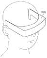
此外,优选图像显示设备能够安装在观察者的头部上。由此,在观察时不需要用手保持淋巴结检测装置,可以增大观察以外的操作的自由度。Furthermore, it is preferable that the image display device can be mounted on the observer's head. This eliminates the need to hold the lymph node detection device by hand during observation, and the degree of freedom in operations other than observation can be increased.
附图说明Description of drawings
图1是前哨淋巴结检测装置的第1实施方式的构成图。FIG. 1 is a configuration diagram of a first embodiment of a sentinel lymph node detection device.
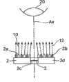
图2是表示在图1所示的检测装置中所使用的光源单元的构成的正面图。FIG. 2 is a front view showing the configuration of a light source unit used in the detection device shown in FIG. 1 .
图3是表示相对于光的波长的光学滤波器的透过率的图。FIG. 3 is a graph showing the transmittance of an optical filter with respect to the wavelength of light.
图4是表示关于生物体观察部的(a)荧光观察图像、(b)普通观察图像、(c)重叠观察图像的示意图。4 is a schematic view showing (a) a fluorescence observation image, (b) a normal observation image, and (c) a superimposed observation image of a living body observation unit.
图5是表示在观察者的头部安装图1中所示的检测装置的样子的立体图。FIG. 5 is a perspective view showing how the detection device shown in FIG. 1 is attached to the observer's head.
图6是表示用于图1所示的检测装置的光源单元的其它构成的平面图。6 is a plan view showing another configuration of a light source unit used in the detection device shown in FIG. 1 .
具体实施方式Detailed ways
以下,结合附图详细说明本发明的淋巴结检测装置的优选的实施方式。另外,在附图的说明中对相同要素标记相同符号,省略重复的说明。此外,附图的尺寸比例,也不一定与说明的一致。Hereinafter, preferred embodiments of the lymph node detection device of the present invention will be described in detail with reference to the accompanying drawings. In addition, in the description of the drawings, the same reference numerals are assigned to the same elements, and overlapping descriptions are omitted. In addition, the dimensional ratios in the drawings are not necessarily consistent with the descriptions.
图1是本发明的淋巴结检测装置的前哨淋巴结检测装置的第1实施方式的构成图。图2是表示在图1所示的检测装置中所使用的光源单元的构成的正面图。以下,参照图1和图2,说明本实施方式的前哨淋巴结检测装置的构成。此外,在图1和图2中,为了容易看,对照明光源标注斜线而表示。关于光线,用实线表示从激发光和荧光色素发出的荧光,用虚线表示照明光和在生物体观察部上的照明光的反射光。FIG. 1 is a configuration diagram of a first embodiment of a sentinel lymph node detection device of the lymph node detection device of the present invention. FIG. 2 is a front view showing the configuration of a light source unit used in the detection device shown in FIG. 1 . Hereinafter, the configuration of the sentinel lymph node detection device according to the present embodiment will be described with reference to FIGS. 1 and 2 . In addition, in FIG. 1 and FIG. 2 , the illumination light sources are shown with oblique lines for easy visibility. Regarding the light rays, the excitation light and the fluorescence emitted by the fluorochrome are shown by solid lines, and the illumination light and the reflected light of the illumination light on the living body observation part are shown by dotted lines.
本前哨淋巴结检测装置1是,对于包括在人体等的生物体中的前哨淋巴结21的生物体观察部20,通过观察由从生物体观察部20中的荧光色素发出的荧光所形成的像(荧光像)以及照明光12由生物体观察部20产生的反射光所形成的像(普通像13),而检测前哨淋巴结21的。The present sentinel lymph node detection device 1 observes an image formed by fluorescence emitted from a fluorescent dye in the living body observation part 20 (fluorescence image) and the image (ordinary image 13 ) formed by the reflected light generated by the living
在使用本检测装置1的前哨淋巴结的检测中,在生物体观察部20内的肿瘤附近预先注入荧光色素。然后,观察来自蓄积在前哨淋巴结21中的荧光色素的荧光而检测淋巴结。In the detection of the sentinel lymph node using the detection device 1 , a fluorescent dye is preliminarily injected into the vicinity of the tumor in the living
作为荧光色素,可以使用考虑检测装置1的具体的构成等而适当选择的荧光色素,而作为这种荧光色素的例子可以举出吲哚花青绿。As the fluorescent dye, one appropriately selected in consideration of the specific configuration of the detection device 1 and the like can be used, and an example of such a fluorescent dye includes indocyanine green.
在图1中所示的检测装置1具备光源单元2、光学滤波器3、照射控制装置4、摄像装置5、控制单元6、图像显示装置7、图像记录装置8。The detection device 1 shown in FIG. 1 includes a
光源单元2具有多个激发光源2a、多个照明光源2b和支撑板2d。多个激发光源2a,由将各个相同波长的光作为激发光10出射的光源形成,用于对包括前哨淋巴结21的生物体观察部20照射激发光10。The
另一方面,多个照明光源2b,由将各个相同波长的光作为照明光12出射的光源形成,用于对包括前哨淋巴结21的生物体观察部20照射照明光12。On the other hand, the plurality of
作为激发光源2a和照明光源2b,优选使用半导体激光(LD)或发光二极管(LED).此外,由激发光源2a供给的激发光10的波长,可以基于用于观察的荧光色素的光吸收特性等,从可激发荧光色素的波长中选择.As the
关于从照明光源2b供给的照明光12的波长,选择设定为包含在后述的光学滤波器3的透过波长波段中的波长,优选选择用于观察的荧光色素发出的荧光波长附近的波长。The wavelength of the
支撑板2d,如图2所示,是将激发光源2a和照明光源2b一体支撑的支撑部件。光源单元2的光轴Ax与支撑板2d的中心轴一致。在支撑板2d中,在中央位置设置有包括光轴即其中心轴Ax的开口部2c。该开口部2c,由沿着轴线Ax设置的划成贯通孔的面构成。The
此外,激发光源2a和照明光源2b,在支撑板2d的前面2e上,即第1主面上,以围绕开口部2c的方式2维排列。具体而言,激发光源2a和照明光源2b,如图2所示,在前面2e上,在与矩形支撑板2d的一边平行的方向上,以一定的排列间隔dx交替排列,并形成多个1维排列。这些1维排列,向其1维排列方向错开仅dx/2,同时在与该1维排列垂直的方向上,以一定的排列间隔dy排列,构成2维排列。但是,在开口部2c中,不设置这些光源。此外,前表面2e,是相对于光源单元2的中心轴Ax垂直的面,是相对于激发光10和照明光12的照射对象的生物体观察部20成为前表面的面。In addition, the
开口部2c用于,使从光源单元2的前方入射的荧光像和普通像13向后方通过。荧光像是指对生物体观察部20照射规定波长的激发光10,由从被激发的生物体观察部20发出的荧光11所形成的像。此外,普通像13是指由照明光12通过生物体观察部20的反射光所形成的像。The
图6是表示用于图1中所示的检测装置的光源单元的其它构成的平面图。在这样的构成中,为了防止由于开口部2c的影响向生物体观察部20照射的激发光10和照明光12的强度分布在中央减弱,优选将开口部2c附近的激发光源2a和照明光源2b的光轴朝向中心轴Ax倾斜设置。6 is a plan view showing another configuration of a light source unit used in the detection device shown in FIG. 1 . In such a configuration, in order to prevent the intensity distribution of the
此外,在支撑板2d的开口部2c内设置有光学滤波器3。光学滤波器3,切断激发光10的反射光,并且在包括由生物体观察部20发出的荧光的波长在内的透过波长波段上使光透过。图3是表示使用吲哚花青绿作为荧光色素时的相对于光波长的光学滤波器3的透过率的图。图的横轴表示光的波长(nm),一个纵轴表示相对于波长的光学滤波器3的透过率,另一个纵轴表示光的强度。此外,由图3的实线所形成的曲线a、b、c表示光的波长波段及其强度分布,a表示激发光10的特性,b表示照明光12的特性,c表示荧光11的特性。另一方面,由图3的虚线形成的曲线d表示光学滤波器3的相对于光的波长的透过率。如图3所示,光学滤波器3切断激发光10,透过照明光12和荧光11。Moreover, the
这里,激发光10的波长,如上所述,选自能够激发荧光色素的波长。因此,在使用吲哚花青绿作为荧光色素时,由于其光吸收区域在近红外波长波段,因此,如图3的曲线a所示,作为激发光10,可以适当选择使用近红外波长波段内的波长(例如波长750nm)。此时,从生物体观察部20发出的荧光的荧光极大波长,如图3的c所示,为845nm。Here, the wavelength of the
此外,光学滤波器3的透过波长波段,选择为切断激发光10且包括从生物体观察部20发出的荧光11的波长。在图3中所示的例中,如曲线d所示,光学滤波器3的透过波长波段是比激发光10的波长750nm长的波长,且以小于荧光的波长波段波长的波长λc为下限值,并透过大于λc的波长(包括波长λc)侧的光的波长波段。透过波长波段的光以100%的透过率透过。In addition, the transmission wavelength band of the
并且,照明光12的波长,选择设定为包含在光学滤波器3的透过波长波段中的波长,优选从观察用荧光色素发出的荧光波长附近的波长。因此,如图3的曲线b所示,选择波长840nm的光作为照明光12。In addition, the wavelength of the
作为该光学滤波器3,优选使用具有不仅有下限值也有上限值的透过波长波段的光学滤波器。此外,光学滤波器3优选设置在摄像装置5的透镜的前部或内部。As the
此外,照射控制装置4,与光源单元2连接,并控制由激发光源2a和照明光源2b形成的激发光10和照明光12的照射。作为激发光10和照明光12的照射的控制,例如,可以进行光的照射定时、照射时间或者出射的光的强度的控制。Furthermore, the
在光源单元2的后方侧设置有摄像装置5。在本实施方式中,该摄像装置5,以使光轴Ax一致的状态,与光源单元2的支撑板2d一体设置。例如,摄像装置5,以与由开口部2c划成的孔相对的方式,由与前表面2e相对的后表面2f(第2主面)来支撑。由此,荧光像和普通像13,通过支撑板2d的开口部2c,透过光学滤波器3,到达摄像装置5。摄像装置5,将入射的荧光像和普通像13摄像,将各自对应的荧光观察图像和普通观察图像作为图像数据进行输出。An imaging device 5 is provided on the rear side of the
作为摄像装置5,例如,可以使用可取得2维图像的CCD照相机。特别优选,在该摄像装置5中,使用可对荧光像的波长波段(通常由于以800nm前后的荧光观察图像为对象,而为近红外的波长波段)的光进行高灵敏度摄像的摄像装置。此外,对于多个激发光源2a、多个照明光源2b和摄像装置5,可以根据需要分别连接光源用电源和摄像装置用电源。但是,在图1中省略关于电源等的图示。此外,这些装置也可以使用由电池驱动的。As the imaging device 5, for example, a CCD camera capable of acquiring two-dimensional images can be used. In particular, it is preferable to use an imaging device capable of high-sensitivity imaging of light in the wavelength range of fluorescence images (generally, the near-infrared wavelength range because fluorescence observation images around 800 nm are targeted) as the imaging device 5 . In addition, a power source for a light source and a power source for an imaging device may be respectively connected to the plurality of
对从摄像装置5输出的荧光观察图像和普通观察图像,设置控制单元6。控制单元6,根据需要进行荧光观察图像或普通观察图像的调整、切换或这些观察图像的重叠。此外,对于从摄像装置5向控制单元6的图像数据的传送,可以使用通过有线或无线的传送方法。A control unit 6 is provided for the fluorescence observation image and the normal observation image output from the imaging device 5 . The control unit 6 adjusts and switches the fluorescence observation images or common observation images or overlaps these observation images as required. Furthermore, for the transmission of image data from the imaging device 5 to the control unit 6, a transmission method by wire or wireless can be used.
控制单元6具有图像调整部6a和图像控制部6b。图像调整部6a,对从摄像装置5输出的荧光观察图像或普通观察图像,自动或手动进行亮度、对比度的调整。The control unit 6 has an
图像控制部6b构成为,在检测装置1中,可以切换显示荧光观察图像和普通观察图像,以及可使它们重合并同时显示。因此,图像控制部6b具有重叠图像形成部6c和图像切换部6d。为了进行切换显示,图像切换部6d可以通过自动或手动切换显示的观察图像。此外,为了进行重合显示,重叠图像形成部6c,重叠从摄像装置5输出的荧光观察图像和普通观察图像,形成重叠观察图像。The
此外,控制单元6与照射控制装置4连接。Furthermore, the control unit 6 is connected to the
图像显示装置7和图像记录装置8连接在控制单元6。在图像显示装置7的显示部7a中,将从控制单元6输出的观察图像的图像数据,作为用于检测前哨淋巴结21的观察图像进行显示。作为该图像显示装置7,例如,可以使用CRT监视器或安装有作为摄像装置5的CCD照相机的液晶显示器等。此外,图像记录装置8是用于记录从控制单元6输出的图像数据的记录设备。作为该图像记录装置8,例如可以使用将图像数据记录在记录介质录像磁带的磁带录像机等。The
对使用图1所示的前哨淋巴结检测装置1的前哨淋巴结的检测方法进行说明。首先,在肿瘤附近注入荧光色素吲哚花青绿。经过规定的时间后,吲哚花青绿经过淋巴流到达前哨淋巴结21。A method of detecting a sentinel lymph node using the sentinel lymph node detection device 1 shown in FIG. 1 will be described. First, the fluorescent dye indocyanine green is injected near the tumor. After a defined period of time, indocyanine green travels through the lymphatic stream to the
接着,在取得荧光观察图像时,对包括该前哨淋巴结21的生物体观察部20,由激发光源2a照射波长750nm的激发光10。由此,从该生物体观察部20发出近红外波长波段的荧光像。之后,该荧光像透过光学滤波器3,由作为摄像装置5的CCD照相机进行摄像。被摄像的荧光观察图像,向控制单元6输出,因此,在该处根据需要进行调整后,在图像显示装置7的显示部7a进行显示。Next, when acquiring a fluorescence observation image, the living
另一方面,在取得普通观察图像时,由照明光源2b对包括该前哨淋巴结21的生物体观察部20照射波长840nm的照明光12。由此,得到由生物体观察部20引起的照明光12的反射光形成的普通像13。另外,照明光12的波长设定为,在光学滤波器3的透过波长波段内,优选设定在从吲哚花青绿发出的荧光的波长附近。然后,该普通像13透过光学滤波器3,由作为摄像装置5的CCD照相机进行摄像。将被摄像的普通观察图像,向控制单元6输出,在该处根据需要进行调整等后,在图像显示装置7的显示部7a进行显示。On the other hand, when acquiring a normal observation image, the living
此外,在取得重叠观察图像时,首先按照上述的方法,在控制单元6中取得荧光观察图像和普通观察图像。其后,在重叠图像形成部6c中对它们进行重叠,形成重叠观察图像。将形成的重叠观察图像,输出到图像显示装置7,在图像显示装置7的显示部7a中进行显示。In addition, when obtaining the superimposed observation image, first, the control unit 6 obtains the fluorescence observation image and the normal observation image according to the method described above. Thereafter, these are superimposed in the superimposed
这些观察图像的显示,由控制单元6的图像控制部6b控制为,可以将各观察图像切换显示,或者由重叠观察图像重合并同时显示。此外,除了重叠观察图像以外,作为将荧光观察图像和普通观察图像重合并同时显示的方法,例如有将普通观察图像预先显示在图像显示装置7的显示部7a上作为黑白图像后,将在其上重叠着色后的荧光观察图像并进行显示的方法。由此,也可以同时显示荧光观察图像和普通观察图像。The display of these observation images is controlled by the
此外,控制单元6与照射控制装置4连接。照射控制装置4,根据被显示的观察图像,例如用机械开关或电开关等控制激发光源2a和照明光源2b的照射。由此,可对照射进行各种控制,例如,为了交替显示荧光观察图像和普通观察图像,也可以交替照射激发光源2a和照明光源2b。此外,从控制单元6输出的观察图像的图像数据,根据需要,在图像记录装置8中被记录在记录介质中。Furthermore, the control unit 6 is connected to the
基于这样显示的观察图像,在皮肤上用笔等对显示在荧光观察图像中的淋巴结的位置进行标记。然后,中止测定,将在皮肤上标记的部位切开,进行淋巴结的活体检查。Based on the observation image thus displayed, the positions of the lymph nodes displayed in the fluorescence observation image are marked on the skin with a pen or the like. Then, the measurement was stopped, the marked part of the skin was incised, and a biopsy of the lymph node was performed.
对上述实施方式的淋巴结检测装置1的效果进行说明。Effects of the lymph node detection device 1 of the above-mentioned embodiment will be described.
在上述实施方式中,可以取得荧光观察图像和普通观察图像二者。此外,通过用控制单元6的图像切换部6d切换被显示的观察图像,可进行切换显示。而且,在控制单元6的重叠图像形成部6c中,可以通过重叠观察图像的形成或者通过用图像切换部6d使观察图像重合而进行使其重合的同时显示。In the above-described embodiments, both the fluorescence observation image and the normal observation image can be acquired. In addition, switching display can be performed by switching the observed image to be displayed by the
这里,在图4中,示意地表示在图像显示装置7中被显示的(a)荧光观察图像、(b)普通观察图像和(c)对它们进行重叠后的重叠观察图像。这样,由于可以切换显示,可以将荧光观察图像和普通观察图像进行比较。此外,由于可以进行重合的显示,可以明确地确认来自生物体观察部20的哪一部分的荧光。这样,由于可以符合目的地显示所希望的观察图像,所以可以容易地检测在生物体观察部20内的淋巴结的位置。Here, FIG. 4 schematically shows (a) a fluorescence observation image, (b) a normal observation image, and (c) a superimposed observation image displayed on the
此外,光学滤波器3,在去掉由激发光10因生物体观察部20而形成的反射光的同时,在包括从生物图观察部20发出的荧光11的波长在内的透过波长波段上使光透过.并且,照明光12被设定为其波长包含在上述的透过波长波段.因此,在1个光学滤波器3中,可以使荧光像和普通像13二者透过,不需要为了得到荧光像或普通像13而准备各个光学滤波器.由此,可以使检测装置1构成简单.In addition, the
而且,如上所述,为了使荧光像和普通像13透过,即使不使用2个不同的光学滤波器也可以。因此,不需要准备作为使荧光像和普通像13重合用的光学设备的半透半反镜或图像装置等。由此,可以进一步使构成简单。此外,这样由于构成变得简单,可以得到简便且廉价的小型化装置。Furthermore, as described above, in order to transmit the fluorescent image and the
此外,照明光12的波长设定为在光学滤波器3的透过波长波段内。因此,与使用白色光作为照明光的情况相比,可以抑制由摄像时发生的透镜的像差引起的模糊。特别地,使用近红外波长波段内的波长的光作为激发光时,包含在白色光中的光几乎不能透过切断激发光的光学滤波器。因此,不交换光学滤波器难以得到以白色光为照明光的普通像。In addition, the wavelength of the
此外,通过使用荧光波长附近的波长的光作为照明光12,即使使用了透过波长波段狭窄的光学滤波器,照明光12的波长也包括在光学滤波器的透过波长波段内。因此,由于对光学滤波器不需要宽的透过波长波段,所以光学滤波器的得到变得容易。此外,通过使用仅将包括照明光的波长的荧光波长波段作为透过波长波段的光学滤波器,可以更多地去掉不需要的光。In addition, by using light having a wavelength near the fluorescence wavelength as the
此外,在图1所示的检测装置1中,将设置有激发光源2a和照明光源2b的支撑板2d,和对荧光像和普通像13进行摄像的摄像装置5设置为一体。由此,由于不需要使光源单元2和摄像装置5的光轴重合等的设置调整操作,所以在摄像装置5中可以对荧光像和普通像13进行高效的摄像。此外,在移动检测装置1时,也不需要分别移动光源单元2和摄像装置5,装置也可以小型化。因此,可以以简单的装置构成并实现操作容易的检测装置1。In addition, in the detection device 1 shown in FIG. 1 , a
并且,激发光源2a和照明光源2b,以规定的配置关系设置在支撑板2d的同一面2e上。因此,可以容易地对生物体观察部20交替地照射激发光10和照明光12。此外,也可以根据需要同时照射激发光10和照明光12。Furthermore, the
关于控制单元6、图像显示装置7和图像记录装置8,也可以与光源单元2和摄像装置5分别设置,或者也可以与它们一体设置。此外,关于图像显示装置7,如图5中所示的图像显示装置70那样,优选可安装在观察者的头部(例如风镜型或眼镜型)。由此,不需要在观察时一边移动图像显示装置7等一边用手保持,可以增大观察以外的操作的自由度。此时,关于图像显示装置7以外的激发光源、照明光源、摄像装置、控制单元、照射控制装置等,也可以构成为可以与图像显示装置一起一体安装。The control unit 6, the
此外,在本实施方式中,相对于来自控制单元6的观察图像设置图像记录装置8。由此,可以记录观察时的观察图像。但是,也可以设置为没有这样的图像记录装置8的结构。Furthermore, in the present embodiment, an
另外,在文献2中使用发出荧光波长附近的波长的光源,在文献3中使用发出不激发荧光物质的波长的光的光源,取得图像,对从荧光像得到的图像数据实施图像处理。但是,这些图像只不过被作为荧光观察图像的修改用数据而使用。因此,不能同时观察荧光观察图像和普通观察图像。与此相对,在本发明中,由于能够同时观察荧光观察图像和普通观察图像,所以对于检测前哨淋巴结的位置十分有用。Also, in
本发明的前哨淋巴结检测装置,不限于上述的实施方式和构成例,可以有各种变形。例如,关于激发光源和照明光源,在上述的实施方式中虽然使用了具有多个激发光源2a和照明光源2b的光源单元2,但也可以使用单一的激发光源和照明光源。此外,也可以使用出射2波长的光的2波长LED代替使用各自的光源作为激发光源、照明光源。此时,从2波长LED出射的2个不同波长的光分别用作激发光、照明光。此外,关于从摄像装置输出的图像数据,在LIVE影像(30Hz)的情况等图像数据中的噪音成为问题时,通过采用递归滤波器(recursive filter)等的滤波方法可以降低噪音,可以得到更鲜明的荧光观察图像。The sentinel lymph node detection device of the present invention is not limited to the above-described embodiments and configuration examples, and various modifications are possible. For example, although the
此外,虽然在上述实施方式中激发光源2a和照明光源2b设置在支撑板2d上,也可以为不具备这样的支撑部件,这些光源不设置在1个支撑部件上的构成。此外,作为支撑部件,在上述实施方式中使用了支撑板2d,但支撑部件不限于板状的构造。此外,在上述实施方式中激发光源2a和照明光源2b设置在支撑板2d的同一平面上,但它们的设置不限于支撑板的同一平面上。此外,在支撑板上的光源的配置也不限定于在上述实施方式中的排列关系。此外,如果不要控制单元6,也可以具有图像调整部6a、重叠图像形成部6c或者图像切换部6d。并且,关于照射控制装置4、控制单元6,如果不需要,也可以采用不设置的构造。In addition, although the
上述构成的检测装置,不限于前哨淋巴结检测装置,可以作为一般的淋巴结检测装置应用。The detection device configured as above is not limited to a sentinel lymph node detection device, and can be used as a general lymph node detection device.
此外,关于用于前哨淋巴结的观察的荧光色素,一般可以使用水溶性的荧光色素,但由于在生理盐水等中溶解荧光色素的荧光色素分子量小,因此会有不停留在最初到达的淋巴结而到达第2个、第3个淋巴结的情况。在这样的情况下,通过使用在发出近红外的荧光的数10nm直径的量子点或者金属胶体和乳胶小球中结合有荧光试剂的荧光示踪剂,与此可以实现使前哨淋巴结的位置确定精度提高。In addition, as for the fluorochrome used for the observation of the sentinel lymph node, water-soluble fluorochrome can generally be used, but since the fluorochrome dissolved in physiological saline or the like has a small molecular weight, it may reach the lymph node without staying at the first place. The situation of the 2nd and 3rd lymph nodes. In such a case, by using a fluorescent tracer in which a fluorescent agent is bound to a quantum dot with a diameter of several 10 nm that emits near-infrared fluorescence, or a metal colloid or latex bead, it is possible to accurately determine the position of the sentinel lymph node. improve.
产业上的可利用性Industrial availability
根据本发明,可以提供装置构成简单且淋巴结的位置的检测容易的淋巴结检测装置。According to the present invention, it is possible to provide a lymph node detection device with a simple device configuration and easy detection of the position of a lymph node.
Claims (10)
Translated fromChineseApplications Claiming Priority (3)
| Application Number | Priority Date | Filing Date | Title |
|---|---|---|---|
| JP194691/2004 | 2004-06-30 | ||
| JP2004194691AJP2006014868A (en) | 2004-06-30 | 2004-06-30 | Lymph node detecting apparatus |
| PCT/JP2005/009551WO2006003762A1 (en) | 2004-06-30 | 2005-05-25 | Lymph node detector |
Publications (2)
| Publication Number | Publication Date |
|---|---|
| CN1976639A CN1976639A (en) | 2007-06-06 |
| CN1976639Btrue CN1976639B (en) | 2010-05-05 |
Family
ID=35782575
Family Applications (1)
| Application Number | Title | Priority Date | Filing Date |
|---|---|---|---|
| CN2005800220424AExpired - LifetimeCN1976639B (en) | 2004-06-30 | 2005-05-25 | Lymph node detector |
Country Status (6)
| Country | Link |
|---|---|
| US (1) | US8046055B2 (en) |
| EP (1) | EP1762183B1 (en) |
| JP (1) | JP2006014868A (en) |
| KR (1) | KR101173325B1 (en) |
| CN (1) | CN1976639B (en) |
| WO (1) | WO2006003762A1 (en) |
Families Citing this family (33)
| Publication number | Priority date | Publication date | Assignee | Title |
|---|---|---|---|---|
| KR100546735B1 (en)* | 1998-09-23 | 2006-04-20 | 주식회사 엘지생활건강 | Skin Whitening Composition |
| EP1688083B1 (en) | 2003-11-20 | 2018-09-12 | Hamamatsu Photonics K.K. | Lymph node detector |
| WO2008093528A1 (en)* | 2007-02-01 | 2008-08-07 | Kurume University | Vital staining agent for cancer |
| JP4971816B2 (en)* | 2007-02-05 | 2012-07-11 | 三洋電機株式会社 | Imaging device |
| JP2008259591A (en)* | 2007-04-10 | 2008-10-30 | Hamamatsu Photonics Kk | Light source device for fluorescence observation and fluorescence observation instrument using the same |
| JP2008259595A (en)* | 2007-04-10 | 2008-10-30 | Hamamatsu Photonics Kk | Fluorescence observation apparatus |
| JP5194819B2 (en) | 2008-01-16 | 2013-05-08 | コニカミノルタオプティクス株式会社 | Fluorescence detection apparatus and fluorescence detection method |
| US8169468B2 (en) | 2008-04-26 | 2012-05-01 | Intuitive Surgical Operations, Inc. | Augmented stereoscopic visualization for a surgical robot |
| US8956591B2 (en)* | 2008-05-15 | 2015-02-17 | Osaka Prefectural Hospital Organization | Method for detecting cancer using ICG fluorescence method |
| CN102448367B (en)* | 2009-05-29 | 2014-03-12 | 国立大学法人浜松医科大学 | Lymphatic pressure-measuring system and method for controlling same |
| DE102009024943A1 (en) | 2009-06-10 | 2010-12-16 | W.O.M. World Of Medicine Ag | Imaging system and method for fluorescence-optical visualization of an object |
| JP5698131B2 (en) | 2009-06-26 | 2015-04-08 | 国立大学法人東北大学 | Imported lymphatic inflow detection method and specific cell identification method |
| US8706184B2 (en)* | 2009-10-07 | 2014-04-22 | Intuitive Surgical Operations, Inc. | Methods and apparatus for displaying enhanced imaging data on a clinical image |
| US9310302B2 (en) | 2009-10-12 | 2016-04-12 | Ventana Medical Systems, Inc. | Multi-modality contrast and brightfield context rendering for enhanced pathology determination and multi-analyte detection in tissue |
| US9044142B2 (en)* | 2010-03-12 | 2015-06-02 | Carl Zeiss Meditec Ag | Surgical optical systems for detecting brain tumors |
| KR101260011B1 (en) | 2011-03-31 | 2013-05-06 | 윤홍철 | Display apparatus and evaluation method to detect bacterial activity |
| JP2013034569A (en)* | 2011-08-05 | 2013-02-21 | Gc Corp | Intraoral examination device and method for operating the same |
| KR101483087B1 (en) | 2012-03-21 | 2015-01-16 | 한국전기연구원 | Reflection detection type measurement apparatus for skin autofluorescence |
| CN102871651A (en)* | 2012-10-26 | 2013-01-16 | 哈尔滨海鸿基业科技发展有限公司 | Near infrared lymphatic detector |
| HK1218669A1 (en)* | 2013-02-04 | 2017-03-03 | Novadaq Technologies Inc. | Combined radiationless automated three dimensional patient habitus imaging with scintigraphy |
| US9860510B2 (en)* | 2013-03-15 | 2018-01-02 | Intuitive Surgical Operations, Inc. | Depth based modification of captured images |
| KR101514204B1 (en) | 2013-07-12 | 2015-04-23 | 한국전기연구원 | Apparatus and method for detecting NIR fluorescence at Sentinel Lymph Node |
| US10142529B2 (en) | 2013-07-12 | 2018-11-27 | Hamamatsu Photonics K.K. | Imaging apparatus and method for manufacturing imaging apparatus |
| KR101594523B1 (en) | 2013-09-02 | 2016-02-16 | 한국광기술원 | Image acquisition and projection apparatus which enable simultaneous implementation of visible optical image and invisible fluorescence image |
| JP6299770B2 (en)* | 2013-12-18 | 2018-03-28 | 株式会社島津製作所 | Infrared imaging device |
| KR101606828B1 (en)* | 2015-02-26 | 2016-03-29 | 국립암센터 | Fluorescence image system |
| KR101667152B1 (en)* | 2015-05-22 | 2016-10-24 | 고려대학교 산학협력단 | Smart glasses system for supplying surgery assist image and method for supplying surgery assist image using smart glasses |
| WO2016190607A1 (en)* | 2015-05-22 | 2016-12-01 | 고려대학교 산학협력단 | Smart glasses system for providing surgery assisting image and method for providing surgery assisting image by using smart glasses |
| CN107260137A (en)* | 2017-07-31 | 2017-10-20 | 济南显微智能科技有限公司 | It is a kind of to detect ICG and double Tracing detection device and methods of methylenum careuleum simultaneously |
| JP2018134421A (en)* | 2018-02-27 | 2018-08-30 | 株式会社島津製作所 | Infrared imaging device |
| USD920137S1 (en)* | 2018-03-07 | 2021-05-25 | Intel Corporation | Acoustic imaging device |
| WO2025024466A1 (en)* | 2023-07-26 | 2025-01-30 | Stryker Corporation | Methods and systems for identifying lymph nodes using fluorescence imaging data |
| KR20250122010A (en)* | 2024-02-05 | 2025-08-13 | 재단법인 아산사회복지재단 | Lymphatic contraction signal real-time detection device and method |
Family Cites Families (36)
| Publication number | Priority date | Publication date | Assignee | Title |
|---|---|---|---|---|
| JPS63122421A (en)* | 1986-11-12 | 1988-05-26 | 株式会社東芝 | endoscope equipment |
| US5111821A (en)* | 1988-11-08 | 1992-05-12 | Health Research, Inc. | Fluorometric method for detecting abnormal tissue using dual long-wavelength excitation |
| US5697885A (en)* | 1989-01-30 | 1997-12-16 | Olympus Optical Co., Ltd. | Endoscope for recording and displaying time-serial images |
| JP2810715B2 (en) | 1989-09-08 | 1998-10-15 | オリンパス光学工業株式会社 | Endoscope device for fluorescence observation |
| JP3316725B2 (en)* | 1995-07-06 | 2002-08-19 | 三菱電機株式会社 | Face image pickup device |
| JP3525235B2 (en)* | 1995-12-06 | 2004-05-10 | 松下電器産業株式会社 | Optical diagnostic equipment |
| US5647368A (en) | 1996-02-28 | 1997-07-15 | Xillix Technologies Corp. | Imaging system for detecting diseased tissue using native fluorsecence in the gastrointestinal and respiratory tract |
| US6122042A (en)* | 1997-02-07 | 2000-09-19 | Wunderman; Irwin | Devices and methods for optically identifying characteristics of material objects |
| DE19804797A1 (en) | 1998-02-07 | 1999-08-12 | Storz Karl Gmbh & Co | Device for endoscopic fluorescence diagnosis of tissue |
| JP3394447B2 (en) | 1998-05-29 | 2003-04-07 | 富士写真フイルム株式会社 | Fluorescent endoscope |
| JP2000292353A (en) | 1999-04-07 | 2000-10-20 | Fuji Photo Film Co Ltd | Fluorescent image formation device |
| JP3512673B2 (en)* | 1999-04-19 | 2004-03-31 | オリンパス株式会社 | Endoscope fluorescence observation device |
| JP2000354583A (en)* | 1999-06-15 | 2000-12-26 | Olympus Optical Co Ltd | Endoscope fluoroscopic apparatus |
| JP2001078205A (en) | 1999-09-01 | 2001-03-23 | Hamamatsu Photonics Kk | Very weak light color image pickup device |
| US6915154B1 (en)* | 1999-09-24 | 2005-07-05 | National Research Council Of Canada | Method and apparatus for performing intra-operative angiography |
| CN101406392B (en) | 1999-09-24 | 2011-05-18 | 加拿大国家研究委员会 | Apparatus for performing intra-operative angiography |
| US20020138008A1 (en)* | 2000-01-13 | 2002-09-26 | Kazuhiro Tsujita | Method and apparatus for displaying fluorescence images and method and apparatus for acquiring endoscope images |
| JP2001212070A (en)* | 2000-01-31 | 2001-08-07 | Olympus Optical Co Ltd | Fluorescent observation endoscope equipment |
| JP2001299676A (en)* | 2000-04-25 | 2001-10-30 | Fuji Photo Film Co Ltd | Method and system for detecting sentinel lymph node |
| US6975898B2 (en) | 2000-06-19 | 2005-12-13 | University Of Washington | Medical imaging, diagnosis, and therapy using a scanning single optical fiber system |
| JP2002095663A (en) | 2000-09-26 | 2002-04-02 | Fuji Photo Film Co Ltd | Method of acquiring optical tomographic image of sentinel lymph node and its device |
| JP2002095634A (en)* | 2000-09-26 | 2002-04-02 | Fuji Photo Film Co Ltd | Endoscope system |
| DE10059070C1 (en)* | 2000-11-28 | 2002-02-14 | Pulsion Medical Sys Ag | Device for determining tissue perfusion has source and expansion optics arranged in safety housing so only expanded beam of intensity within safety limits for persons near device emanates |
| JP4846917B2 (en) | 2001-04-02 | 2011-12-28 | オリンパス株式会社 | Endoscope device for fluorescence observation |
| JP4855586B2 (en)* | 2001-05-16 | 2012-01-18 | オリンパス株式会社 | Endoscope device |
| JP4828743B2 (en) | 2001-08-27 | 2011-11-30 | 東芝医用システムエンジニアリング株式会社 | Nuclear medicine diagnostic equipment |
| JP4772235B2 (en)* | 2001-09-13 | 2011-09-14 | オリンパス株式会社 | Endoscope device |
| JP2003190091A (en)* | 2001-12-26 | 2003-07-08 | Pentax Corp | Illumination probe for fluorescence observation, electronic endoscope system, and electronic endoscope |
| JP3974779B2 (en) | 2001-12-27 | 2007-09-12 | 株式会社コーセー | Skin condition observation apparatus and skin condition imaging apparatus |
| JP4147033B2 (en)* | 2002-01-18 | 2008-09-10 | オリンパス株式会社 | Endoscope device |
| BR0308675A (en) | 2002-03-20 | 2005-02-15 | Novadaq Technologies Inc | Method and apparatus for visualizing fluid flow through vessels, computer readable memory, computer program product and method for treating an injury to an animal |
| US20030187319A1 (en)* | 2002-03-29 | 2003-10-02 | Olympus Optical Co., Ltd. | Sentinel lymph node detecting apparatus, and method thereof |
| WO2004006816A2 (en) | 2002-07-17 | 2004-01-22 | Novadaq Technologies Inc. | Combined photocoagulation and photodynamic therapy |
| DE10339784B4 (en)* | 2002-08-28 | 2021-09-16 | Carl Zeiss Meditec Ag | Microscopy system and microscopy method |
| JP2004089236A (en)* | 2002-08-29 | 2004-03-25 | Matsushita Electric Ind Co Ltd | Tooth observation device |
| JP2004305382A (en) | 2003-04-04 | 2004-11-04 | Olympus Corp | Special light observation system |
- 2004
- 2004-06-30JPJP2004194691Apatent/JP2006014868A/enactivePending
- 2005
- 2005-05-25CNCN2005800220424Apatent/CN1976639B/ennot_activeExpired - Lifetime
- 2005-05-25USUS11/629,471patent/US8046055B2/enactiveActive
- 2005-05-25WOPCT/JP2005/009551patent/WO2006003762A1/ennot_activeApplication Discontinuation
- 2005-05-25EPEP05743849.1Apatent/EP1762183B1/ennot_activeExpired - Lifetime
- 2005-05-25KRKR1020067021266Apatent/KR101173325B1/ennot_activeExpired - Fee Related
Non-Patent Citations (1)
| Title |
|---|
| JP特开2004-89236A 2004.03.25 |
Also Published As
| Publication number | Publication date |
|---|---|
| US8046055B2 (en) | 2011-10-25 |
| EP1762183A4 (en) | 2010-07-07 |
| KR101173325B1 (en) | 2012-08-10 |
| KR20070028351A (en) | 2007-03-12 |
| EP1762183B1 (en) | 2017-03-08 |
| EP1762183A1 (en) | 2007-03-14 |
| JP2006014868A (en) | 2006-01-19 |
| WO2006003762A1 (en) | 2006-01-12 |
| CN1976639A (en) | 2007-06-06 |
| US20080097198A1 (en) | 2008-04-24 |
Similar Documents
| Publication | Publication Date | Title |
|---|---|---|
| CN1976639B (en) | Lymph node detector | |
| JP7596435B6 (en) | Medical imaging devices and methods of use | |
| KR100853655B1 (en) | Device, light source system and method of use for optical diagnosis and treatment of skin diseases | |
| US11730371B2 (en) | System and method for large field of view, single cell analysis | |
| KR101172745B1 (en) | Combined apparatus for detection of multi-spectrum optical imaging coming out of organic body and light therapy | |
| JP2023120180A6 (en) | Medical imaging devices and methods of use | |
| JP2021100574A6 (en) | Medical imaging devices and methods of use | |
| US9918640B2 (en) | Method and device for multi-spectral photonic imaging | |
| US10376148B2 (en) | System and method for laser imaging and ablation of cancer cells using fluorescence | |
| CN100443042C (en) | lymph node detection device | |
| JP6319448B2 (en) | Imaging device | |
| US10413619B2 (en) | Imaging device | |
| KR101180384B1 (en) | A dual imaging device for in vivo optical imaging of upconverting nanoparticles | |
| Ramanujam et al. | Fast and noninvasive fluorescence imaging of biological tissues in vivo using a flying-spot scanner | |
| JPWO2019176253A1 (en) | Medical observation system | |
| JP6547908B2 (en) | Imaging device | |
| US9686484B2 (en) | Apparatus for acquiring and projecting broadband image capable of implementing visible light optical image and invisible light fluorescence image together | |
| JP2019066398A (en) | Imaging device | |
| KR100749299B1 (en) | Fluorescence Video System for Skin Diagnosis | |
| EP2228003A1 (en) | Multifunctional endoscopic device and methods employing said device | |
| JP2012052869A (en) | Imaging system |
Legal Events
| Date | Code | Title | Description |
|---|---|---|---|
| C06 | Publication | ||
| PB01 | Publication | ||
| C10 | Entry into substantive examination | ||
| SE01 | Entry into force of request for substantive examination | ||
| C14 | Grant of patent or utility model | ||
| GR01 | Patent grant | ||
| CX01 | Expiry of patent term | Granted publication date:20100505 | |
| CX01 | Expiry of patent term |