CN1960943B - Carbon-based fine structure group, aggregate of carbon based fine structure, use thereof and method for preparation thereof - Google Patents
Carbon-based fine structure group, aggregate of carbon based fine structure, use thereof and method for preparation thereofDownload PDFInfo
- Publication number
- CN1960943B CN1960943BCN2005800115860ACN200580011586ACN1960943BCN 1960943 BCN1960943 BCN 1960943BCN 2005800115860 ACN2005800115860 ACN 2005800115860ACN 200580011586 ACN200580011586 ACN 200580011586ACN 1960943 BCN1960943 BCN 1960943B
- Authority
- CN
- China
- Prior art keywords
- carbon
- cnt
- based fine
- fine structure
- mentioned
- Prior art date
- Legal status (The legal status is an assumption and is not a legal conclusion. Google has not performed a legal analysis and makes no representation as to the accuracy of the status listed.)
- Expired - Fee Related
Links
Images


Classifications
- C—CHEMISTRY; METALLURGY
- C01—INORGANIC CHEMISTRY
- C01B—NON-METALLIC ELEMENTS; COMPOUNDS THEREOF; METALLOIDS OR COMPOUNDS THEREOF NOT COVERED BY SUBCLASS C01C
- C01B32/00—Carbon; Compounds thereof
- C01B32/15—Nano-sized carbon materials
- C01B32/158—Carbon nanotubes
- C—CHEMISTRY; METALLURGY
- C01—INORGANIC CHEMISTRY
- C01B—NON-METALLIC ELEMENTS; COMPOUNDS THEREOF; METALLOIDS OR COMPOUNDS THEREOF NOT COVERED BY SUBCLASS C01C
- C01B32/00—Carbon; Compounds thereof
- C01B32/15—Nano-sized carbon materials
- C01B32/158—Carbon nanotubes
- C01B32/16—Preparation
- C01B32/162—Preparation characterised by catalysts
- B—PERFORMING OPERATIONS; TRANSPORTING
- B82—NANOTECHNOLOGY
- B82B—NANOSTRUCTURES FORMED BY MANIPULATION OF INDIVIDUAL ATOMS, MOLECULES, OR LIMITED COLLECTIONS OF ATOMS OR MOLECULES AS DISCRETE UNITS; MANUFACTURE OR TREATMENT THEREOF
- B82B1/00—Nanostructures formed by manipulation of individual atoms or molecules, or limited collections of atoms or molecules as discrete units
- B—PERFORMING OPERATIONS; TRANSPORTING
- B82—NANOTECHNOLOGY
- B82B—NANOSTRUCTURES FORMED BY MANIPULATION OF INDIVIDUAL ATOMS, MOLECULES, OR LIMITED COLLECTIONS OF ATOMS OR MOLECULES AS DISCRETE UNITS; MANUFACTURE OR TREATMENT THEREOF
- B82B3/00—Manufacture or treatment of nanostructures by manipulation of individual atoms or molecules, or limited collections of atoms or molecules as discrete units
- B82B3/0061—Methods for manipulating nanostructures
- B82B3/0066—Orienting nanostructures
- B—PERFORMING OPERATIONS; TRANSPORTING
- B82—NANOTECHNOLOGY
- B82Y—SPECIFIC USES OR APPLICATIONS OF NANOSTRUCTURES; MEASUREMENT OR ANALYSIS OF NANOSTRUCTURES; MANUFACTURE OR TREATMENT OF NANOSTRUCTURES
- B82Y30/00—Nanotechnology for materials or surface science, e.g. nanocomposites
- B—PERFORMING OPERATIONS; TRANSPORTING
- B82—NANOTECHNOLOGY
- B82Y—SPECIFIC USES OR APPLICATIONS OF NANOSTRUCTURES; MEASUREMENT OR ANALYSIS OF NANOSTRUCTURES; MANUFACTURE OR TREATMENT OF NANOSTRUCTURES
- B82Y40/00—Manufacture or treatment of nanostructures
- C—CHEMISTRY; METALLURGY
- C01—INORGANIC CHEMISTRY
- C01B—NON-METALLIC ELEMENTS; COMPOUNDS THEREOF; METALLOIDS OR COMPOUNDS THEREOF NOT COVERED BY SUBCLASS C01C
- C01B32/00—Carbon; Compounds thereof
- C—CHEMISTRY; METALLURGY
- C01—INORGANIC CHEMISTRY
- C01B—NON-METALLIC ELEMENTS; COMPOUNDS THEREOF; METALLOIDS OR COMPOUNDS THEREOF NOT COVERED BY SUBCLASS C01C
- C01B32/00—Carbon; Compounds thereof
- C01B32/15—Nano-sized carbon materials
- C01B32/158—Carbon nanotubes
- C01B32/159—Carbon nanotubes single-walled
- C—CHEMISTRY; METALLURGY
- C01—INORGANIC CHEMISTRY
- C01B—NON-METALLIC ELEMENTS; COMPOUNDS THEREOF; METALLOIDS OR COMPOUNDS THEREOF NOT COVERED BY SUBCLASS C01C
- C01B2202/00—Structure or properties of carbon nanotubes
- C01B2202/08—Aligned nanotubes
- Y—GENERAL TAGGING OF NEW TECHNOLOGICAL DEVELOPMENTS; GENERAL TAGGING OF CROSS-SECTIONAL TECHNOLOGIES SPANNING OVER SEVERAL SECTIONS OF THE IPC; TECHNICAL SUBJECTS COVERED BY FORMER USPC CROSS-REFERENCE ART COLLECTIONS [XRACs] AND DIGESTS
- Y10—TECHNICAL SUBJECTS COVERED BY FORMER USPC
- Y10S—TECHNICAL SUBJECTS COVERED BY FORMER USPC CROSS-REFERENCE ART COLLECTIONS [XRACs] AND DIGESTS
- Y10S977/00—Nanotechnology
- Y10S977/70—Nanostructure
- Y10S977/734—Fullerenes, i.e. graphene-based structures, such as nanohorns, nanococoons, nanoscrolls or fullerene-like structures, e.g. WS2 or MoS2 chalcogenide nanotubes, planar C3N4, etc.
- Y10S977/742—Carbon nanotubes, CNTs
- Y—GENERAL TAGGING OF NEW TECHNOLOGICAL DEVELOPMENTS; GENERAL TAGGING OF CROSS-SECTIONAL TECHNOLOGIES SPANNING OVER SEVERAL SECTIONS OF THE IPC; TECHNICAL SUBJECTS COVERED BY FORMER USPC CROSS-REFERENCE ART COLLECTIONS [XRACs] AND DIGESTS
- Y10—TECHNICAL SUBJECTS COVERED BY FORMER USPC
- Y10T—TECHNICAL SUBJECTS COVERED BY FORMER US CLASSIFICATION
- Y10T428/00—Stock material or miscellaneous articles
- Y10T428/24—Structurally defined web or sheet [e.g., overall dimension, etc.]
- Y10T428/24355—Continuous and nonuniform or irregular surface on layer or component [e.g., roofing, etc.]
- Y10T428/24372—Particulate matter
- Y—GENERAL TAGGING OF NEW TECHNOLOGICAL DEVELOPMENTS; GENERAL TAGGING OF CROSS-SECTIONAL TECHNOLOGIES SPANNING OVER SEVERAL SECTIONS OF THE IPC; TECHNICAL SUBJECTS COVERED BY FORMER USPC CROSS-REFERENCE ART COLLECTIONS [XRACs] AND DIGESTS
- Y10—TECHNICAL SUBJECTS COVERED BY FORMER USPC
- Y10T—TECHNICAL SUBJECTS COVERED BY FORMER US CLASSIFICATION
- Y10T428/00—Stock material or miscellaneous articles
- Y10T428/29—Coated or structually defined flake, particle, cell, strand, strand portion, rod, filament, macroscopic fiber or mass thereof
- Y10T428/2913—Rod, strand, filament or fiber
- Y10T428/2918—Rod, strand, filament or fiber including free carbon or carbide or therewith [not as steel]
- Y10T428/292—In coating or impregnation
Landscapes
- Chemical & Material Sciences (AREA)
- Engineering & Computer Science (AREA)
- Nanotechnology (AREA)
- Materials Engineering (AREA)
- Organic Chemistry (AREA)
- Crystallography & Structural Chemistry (AREA)
- Inorganic Chemistry (AREA)
- General Physics & Mathematics (AREA)
- Physics & Mathematics (AREA)
- Condensed Matter Physics & Semiconductors (AREA)
- Manufacturing & Machinery (AREA)
- Composite Materials (AREA)
- Chemical Kinetics & Catalysis (AREA)
- Carbon And Carbon Compounds (AREA)
Abstract
Translated fromChinese
Description
Translated fromChinese技术领域technical field
本发明涉及碳类精细结构物群、碳类精细结构物聚集物、其利用以及其制造方法。尤其涉及如碳纳米管等的碳类精细结构物成群的碳类精细结构物群、碳类精细结构物以通过范德华力等的强相互作用而相互结合的聚集物、和对其使用的各种用途、与其制造方法。 The present invention relates to a group of carbon-based fine structures, aggregates of carbon-based fine structures, their utilization, and their production methods. In particular, it relates to a carbon-based fine-structure group in which carbon-based fine structures such as carbon nanotubes are clustered, an aggregate of carbon-based fine structures bonded to each other by strong interactions such as van der Waals forces, and various methods used therefor. A kind of use, and its manufacture method. the
背景技术Background technique
碳类精细结构物之一的碳纳米管(以下称为CNT)是直径大约为0.5nm~10nm的程度、长度大约为1μm的程度的管状碳材料,是1991年被NEC的饭岛氏所发现的新型碳材料。另外,CNT已被确定有1层结构的单层碳纳米管、多层构造的多层碳纳米管。 Carbon nanotubes (hereinafter referred to as CNTs), one of the fine carbon structures, are tubular carbon materials with a diameter of about 0.5nm to 10nm and a length of about 1μm. It was discovered by Iijima of NEC in 1991 new carbon materials. In addition, CNTs have been identified as single-layer carbon nanotubes with a single-layer structure and multilayer carbon nanotubes with a multi-layer structure. the
但是,由于CNT具有精细的结构,所以其操作性和加工性不良。因此,现正在尝试制造能够在用肉眼观察的同时进行操作的大CNT(例如,参考非专利文献1、2)。 However, since CNT has a fine structure, its handling and processability are poor. Therefore, attempts are being made to produce large CNTs that can be manipulated while being observed with the naked eye (for example, refer to
非专利文献1及2中,公开了长度比现有的1μm程度更长的CNT。非专利文献1中获取的CNT的长度为10cm~20cm的程度,非专利文献2中获取的CNT的长度为25cm~30cm的程度。因此,任意一个CNT都可用肉眼观察。
另外,CNT因组分的不同,有的呈金属性质、有的呈半导体的性质等,因此其应用产品的开发或制造方法的开发非常盛行。而且,其作为氢吸附材料的性能也备受关注,其在燃料电池中的应用也正在被开发。 In addition, depending on the composition of CNT, some have metallic properties, some have semiconductor properties, etc., so the development of its applied products or the development of manufacturing methods are very popular. Moreover, its performance as a hydrogen absorbing material has attracted much attention, and its application in fuel cells is also being developed. the
对于利用CNT作为材料的例子,公开的有使用CNT的纺布或薄片(例如,参考专利文献1)。在专利文献1中,记载了将CNT作为纤维或线的一部分或其本身,用于其一部分或全体中的纺布或薄片。As an example of using CNT as a material, a spun cloth or a sheet using CNT is disclosed (for example, refer to Patent Document 1).
(专利文献1)特开平7-138838号公报(平成7年(1995)5月30日公开) (Patent Document 1) Japanese Unexamined Publication No. 7-138838 (published on May 30, 1995)
(非专利文献1)H.W.Zhu、其他5名,“Direct Synthesis of LongSingle-Walled Carbon Nanotube Strands”、Science、2002年5月3日、Vol296、p.884-886 (Non-Patent Document 1) H.W.Zhu, 5 others, "Direct Synthesis of LongSingle-Walled Carbon Nanotube Strands", Science, May 3, 2002, Vol296, p.884-886
(非专利文献2)Kaili Jiang、其他2名,“Spinning continuous carbonnanotube yarns”、Nature、2002年10月24日、Vol419、p.801 (Non-Patent Document 2) Kaili Jiang, 2 others, "Spinning continuous carbonnanotube yarns", Nature, October 24, 2002, Vol419, p.801
然而,虽然上述非专利文献1中所记载的CNT具有10cm~20cm程度的长度,但是其难以连续形成。 However, although the CNTs described in the above-mentioned
而且,上述非专利文献2中所记载的CNT是使用以所谓的刷状形成的CNT来制造的。具体为,首先在基板上形成以与基板垂直的方向取向的多个CNT。然后,将由这些多个CNT形成的束从基板上剥落,通过拉伸而制造。 Furthermore, the CNTs described in the above-mentioned Non-Patent
如上所述,长CNT的聚集物通过拉伸刷状CNT而呈邻接的CNT相互络合的状态。所以,对于刷状CNT,在基板上形成的CNT的长度到达一定长度的同时,需要CNT以高密度形成。 As described above, an aggregate of long CNTs is in a state where adjacent CNTs are entangled with each other by stretching the brush-like CNTs. Therefore, for brush-like CNTs, it is necessary to form CNTs at a high density while the length of CNTs formed on the substrate reaches a certain length. the
但在现有的刷状CNT制造方法中,CNT在基板上成长的速度慢,无法获取使长CNT取向的刷状CNT。另外,因为CNT的成长速度慢,从生产性方面看也是不利的。 However, in the conventional brush-like CNT manufacturing method, the growth rate of CNT on the substrate is slow, and it is impossible to obtain a brush-like CNT in which long CNTs are oriented. In addition, since the growth rate of CNT is slow, it is also disadvantageous in terms of productivity. the
而且,在现有的方法中无法以高密度形成CNT。因此无法获取具有达到邻接的CNT可相互络合的程度的相互作用的刷状CNT。其结果是难以获取绳状CNT。 Also, CNTs cannot be formed at high density in existing methods. Therefore, brush-shaped CNTs having interactions to the extent that adjacent CNTs can complex each other cannot be obtained. As a result, it is difficult to obtain rope-like CNTs. the
发明内容Contents of the invention
鉴于上述问题,本发明的目的在于提供:多个碳类精细结构物成群的碳类精细结构物群;呈多个碳类精细结构物以强相互作用而相互结合的状态的碳类精细结构物聚集物,该碳类精细结构物聚集物是具有能够提高其操作性和加工性程度的长度的碳类精细结构物的聚集物;以及对其使用的各种用途和其制造方法。In view of the above problems, the object of the present invention is to provide: a group of carbon-based fine structures in which a plurality of carbon-based fine structures are grouped; Aggregates of carbon-based fine structures, which are aggregates of carbon-based fine structures having a length capable of improving the degree of handling and processability thereof; and various uses thereof and methods of production thereof.
本发明人针对上述课题进行了努力的研究,其结果发现通过形成由高密度且长的CNT林立而成的刷状CNT,能够获取以强相互作用而相互结合的CNT,并完成了本发明。 The inventors of the present invention have diligently studied the above-mentioned problems. As a result, they have found that CNTs bonded to each other by strong interactions can be obtained by forming brush-like CNTs formed of dense and elongated CNTs, and completed the present invention. the
即,本发明的碳类精细结构物聚集物是多个碳类精细结构物聚集而成的碳类精细结构物聚集物,其特征是上述多个碳类精细结构物在以相同方向取向的同时沿着该取向方向聚集。 That is, the carbon-based fine structure aggregate of the present invention is a carbon-based fine-structure aggregate in which a plurality of carbon-based fine structures are aggregated, and is characterized in that the above-mentioned plurality of carbon-based fine structures are oriented in the same direction Gather along this orientation direction. the
根据上述构成,碳类精细结构物聚集物是由多个碳类精细结构物聚集而成的,所以具有高强度。而且,碳类精细结构物以相同的方向取向,所以其聚集物具有高取向性。在此的“以相同的方向取向”是指全部碳类精细结构物以各长度方向呈相同方向的样子聚集。其中,碳类精细结构物可不具有直线构造,呈多少有弯曲状态的情况较多,长度方向只要是连接其两端部的方向即可,是指碳类精细结构物的实质的方向。 According to the above configuration, the aggregate of carbon-based fine structures is composed of a plurality of carbon-based fine structures, and thus has high strength. Furthermore, the carbon-based fine structures are oriented in the same direction, so their aggregates have high orientation. Here, "orientation in the same direction" means that all the carbon-based fine structures are aggregated so that their longitudinal directions are in the same direction. Among them, the carbon-based fine structure does not need to have a linear structure, and it is often in a somewhat curved state. The longitudinal direction is only a direction that connects its two ends, and refers to the substantial direction of the carbon-based fine structure. the
而且,碳类精细结构物因沿取向方向聚集,所以可拉长其长度。通过如此,能制成可目视程度大的聚集物,其操作性或加工性被提高。 In addition, since the carbon-based fine structure aggregates along the orientation direction, its length can be elongated. By doing so, a highly visible aggregate can be formed, and its handleability and processability are improved. the
本发明的碳类精细结构物聚集为如上所述的多个碳类精细结构物以相同方向取向的同时沿该取向方向聚集的结构。所以具有可制成高取向性且高强度的聚集物的效果。 The carbon-based fine structure of the present invention is aggregated into a structure in which a plurality of carbon-based fine structures as described above are aligned in the same direction while aggregating along the orientation direction. Therefore, there is an effect that highly oriented and high-strength aggregates can be produced. the
另外,本发明的碳类精细结构物群是在基板上形成了以与基板大约垂直的方向取向的多个碳类精细结构物的碳类精细结构物群,其特征是在上述基板每1cm2上有1×10¹¹个以上的碳类精细结构物。 In addition, the carbon-based fine structure group of the present invention is a group of carbon-based fine structures in which a plurality of carbon-based fine structures oriented in a direction approximately perpendicular to the substrate are formed on a substrate, and is characterized byhaving There are more than 1×10¹¹ fine carbon structures.
碳类精细结构物群是在基板上形成的多个碳类精细结构物成群的物群,这些多个碳类精细结构物以相对基板大约垂直的方向取向。因此碳类精细结构物能够密集成群。 The carbon-based fine structure group is a group of a plurality of carbon-based fine structures formed on the substrate, and the plurality of carbon-based fine structures are oriented in a direction approximately perpendicular to the substrate. Therefore, carbon-based fine structures can be densely clustered. the
上述碳类精细结构物群中,基板每1cm2上有1×10¹¹个以上的碳类精细结构物。即,能够制成以非常高的密度设有碳类精细结构物的碳类精细结构物群。其中,大约垂直的方向是指几乎垂直的方向,除完全垂直的方向之外,还包括只从基板离去的方向。 In the above group of carbon-based fine structures, there are 1×10¹¹ or more carbon-based fine structures per 1 cm2 of the substrate. That is, it is possible to produce a carbon-based fine structure group in which carbon-based fine structures are provided at a very high density. Here, the approximately vertical direction refers to an almost vertical direction, and includes not only a completely vertical direction but also a direction away from the substrate.
另外,为了制造上述碳类精细结构物聚集物,本发明的碳类精细结构物聚集物的制造方法的特征为,包括,在基板上形成以与基板垂直的方向 取向的多个碳类精细结构物的形成工序,和拉伸至少一个上述碳类精细结构物的拉伸工序。 In addition, in order to produce the above-mentioned aggregates of carbon-based fine structures, the method for producing aggregates of carbon-based fine structures of the present invention is characterized by comprising forming a plurality of carbon-based fine structures oriented in a direction perpendicular to the substrate on a substrate. and a step of forming the object, and a stretching step of stretching at least one carbon-based fine structure. the
根据上述构成,是在基板上形成以与基板垂直的方向取向的多个碳类精细结构物,且拉伸至少其中一个的结构。即,由于拉伸相同方向取向的碳类精细结构物,所以能够取向于一个方向。而且,在拉伸时,邻接的碳类精细结构物成束状聚集。因此,能够制成高取向性且高束性的聚集物。其结果是能够获取具有高强度且长度较长的聚集物。 According to the above configuration, a plurality of carbon-based fine structures oriented in a direction perpendicular to the substrate are formed on the substrate, and at least one of them is stretched. That is, since the carbon-based fine structure oriented in the same direction is stretched, it can be oriented in one direction. Furthermore, during stretching, adjacent carbon-based fine structures gather in bundles. Therefore, highly oriented and highly bundled aggregates can be produced. As a result, aggregates of high strength and longer length can be obtained. the
本发明的碳类精细结构物聚集物的制造方法是,如上所述,形成多个碳类精细结构物,拉伸其中至少一个的结构。所以具有可制成有高取向性、高束性且高强度同时长度较长的聚集物的效果。 The method for producing a carbon-based fine structure aggregate of the present invention comprises forming a plurality of carbon-based fine structures and stretching the structure of at least one of them, as described above. Therefore, there is an effect that an aggregate having high orientation, high bundle property, high strength and long length can be produced. the
可根据下面的记载充分理解本发明的其它目的、特征以及优点。另可根据以下参照附图进行的说明充分理解本发明的有利之处。 Other objects, features, and advantages of the present invention can be fully understood from the following description. In addition, the advantages of the present invention can be fully understood from the following description with reference to the accompanying drawings. the
附图说明Description of drawings
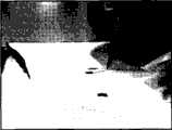
图1(a)表示本发明实施例之一,为表示CNT绳的照片。 Fig. 1(a) shows one of the examples of the present invention, and is a photograph showing a CNT rope. the
图1(b)表示本发明实施例之一,为表示CNT绳的照片。 Fig. 1(b) shows one of the examples of the present invention, and is a photograph showing a CNT rope. the
图2表示本发明实施例之一,为表示制作刷状CNT的装置的示意结构的剖面图。 Fig. 2 is a cross-sectional view showing a schematic structure of an apparatus for producing brush-shaped CNTs, which is one of the embodiments of the present invention. the
图3表示本发明实施例之一,为表示制作刷状CNT的工序的方框图。 Fig. 3 is a block diagram showing a process of producing brush-shaped CNTs, which is one of the embodiments of the present invention. the
图4表示本发明实施例之一,为载气与原料气体的流量关系图。 Fig. 4 shows one of the embodiments of the present invention, which is a flow relationship diagram of carrier gas and raw material gas. the
图5表示本发明实施例之一,为原料气体浓度与成长速度的关系图。 Fig. 5 shows one of the embodiments of the present invention, which is a graph showing the relationship between the raw material gas concentration and the growth rate. the
图6(a)表示本发明实施例之一,为表示刷状CNT的扫描型电子显微镜(SEM)图像的照片。 Fig. 6(a) shows one of the examples of the present invention, and is a photograph showing a scanning electron microscope (SEM) image of brush-shaped CNTs. the
图6(b)表示本发明实施例之一,为表示刷状CNT的扫描型电子显微镜(SEM)图像的照片。 Fig. 6(b) shows one of the examples of the present invention, and is a photograph showing a scanning electron microscope (SEM) image of a brush-like CNT. the
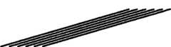
图7(a)表示本发明实施例之一,为表示CNT绳的照片。 Fig. 7(a) shows one of the examples of the present invention, and is a photograph showing a CNT rope. the
图7(b)表示本发明实施例之一,为表示CNT绳的照片。 Fig. 7(b) shows one of the examples of the present invention, and is a photograph showing a CNT rope. the
图8表示本发明实施例之一,(a)~(d)为表示CNT绳的扫描型电子显微镜(SEM)图像的照片。Fig. 8 shows an example of the present invention, and (a) to (d) are photographs showing scanning electron microscope (SEM) images of CNT ropes.
图9表示本发明实施例之一,为表示CNT薄片的照片。 Fig. 9 shows one of the examples of the present invention, and is a photograph showing a CNT flake. the
图10(a)表示本发明实施例之一,为表示刷状CNT的扫描型电子显微镜(SEM)图像的照片。 Fig. 10(a) shows an example of the present invention, and is a photograph showing a scanning electron microscope (SEM) image of a brush-like CNT. the
图10(b)表示本发明实施例之一,为表示刷状CNT的扫描型电子显微镜(SEM)图像的照片。 Fig. 10(b) shows an example of the present invention, and is a photograph showing a scanning electron microscope (SEM) image of a brush-like CNT. the
图10(c)表示本发明实施例之一,为表示CNT绳的扫描型电子显微镜(SEM)图像的照片。 Fig. 10(c) shows an example of the present invention, and is a photograph showing a scanning electron microscope (SEM) image of a CNT rope. the
图10(d)表示本发明实施例之一,为表示CNT绳的扫描型电子显微镜(SEM)图像的照片。 Fig. 10(d) shows an example of the present invention, and is a photograph showing a scanning electron microscope (SEM) image of a CNT rope. the
图11(a)表示本发明实施例之一,为举起CNT绳时的照片。 Fig. 11(a) shows one of the embodiments of the present invention, and it is a photograph when a CNT rope is lifted. the
图11(b)表示本发明实施例之一,为举起CNT绳时的照片。 Fig. 11(b) shows one of the embodiments of the present invention, and it is a photograph when a CNT rope is lifted. the
图12表示本发明实施例之一,为表示用来测定电特性的样品的照片。 Fig. 12, which shows one of the examples of the present invention, is a photograph showing a sample used for measuring electrical characteristics. the
图13(a)表示本发明实施例之一,为表示制造层压材料及层压体的工序的示意图。 Fig. 13(a) shows one of the embodiments of the present invention, and is a schematic view showing the steps of manufacturing a laminated material and a laminated body. the
图13(b)表示本发明实施例之一,为表示制造层压材料及层压体的工序的示意图。 Fig. 13(b) shows one of the embodiments of the present invention, and is a schematic view showing the steps of manufacturing a laminated material and a laminated body. the
图13(c)表示本发明实施例之一,为表示制造层压材料及层压体的工序的示意图。 Fig. 13(c) shows one of the embodiments of the present invention, and is a schematic diagram showing the steps of manufacturing a laminated material and a laminated body. the
图14表示本发明实施例之一,为表示缠绕CNT绳的线圈状结构物的照片。 Fig. 14 shows one of the examples of the present invention, and is a photograph showing a coiled structure wound with a CNT string. the
图15(a)表示本发明实施例之一,为表示刷状CNT的扫描型电子显微镜(SEM)图像的照片。 Fig. 15(a) shows an example of the present invention, and is a photograph showing a scanning electron microscope (SEM) image of a brush-like CNT. the
图15(b)为表示现有的刷状CNT的扫描型电子显微镜(SEM)图像的照片。 Fig. 15(b) is a photograph showing a scanning electron microscope (SEM) image of a conventional brush-like CNT. the
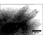
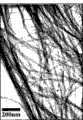
图16(a)表示本发明实施例之一,为表示刷状CNT的透过型电子显微镜(TEM)图像的照片。 Fig. 16(a) shows an example of the present invention, and is a photograph showing a transmission electron microscope (TEM) image of a brush-like CNT. the
图16(b)表示本发明实施例之一,为表示刷状CNT的透过型电子显微镜(TEM)图像的照片。Fig. 16(b) shows an example of the present invention, and is a photograph showing a transmission electron microscope (TEM) image of a brush-like CNT.
图17(a)表示本发明实施例之一,为表示测定CNT绳强度时的状态的照片。 Fig. 17(a) shows one of the examples of the present invention, and is a photograph showing the state when the strength of the CNT rope was measured. the
图17(b)表示本发明实施例之一,为表示测定CNT绳强度时的状态的照片。 Fig. 17(b) shows one of the examples of the present invention, and is a photograph showing the state when the strength of the CNT rope was measured. the
图17(c)为表示测定现有的CNT绳强度时的状态的照片。 Fig. 17(c) is a photograph showing the state when the strength of a conventional CNT rope was measured. the
图17(d)为表示测定现有的CNT绳强度时的状态的照片。 Fig. 17(d) is a photograph showing the state when the strength of a conventional CNT rope was measured. the
图18表示本发明实施例之一,为表示刷状CNT的CNT密度与CNT绳的长度的关系的曲线图。 Fig. 18 is a graph showing the relationship between the CNT density of brush-like CNTs and the length of CNT ropes, which shows one of the examples of the present invention. the
具体实施方式Detailed ways
下面将说明本发明的实施方式。但本发明并不局限于此。 Embodiments of the present invention will be described below. However, the present invention is not limited thereto. the
本发明是多个碳类精细结构物聚集的碳类精细结构物聚集物(以下称为“聚集物”),该多个碳类精细结构物以相同的方向取向的同时,沿着取向方向聚集。本发明的聚集物另包括碳类精细结构物在相对取向方向垂直的方向上聚集的聚集物。这些聚集物是通过在基板上形成在相对该基板大约垂直的方向上取向的多个碳类精细结构物,拉伸至少一个碳类精细结构物而制成。下面将具体说明。 The present invention is a carbon-based fine structure aggregate (hereinafter referred to as "aggregate") in which a plurality of carbon-based fine structures aggregates along the orientation direction while being oriented in the same direction . The aggregates of the present invention also include aggregates in which carbon-based fine structures are aggregated in a direction perpendicular to the orientation direction. These aggregates are formed by forming a plurality of carbon-based fine structures oriented in a direction approximately perpendicular to the substrate on a substrate, and stretching at least one carbon-based fine structure. It will be described in detail below. the
[碳类精细结构物] [Carbon fine structure]
碳类精细结构物是以碳原子构成的纳米尺寸的物质,是以通过碳原子相互结合而生成的网目结构作为基本骨架的纳米级结构物。更详细说明,碳类精细结构物是由石墨型键构成的骨架具有3维结构的物质。3维结构优选是筒状。 The carbon-based fine structure is a nano-sized substance composed of carbon atoms, and a nano-scale structure with a network structure formed by combining carbon atoms with each other as a basic skeleton. More specifically, the carbon-based fine structure is a substance having a three-dimensional structure with a skeleton composed of graphite-type bonds. The three-dimensional structure is preferably cylindrical. the
碳类精细结构物具体有,如碳纳米管(以下称为CNT)。另外,CNT上形成微珠的附微珠CNT、CNT有螺旋的碳纳米螺旋(Carbon NanoTwist)、线圈状的碳纳米线圈(Carbon Nano Coil)、球壳状的富勒烯(fullerene)等也包含于碳类精细结构物。而且,也会将多个上述碳类精细结构物的CNT林立而成的、所谓的刷状CNT称之为碳类精细结构物群。Specific examples of carbon-based fine structures include carbon nanotubes (hereinafter referred to as CNTs). In addition, bead-attached CNT with microbeads formed on CNT, carbon nanotwist with helix in CNT, carbon nanocoil in coil shape, fullerene in spherical shell shape, etc. in carbon fine structures. In addition, so-called brush-like CNTs in which a plurality of CNTs of the above-mentioned carbon-based fine structures stand in a row are called carbon-based fine-structure groups.
如后所述,本发明的聚集物是使用刷状CNT制造的。因此在以下,作为碳类精细结构物将例举CNT,作为碳类精细结构物群将例举刷状CNT,来进行说明。 As will be described later, the aggregates of the present invention are produced using brush-like CNTs. Therefore, in the following description, CNTs will be exemplified as carbon-based fine structures, and brush-like CNTs will be exemplified as carbon-based fine structures. the
[碳类精细结构物群] [Carbon fine structure group]
刷状CNT是在基板上使在对基板大约垂直的方向上取向的多个CNT林立而成的。作为基板可以使用在Si晶片上作为催化剂形成Fe薄膜的物质。另外,大约垂直的方向是指几乎垂直的方向,虽然完全垂直的方向较好,但也包括从基板离去的方向。 The brush-like CNTs are formed by arranging a plurality of CNTs aligned in a direction approximately perpendicular to the substrate on a substrate. As the substrate, what is used as a catalyst to form an Fe thin film on a Si wafer can be used. In addition, the substantially vertical direction refers to a substantially vertical direction, and although a completely vertical direction is preferable, it also includes a direction away from the substrate. the
本发明的刷状CNT优选是在基板上形成的CNT的长度(从基板的高度)具有一定长度(高度),并且多个CNT以高密度形成。在制作聚集物时,通过基板上形成的CNT具有一定长度,能够获取更长的聚集物。具体是,作为刷状CNT形成的CNT的长度优选是数μm以上。 The brush-like CNTs of the present invention preferably have a certain length (height) of CNTs formed on the substrate (height from the substrate), and a plurality of CNTs are formed at a high density. When forming aggregates, the CNTs formed on the substrate have a certain length, and longer aggregates can be obtained. Specifically, the length of CNTs formed as brush-like CNTs is preferably several μm or more. the
另外,通过以高密度形成多个CNT,在邻接的CNT之间生成范德华力等较强的互作用,而使聚集物制造变得较容易。此类刷状CNT优选是,如在基板的1μm四周内形成有10个以上的CNT的刷状CNT。即,CNT密度优选为10个/1μm2以上(1×109个/cm2以上)。 In addition, by forming a plurality of CNTs at a high density, a strong interaction such as van der Waals force is generated between adjacent CNTs, thereby facilitating production of aggregates. Such brush-like CNTs are preferably, for example, brush-like CNTs in which 10 or more CNTs are formed within 1 μm of the substrate. That is, the CNT density is preferably 10/1 μm2 or more (1×10⁹ /cm2 or more).
如上所述,本发明的聚集物是使用刷状CNT形成。在后面将详细说明,刷状CNT的CNT密度越高越能形成长的聚集物。所以,刷状CNT的CNT密度优选为1×10¹⁰本/cm2以上,更优选为1×1011本/cm2以上。 As noted above, the aggregates of the present invention are formed using brush-like CNTs. As will be described in detail later, the higher the CNT density of the brush-like CNTs, the longer the aggregates can be formed. Therefore, the CNT density of the brush-like CNTs is preferably 1×10¹⁰ cells/cm2 or more, more preferably 1×10¹¹ cells/cm2 or more.
另外,刷状CNT的CNT优选为具有更高的结晶性的CNT。结晶性越高CNT越呈直线,CNT越呈直线,聚集物的制作越变得容易。即,理想的CNT为直线状的CNT,当CNT的结晶构造有缺陷时,会形成弯曲的CNT,因此不好。 In addition, the CNT of the brush CNT is preferably a CNT having higher crystallinity. The higher the crystallinity, the more linear the CNT is, and the more linear the CNT is, the easier it is to produce aggregates. That is, ideal CNTs are linear CNTs, but if the crystal structure of CNTs is defective, curved CNTs will be formed, which is not preferable. the
在此,所谓的缺陷是指在构成CNT的有规则结晶序列中存在无规则的结晶序列时的该无规则的结晶序列部分。CNT是由碳原子的六杂环连接(六角板状结晶)的石墨烯片构成,当存在六杂环以外的如五杂环或七杂环时该部分为缺陷部分。Here, the term "defect" refers to a part of the random crystal sequence when there is a random crystal sequence in the regular crystal sequence constituting CNT. CNT is composed of graphene sheets connected by hexaheterocycles of carbon atoms (hexagonal plate crystals). When there are pentaheterocycles or heptaheterocycles other than hexaheterocycles, this part is a defective part.
当六杂环有规则地连接时CNT成直线。而在CNT中,当一部分中含有五杂环或七杂环时,该部分(缺陷部分)中的结晶性降低而弯曲。因此为了提高CNT的直线性,优选是做成缺陷部分少的CNT。缺陷部分少的CNT例如有在长度1μm的部分中存在的欠缺部分为10以下的CNT。 The CNTs line up when the hexaheterocycles are regularly linked. On the other hand, in a CNT, when a part contains a pentaheterocycle or a heptaheterocycle, the crystallinity of the part (defect part) decreases and the CNT bends. Therefore, in order to improve the linearity of CNTs, it is preferable to use CNTs with few defective parts. CNTs with few defective parts include, for example, CNTs having 10 or less defective parts in a part with a length of 1 μm. the
另外,当CNT的结晶中含有无定形碳(Amorphous)或CNT的周围形成有无定形碳的层时,也会导致CNT结晶性的劣化。因此,越是少含无定形碳的CNT,结晶性越高。 In addition, when amorphous carbon (Amorphous) is contained in the CNT crystal or a layer of amorphous carbon is formed around the CNT, the crystallinity of the CNT is also degraded. Therefore, the less amorphous carbon CNT contains, the higher the crystallinity. the
在此,图15(a)为表示本发明的CNT的SEM图像的照片。图15(b)为表示现有的CNT的SEM图像的照片。如15(a)及图15(b)所示,本发明的CNT中,存在于CNT周围的无定形碳非常少。而在现有的CNT中,存在于CNT周围的无定形碳非常多。因此,相对现有的CNT为石墨片无规则弯曲的、低直线性CNT的情况,本发明的CNT是,石墨片呈非常利绳的层状构造的,且具有非常高的直线性的CNT。 Here, Fig. 15(a) is a photograph showing a SEM image of CNTs of the present invention. Fig. 15(b) is a photograph showing a SEM image of a conventional CNT. As shown in Fig. 15(a) and Fig. 15(b), in the CNT of the present invention, there is very little amorphous carbon present around the CNT. On the other hand, in existing CNTs, there is a lot of amorphous carbon around the CNTs. Therefore, the CNT of the present invention has a very straight layered structure of graphite sheets and has very high linearity, compared to conventional CNTs in which graphite sheets are randomly bent and low linearity. the
CNT的周围形成的无定形碳层的厚度优选为,CNT直径的10%以下。此时能够制成具有更高的直线性的CNT。 The thickness of the amorphous carbon layer formed around the CNT is preferably 10% or less of the diameter of the CNT. In this case, CNTs having higher linearity can be produced. the
如上所述地结晶性高的CNT形成直线性高的CNT。CNT的直线性高则CNT之间的相互作用变强,因此,通过使用含此类高结晶性的CNT的刷状CNT,能够很容易地制作高强度的聚集物。其中,可用后述本发明的制造方法制造高结晶性的直线性CNT。 As described above, CNTs with high crystallinity form CNTs with high linearity. When the linearity of CNTs is high, the interaction between CNTs becomes strong. Therefore, by using brush-like CNTs containing such highly crystalline CNTs, it is possible to easily produce high-strength aggregates. Among them, highly crystalline linear CNTs can be produced by the production method of the present invention described later. the
另外,上述CNT优选是,石墨片层数为2层以上20层以下。石墨片的层数增多时,能够提高而后生成的聚集物的强度。另一方面,石墨片的层数超出20时,反而使聚集物没有柔软性,当负载一定的力时有折断的可能性。 In addition, the above-mentioned CNT preferably has a graphite sheet number of 2 or more and 20 or less layers. When the number of layers of graphite flakes increases, the strength of aggregates generated subsequently can be increased. On the other hand, if the number of layers of graphite sheets exceeds 20, the aggregates will not be flexible and may break when a certain force is applied. the
[碳类精细结构物群的制造方法] [Manufacturing method of carbon-based fine structure group]
本发明的刷状CNT可通过催化剂化学气相沉积法(CCVD法:CatalystChemical Vapor Deposition)制造。CCVD法是在反应室中配置催化剂,向反应室内提供载气以及原料气体,在该催化剂的表面生长CNT的方法。下面将说明使用CCVD法生长CNT,制造刷状CNT的方法。 The brush-like CNT of the present invention can be produced by a catalyst chemical vapor deposition method (CCVD method: Catalyst Chemical Vapor Deposition). The CCVD method is a method of arranging a catalyst in a reaction chamber, supplying a carrier gas and a source gas into the reaction chamber, and growing CNTs on the surface of the catalyst. Next, a method of growing CNTs using the CCVD method to produce brush-shaped CNTs will be described. the
图2为表示制作刷状CNT的装置1的示意结构的附图。如图2所示,在反应室2内配置有催化剂体3。催化剂体3为在表面形成了催化剂的基体,该基体的形状有基板、多层基板、筒状体、多面体、颗粒、粉状体等各种形态。另外,所使用的催化剂例如可使用铁、钴、镍、铁合金、钴合金、镍合金、铁氧化物、钴氧化物、镍氧化物、和这些的组合物等各种的已知催化剂。 FIG. 2 is a diagram showing a schematic configuration of an
接着,向反应室2提供载气及原料气体。图3为表示将载气及原料气体向反应室2提供的工序图。载气被容纳于第1容器4以及第2容器5中。第1容器4内的载气被由质量流量控制器构成的第1流量控制器6调节至基本流量后向反应室2供给。另外,第2容器5内的载气被由质量流量控制器构成的第2流量控制器7调节至规定流量后,通过电磁式三向阀8向反应室2供给。 Next, a carrier gas and a source gas are supplied to the
作为载气可使用He、Ne、Ar、N2、H2等的气体。载气是为搬送原料气体的气体,原料气体通过反应被消耗,而载气没有任何反应而不被消耗。 Gases such as He, Ne, Ar, N2 , and H2 can be used as the carrier gas. The carrier gas is used to transport the raw material gas. The raw material gas is consumed through the reaction, while the carrier gas is not consumed without any reaction.
原料气体被收容与第3容器9中。第3容器9中的原料气体被由质量流量控制器构成的第3流量控制器10调节至规定流量后,通过电磁式三向阀11向反应室供给。 The source gas is accommodated in the
作为原料气体可使用碳化氢、含硫黄有机气体、含磷有机气体等的有机气体。可根据所生成的CNT结构适当选择原料气体。这些气体中,出于不生成多余的物质的观点而优选碳化氢。 Organic gases such as hydrocarbons, sulfur-containing organic gases, and phosphorus-containing organic gases can be used as the source gas. The source gas can be appropriately selected according to the structure of the CNT to be produced. Among these gases, hydrocarbon is preferable from the viewpoint of not generating unnecessary substances. the
作为上述碳化氢,可使用,甲烷、乙烷等的烷化合物;乙烯、丁二烯等的烯化合物;乙炔等的炔烃化合物;苯、甲苯、苯乙烯等的芳基碳氢化合物;茚、萘、菲等含缩合环的芳香族碳氢化合物;环丙烷、环己烷等的环链烷烃化合物;环戊烯等的环烯化合物;类固醇等的有缩合环的脂环类碳氢化合物等。另外,可使用混合了2种以上的上述碳氢化合物的混合碳化氢气体。上述碳氢化合物中,优选使用乙炔、丙炔、乙烯、苯、甲苯。 As the hydrocarbons mentioned above, alkane compounds such as methane and ethane; alkene compounds such as ethylene and butadiene; alkyne compounds such as acetylene; aryl hydrocarbon compounds such as benzene, toluene and styrene; Aromatic hydrocarbons containing condensed rings such as naphthalene and phenanthrene; cycloalkane compounds such as cyclopropane and cyclohexane; cycloalkenes such as cyclopentene; alicyclic hydrocarbons such as steroids with condensed rings, etc. . In addition, a mixed hydrocarbon gas in which two or more of the above-mentioned hydrocarbons are mixed can be used. Among the above-mentioned hydrocarbons, acetylene, propyne, ethylene, benzene, and toluene are preferably used. the
上述电磁式三向阀8、11可通过自动阀控制器的作用而可控制在断开状态和供给状态的两个方向,即,载气和原料气体,在断开状态下通过补助排气管被排气,在供给状态下被供给于反应室。电磁式三向阀8呈供给 状态时,电磁式三向阀11呈断开状态。另一方面,当电磁式三向阀8呈断开状态时,电磁式三向阀11呈供给状态。 The above-mentioned electromagnetic three-
另外,这些电磁式三向阀8、11具有0.1s以下的应答时间。并且,从第1容器4向反应室2供给的载气的流量总是被控制在基本流量的程度,同时从第2容器5向反应室2供给的载气的流量以及从第3容器9向反应室2供给的原料气体的流量总是被控制成相同的流量。因此,断开状态和供给状态的更换在瞬间被完成,向反应室2总是供给有一定量的气体。 In addition, these electromagnetic three-
如从第1容器4供给的载气的基本流量设为X(cm3/s(常规的)),从第2容器5供给的载气的流量以及从第3容器9供给的原料气体的流量设为Y(cm3/s(常规的))。 If the basic flow rate of the carrier gas supplied from the
如图4所示,从第1容器4供给的载气一直以X(cm3/s(常规的))的流量向反应器2供给。另外,在不制造刷状CNT时,电磁式三向阀8呈供给状态,电磁式三向阀11呈断开状态。因此,从第2容器5以Y(cm3/s(常规的))的流量供给载气。此时,向反应室2以X+Y(cm3/s(常规的))的流量供给气体。 As shown in FIG. 4 , the carrier gas supplied from the
另一方面,在制造刷状CNT时,电磁式三向阀8呈断开状态,电磁式三向阀11呈供给状态。因此,从第3容器9以Y(cm3/s(常规的))的流量供给原料气体。此时,向反应室2也以X+Y(cm3/s(常规的))的流量供给气体。即,向反应室2一直有一定量的气体被供给。 On the other hand, when producing brush-shaped CNTs, the electromagnetic three-
另外,将反应室2加热至CNT最容易生长的温度区域,原料气体在催化剂3的附近被热分解。进而分解物从催化剂3的表面,作为CNT生长。 In addition, the
接着,对使用上述装置1来制造刷状CNT的方法进行具体说明。作为催化剂体(基板)3,使用在表面形成有4nm的铁催化剂膜的Si基板。作为载气,使用He气;作为原料气体,使用C2H2气。将第1容器4的He气的基本流量设成0.93cm3/s(常规的),第2容器5的He气及第3容器9的C2H2气的规定流量设成3.11cm3/s(常规的)。 Next, a method for producing brush-shaped CNTs using the above-mentioned
首先,将上述基板3设置在反应室2的中央。进而将反应室2加热至700℃。此时,电磁式三向阀8呈供给状态,向反应室2内供给4.04cm3/s(常 规的)的He气。其后将电磁式三向阀8改成切断状态,同时将电磁式三向阀11改成供给状态。通过如此,向反应室2内供给3.11cm3/s(常规的)的C2H2气和0.93cm3/s(常规的)的He气。即,此时的C2H2气的浓度为76.9%。另将C2H2气的供给时间设成0.8秒。供给C2H2气后,在气体通过反应室2的5分钟后进行降温。通过这样,C2H2中的碳原子在基板3上生长、制作成刷状CNT。 First, the above-mentioned
在此,参照图5,说明制造刷状CNT时的CNT生长速度与原料气体浓度的关系。如图5所示,随着原料气体浓度的上升,CNT的生长速度增加。这可能是因为原料气体到达基板时,原料气体的浓度变化变得更为急剧。因为CNT的生长速度很快而能够缩短制作时间,同时能够形成长的CNT。 Here, referring to FIG. 5 , the relationship between the CNT growth rate and the raw material gas concentration when producing brush-like CNTs will be described. As shown in Fig. 5, the growth rate of CNTs increases as the concentration of the source gas increases. This is probably because the concentration of the source gas changes more rapidly when the source gas reaches the substrate. Since the growth rate of CNT is fast, the production time can be shortened, and at the same time, long CNT can be formed. the
一方面,将原料气体浓度从23%上升到76.9%时,CNT的密度变到2×10¹⁰个/cm2~7×1011个/cm2。所以能够确定,原料气体的浓度越高越能形成高密度的CNT。 On the other hand, when the source gas concentration is increased from 23% to 76.9%, the density of CNTs becomes 2×10¹⁰ /cm2 to 7×10¹¹ /cm2 . Therefore, it can be confirmed that the higher the concentration of the raw material gas, the higher the density of CNTs can be formed.
因此,制造刷状CNT时,原料气体的浓度优选是数十%以上。具体为23%以上,优选70%以上。此时,能够使CNT生长地很长,同时能够以高密度形成。 Therefore, when producing brush-like CNTs, the concentration of the raw material gas is preferably several tens% or more. Specifically, it is 23% or more, preferably 70% or more. In this case, the CNTs can be grown very long and can be formed at a high density. the
另外,将原料气体供给时间延长时,能够延长CNT的生长时间。因此,通过控制原料气体供给时间而可以形成更长的CNT。但是,此时CNT的直径也变粗。所以,原料气体的供给时间可根据原料气体的浓度、或CNT的长度及粗细程度而适当设定,优选0.001秒~60秒的范围内。 In addition, when the source gas supply time is extended, the CNT growth time can be extended. Therefore, longer CNTs can be formed by controlling the source gas supply time. However, at this time, the diameter of the CNT also becomes thicker. Therefore, the supply time of the source gas can be appropriately set according to the concentration of the source gas, or the length and thickness of the CNTs, and is preferably in the range of 0.001 seconds to 60 seconds. the
在图6(a)及图6(b)为表示了所制作的刷状CNT的扫描型电子显微镜(SEM)图像的照片。图6(b)为图6(a)的放大图像。如图6(a)及图6(b)所示,刷状CNT的各CNT的直线性极高,生长到长度为170μm的程度。另可推测到CNT密度至少是1×10¹⁰个/cm2以上。 FIG. 6( a ) and FIG. 6( b ) are photographs showing scanning electron microscope (SEM) images of the produced brush-like CNTs. Figure 6(b) is an enlarged image of Figure 6(a). As shown in FIG. 6( a ) and FIG. 6( b ), each CNT of the brush-like CNT has extremely high linearity and grows to a length of about 170 μm. It is also estimated that the CNT density is at least 1×10¹⁰ /cm2 or more.
在本实施方式中,上述CNT密度的测定是通过观察SEM图像及TEM图像,以如下的方法进行测定。 In the present embodiment, the measurement of the above-mentioned CNT density is performed by the following method by observing the SEM image and the TEM image. the
首先,着眼于如图6(a)及图6(b)所示的、刷状CNT的SEM图像中的相同对比度部分的CNT。在此,相同对比度部分是指在SEM图像中显 示的CNT浓度几乎一定的部分。该部分是被推测为CNT密度几乎一定的部分。 First, attention is paid to the CNTs in the same contrast portion in the SEM image of the brush-like CNTs as shown in FIG. 6( a ) and FIG. 6( b ). Here, the same-contrast portion refers to a portion where the CNT concentration shown in the SEM image is almost constant. This portion is estimated to have a substantially constant CNT density. the
进而,测定上述相同对比度部分的CNT的宽度。通过如此,能够推测到相同对比度部分的CNT的直径。接着测定该部分中存在的CNT的个数。由此能够推测到相同对比度部分中的CNT密度。其中,在SEM图像中观察到的CNT为多个CNT成束状态的CNT。因此,在SEM图像中推测的密度表示了在单位面积中存在的束状CNT的个数。 Furthermore, the width of the CNT in the above-mentioned same-contrast portion was measured. In this way, the diameter of the CNT in the same contrast portion can be estimated. Next, the number of CNTs present in this portion was measured. From this, the CNT density in the same contrast portion can be estimated. Among them, the CNTs observed in the SEM image are CNTs in a bundled state of a plurality of CNTs. Therefore, the density estimated in the SEM image indicates the number of bundle-like CNTs present per unit area. the
接着,在TEM图像中观察已推测了上述直径以及密度的部分的CNT。图16(a)及图16(b)是表示上述CNT的TEM图像的照片。在该TEM图像中,能够观察上述SEM图像中观察到的束状CNT中的成束的各CNT。因此通过观察TEM图像,能够测定在上述SEM图像中作为1个被观察的束状CNT所含的CNT个数。 Next, the CNTs of the part where the above-mentioned diameter and density were estimated were observed in a TEM image. Fig. 16(a) and Fig. 16(b) are photographs showing TEM images of the above CNTs. In this TEM image, each CNT bundled among the bundled CNTs observed in the above-mentioned SEM image can be observed. Therefore, by observing the TEM image, it is possible to measure the number of CNTs contained in one bundle-shaped CNT observed in the SEM image. the
在上述SEM图像的观察中,已测定了相同对比度部分的CNT的直径和存在于该部分的束状CNT的个数,所以通过利用TEM图像的观察来测定束状CNT所含的CNT的个数,而可以测定存在于单位面积的CNT个数。即,能够测定CNT的密度。 In the observation of the above SEM image, the diameter of the CNT in the same contrast portion and the number of bundle-shaped CNTs present in the portion have been measured, so the number of CNTs contained in the bundle-shaped CNT is measured by observation using the TEM image , and the number of CNTs present in a unit area can be measured. That is, the density of CNTs can be measured. the
另外,通过使用本发明的制造方法,在可以制造上述具有高结晶性的CNT的同时,可以制造由高结晶性的CNT构成的刷状CNT。 In addition, by using the production method of the present invention, it is possible to produce brush-shaped CNTs composed of highly crystalline CNTs while producing the above-mentioned CNTs having high crystallinity. the
[碳类精细结构物聚集物] [Carbon fine structure aggregates]
下面说明本发明的碳类精细结构物的聚集物。本发明的聚集物是多个CNT以相同方向取向的同时,沿着该取向方向聚集的聚集物。在此,所谓“以相同方向取向”是指全部碳类精细结构物以各长度方向呈相同方向的样子聚集。其中,碳类精细结构物可不具有直线构造,呈多少有弯曲状态的情况较多,长度方向只要是连接其两端部的方向即可,是指碳类精细结构物的实质的方向。 The aggregate of the carbon-based fine structure of the present invention will be described below. The aggregate of the present invention is an aggregate in which a plurality of CNTs are aligned in the same direction and aggregated along the orientation direction. Here, "orientation in the same direction" means that all the carbon-based fine structures are aggregated so that the longitudinal directions are in the same direction. Among them, the carbon-based fine structure does not need to have a linear structure, and it is often in a somewhat curved state. The longitudinal direction is only a direction that connects its two ends, and refers to the substantial direction of the carbon-based fine structure. the
另外,本发明的聚集物呈多个CNT相互络合的束状。所以,本发明的聚集物具有以相同方向取向的多个CNT成束状,并且向长度方向延伸的结构。下面,为了容易说明,将具有该结构的聚集物称为“CNT绳”。In addition, the aggregate of the present invention is in the form of a bundle in which a plurality of CNTs are complexed with each other. Therefore, the aggregate of the present invention has a structure in which a plurality of CNTs oriented in the same direction are bundled and extend in the longitudinal direction. Hereinafter, aggregates having this structure are referred to as "CNT ropes" for ease of description.
而且,本发明的聚集物还包括,以上述取向方向的直角方向聚集的聚集物。所谓取向方向的直角方向是指,相对所谓CNT绳的长度方向的直角方向(宽度方向)。进而,此时,取向于长度方向的CNT绳还具有在宽度方向上聚集的结构,成为具有平面扩散的聚集物。该结构也可以进一步表示为CNT绳在周边方向上聚集的结构。为了容易说明,下面将具有该结构的聚集物称之为“CNT薄片”。 Furthermore, the aggregates of the present invention also include aggregates aggregated in a direction perpendicular to the orientation direction described above. The direction perpendicular to the orientation direction refers to the direction perpendicular to the longitudinal direction (width direction) of the so-called CNT rope. Furthermore, at this time, the CNT ropes oriented in the longitudinal direction also have a structure aggregated in the width direction, and become aggregates having planar diffusion. This structure can also be further expressed as a structure in which CNT ropes gather in the peripheral direction. For ease of description, aggregates having this structure will be referred to as "CNT flakes" below. the
图1(a)、图1(b)以及图7(a)、图7(b)表示本发明的CNT绳。图1(a)、图1(b)是长度约为20cm程度的CNT绳,7(a)、图7(b)是长度约为30cm程度的CNT绳。如这些图所示,本发明的CNT绳是用肉眼就能充分进行确认的系状物质。 Fig. 1(a), Fig. 1(b) and Fig. 7(a), Fig. 7(b) show the CNT rope of the present invention. Fig. 1(a) and Fig. 1(b) are CNT ropes with a length of about 20 cm, and Fig. 7(a) and Fig. 7(b) are CNT ropes with a length of about 30 cm. As shown in these figures, the CNT rope of the present invention is a string-like substance that can be fully confirmed with the naked eye. the
下面将说明CNT绳的详细构成。图8为图1(a)、图1(b)所示的CNT绳的SEM图像。图8的(b)及(c)为扩大图8(a)所示的CNT绳一部分的SEM图像。图8的(d)为扩大图8(c)所示的CNT绳一部分的SEM图像。 The detailed constitution of the CNT rope will be described below. Fig. 8 is a SEM image of the CNT rope shown in Fig. 1(a) and Fig. 1(b). (b) and (c) of FIG. 8 are enlarged SEM images of a part of the CNT rope shown in FIG. 8( a ). FIG. 8( d ) is an enlarged SEM image of a part of the CNT rope shown in FIG. 8( c ). the
如图8所示,CNT绳由多个CNT成束而成。即,各个CNT结成束而形成。该CNT绳的平均直径约为50μm的程度。另外,构成CNT绳的1个纤维状结构物的直径约为50nm。相对于此,到目前为止在透过型电子显微镜(TEM)所观察到的刷状CNT中的各个CNT的直径为10nm~20nm的程度。所以可以确定CNT绳是由各个CNT结成束而形成。 As shown in Figure 8, the CNT rope is made of multiple CNTs bundled together. That is, individual CNTs are formed in bundles. The average diameter of the CNT rope is about 50 μm. In addition, the diameter of one fibrous structure constituting the CNT rope is about 50 nm. In contrast, the diameter of each CNT in the brush-like CNTs observed with a transmission electron microscope (TEM) is about 10 nm to 20 nm. Therefore, it can be determined that the CNT rope is formed by the bundles of individual CNTs. the
相对刷状CNT中的各个CNT的平均长度为,数十μm的程度,本发明的CNT绳的长度可达到20cm或30cm,通过控制刷状CNT中的CNT密度而可以制作50cm以上长度的CNT绳。这是由于,各个CNT以相同方向取向的同时向长度方向连续地结成束的原因。即,本发明的CNT绳具有各个CNT结成束的同时以相同方向取向的结构。 The average length of each CNT in the brush-like CNT is about several tens of μm, and the length of the CNT rope of the present invention can reach 20 cm or 30 cm. By controlling the CNT density in the brush-like CNT, it is possible to produce a CNT rope with a length of 50 cm or more . This is because each CNT is oriented in the same direction and is continuously bundled in the longitudinal direction. That is, the CNT rope of the present invention has a structure in which individual CNTs are bundled and oriented in the same direction. the
结成束的CNT绳中有通过范德华力而相互结合的部分。由此,CNT通过强的相互作用而相结合。因此,CNT绳具有高强度。如果进一步对结成束的CNT进行物理性或化学的结合,那么将可以制成具有更高强度的CNT绳。Some of the bundled CNT ropes are bonded to each other by van der Waals force. Thus, CNTs are bound by strong interactions. Therefore, the CNT rope has high strength. If the bundled CNTs are further physically or chemically bonded, CNT ropes with higher strength can be produced.
另外,CNT薄片是上述CNT绳在平面聚集而成的。即,CNT绳成片状的物质。进而,CNT薄片通过各个CNT的结成束而形成,但,CNT薄片是各个CNT以相同方向取向的同时向长度方向连续地结成束之外,还向宽度方向结成束。图9表示CNT薄片。图9所示的CNT薄片的宽为4mm,能够确定形成了片状。 In addition, the CNT flakes are formed by gathering the above-mentioned CNT ropes in a plane. That is, CNTs are a sheet-like substance. Furthermore, the CNT flakes are formed by bundles of individual CNTs, but the CNT flakes are not only continuously bundled in the longitudinal direction but also bundled in the width direction while each CNT is oriented in the same direction. Figure 9 shows CNT flakes. The width of the CNT flakes shown in FIG. 9 was 4 mm, and it was confirmed that the flakes were formed. the
本发明的CNT绳因使用含高结晶性的CNT的刷状CNT制作,所以是高结晶性的CNT绳。即,能够制成高直线性的CNT绳。并且,因上述刷状CNT的CNT以高密度形成,所以能够制作长CNT绳的同时,可制造高强度的CNT绳。 The CNT rope of the present invention is a highly crystalline CNT rope because it is produced using brush-like CNTs containing highly crystalline CNTs. That is, a highly linear CNT rope can be produced. In addition, since the CNTs of the above-mentioned brush-like CNTs are formed at a high density, it is possible to manufacture a long CNT rope and at the same time produce a high-strength CNT rope. the
下面说明本发明的CNT绳的强度。图17(a)及图17(b)是表示测定本发明的CNT绳强度时的状态的照片,图17(c)及图17(d)为表示测定现有的CNT绳强度时的状态的照片。图17(a)、图17(b)及图17(c)、图17(d)都表示用共振法测定CNT绳强度(机械强度)时的状态。 The strength of the CNT rope of the present invention will be described below. Fig. 17 (a) and Fig. 17 (b) are photographs showing the state when measuring the strength of the CNT rope of the present invention, and Fig. 17 (c) and Fig. 17 (d) are photographs showing the state when measuring the strength of the conventional CNT rope photo. Fig. 17(a), Fig. 17(b) and Fig. 17(c), Fig. 17(d) all show the state when the strength (mechanical strength) of the CNT rope is measured by the resonance method. the
图17(a)表示静止状态的本发明CNT绳,图17(b)表示振动该CNT绳时的照片。而图17(c)表示静止状态的现有的CNT绳,图17(d)表示振动该CNT绳时的照片。如图17(b)及图17(d)所示,本发明的CNT绳与现有的CNT绳相比,共振幅小,强度高。另外,使用共振法时的杨氏模量(Young′s modulus)是通过下式(1)表示。 Fig. 17(a) shows the CNT rope of the present invention in a static state, and Fig. 17(b) shows a photograph when the CNT rope is vibrated. On the other hand, FIG. 17(c) shows a conventional CNT rope in a static state, and FIG. 17(d) shows a photograph of the CNT rope when it is vibrated. As shown in Fig. 17(b) and Fig. 17(d), the CNT rope of the present invention has smaller resonance amplitude and higher strength than the conventional CNT rope. In addition, the Young's modulus (Young's modulus) when using the resonance method is represented by the following formula (1). the
Y=(64π2ρ/1.8754)×(f02L4/d02)......(1) Y=(64π2 ρ/1.8754 )×(f02 L4 /d02 )...(1)
其中,f0:共振频率、ρ:密度、L:长度、d0:外直径(>>内直径的平方值)。 Wherein, f0 : resonance frequency, ρ: density, L: length, d0 : outer diameter (>>square value of inner diameter).
使用上述式(1)计算杨氏模量的结果,相对现有的CNT绳中为Y=0.1(TPa),本发明的CNT绳中为Y=0.8(TPa)。即,通过机械特性的检查,可发现现有的CNT绳(缺陷多、弯曲大的CNT绳)的杨氏模量小、强度小。 As a result of calculating Young's modulus using the above formula (1), Y=0.8 (TPa) in the CNT rope of the present invention, compared to Y=0.1 (TPa) in the conventional CNT rope. That is, the inspection of the mechanical properties revealed that the existing CNT ropes (CNT ropes with many defects and large bends) had small Young's modulus and low strength. the
[碳类精细结构物聚集物的制造方法] [Method for producing carbon-based fine structure aggregates]
接着,说明本发明的CNT绳的制造方法。可用刷状CNT制造CNT绳。Next, the method for producing the CNT rope of the present invention will be described. CNT ropes can be made from brushed CNTs.
刷状CNT是如上所述地在基板上制作。在制造CNT绳时,首先将劈开该基板。通过如此,在劈开部分的基板上形成的CNT露出。接着,用镊子摘取、拉伸至少一个该露出的CNT。通过如此,邻接的CNT一边连续地相互络合一边被拉出。拉出的方向只要是将CNT从基板拉脱的方向即可。 Brush CNTs were fabricated on substrates as described above. When making CNT ropes, the substrate will first be cleaved. In this way, the CNTs formed on the cleaved portion of the substrate are exposed. Next, use tweezers to pick and stretch at least one exposed CNT. In this way, adjacent CNTs are pulled out while being continuously entangled with each other. The pulling direction may be any direction as long as the CNT is pulled out from the substrate. the
邻接的1个或多个CNT以范德华力结合。通过拉伸其中的至少一个,邻接的CNT成束地被拉伸,进而拉伸被延续。接着,通过继续拉伸,多个CNT成为结成束的CNT绳。 One or more adjacent CNTs are bonded by van der Waals force. By stretching at least one of them, adjacent CNTs are stretched in bundles, and stretching is continued. Then, by continuing stretching, a plurality of CNTs become bundled CNT ropes. the
如上所述,只要通过拉伸相同方向生长的刷状CNT,连续地拉伸CNT,就能够获取各CNT以相同方向取向的CNT绳。所以CNT取向的控制较容易。 As described above, by continuously stretching CNTs by stretching brush-like CNTs grown in the same direction, a CNT rope in which each CNT is oriented in the same direction can be obtained. Therefore, the control of CNT orientation is easier. the
随着CNT绳的制造,刷状CNT如解开毛衣的毛线一样,从基板的端部依次地被剥落。图10(a)表示了制造CNT绳后的刷状CNT的SEM图像。如图10(a)所示,成为CNT被剥落,下面的Si基板露出的状态。 Along with the production of the CNT string, the brush-shaped CNTs were sequentially peeled off from the end of the substrate like unraveling the wool of a sweater. Figure 10(a) shows the SEM image of brush-like CNTs after fabrication of CNT ropes. As shown in FIG. 10( a ), the CNTs are peeled off to expose the underlying Si substrate. the
另外,接近于基板的刷状CNT,如图10(b)所示,CNT相对基板取向于水平方向,成薄片状。在制造CNT绳时,这些CNT结成束,形成1个绳状。图10(c)、图10(d)表示了此时的CNT绳的SEM图像。 In addition, as for the brush-like CNTs close to the substrate, as shown in FIG. 10( b ), the CNTs are oriented in the horizontal direction with respect to the substrate, and form flakes. When producing a CNT rope, these CNTs are bundled to form a single rope. 10(c) and 10(d) show SEM images of the CNT ropes at this time. the
另外,制造CNT薄片时,在从刷状CNT拉伸CNT时,可以增多所拉伸的CNT的个数。如上所述,在接近刷状CNT基板的部分,CNT成薄片状。能够通过将该薄片状CNT就此拉伸而制造CNT薄片。因此,可通过改变拉伸时摘取的CNT个数而适当改变薄片的大小。 In addition, when producing a CNT sheet, when stretching a CNT from a brush-like CNT, the number of stretched CNTs can be increased. As described above, the CNTs are in the form of flakes at the portion close to the brush-like CNT substrate. CNT flakes can be produced by stretching the flaky CNTs as they are. Therefore, the size of flakes can be appropriately changed by changing the number of CNTs extracted during stretching. the
CNT薄片也可以通过拉伸在劈开基板时被劈开而分裂的基板来制造。此时,通过拉伸基板而拉伸在基板上形成的CNT。由此,CNT被连续地解开,可制作成CNT以一个方向排列的CNT薄片。 CNT flakes can also be fabricated by stretching a substrate that is cleaved while cleaving the substrate. At this time, the CNTs formed on the substrate are stretched by stretching the substrate. As a result, CNTs are continuously untied, and CNT flakes in which CNTs are aligned in one direction can be produced. the
并且,可根据刷状CNT中的CNT密度而改变CNT绳或CNT薄片的成束状态。因此,如果可根据CNT绳和CNT薄片的用途等来控制刷状CNT的密度,那么则能够获取成为所希望的束状的CNT绳或CNT薄片。 Also, the bundled state of CNT ropes or CNT flakes can be changed according to the CNT density in the brush-like CNTs. Therefore, if the density of the brush-like CNTs can be controlled according to the usage of the CNT ropes and CNT flakes, etc., it is possible to obtain a desired bundle of CNT ropes or CNT flakes. the
本发明中,因使用了CNT高密度形成的刷状CNT,所以可延长CNT绳或CNT薄片的长度。在此,将对刷状CNT的CNT密度与CNT绳的长 度的关系进行说明。图18为,表示刷状CNT的CNT密度与能够从刷状CNT拉伸出的CNT绳的长度的关系的曲线图。 In the present invention, since brush-like CNTs formed with high CNT density are used, the length of CNT ropes or CNT flakes can be extended. Here, the relationship between the CNT density of the brush-like CNT and the length of the CNT rope will be described. FIG. 18 is a graph showing the relationship between the CNT density of brush-like CNTs and the length of CNT ropes that can be drawn from the brush-like CNTs. the
如图18所示,当刷状CNT的CNT密度为1×10⁹个/cm2的程度时,可以拉伸CNT。即,可以制成CNT绳。随着CNT密度的提高,可以制作的CNT绳的长度也变长。CNT密度超出1×1010个/cm2的程度时,可制作长度为10cm~40cm程度的CNT绳。 As shown in FIG. 18 , when the CNT density of the brush-like CNT is about 1×10⁹ /cm2 , the CNT can be stretched. That is, it can be made into a CNT rope. As the CNT density increases, the length of the CNT rope that can be fabricated also becomes longer. When the CNT density exceeds about 1×10¹⁰ /cm2 , a CNT rope with a length of about 10 cm to 40 cm can be produced.
而且,在本发明中,通过使用上述制造方法,可以制造CNT密度为1×10¹¹个/cm2以上的刷状CNT,如图18所示,当CNT密度为1×1011个/cm2以上时,可制造长度为50cm以上的CNT绳。 Moreover, in the present invention, by using the above-mentioned manufacturing method, it is possible to manufacture brush-like CNTs with a CNT density of 1×10¹¹ /cm2 or more, as shown in FIG. 18 , when the CNT density is 1×10¹¹ /cm2 In the above case, a CNT rope having a length of 50 cm or more can be produced.
即,通过使用本发明的制造方法,可制造高密度且高结晶性的刷状CNT,通过使用高密度且高结晶性的刷状CNT,能够制造长且强的CNT绳。 That is, by using the production method of the present invention, high-density and highly crystalline brush-like CNTs can be produced, and by using high-density and highly crystalline brush-like CNTs, long and strong CNT ropes can be produced. the
另外,在制造CNT绳或CNT薄片时,可以以各种的方法使多个CNT牢固地结合。所谓各种方法,有如使多个CNT以物理性或化学性地结合的方法。如上所述,虽然邻接CNT以范德华力结合,但是通过使之更为牢固地结合的方法,可以获取强度更高的CNT绳或CNT薄片。 In addition, when producing a CNT rope or a CNT sheet, a plurality of CNTs can be firmly bonded by various methods. The various methods include a method of physically or chemically bonding a plurality of CNTs. As described above, although adjacent CNTs are bonded by van der Waals force, a stronger CNT rope or CNT sheet can be obtained by bonding them more strongly. the
使多个CNT以物理性或化学性地结合的方法例如有:捻丝处理、高温缓冷处理、化学处理等。捻丝处理是指将CNT强捻举的处理方法。而高温缓冷处理是将CNT置于各种气体中并高温加热的处理方法。化学处理是通过向CNT之间导入富勒烯或官能团而使其物理性或化学性地结合的方法。 Methods for physically or chemically bonding a plurality of CNTs include, for example, twisting treatment, high-temperature slow cooling treatment, chemical treatment, and the like. Twisting treatment refers to a treatment method in which CNTs are strongly twisted. The high-temperature slow cooling treatment is a treatment method in which CNTs are placed in various gases and heated at high temperatures. Chemical treatment is a method of physically or chemically bonding CNTs by introducing fullerenes or functional groups between them. the
[碳类精细结构物聚集物的利用] [Utilization of carbon fine structure aggregates]
本发明的碳类精细结构物聚集物因具有上述的构成及特性,所以可使用于各种用途。如,将聚集物作为层压矩阵状结构物、金属担载体、表面修饰物质、捻丝状结构物、布状结构物、线圈状结构物来使用,或者将聚集物作为补强材料、电线、导线、传感器、透明导电体、刃物、马达、透明电磁波吸收材料、建材、振动板、摺动材料、人工筋肉、衣服、钓线、 光吸收材料、反射板、无纺布、人工电介质用媒体、印墨、涂料、耐热材料、或耐磨材料等使用。下面将具体说明。 The carbon-based fine structure aggregate of the present invention has the above-mentioned constitution and characteristics, so it can be used in various applications. For example, aggregates are used as laminated matrix structures, metal supports, surface modification substances, twisted filament structures, cloth structures, coil structures, or aggregates are used as reinforcing materials, wires, Wires, sensors, transparent conductors, blades, motors, transparent electromagnetic wave absorbing materials, building materials, vibrating plates, folding materials, artificial muscles, clothing, fishing lines, light absorbing materials, reflectors, non-woven fabrics, media for artificial dielectrics, Used in printing ink, paint, heat-resistant materials, or wear-resistant materials. It will be described in detail below. the
(层压矩阵状结构物) (laminated matrix structure)
本发明的CNT绳和CNT薄片具有方向性(各向不同性)。因此,通过向本发明的CNT绳和CNT薄片浸含或混合树脂等,能够制造具有取向的矩阵的薄片状成形品(层压材料)。 The CNT ropes and CNT flakes of the present invention have directionality (anisotropy). Therefore, by impregnating or mixing a resin or the like to the CNT ropes and CNT flakes of the present invention, it is possible to manufacture a sheet-shaped molded article (laminate) having an oriented matrix. the
可用以下方法制造层压材料。首先,如图13(a)所示,将CNT绳和CNT薄片制成薄膜状或薄片状。接着,如图13(b)所示,向其浸含溶液状的树脂或溶解于溶剂的树脂,硬化或将溶剂蒸发。由此获取层压材料。另外,向CNT绳和CNT薄片浸含树脂时,作为成形品可获取树脂片材。 Laminates can be produced by the following methods. First, as shown in Fig. 13(a), CNT ropes and CNT flakes are made into a film or sheet. Next, as shown in FIG. 13( b ), a solution-like resin or a resin dissolved in a solvent is impregnated therein, and the resin is cured or the solvent is evaporated. A laminated material is thus obtained. In addition, when the resin is impregnated into the CNT rope and the CNT sheet, a resin sheet can be obtained as a molded product. the
层压材料可应用于碳纤维或玻璃纤维构成的强化树脂片。如,可使用于要求轻量且高性能的航空宇宙用途、汽车材料用途、小型船舶用途,体育用途等。 Laminates can be applied to reinforced resin sheets made of carbon or glass fibers. For example, it can be used in aerospace applications, automotive materials applications, small ship applications, sports applications, etc., which require light weight and high performance. the
另外,如图13(c)中所示,通过对所得的层压材料进行层压,能够获取作为层压体的层压矩阵状结构物质。可以在对在各片材中的CNT取向以任意的角度适当改变后,进行层压材料的层压。通过适当改变该取向方向而进行层压,能够制造相应于高强度层压体、各向不同导电性的层压体、高热传导性的层压体等种种用途的层压体。 In addition, as shown in FIG. 13( c ), by laminating the obtained laminated material, a laminated matrix-like structural substance can be obtained as a laminated body. Lamination of the laminate may be performed after appropriately changing the orientation of CNTs in each sheet at an arbitrary angle. By appropriately changing the orientation direction and performing lamination, it is possible to manufacture laminates corresponding to various uses such as high-strength laminates, laminates with different electrical conductivity in different directions, and laminates with high thermal conductivity. the
使用CNT绳或CNT薄片的层压体,与使用玻璃纤维或碳纤维的层压材料相比,可以做得更薄。因此,可以提供极薄薄膜的强度、导电、热传导等功能,不仅仅用于高强度材料,而且可以应用于电子设备(例如,IC或CPU等)的层压基板的一部分。近年的电子设备由于向着高集成化、大容量化发展,所以存在着散热的问题,但是如果使用上述层压体来作为适用高热传导性的各向不同性高热传导薄膜,那么将有望改善层压基板的散热性能。 Laminates using CNT ropes or CNT sheets can be made thinner than laminates using glass fibers or carbon fibers. Therefore, functions such as strength, electric conduction, and heat conduction of an extremely thin film can be provided, not only for high-strength materials, but also can be applied to a part of a laminated substrate of an electronic device (eg, IC or CPU, etc.). In recent years, due to the development of high-integration and large-capacity electronic equipment, there is a problem of heat dissipation. However, if the above-mentioned laminate is used as an anisotropic high-thermal conductivity film suitable for high thermal conductivity, it is expected to improve lamination. The thermal performance of the substrate. the
(金属担载体) (metal carrier)
使聚集物担载金属而可制成表面积大的金属担载体。CNT绳和CNT薄片是数量非常多且极细的CNT以相同方向取向并成束状而形成的。因此,比表面积(m2/g)大,可担载大量的金属。所以能够制造高性能、高 效率、高活性的材料。另外,CNT绳的管形状(直径或长度)均一,所以具有担载金属的分散性好的优点。 A metal carrier with a large surface area can be produced by allowing the aggregate to support the metal. CNT ropes and CNT flakes are formed by a very large number of extremely fine CNTs oriented in the same direction and bundled. Therefore, the specific surface area (m2 /g) is large, and a large amount of metal can be supported. Therefore, high-performance, high-efficiency, and high-activity materials can be manufactured. In addition, the tube shape (diameter or length) of the CNT rope is uniform, so there is an advantage that the dispersibility of the supported metal is good.
例如,使CNT绳担载Pt、Pd、Ni等的金属催化剂(微粒子形状)而能够作为高性能、高效率、高活性的催化剂材料或气体过滤器等的气体反应用材料使用。作为气体过滤器使用时,能够降低压力损耗(抗气体)。另如,使CNT绳担载Pt等的微粒子金属而可作为直接甲醇型燃料电池的电极材料利用。此时可以作为高能量密度的燃料电池。 For example, CNT ropes can be used as high-performance, high-efficiency, and high-activity catalyst materials or gas reaction materials such as gas filters by supporting metal catalysts (fine particle shape) such as Pt, Pd, and Ni on CNT ropes. When used as a gas filter, pressure loss can be reduced (gas resistance). For example, CNT ropes can be used as electrode materials for direct methanol fuel cells by loading fine particle metals such as Pt on CNT ropes. At this time, it can be used as a fuel cell with high energy density. the
下面说明一个使CNT绳担载Pt的方法。向氯铂酸水溶液(H2PtCl6)添加H2O2、NaHSO3作成Pt胶体。在所得的Pt胶体中将CNT绳一个一个浸泡后,在300℃的温度下加热5~7个小时去除Cl。进而得到CNT绳的Pt担载物。 A method for loading Pt on a CNT rope will be described below. Add H2 O2 and NaHSO3 to an aqueous solution of chloroplatinic acid (H2 PtCl6 ) to prepare a Pt colloid. After immersing the CNT ropes one by one in the obtained Pt colloid, they were heated at 300° C. for 5 to 7 hours to remove Cl. Furthermore, a Pt-loaded object of the CNT rope was obtained.
CNT绳和CNT薄片的金属担载体除了可以用于气体过滤器,还可以用于分子过滤器、液体过滤器、隔音用过滤器、偏光过滤器等。而且,可以用于气体吸附剂等的各种吸附剂。 Metal supports of CNT ropes and CNT flakes can be used not only for gas filters, but also for molecular filters, liquid filters, sound insulation filters, and polarizing filters. Furthermore, it can be used for various adsorbents such as gas adsorbents. the
并且,CNT绳和CNT薄片的金属担载体可作为电极利用。该电极可使用于燃料电池、充电电池、超级电容器等。通过使表面积大的CNT绳各担载一个金属而控制金属担载量。而且,当作成电极材料时,通过控制CNT绳之间的间隔,可提高电极材料中的金属密度或实现密度的均匀化。而且,通过变更CNT绳的组合、以及控制绳的直径,可以实现电极材料的设计控制,因此能够减低所担载的金属量。由此可以设计出高能量密度的电容器。 In addition, metal supports of CNT ropes and CNT flakes can be used as electrodes. The electrode can be used in fuel cells, rechargeable batteries, supercapacitors and the like. The amount of metal loading was controlled by loading one metal on each of the CNT ropes having a large surface area. Moreover, when it is used as an electrode material, by controlling the spacing between CNT ropes, the metal density in the electrode material can be increased or the density can be uniformed. Furthermore, by changing the combination of CNT ropes and controlling the diameter of the ropes, it is possible to control the design of the electrode material, so that the amount of supported metal can be reduced. Capacitors with high energy density can thus be designed. the
而且,例如,电极可通过在PTFE(聚四氟乙烯)膜上排列担载了金属的CNT绳而获取。 Also, for example, an electrode can be obtained by arranging metal-loaded CNT ropes on a PTFE (polytetrafluoroethylene) film. the
(表面修饰物质) (Surface Modification Substance)
在聚集物的表面实施修饰而可做成实施表面修饰的线状物质或片状物质。表面修饰是指在CNT绳和CNT薄片的表面结合有机官能团或者附着(涂布)某种功能性的薄膜。通过如此,对CNT绳和CNT薄片赋予只是CNT绳和CNT薄片时所不具备的某种功能。The surface of the aggregate can be modified to form a thread-like substance or a sheet-like substance with a surface modification. Surface modification refers to the combination of organic functional groups on the surface of CNT ropes and CNT flakes or the attachment (coating) of certain functional films. In this way, a certain function that is not provided by only the CNT rope and the CNT sheet is imparted to the CNT rope and the CNT sheet.
具体为,CNT绳和CNT薄片间介入官能团、富勒烯、CNT等,使它们化学性的结合,由此可制造出强度、电传导性、热传导性等性能更高的线状物质或薄片状物质。 Specifically, functional groups, fullerenes, CNTs, etc. are interposed between CNT ropes and CNT flakes to chemically combine them, thereby producing linear substances or flakes with higher strength, electrical conductivity, and thermal conductivity. substance. the
官能团例如有硝基(-NO2)、磺基(-SO3H)、羧基(-COOH)、羰基(>C=O)、醚基(C-O-C)、苯酚性羟基(-OH)等。将导入这些任意官能团的CNT绳或CNT薄片适当组合而可用于离子交换膜等当中。 Examples of functional groups include nitro (-NO2 ), sulfo (-SO3 H), carboxyl (-COOH), carbonyl (>C=O), ether (COC), phenolic hydroxyl (-OH) and the like. An appropriate combination of CNT ropes or CNT sheets introduced with these arbitrary functional groups can be used in ion exchange membranes and the like.
另外,现已知富勒烯可通过等离子、光、电子射线、X射线、热等聚合。在本发明的CNT绳或CNT薄片的CNT之间介入富勒烯,再用上述方法使其聚合而能够提高CNT绳或CNT薄片的性能。 In addition, it is known that fullerenes can be polymerized by plasma, light, electron beams, X-rays, heat, and the like. The performance of the CNT rope or CNT sheet can be improved by interposing fullerene between the CNTs of the CNT rope or CNT sheet of the present invention and then polymerizing it by the above method. the
还可以制造含这些线状物质或片状物质(或捻合)的绳状、或片状结构物。尤其是如果能使用化学结合来捻合线状物质,那么在能够使其加粗的同时还能够提高强度。 Rope-like or sheet-like structures containing (or twisted) these linear substances or sheet-like substances can also be produced. In particular, if the thread-like material can be twisted using chemical bonding, the strength can be increased while making it thicker. the
(捻丝状结构物·布状结构物·线状结构物) (twisted filament structure · cloth structure · linear structure)
通过将本发明的多个CNT绳或CNT薄片相互捻合,可制造捻丝状结构物。捻丝状结构物可通过将多个CNT绳或CNT薄片旋转的同时且相互捻合而制造。通过如此,能够成为高强度且轻量的捻丝状结构物。另外,如上所述,可通过使用表面被修饰的CNT绳或CNT薄片,来制造更高强度的捻丝状结构物。作为捻丝状结构物,例如有线、绳等。 A twisted filament structure can be produced by twisting a plurality of CNT ropes or CNT sheets of the present invention. The twisted filament structure can be produced by twisting a plurality of CNT ropes or CNT sheets while rotating. In this way, a high-strength and lightweight twisted filament structure can be obtained. In addition, higher strength twisted filamentary structures can be fabricated by using surface-modified CNT ropes or CNT flakes, as described above. As the twisted filament structure, there are, for example, wires, ropes, and the like. the
通过进一步捻合捻丝状结构物还可制造布状结构物。并且,即使通过使本发明的CNT绳或CNT薄片浸含液状的树脂或溶解于溶剂的树脂,并对其捻搓,也可以制成布状结构物。如上述,布状结构物是通过编制由CNT绳或CNT薄片形成的线或绳,或者是含浸树脂的CNT绳或CNT薄片而制成的布状或者皮状的结构物。 Cloth-like structures can also be produced by further twisting the twisted filament-like structures. Furthermore, a cloth-like structure can also be produced by impregnating the CNT rope or CNT sheet of the present invention with a liquid resin or a resin dissolved in a solvent and twisting it. As mentioned above, the cloth-like structure is a cloth-like or leather-like structure made by weaving threads or ropes formed of CNT ropes or CNT sheets, or resin-impregnated CNT ropes or CNT sheets. the
另外,将CNT绳或CNT薄片卷曲而可制造线圈状结构物。如图14所示,线圈状结构物是通过将CNT绳或CNT薄片卷附在如线轴(Bobin)(注册商标)上而制成。 In addition, a coiled structure can be produced by crimping a CNT rope or a CNT sheet. As shown in FIG. 14, the coiled structure is produced by winding a CNT rope or a CNT sheet on, for example, a bobbin (Bobin) (registered trademark). the
(补强材料) (reinforcing material)
本发明的CNT绳或CNT薄片可用作如片状或绳状的补强材料,碳、FRP(Fiber Reinforced Plastics)、FRM(Fiber Reinforced Metals)、FRC(Fiber Reinforced Ceramics)、C/C(Carbon/Carbon)复合物(composite)、光纤维、轮胎等的补强材料。另外,也可用于陶瓷或金属的补强材料以及复合材料等。 The CNT rope or CNT sheet of the present invention can be used as a reinforcing material such as sheet or rope, carbon, FRP (Fiber Reinforced Plastics), FRM (Fiber Reinforced Metals), FRC (Fiber Reinforced Ceramics), C/C (Carbon /Carbon) composite (composite), optical fiber, tire and other reinforcing materials. In addition, it can also be used for reinforcing materials of ceramics or metals, composite materials, etc. the
(电线·导线) (Electric wires and wires)
如今,一般使用的电线是通过捻合铜的线状物、使用粗的铜线物来制成的。至今为止,制作长CNT或将CNT本身捻成长CNT较为困难,但在通过捻制本发明的CNT绳,可控制CNT绳的长度和粗度。因此,本发明的CNT绳或CNT薄片可作为电线或导线使用。 Electric wires generally used today are made by twisting copper wires and using thick copper wires. So far, it has been difficult to make long CNTs or to twist CNTs themselves into long CNTs, but by twisting the CNT rope of the present invention, the length and thickness of the CNT rope can be controlled. Therefore, the CNT rope or CNT sheet of the present invention can be used as an electric wire or lead. the
CNT的阻抗比铜的阻抗低。因此,CNT绳或CNT薄片优选作为高耐电流的电线或导线使用。另外,CNT绳或CNT薄片与铜相比电流密度高(单位面积的电流密度)。而在其中,多层结构的CNT具有铜的1000倍以上的最大电流密度,所以,可将本发明的CNT绳应用于LSI中的布线。而且,在高扭力(Torque)高输出力小型马达等的需要细导线、大电流的情况下,制作用由CNT绳构成的长导线是很有用途的。另外,CNT绳比现有的金属线重量轻,所以若将现有的马达中的铜线替换成CNT绳,则能够实现轻量化。 The impedance of CNT is lower than that of copper. Therefore, CNT ropes or CNT sheets are preferably used as electric wires or wires with high current resistance. In addition, a CNT rope or a CNT sheet has a higher current density (current density per unit area) than copper. Among them, CNTs with a multilayer structure have a maximum current density 1000 times higher than that of copper, so the CNT rope of the present invention can be applied to wiring in LSI. In addition, in the case of small motors with high torque and high output that require thin wires and high currents, it is very useful to make long wires made of CNT ropes. In addition, the CNT rope is lighter than the existing metal wire, so if the copper wire in the existing motor is replaced with the CNT rope, weight reduction can be achieved. the
将CNT作为电子设备的布线使用时,太小不易操作,但是如本发明,将CNT制成在相同方向上成束的聚集物,则作为布线的使用将变得容易,同时如可以在卷附在线轴(注册商标)上的状态下来供给。 When CNT is used as the wiring of electronic equipment, it is too small and difficult to handle. However, as in the present invention, if CNT is made into aggregates that are bundled in the same direction, it will be easy to use as wiring. It is supplied in the state on the spool (registered trademark). the
另外,现在所用的细线通常被认为,10μ的L/S为界限。但通过使用具有方向性的CNT绳或CNT薄片,可提高控制范围,能够制造纳米级的细线。 In addition, it is generally considered that the L/S of 10 μ is the limit for thin wires currently used. However, by using directional CNT ropes or CNT flakes, the range of control can be improved and thin wires at the nanoscale can be produced. the
(传感器) (sensor)
本发明的CNT绳或CNT薄片可用作传感器。所谓的传感器有流量传感器、压力传感器、气体传感器等。流量传感器是通过气体夺取传感器部分的热量而检测出流量。传感器部分使用CNT绳或CNT薄片而可以使流量传感器小型化。通过如此,可降低消耗电力,同时可制造能够检测出微小流量的流量传感器。The CNT ropes or CNT flakes of the present invention can be used as sensors. The so-called sensors include flow sensors, pressure sensors, gas sensors, etc. The flow sensor detects the flow rate by taking heat from the sensor part by the gas. The flow sensor can be miniaturized by using a CNT string or a CNT sheet for the sensor part. In this way, power consumption can be reduced, and a flow sensor capable of detecting minute flow rates can be manufactured.
另外,作为压力传感器使用的Pirani-真空仪为,向金属线射入气体分子,通过分子运去的热能量而将电热丝的温度变化作为阻抗变化检出。代替金属线使用CNT绳或CNT薄片,则可以实现小型轻量化。另外,也可以降低消耗电力。使用CNT绳或CNT薄片,则可以减小电热丝的直径,所以能够扩展压力测量领域。因此,能够制造广泛领域的真空仪。 In addition, the Pirani-vacuum instrument used as a pressure sensor injects gas molecules into a metal wire, and detects a change in temperature of a heating wire as an impedance change by the thermal energy carried away by the molecules. Using CNT ropes or CNT sheets instead of metal wires can achieve small size and light weight. In addition, power consumption can also be reduced. Using CNT ropes or CNT sheets can reduce the diameter of the heating wire, so the field of pressure measurement can be expanded. Therefore, it is possible to manufacture vacuum instruments in a wide range of fields. the
虽然在气体传感器的传感器部分使用由单层CNT构成的物质是比较理想的,但是可以将由层数少的CNT构成的CNT绳或CNT薄片用于传感器部分。CNT由于其侧面被π电子覆盖,所以当极性气体分子吸附在CNT上时,将会牵引π电子。因此,CNT绳或CNT薄片的电阻抗发生变化。这种电阻抗的变化,在气体分子的极性不同时,可以根据显示不同的电阻抗值,来检测出分子种类。另外,在CNT的表面修饰特定的化学分子,则可以对检出的分子种类进行选择,今后有作为探测器(检测器)使用的可能性。 Although it is desirable to use a single-layer CNT for the sensor portion of the gas sensor, a CNT rope or CNT sheet composed of CNT with a small number of layers may be used for the sensor portion. Since the sides of CNT are covered by π electrons, when polar gas molecules are adsorbed on CNT, π electrons will be pulled. Consequently, the electrical impedance of the CNT rope or CNT flake changes. This change in electrical impedance, when the polarity of gas molecules is different, can be used to detect the molecular species according to the different electrical impedance values displayed. In addition, by modifying specific chemical molecules on the surface of CNTs, the type of molecules to be detected can be selected, and it may be used as a detector (detector) in the future. the
(透明导电体) (transparent conductor)
本发明的CNT绳或CNT薄片,与现有的CNT相比具有高取向性和高分散性,所以可用作透明的材料。如,通过将控制了CNT密度的CNT绳或CNT薄片保持于结构物内,能够制造透明导电体。通过CNT的密度,可控制结构物的透过率,同时可控制导电率。另外,通过改变CNT绳或CNT薄片的保持方向且对其层压,可制造设备。且,作为结构物,可使用橡胶状物、树脂状物等类似材料。 The CNT rope or CNT flake of the present invention has higher orientation and higher dispersion than conventional CNTs, so it can be used as a transparent material. For example, a transparent conductor can be produced by holding CNT ropes or CNT flakes with controlled CNT density in a structure. Through the density of CNT, the transmittance of the structure can be controlled, and the electrical conductivity can be controlled at the same time. In addition, by changing the holding direction of CNT ropes or CNT flakes and laminating them, devices can be fabricated. Also, as the structure, a rubber-like material, a resin-like material, or the like can be used. the
(刃物) (blade)
本发明的CNT绳或CNT薄片也可作为利用了其高强度和纳米级的锋利度的刃物。 The CNT rope or CNT sheet of the present invention can also be used as a blade utilizing its high strength and nano-order sharpness. the
(小型马达·小型电磁石) (Small motors, small electromagnets)
如上所述,可使用本发明的CNT绳或CNT薄片制造导线。用该导线制作线圈,则可以制作马达或电磁石。马达与电磁石中的磁场强度(与马达扭力强度相关),与线圈的圈数和线圈中的电流成比例。因此,使用铜线制作强磁场的电磁石时,因铜线的粗和重而电磁石变得大或重。对此, 使用细且可以通大电流的、轻量的CNT绳或CNT薄片,则能够飞越性地实现马达或电磁石的小型化且轻量化。 As mentioned above, wires can be fabricated using the CNT ropes or CNT flakes of the present invention. Using this wire to make a coil, you can make a motor or an electromagnet. The magnetic field strength in the motor and the electromagnet (related to the torque strength of the motor) is proportional to the number of turns of the coil and the current in the coil. Therefore, when a copper wire is used to make an electromagnet with a strong magnetic field, the electromagnet becomes large and heavy due to the thickness and weight of the copper wire. In contrast, the use of thin and lightweight CNT ropes or CNT sheets that can pass a large current can dramatically reduce the size and weight of motors and electromagnets. the
(胶片、透明电磁波吸收材料、建材、振动板、摺动材料、人工筋肉、衣服) (film, transparent electromagnetic wave absorbing materials, building materials, vibrating plates, folding materials, artificial muscles, clothes)
通过对本发明的CNT绳或CNT薄片进行薄化加工而可做成胶片。该胶片可作为透明的电磁波吸收材料使用。另外,本发明的CNT绳或CNT薄片具有高强度,同时比重比铁小10倍。所以可作为建材优选使用。若将强度进一步提高则可当作空间升降机的材料使用。 Films can be produced by thinning the CNT ropes or CNT flakes of the present invention. The film can be used as a transparent electromagnetic wave absorbing material. In addition, the CNT rope or CNT sheet of the present invention has high strength while having a
另外,本发明的CNT绳或CNT薄片也可当作振动板使用。如,通过振动CNT自身,可用于扬声器等。另外,因具有高取向性和高束性,可作为摺动材料用于新干线(注册商标)的导电弓(Pantograph)(注册商标)等。 In addition, the CNT rope or CNT sheet of the present invention can also be used as a vibration plate. For example, by vibrating the CNT itself, it can be used for speakers and the like. In addition, it can be used as a folding material for the Pantograph (registered trademark) of the Shinkansen (registered trademark) due to its high orientation and high bundle property. the
另外,将CNT粉末粘附在双面带上,在两面设置电极,在该状态下放入食盐水中,施加电压,则两面带会弯曲。利用该性质,比如将2个CNT之间以树脂等设置绝缘层并接合,则可作为具有纳米级的直径的人工筋肉使用。而且,可以利用上述性质,作为压电元件使用。 In addition, CNT powder is adhered to the double-sided tape, electrodes are provided on both sides, and the double-sided tape is bent when the state is placed in saline solution and a voltage is applied. Utilizing this property, for example, by providing an insulating layer with resin or the like between two CNTs and bonding them, it can be used as an artificial muscle having a nanometer-order diameter. Furthermore, it can be used as a piezoelectric element by utilizing the above properties. the
而且,CNT绳或CNT薄片可作为衣服材料使用。作为材料适用于衣服时,可得到防止电磁波或防止静电的效果。 Also, CNT ropes or CNT sheets can be used as clothing materials. When applied to clothes as a material, it can obtain the effect of preventing electromagnetic waves or preventing static electricity. the
(钓线、光吸收材料、反射板、无纺布、人工电介质用媒体、印墨、涂料、耐热材料、耐磨材料) (Fishing line, light-absorbing material, reflector, non-woven fabric, media for artificial dielectric, printing ink, paint, heat-resistant material, wear-resistant material)
本发明的CNT绳或CNT薄片除了有上述用途之外,还可以用于钓线、光吸收材料、反射板、无纺布、人工电介质用媒体、印墨、涂料、耐热材料和耐磨材料等中。CNT绳或CNT薄片因具有高取向性和高分散性,所以可当作偏光材料使用。因此,除了上述偏光膜之外还可用于光吸收材料等当中。 In addition to the above uses, the CNT rope or CNT sheet of the present invention can also be used for fishing lines, light-absorbing materials, reflectors, non-woven fabrics, media for artificial dielectrics, printing inks, coatings, heat-resistant materials and wear-resistant materials waiting. CNT ropes or CNT flakes can be used as polarizing materials due to their high orientation and high dispersion. Therefore, it can be used in light-absorbing materials and the like in addition to the above-mentioned polarizing film. the
另外,在使用于无纺布中时,能够做成比现有的布薄。在使用于印墨时,可做成具有导电性的印墨。在使用于涂料时,能够获得涂料自身具有高强度的效果。In addition, when used in nonwoven fabrics, it can be made thinner than conventional fabrics. When used in printing ink, it can be made into conductive printing ink. When used in paint, the effect that the paint itself has high strength can be obtained.
如上述,本发明的碳类精细结构物聚集物是多个碳类精细结构物聚集而成的碳类精细结构物聚集物,是上述多个碳类精细结构物取向于相同的方向的同时沿着该取向方向聚集的结构。 As mentioned above, the carbon-based fine structure aggregate of the present invention is a carbon-based fine-structure aggregate formed by the aggregation of a plurality of carbon-based fine structures. A structure that gathers in this orientation direction. the
上述碳类精细结构物聚集物中,优选上述多个碳类精细结构物,也在相对上述取向方向的直角方向上聚集。由于使碳类精细结构物在相对上述取向方向的直角方向上进一步聚集,所以可制作具有平面扩展度的聚集物。此时,可进一步提高操作性和加工性。 Among the aggregates of the above-mentioned carbon-based fine structures, it is preferable that the plurality of carbon-based fine structures are also aggregated in a direction perpendicular to the above-mentioned orientation direction. Since the carbon-based fine structure is further aggregated in a direction perpendicular to the orientation direction described above, an aggregate having a degree of planar spread can be produced. In this case, operability and workability can be further improved. the
上述碳类精细结构物聚集物中,优选上述多个碳类精细结构物以范德华力结合。另外,优选上述多个碳类精细结构物,以物理性或化学性地结合。通过如此,在可使碳类精细结构物容易地聚集的同时,使得到的聚集物更具有高强度。 In the above aggregate of carbon-based fine structures, it is preferable that the plurality of carbon-based fine structures are bonded by van der Waals force. In addition, it is preferable that the plurality of carbon-based fine structures described above are physically or chemically bonded. By doing so, the carbon-based fine structures can be easily aggregated, and the resulting aggregates can have higher strength. the
上述碳类精细结构物优选在上述取向方向的1μm的长度中存在的弯曲部分为10个以下。通过如此,可提高碳类精细结构物的结晶性,所以能够延长聚集物,同时能够提高聚集物的强度。其中,弯曲部分是指相对碳类精细结构物的取向方向弯曲的部分。如,作为无规则的结晶构造(所谓缺陷)的部分为弯曲的部分。 The carbon-based fine structure preferably has 10 or less bent portions in a length of 1 μm in the orientation direction. By doing so, the crystallinity of the carbon-based fine structure can be improved, so that the aggregation can be extended and the strength of the aggregation can be increased. Here, the bent portion refers to a portion bent with respect to the orientation direction of the carbon-based fine structure. For example, a portion having an irregular crystal structure (so-called defect) is a bent portion. the
上述碳类精细结构物优选是为碳纳米管。而且,上述碳类精细结构物聚集物中,优选担载有金属,也优选实施表面修饰。由此,能够对碳类精细结构物聚集物赋予各种性能,可使用于各种用途。 The above-mentioned carbon-based fine structure is preferably carbon nanotubes. In addition, it is preferable to carry a metal in the aggregate of the above-mentioned carbon-based fine structure, and it is also preferable to carry out surface modification. Thereby, various performances can be imparted to the carbon-based fine structure aggregate, and it can be used for various purposes. the
例如,上述碳类精细结构物聚集物可当作补强材料、过滤器、吸附剂、电极、电线、导线、传感器、透明导电体、刃物、马达、建材、振动板、摺动材料、人工筋肉、衣服、钓线、光吸收材料、反射板、无纺布、人工电介质用媒体、印墨、涂料、耐热材料、或耐磨材料等使用。 For example, the aggregates of the above-mentioned carbon fine structure can be used as reinforcement materials, filters, adsorbents, electrodes, wires, leads, sensors, transparent conductors, blades, motors, building materials, vibration plates, folding materials, artificial muscles , clothing, fishing line, light-absorbing materials, reflectors, non-woven fabrics, media for artificial dielectrics, printing inks, paints, heat-resistant materials, or wear-resistant materials. the
另外,作为上述碳类精细结构物聚集物的其他用途,有将多个碳类精细结构物聚集物捻合而成的捻丝状结构物或、将多个含浸树脂的碳类精细结构物聚集物捻合而成的布状结构物,卷曲碳类精细结构物聚集物而成的线圈状结构物。 In addition, as other uses of the above-mentioned aggregates of carbon-based fine structures, there is a twisted filamentary structure obtained by twisting a plurality of aggregates of carbon-based fine structures or aggregating a plurality of aggregates of carbon-based fine structures impregnated with resin. It is a cloth-like structure formed by twisting objects, and a coil-shaped structure formed by curly carbon fine structure aggregates. the
另外,作为上述碳类精细结构物聚集物的其他用途,还有含碳类精细结构物聚集物的树脂片。至少含一层以上该树脂片且进行层压而获取层压 体。该树脂片或层压体可作为高热传导片使用。另外,上述聚集物的用途还有由碳类精细结构物聚集物形成的胶片。该胶片可用作透明电磁波吸收材料。 In addition, as another application of the aggregate of the above-mentioned carbon-based fine structure, there is a resin sheet containing the aggregate of carbon-based fine structure. A laminate is obtained by laminating at least one layer of the resin sheet. This resin sheet or laminate can be used as a highly thermally conductive sheet. In addition, the above-mentioned aggregates are also used in films formed of aggregates of carbon-based fine structures. The film can be used as a transparent electromagnetic wave absorbing material. the
另外,如上所述,本发明的碳类精细结构物群是在基板上形成有以与基板垂直的方向取向的多个碳类精细结构物的碳类精细结构物群,在上述基板每1cm2上有1×10¹¹个以上的碳类精细结构物。 In addition, as described above, the carbon-based fine structure group of the present invention is a group of carbon-based fine structures in which a plurality of carbon-based fine structures oriented in a direction perpendicular to the substrate are formed on a substrate, and each1 cm of the above-mentioned substrate There are more than 1×10¹¹ fine carbon structures.
而且,上述碳类精细结构物优选在上述取向方向的1μm的长度中存在的弯曲部分为10个以下。通过如此,可提高构成碳类精细结构物群的各碳类精细结构物的结晶性。 In addition, the carbon-based fine structure preferably has 10 or less bent portions in a length of 1 μm in the orientation direction. By doing so, the crystallinity of each carbon-based fine structure constituting the carbon-based fine structure group can be improved. the
另外,为了制造上述碳类精细结构物聚集物,本发明的碳类精细结构物聚集物制造方法包括:在基板上形成以与基板垂直的方向取向的多个碳类精细结构物的形成工序,和拉伸至少一个上述碳类精细结构物的拉伸工序。 In addition, in order to produce the above-mentioned carbon-based fine structure aggregates, the carbon-based fine-structure aggregate production method of the present invention includes: forming a plurality of carbon-based fine structures oriented in a direction perpendicular to the substrate on the substrate. and a stretching step of stretching at least one of the above-mentioned carbon-based fine structures. the
另外,上述制造方法当中优选在拉伸工序之前具有劈开基板的劈开工序。由此,能够容易地制造聚集物。而且,上述形成工序通过向基板提供形成碳类精细结构物的原料气体和搬送原料气体的搬送气体而进行,相对全体浓度的原料气体浓度的比例优选为23%以上。由此可提高在基板上形成的碳类精细结构物的密度。其结果是能够进一步地提高高束性,同时可获取高强度的聚集物。 In addition, among the above-mentioned production methods, it is preferable to have a cleavage step of cleaving the substrate before the stretching step. Thereby, aggregates can be easily produced. Furthermore, the above-mentioned forming step is performed by supplying a raw material gas for forming carbon-based fine structures and a transport gas for transporting the raw material gas to the substrate, and the ratio of the raw material gas concentration to the overall concentration is preferably 23% or more. Thereby, the density of the carbon-based fine structures formed on the substrate can be increased. As a result, the high bundle property can be further improved, and at the same time, high-strength aggregates can be obtained. the
而且,在上述制造方法中优选包括将上述多个碳类精细结构物以物理性或化学性地结合的工序。由此,能够使多个碳类精细结构物牢固地结合,所以能够进一步提高聚集物的强度。 Furthermore, it is preferable that the above-mentioned production method includes a step of physically or chemically combining the above-mentioned plurality of carbon-based fine structures. Thereby, a plurality of carbon-based fine structures can be firmly bonded, so that the strength of the aggregate can be further increased. the
而且,为了实施本发明的最优选方式中所举的具体实施方式或实施例,仅仅是为了更清楚地说明本发明的技术内容,本发明不应该仅局限于这些具体实施例而被狭义解释,在本发明的要旨和所记载的权利要求范围内,可以进行各种改变实施。即,通过对在权利要求范围内适当改变的技术方案进行组合而获取的实施方式,也应属本发明的技术范围之内。 Moreover, in order to implement the specific embodiments or examples cited in the most preferred mode of the present invention, it is only to illustrate the technical content of the present invention more clearly, and the present invention should not be limited to these specific examples and be interpreted in a narrow sense. Various modified implementations are possible within the gist of the present invention and the scope of the described claims. That is, an embodiment obtained by combining technical solutions appropriately changed within the scope of the claims should also fall within the technical scope of the present invention. the
产业上的利用可能性Industrial Utilization Possibility
如上所述,本发明的碳类精细结构物聚集物在具有高强度、高电流密度等各种特性的同时,由于可目视,所以具有很高的操作性和加工性。因此,本发明的碳类精细结构物聚集物尤其适用于小型化、轻量化的电子机器和其布线或各种材料中。所以,本发明不止适用于碳类精细结构物聚集物制造产业领域,还适用于化学产业、素材加工产业、树脂产业、电子/电气设备和其部件的制造产业等各种产业领域。As described above, the aggregate of carbon-based fine structures of the present invention has various characteristics such as high strength and high current density, and is highly operable and processable because it can be seen visually. Therefore, the carbon-based fine structure aggregate of the present invention is particularly suitable for use in miniaturized and lightweight electronic devices and wiring thereof, or various materials. Therefore, the present invention is applicable not only to the industrial field of producing carbon fine structure aggregates, but also to various industrial fields such as chemical industry, material processing industry, resin industry, and electronic/electrical equipment and its parts manufacturing industry.
Claims (26)
Applications Claiming Priority (3)
| Application Number | Priority Date | Filing Date | Title |
|---|---|---|---|
| JP2004123476 | 2004-04-19 | ||
| JP123476/2004 | 2004-04-19 | ||
| PCT/JP2005/007480WO2005102924A1 (en) | 2004-04-19 | 2005-04-19 | Carbon-based fine structure group, aggregate of carbon based fine structures, use thereof and method for preparation thereof |
Publications (2)
| Publication Number | Publication Date |
|---|---|
| CN1960943A CN1960943A (en) | 2007-05-09 |
| CN1960943Btrue CN1960943B (en) | 2013-01-02 |
Family
ID=35196880
Family Applications (1)
| Application Number | Title | Priority Date | Filing Date |
|---|---|---|---|
| CN2005800115860AExpired - Fee RelatedCN1960943B (en) | 2004-04-19 | 2005-04-19 | Carbon-based fine structure group, aggregate of carbon based fine structure, use thereof and method for preparation thereof |
Country Status (7)
| Country | Link |
|---|---|
| US (2) | US8481158B2 (en) |
| EP (1) | EP1777195B1 (en) |
| JP (1) | JP4512750B2 (en) |
| KR (1) | KR100879392B1 (en) |
| CN (1) | CN1960943B (en) |
| TW (1) | TWI293062B (en) |
| WO (1) | WO2005102924A1 (en) |
Families Citing this family (120)
| Publication number | Priority date | Publication date | Assignee | Title |
|---|---|---|---|---|
| JP2006062924A (en)* | 2004-08-30 | 2006-03-09 | Hitachi Zosen Corp | Density control method in carbon nanotube production |
| CN105696139B (en) | 2004-11-09 | 2019-04-16 | 得克萨斯大学体系董事会 | The manufacture and application of nano-fibre yams, band and plate |
| JP4900619B2 (en)* | 2006-04-13 | 2012-03-21 | 東洋紡績株式会社 | Method and apparatus for continuously producing fine carbon fiber twisted yarn |
| US9067791B2 (en)* | 2006-04-21 | 2015-06-30 | William Marsh Rice University | Embedded arrays of vertically aligned carbon nanotube carpets and methods for making them |
| JP2007290908A (en)* | 2006-04-25 | 2007-11-08 | National Institute For Materials Science | LONG FIBER FORMED FROM SINGLE NANOBE, METHOD FOR MANUFACTURING THE SAME, AND PRODUCTION DEVICE |
| GB0617460D0 (en)* | 2006-09-05 | 2006-10-18 | Airbus Uk Ltd | Method of manufacturing composite material |
| JP5160065B2 (en)* | 2006-10-25 | 2013-03-13 | 株式会社クラレ | Method for producing liquid crystal alignment film |
| TWI434904B (en)* | 2006-10-25 | 2014-04-21 | Kuraray Co | Transparent conductive film, transparent electrode substrate, and liquid crystal alignment film using the same, and carbon nanotube tube and preparation method thereof |
| JP5034544B2 (en)* | 2007-02-20 | 2012-09-26 | 東レ株式会社 | Carbon nanotube aggregate and method for producing the same |
| JP5409345B2 (en) | 2007-03-14 | 2014-02-05 | 公立大学法人大阪府立大学 | Catalyst body for producing brush-like carbon nanostructure, method for producing the same, and method for producing brush-like carbon nanostructure |
| US7897529B2 (en) | 2007-03-23 | 2011-03-01 | Lydall, Inc. | Substrate for carrying catalytic particles |
| EP2053496A3 (en)* | 2007-10-23 | 2011-04-27 | Tsing Hua University | Touch panel and display device adopting the same |
| CN101656769B (en)* | 2008-08-22 | 2012-10-10 | 清华大学 | Mobile telephone |
| CN101655720B (en) | 2008-08-22 | 2012-07-18 | 清华大学 | Personal digital assistant |
| CN101419519B (en) | 2007-10-23 | 2012-06-20 | 清华大学 | Touch panel |
| CN101458597B (en) | 2007-12-14 | 2011-06-08 | 清华大学 | Touch screen, method for producing the touch screen, and display device using the touch screen |
| CN101620454A (en)* | 2008-07-04 | 2010-01-06 | 清华大学 | Potable computer |
| CN101458606B (en)* | 2007-12-12 | 2012-06-20 | 清华大学 | Touch screen, method for producing the touch screen, and display device using the touch screen |
| CN101458600B (en)* | 2007-12-14 | 2011-11-30 | 清华大学 | Touch screen and display device |
| CN101458603B (en) | 2007-12-12 | 2011-06-08 | 北京富纳特创新科技有限公司 | Touch screen and display device |
| CN101458594B (en)* | 2007-12-12 | 2012-07-18 | 清华大学 | Touch screen and display device |
| CN101458599B (en) | 2007-12-14 | 2011-06-08 | 清华大学 | Touch screen, method for producing the touch screen, and display device using the touch screen |
| JP5299884B2 (en)* | 2007-10-23 | 2013-09-25 | 地方独立行政法人大阪府立産業技術総合研究所 | Method for producing fine carbon fiber yarn, fine carbon fiber-forming substrate used in the production method, and fine carbon fiber yarn produced by the production method |
| EP2053495A3 (en)* | 2007-10-23 | 2011-04-27 | Tsinghua University | Touch panel, method for making the same, and display device adopting the same |
| CN101458593B (en)* | 2007-12-12 | 2012-03-14 | 清华大学 | Touch screen and display device |
| CN101676832B (en)* | 2008-09-19 | 2012-03-28 | 清华大学 | Desktop PC |
| CN101464763B (en)* | 2007-12-21 | 2010-09-29 | 清华大学 | Manufacturing method of touch screen |
| CN101458608B (en) | 2007-12-14 | 2011-09-28 | 清华大学 | Touch screen preparation method |
| EP2056383A1 (en)* | 2007-11-02 | 2009-05-06 | Tsing Hua University | Membrane electrode assembly and method for making the same |
| CN101465434B (en)* | 2007-12-19 | 2010-09-29 | 清华大学 | Fuel cell membrane electrode and preparation method thereof |
| CN101425583B (en)* | 2007-11-02 | 2011-06-08 | 清华大学 | Fuel cell membrane electrode and preparation thereof |
| CN101425584B (en)* | 2007-11-02 | 2011-05-04 | 清华大学 | Fuel cell membrane electrode and preparation thereof |
| CN101471184B (en)* | 2007-12-27 | 2011-11-09 | 清华大学 | Super capacitor |
| CN101635362B (en)* | 2008-07-25 | 2012-03-28 | 清华大学 | Membrane electrode and fuel cell using the membrane electrode |
| JP2009120771A (en)* | 2007-11-16 | 2009-06-04 | Toyota Central R&D Labs Inc | Sliding member and manufacturing method thereof |
| CN101458975B (en)* | 2007-12-12 | 2012-05-16 | 清华大学 | Electronic element |
| EP2071438A3 (en)* | 2007-12-14 | 2011-04-27 | Tsing Hua University | Touch panel and display device using the same |
| CN101458607B (en)* | 2007-12-14 | 2010-12-29 | 清华大学 | Touch screen and display device |
| CN101470565B (en) | 2007-12-27 | 2011-08-24 | 清华大学 | Touch screen and display device |
| CN101464765B (en) | 2007-12-21 | 2011-01-05 | 鸿富锦精密工业(深圳)有限公司 | Touch screen and display equipment |
| US8574393B2 (en) | 2007-12-21 | 2013-11-05 | Tsinghua University | Method for making touch panel |
| TWI455396B (en)* | 2007-12-26 | 2014-10-01 | Hon Hai Prec Ind Co Ltd | Membrane electrode assembly of fuel cell and method of making the same |
| US7826198B2 (en)* | 2007-12-29 | 2010-11-02 | Tsinghua University | Electrochemical capacitor with carbon nanotubes |
| JP5312813B2 (en)* | 2008-01-31 | 2013-10-09 | 独立行政法人科学技術振興機構 | Highly conductive carbon fiber manufacturing method, power transmission filament manufacturing method, and power transmission cable manufacturing method |
| CN101556839B (en)* | 2008-04-09 | 2011-08-24 | 清华大学 | cable |
| KR101276898B1 (en)* | 2008-02-01 | 2013-06-19 | 혼하이 프리시젼 인더스트리 컴퍼니 리미티드 | Carbon nanotube composite material and methods for making the same |
| KR101189858B1 (en)* | 2008-02-01 | 2012-10-10 | 혼하이 프리시젼 인더스트리 컴퍼니 리미티드 | Cable and methods for making the same |
| CN101499337B (en)* | 2008-02-01 | 2013-01-09 | 清华大学 | Cable production method |
| JP4589439B2 (en)* | 2008-02-01 | 2010-12-01 | ツィンファ ユニバーシティ | Method for producing carbon nanotube composite |
| JP4589440B2 (en)* | 2008-02-01 | 2010-12-01 | ツィンファ ユニバーシティ | Linear carbon nanotube structure |
| JP5335254B2 (en)* | 2008-02-25 | 2013-11-06 | 国立大学法人静岡大学 | Carbon nanotube manufacturing method and manufacturing apparatus |
| CN101552295A (en)* | 2008-04-03 | 2009-10-07 | 清华大学 | Solar cell |
| DE102008013518A1 (en)* | 2008-03-07 | 2009-09-17 | Siemens Aktiengesellschaft | Strand-like composite material with CNT yarns and process for its production |
| JP4577385B2 (en)* | 2008-03-14 | 2010-11-10 | 株式会社デンソー | Conductor and manufacturing method thereof |
| CN101754079B (en)* | 2008-12-05 | 2013-02-13 | 清华大学 | Sound device |
| US8452031B2 (en)* | 2008-04-28 | 2013-05-28 | Tsinghua University | Ultrasonic thermoacoustic device |
| US8270639B2 (en) | 2008-04-28 | 2012-09-18 | Tsinghua University | Thermoacoustic device |
| US8259967B2 (en)* | 2008-04-28 | 2012-09-04 | Tsinghua University | Thermoacoustic device |
| US8199938B2 (en)* | 2008-04-28 | 2012-06-12 | Beijing Funate Innovation Technology Co., Ltd. | Method of causing the thermoacoustic effect |
| US8259968B2 (en)* | 2008-04-28 | 2012-09-04 | Tsinghua University | Thermoacoustic device |
| CN101594563B (en)* | 2008-04-28 | 2013-10-09 | 北京富纳特创新科技有限公司 | Sound generating device |
| US8249279B2 (en)* | 2008-04-28 | 2012-08-21 | Beijing Funate Innovation Technology Co., Ltd. | Thermoacoustic device |
| US8349421B2 (en)* | 2008-05-15 | 2013-01-08 | Xerox Corporation | Precision resistive elements and related manufacturing process |
| JP4555384B2 (en)* | 2008-06-04 | 2010-09-29 | 北京富納特創新科技有限公司 | Thermoacoustic device |
| EP2138998B1 (en)* | 2008-06-04 | 2019-11-06 | Tsing Hua University | Thermoacoustic device comprising a carbon nanotube structure |
| CN101600141B (en)* | 2008-06-04 | 2015-03-11 | 清华大学 | Sound production device |
| CN101605292B (en)* | 2008-06-13 | 2013-04-24 | 清华大学 | Sounding device and sounding component |
| CN101625465B (en)* | 2008-07-09 | 2012-05-23 | 清华大学 | Touch liquid crystal display screen |
| US8390580B2 (en) | 2008-07-09 | 2013-03-05 | Tsinghua University | Touch panel, liquid crystal display screen using the same, and methods for making the touch panel and the liquid crystal display screen |
| CN101752567B (en) | 2008-12-17 | 2012-09-19 | 清华大学 | Membrane electrode and fuel cell using the membrane electrode |
| CN101752568B (en)* | 2008-12-17 | 2012-06-20 | 清华大学 | Membrane electrode and biological fuel cell thereof |
| US9077042B2 (en)* | 2008-07-25 | 2015-07-07 | Tsinghua University | Membrane electrode assembly and biofuel cell using the same |
| CN101656907B (en)* | 2008-08-22 | 2013-03-20 | 清华大学 | Sound box |
| CN101715160B (en)* | 2008-10-08 | 2013-02-13 | 清华大学 | Flexible sound producing device and sound producing flag |
| CN101715155B (en)* | 2008-10-08 | 2013-07-03 | 清华大学 | Earphone |
| FR2939003B1 (en)* | 2008-11-21 | 2011-02-25 | Commissariat Energie Atomique | CMUT CELL FORMED OF A MEMBRANE OF NANO-TUBES OR NANO-THREADS OR NANO-BEAMS AND ULTRA HIGH-FREQUENCY ACOUSTIC IMAGING DEVICE COMPRISING A PLURALITY OF SUCH CELLS |
| CN101771922B (en)* | 2008-12-30 | 2013-04-24 | 清华大学 | Sounding device |
| US8300855B2 (en)* | 2008-12-30 | 2012-10-30 | Beijing Funate Innovation Technology Co., Ltd. | Thermoacoustic module, thermoacoustic device, and method for making the same |
| US8325947B2 (en)* | 2008-12-30 | 2012-12-04 | Bejing FUNATE Innovation Technology Co., Ltd. | Thermoacoustic device |
| CN101870463A (en)* | 2009-04-27 | 2010-10-27 | 清华大学 | Carbon nano tube Poisson ratio material |
| CN101870591B (en)* | 2009-04-27 | 2012-07-18 | 清华大学 | Carbon nanotube film precursor, carbon nanotube film, manufacturing method thereof, and light-emitting device with carbon nanotube film |
| CN101922755A (en) | 2009-06-09 | 2010-12-22 | 清华大学 | Heating wall |
| CN101924816B (en)* | 2009-06-12 | 2013-03-20 | 清华大学 | Flexible mobile phone |
| CN101943850B (en) | 2009-07-03 | 2013-04-24 | 清华大学 | Sound-producing screen and projection system using same |
| CN101990152B (en) | 2009-08-07 | 2013-08-28 | 清华大学 | Thermal sounding device and manufacturing method thereof |
| CN102006542B (en) | 2009-08-28 | 2014-03-26 | 清华大学 | Sound generating device |
| CN102023297B (en)* | 2009-09-11 | 2015-01-21 | 清华大学 | Sonar system |
| CN102034467B (en)* | 2009-09-25 | 2013-01-30 | 北京富纳特创新科技有限公司 | Sound production device |
| CN102036149A (en)* | 2009-09-30 | 2011-04-27 | 清华大学 | Voice coil skeleton and loudspeaker with same |
| CN102045623B (en)* | 2009-10-23 | 2014-12-10 | 清华大学 | Vibration diaphragm, preparation method thereof and speaker with same |
| CN102040213B (en)* | 2009-10-23 | 2013-02-13 | 清华大学 | Method for preparing carbon nanotube composite material |
| CN102040212B (en)* | 2009-10-23 | 2013-01-09 | 清华大学 | Carbon nano tube composite structure |
| CN102056064B (en) | 2009-11-06 | 2013-11-06 | 清华大学 | Loudspeaker |
| CN102056065B (en) | 2009-11-10 | 2014-11-12 | 北京富纳特创新科技有限公司 | Sound production device |
| CN102065363B (en)* | 2009-11-16 | 2013-11-13 | 北京富纳特创新科技有限公司 | Sound production device |
| WO2011066535A1 (en)* | 2009-11-30 | 2011-06-03 | Pinkerton Joseph F | Piezoelectric energy conversion assemblies |
| JP5353689B2 (en)* | 2009-12-28 | 2013-11-27 | 株式会社デンソー | CNT fiber and method for producing the same |
| KR101235291B1 (en)* | 2010-02-09 | 2013-02-20 | (주)브라이어스 | Graphene fiber, preparing method of the same, and uses of the same |
| JP5629918B2 (en)* | 2010-03-29 | 2014-11-26 | 地方独立行政法人大阪府立産業技術総合研究所 | Carbon nanotube aggregate, method for producing the same, and carbon nanotube twisted yarn |
| CN101982401A (en)* | 2010-09-10 | 2011-03-02 | 华中科技大学 | Carbon nanometer spiral micro heat conduction based motion sensor and preparing method thereof |
| US9218917B2 (en)* | 2011-06-07 | 2015-12-22 | FastCAP Sysems Corporation | Energy storage media for ultracapacitors |
| BR112014000377A2 (en) | 2011-07-08 | 2017-10-17 | Fastcap Systems Corp | high temperature energy storage device |
| US9558894B2 (en) | 2011-07-08 | 2017-01-31 | Fastcap Systems Corporation | Advanced electrolyte systems and their use in energy storage devices |
| US9331330B2 (en)* | 2011-11-22 | 2016-05-03 | International Business Machines Corporation | Composite anode structure for high energy density lithium-ion batteries |
| JP6242189B2 (en)* | 2013-11-27 | 2017-12-06 | 日立造船株式会社 | Method for producing oriented fiber sheet |
| EP3123533B1 (en)* | 2014-03-24 | 2018-11-07 | Bercella S.r.l. | Zinc oxide-based piezoelectric device |
| JP6475862B2 (en)* | 2015-03-24 | 2019-02-27 | 国立大学法人九州大学 | Anion exchange membrane and method for producing the same |
| US10837130B2 (en)* | 2016-04-27 | 2020-11-17 | Board Of Regents, The University Of Texas System | Incandescent tension annealing processes for strong, twist-stable carbon nanotube yarns and muscles |
| US10100410B2 (en)* | 2016-08-05 | 2018-10-16 | Industrial Technology Research Institute | Film thickness monitoring system and method using the same |
| JP6714467B2 (en)* | 2016-08-12 | 2020-06-24 | 日立造船株式会社 | Method for producing carbon nanotube composite material |
| CN110178194B (en) | 2016-12-02 | 2023-10-03 | 快帽系统公司 | composite electrode |
| JP6854410B2 (en)* | 2016-12-05 | 2021-04-07 | 住友電気工業株式会社 | Manufacturing method of carbon structure |
| US20200055733A1 (en) | 2017-03-09 | 2020-02-20 | Taiyo Nippon Sanso Corporation | Carbon nanotube, carbon-based fine structure, and substrate having carbon nanotube, and method respectively for producing these products |
| GB201707440D0 (en)* | 2017-05-09 | 2017-06-21 | Cambridge Entpr Ltd | Method for operation of resonator |
| US12306157B2 (en)* | 2017-05-11 | 2025-05-20 | Panasonic Holdings Corporation | Method for analyzing gas and device for analyzing gas |
| JP7184328B2 (en) | 2017-09-27 | 2022-12-06 | 杉田電線株式会社 | Carbon nanotube array manufacturing method, carbon nanotube array, and carbon nanotube yarn |
| JP7340527B2 (en)* | 2018-09-03 | 2023-09-07 | 住友電気工業株式会社 | Carbon nanotube composite assembled wire, heat-treated carbon nanotube composite assembled wire, method for manufacturing carbon nanotube composite assembled wire, and method for manufacturing heat-treated carbon nanotube composite assembled wire |
| US11557765B2 (en) | 2019-07-05 | 2023-01-17 | Fastcap Systems Corporation | Electrodes for energy storage devices |
| JP7567379B2 (en)* | 2020-11-06 | 2024-10-16 | Toppanホールディングス株式会社 | Method for producing carbon nanotube web |
| JP2023005806A (en)* | 2021-06-29 | 2023-01-18 | 富士フイルムビジネスイノベーション株式会社 | Sliding moldings, sliding members, fixing device, and image forming device |
Family Cites Families (17)
| Publication number | Priority date | Publication date | Assignee | Title |
|---|---|---|---|---|
| JPH07138838A (en) | 1993-11-17 | 1995-05-30 | Nec Corp | Woven fabric and sheet produced by using carbon nano-tube |
| JP3792859B2 (en) | 1997-10-03 | 2006-07-05 | 株式会社ノリタケカンパニーリミテド | Electron gun |
| EP1361592B1 (en)* | 1997-09-30 | 2006-05-24 | Noritake Co., Ltd. | Method of manufacturing an electron-emitting source |
| JP4008123B2 (en) | 1998-06-04 | 2007-11-14 | 株式会社アルバック | Carbon-based ultrafine cold cathode and method for producing the same |
| WO1999065821A1 (en)* | 1998-06-19 | 1999-12-23 | The Research Foundation Of State University Of New York | Free-standing and aligned carbon nanotubes and synthesis thereof |
| US6692717B1 (en)* | 1999-09-17 | 2004-02-17 | William Marsh Rice University | Catalytic growth of single-wall carbon nanotubes from metal particles |
| JP4132480B2 (en)* | 1999-10-13 | 2008-08-13 | 日機装株式会社 | Carbon nanofiber sliver thread and method for producing the same |
| KR100404187B1 (en) | 2000-07-08 | 2003-11-01 | 엘지전자 주식회사 | inductor using carbon nano tube or carbon nano fiber |
| JP3951896B2 (en) | 2001-11-14 | 2007-08-01 | 東レ株式会社 | A method for treating a carbonaceous material, a carbon nanotube dispersion, and a solution. |
| US20030124717A1 (en)* | 2001-11-26 | 2003-07-03 | Yuji Awano | Method of manufacturing carbon cylindrical structures and biopolymer detection device |
| JP2003246613A (en) | 2002-02-26 | 2003-09-02 | Denso Corp | Method for producing metal-added carbon material, electrode material for fuel cell, catalyst carrier for chemical reaction, and gas storage material using metal-added carbon material produced by this method |
| JP3962862B2 (en) | 2002-02-27 | 2007-08-22 | 日立造船株式会社 | Conductive material using carbon nanotube and method for producing the same |
| JP3711384B2 (en) | 2002-03-20 | 2005-11-02 | 独立行政法人産業技術総合研究所 | Carbon nanotube aggregate array film and manufacturing method thereof |
| JP2004018328A (en) | 2002-06-18 | 2004-01-22 | Japan Science & Technology Corp | Carbon nanotube network and method for producing the same |
| CN100411979C (en)* | 2002-09-16 | 2008-08-20 | 清华大学 | A carbon nanotube rope and its manufacturing method |
| TWI303239B (en) | 2002-11-05 | 2008-11-21 | Hon Hai Prec Ind Co Ltd | A method for making carbon nanotube yarn |
| CN100500555C (en)* | 2005-04-15 | 2009-06-17 | 清华大学 | Carbon nanotube array structure and preparation method thereof |
- 2005
- 2005-04-19CNCN2005800115860Apatent/CN1960943B/ennot_activeExpired - Fee Related
- 2005-04-19WOPCT/JP2005/007480patent/WO2005102924A1/ennot_activeCeased
- 2005-04-19EPEP05734218.0Apatent/EP1777195B1/ennot_activeExpired - Lifetime
- 2005-04-19JPJP2006512552Apatent/JP4512750B2/ennot_activeExpired - Fee Related
- 2005-04-19KRKR1020067023978Apatent/KR100879392B1/ennot_activeExpired - Fee Related
- 2005-04-19USUS11/578,782patent/US8481158B2/ennot_activeExpired - Fee Related
- 2005-04-19TWTW094112452Apatent/TWI293062B/ennot_activeIP Right Cessation
- 2013
- 2013-05-31USUS13/907,276patent/US9682862B2/ennot_activeExpired - Fee Related
Non-Patent Citations (2)
| Title |
|---|
| Kaili Jiang, et al..Spinning continuous carbon nanotube yarns.《NATURE》.2002,第419卷801.* |
| 李聃 等.大规模制备定向排列的碳纳米管阵列.《微纳电子技术》.2003,(第7/8期),543-545.* |
Also Published As
| Publication number | Publication date |
|---|---|
| TW200536778A (en) | 2005-11-16 |
| EP1777195A8 (en) | 2008-04-23 |
| EP1777195A1 (en) | 2007-04-25 |
| EP1777195B1 (en) | 2019-09-25 |
| KR20070027549A (en) | 2007-03-09 |
| JPWO2005102924A1 (en) | 2007-08-30 |
| TWI293062B (en) | 2008-02-01 |
| US20080095694A1 (en) | 2008-04-24 |
| US8481158B2 (en) | 2013-07-09 |
| US20130266764A1 (en) | 2013-10-10 |
| CN1960943A (en) | 2007-05-09 |
| JP4512750B2 (en) | 2010-07-28 |
| WO2005102924A1 (en) | 2005-11-03 |
| EP1777195A4 (en) | 2012-04-11 |
| KR100879392B1 (en) | 2009-01-20 |
| US9682862B2 (en) | 2017-06-20 |
Similar Documents
| Publication | Publication Date | Title |
|---|---|---|
| CN1960943B (en) | Carbon-based fine structure group, aggregate of carbon based fine structure, use thereof and method for preparation thereof | |
| JP5175313B2 (en) | Carbon nanotube-nanoparticle composite material and method for producing the same | |
| JP5518438B2 (en) | Method for producing nanowire structure | |
| US7754283B2 (en) | Continuous production of carbon nanotubes | |
| US9573812B2 (en) | CNT-infused metal fiber materials and process therefor | |
| JP3491747B2 (en) | Method for producing carbon nanocoil and catalyst | |
| JP3363759B2 (en) | Carbon nanotube device and method of manufacturing the same | |
| AU2012326007B2 (en) | Systems and methods for continuously producing carbon nanostructures on reusable substrates | |
| JP5243478B2 (en) | Nanomaterial thin film | |
| US20140093728A1 (en) | Carbon nanostructures and methods of making the same | |
| CN103947013A (en) | Hybrid capacitor batteries and supercapacitors with active bifunctional electrolytes | |
| TW201627518A (en) | Method for producing carbon nanotube sheet, and carbon nanotube sheet | |
| US10837130B2 (en) | Incandescent tension annealing processes for strong, twist-stable carbon nanotube yarns and muscles | |
| Ren et al. | Carbon nanotubes | |
| Forró et al. | Carbon nanotubes, materials for the future | |
| JP2021143100A (en) | Production method of carbon nanotube dispersion, production method of carbon nanotube sheet, production method of carbon nanotube wire, carbon nanotube dispersion, and production apparatus of carbon nanotube dispersion | |
| Hirahara | Carbon Nanocoils | |
| Peng | Advanced properties and applications of carbon nanotube fibers and films from floating catalyst method | |
| Severino | Alignment and Load Transfer in Carbon Nanotube and Dicyclopentadiene Composites | |
| Buter et al. | Department of Precision and Microsystems Engineering |
Legal Events
| Date | Code | Title | Description |
|---|---|---|---|
| C06 | Publication | ||
| PB01 | Publication | ||
| C10 | Entry into substantive examination | ||
| SE01 | Entry into force of request for substantive examination | ||
| C14 | Grant of patent or utility model | ||
| GR01 | Patent grant | ||
| ASS | Succession or assignment of patent right | Owner name:LOCAL INDEPENDENT ADMINISTRATIVE INSTITUTION TECHN Free format text:FORMER OWNER: OSAKA PREFECTURE DAIYO ACID CO., LTD. OTSUKA CHEMICAL CO., LTD. NISSIN ELECTRIC CO., LTD. PUBLIC UNIVERSITY COOPERATION Effective date:20130507 | |
| C41 | Transfer of patent application or patent right or utility model | ||
| TR01 | Transfer of patent right | Effective date of registration:20130507 Address after:Saitama Prefecture, Japan Patentee after:JAPAN SCIENCE AND TECHNOLOGY AGENCY Patentee after:TECH Research Institute OF OSAKA PREFECTURE Patentee after:TAIYO NIPPON SANSO Corp. Patentee after:OTSUKA CHEMICAL Co.,Ltd. Patentee after:NISSIN ELECTRIC Co.,Ltd. Patentee after:OSAKA PREFECTURE UNIVERSITY PUBLIC Corp. Address before:Saitama Prefecture, Japan Patentee before:JAPAN SCIENCE AND TECHNOLOGY AGENCY Patentee before:Osaka Prefecture Patentee before:TAIYO NIPPON SANSO Corp. Patentee before:OTSUKA CHEMICAL Co.,Ltd. Patentee before:NISSIN ELECTRIC Co.,Ltd. Patentee before:OSAKA PREFECTURE UNIVERSITY PUBLIC Corp. | |
| C41 | Transfer of patent application or patent right or utility model | ||
| TR01 | Transfer of patent right | Effective date of registration:20140711 Address after:Saitama Prefecture, Japan Patentee after:JAPAN SCIENCE AND TECHNOLOGY AGENCY Patentee after:TAIYO NIPPON SANSO Corp. Patentee after:OTSUKA CHEMICAL Co.,Ltd. Patentee after:NISSIN ELECTRIC Co.,Ltd. Patentee after:OSAKA PREFECTURE UNIVERSITY PUBLIC Corp. Address before:Saitama Prefecture, Japan Patentee before:JAPAN SCIENCE AND TECHNOLOGY AGENCY Patentee before:TECH Research Institute OF OSAKA PREFECTURE Patentee before:TAIYO NIPPON SANSO Corp. Patentee before:OTSUKA CHEMICAL Co.,Ltd. Patentee before:NISSIN ELECTRIC Co.,Ltd. Patentee before:OSAKA PREFECTURE UNIVERSITY PUBLIC Corp. | |
| C41 | Transfer of patent application or patent right or utility model | ||
| C56 | Change in the name or address of the patentee | ||
| CP01 | Change in the name or title of a patent holder | Address after:Saitama Prefecture, Japan Patentee after:National Research and Development Corporation Science and technology revitalization organization Patentee after:TAIYO NIPPON SANSO Corp. Patentee after:OTSUKA CHEMICAL Co.,Ltd. Patentee after:NISSIN ELECTRIC Co.,Ltd. Patentee after:OSAKA PREFECTURE UNIVERSITY PUBLIC Corp. Address before:Saitama Prefecture, Japan Patentee before:JAPAN SCIENCE AND TECHNOLOGY AGENCY Patentee before:TAIYO NIPPON SANSO Corp. Patentee before:OTSUKA CHEMICAL Co.,Ltd. Patentee before:NISSIN ELECTRIC Co.,Ltd. Patentee before:OSAKA PREFECTURE UNIVERSITY PUBLIC Corp. | |
| TR01 | Transfer of patent right | Effective date of registration:20160620 Address after:Tokyo, Japan Patentee after:TAIYO NIPPON SANSO Corp. Address before:Saitama Prefecture, Japan Patentee before:National Research and Development Corporation Science and technology revitalization organization Patentee before:TAIYO NIPPON SANSO Corp. Patentee before:OTSUKA CHEMICAL Co.,Ltd. Patentee before:NISSIN ELECTRIC Co.,Ltd. Patentee before:OSAKA PREFECTURE UNIVERSITY PUBLIC Corp. | |
| CF01 | Termination of patent right due to non-payment of annual fee | ||
| CF01 | Termination of patent right due to non-payment of annual fee | Granted publication date:20130102 |