CN1957284A - Head-mounted image display device - Google Patents
Head-mounted image display deviceDownload PDFInfo
- Publication number
- CN1957284A CN1957284ACNA2005800159106ACN200580015910ACN1957284ACN 1957284 ACN1957284 ACN 1957284ACN A2005800159106 ACNA2005800159106 ACN A2005800159106ACN 200580015910 ACN200580015910 ACN 200580015910ACN 1957284 ACN1957284 ACN 1957284A
- Authority
- CN
- China
- Prior art keywords
- head
- eyepiece window
- eyepiece
- image display
- display apparatus
- Prior art date
- Legal status (The legal status is an assumption and is not a legal conclusion. Google has not performed a legal analysis and makes no representation as to the accuracy of the status listed.)
- Granted
Links
Images


Classifications
- G—PHYSICS
- G02—OPTICS
- G02B—OPTICAL ELEMENTS, SYSTEMS OR APPARATUS
- G02B27/00—Optical systems or apparatus not provided for by any of the groups G02B1/00 - G02B26/00, G02B30/00
- G02B27/01—Head-up displays
- G02B27/017—Head mounted
- G02B27/0172—Head mounted characterised by optical features
- G—PHYSICS
- G02—OPTICS
- G02B—OPTICAL ELEMENTS, SYSTEMS OR APPARATUS
- G02B6/00—Light guides; Structural details of arrangements comprising light guides and other optical elements, e.g. couplings
- G02B6/0001—Light guides; Structural details of arrangements comprising light guides and other optical elements, e.g. couplings specially adapted for lighting devices or systems
- G02B6/0011—Light guides; Structural details of arrangements comprising light guides and other optical elements, e.g. couplings specially adapted for lighting devices or systems the light guides being planar or of plate-like form
- H—ELECTRICITY
- H04—ELECTRIC COMMUNICATION TECHNIQUE
- H04N—PICTORIAL COMMUNICATION, e.g. TELEVISION
- H04N5/00—Details of television systems
- H04N5/74—Projection arrangements for image reproduction, e.g. using eidophor
- H04N5/7475—Constructional details of television projection apparatus
- H04N5/7491—Constructional details of television projection apparatus of head mounted projectors
- G—PHYSICS
- G02—OPTICS
- G02B—OPTICAL ELEMENTS, SYSTEMS OR APPARATUS
- G02B27/00—Optical systems or apparatus not provided for by any of the groups G02B1/00 - G02B26/00, G02B30/00
- G02B27/01—Head-up displays
- G02B27/0101—Head-up displays characterised by optical features
- G02B2027/0123—Head-up displays characterised by optical features comprising devices increasing the field of view
- G—PHYSICS
- G02—OPTICS
- G02B—OPTICAL ELEMENTS, SYSTEMS OR APPARATUS
- G02B27/00—Optical systems or apparatus not provided for by any of the groups G02B1/00 - G02B26/00, G02B30/00
- G02B27/01—Head-up displays
- G02B27/017—Head mounted
- G02B2027/0178—Eyeglass type
Landscapes
- Physics & Mathematics (AREA)
- General Physics & Mathematics (AREA)
- Optics & Photonics (AREA)
- Engineering & Computer Science (AREA)
- Multimedia (AREA)
- Signal Processing (AREA)
- Two-Way Televisions, Distribution Of Moving Picture Or The Like (AREA)
Abstract
Description
Translated fromChinese技术领域technical field
本发明涉及头部佩戴型图像显示装置,特别涉及在移动的使用环境中易于使用的头部佩戴型图像显示装置。The present invention relates to a head-mounted image display device, and particularly to a head-mounted image display device that is easy to use in a mobile environment.
背景技术Background technique
头部佩戴型显示装置的利用方式大体可划分为2种。一种是极力隔绝外界视野,仅盯着一处观察(不过大地移动身体)头部佩戴型显示装置显示的大画面的电子影像的利用方式。另一种是为了在进行某一作业时确认所需的信息、或用于在室外确认具有紧急性的信息等的情况下,极力确保外界视野,同时也观察电子影像的利用方式。于是,假定为后者的利用方式的头部佩戴型显示装置为了确保外界视野,具有称为环视(see-around)或者透视(see-through)的机构。本发明涉及假定了后者的利用方式的具有环视或者透视机构的头部佩戴型显示装置。The usage of the head-mounted display device can be roughly divided into two types. One is to isolate the external field of vision as much as possible, and only stare at one place to observe (without moving the body) the large-screen electronic image displayed on the head-mounted display device. The other is to check the use of electronic images while ensuring the view of the outside world as much as possible in order to confirm necessary information when performing a certain operation, or to confirm urgent information outdoors. Therefore, the head-mounted display device assumed to be the latter use has a mechanism called see-around or see-through in order to secure an external field of vision. The present invention relates to a head-mounted display device having a look-around or see-through mechanism assuming the latter usage.
环视机构是用于即使在头部戴上头部佩戴型显示装置,也不会造成妨碍,可积极地在电子影像的周围观察到外界像的机构。作为代表性的以往技术,有专利文献1、专利文献2和专利文献3。The look-around mechanism is a mechanism for actively observing the external image around the electronic image without obstructing even if the head-mounted display device is worn on the head. There are Patent Document 1,
透视机构是用于使与头部佩戴型显示装置显示的电子影像重叠,从而可以观察外界像的机构。作为代表性的以往技术,有专利文献4、专利文献5和专利文献6。The see-through mechanism is a mechanism for superimposing an electronic image displayed on the head-mounted display device so that an image of the outside world can be observed. There are
专利文献1:日本特开平8-166557号公报Patent Document 1: Japanese Patent Application Laid-Open No. 8-166557
专利文献2:日本特表2003-502713号公报Patent Document 2: Japanese PCT Publication No. 2003-502713
专利文献3:美国专利第3,923,370号说明书Patent Document 3: Specification of US Patent No. 3,923,370
专利文献4:美国专利第5,646,784号说明书Patent Document 4: Specification of US Patent No. 5,646,784
专利文献5:日本特开2000-196975号公报Patent Document 5: Japanese Patent Laid-Open No. 2000-196975
专利文献6:日本特开平10-301055号公报Patent Document 6: Japanese Patent Application Laid-Open No. 10-301055
专利文献7:日本特开平8-313829号公报Patent Document 7: Japanese Patent Application Laid-Open No. 8-313829
专利文献8:日本特开平11-249067号公报Patent Document 8: Japanese Patent Application Laid-Open No. 11-249067
上述的头部佩戴型显示装置的两个利用方式中,在后者的利用方式中,不言自明强烈要求头部佩戴型显示装置Of the two utilization modes of the above-mentioned head-mounted display device, in the latter utilization mode, it goes without saying that the head-mounted display device is strongly required to
“即使移动也不会苦恼的小型和轻量”"Small and lightweight that won't bother you when you move it"
“作业或移动时不对外界视野带来妨碍的明了的宽广视野”"Clear and wide field of view that does not obstruct the external field of vision when working or moving"
“电子影像具有不低于外界亮度的足够的高亮度”。"Electronic images have a sufficiently high brightness not lower than the brightness of the outside world."
但是,如以下说明的那样,在具有根据现有技术的环视机构、透视机构的头部佩戴型显示装置中,不能同时满足这样的必要条件。However, as will be described below, such requirements cannot be satisfied at the same time in a head-mounted display device having a look-around mechanism and a see-through mechanism according to the related art.
如具有环视机构的专利文献1中所述的装置那样,在将使用者的眼睛和头部佩戴型显示装置之间的距离(以下,称为工作距离。)设得较大,利用该间隙确保外界视野的技术手段的情况下,为了确保宽广的外界视野,需要大的工作距离。而且,在现有技术中,如专利文献7中所述的那样,头部佩戴型显示装置的出射光瞳位置在使用者的眼球的瞳孔或其旋转中心附近,因此当工作距离变长时,伴随于此头部佩戴型显示装置的目镜窗的口径成比例地变大,结果,不能实现小型/轻量的头部佩戴型显示装置,还很大地遮蔽了外界视野。此外,当从外部看到佩带者时,眼睛被完全盖住,产生不能传递佩带者自然的表情的问题。Like the device described in Patent Document 1 with a look-around mechanism, the distance between the user's eyes and the head-mounted display device (hereinafter referred to as the working distance) is set to be large, and the gap ensures In the case of the technical means of the external view, a large working distance is required in order to secure a wide external view. Moreover, in the prior art, as described in Patent Document 7, the exit pupil position of the head mounted display device is near the pupil of the user's eyeball or its rotation center, so when the working distance becomes longer, Along with this, the aperture of the eyepiece window of the head-mounted display device becomes larger proportionally. As a result, a small/light-weight head-mounted display device cannot be realized, and the external field of vision is largely blocked. In addition, when the wearer is seen from the outside, the eyes are completely covered, causing a problem that the natural expression of the wearer cannot be conveyed.
具有透视机构的专利文献8在用于使外界视野和电子影像重叠的光学元件(一般称为合成器(combiner))中使用半透半反镜。在合成器中使用半透半反镜的类型由于半透半反镜而对外界光和电子影像光均有衰减。这样,外界光与电子影像光的利用效率都不好,因此使用这种类型的合成器的头部佩戴型显示装置在得到高亮度的影像的方面,存在亮度不充分、耗电多等的问题。Patent Document 8 having a see-through mechanism uses a half mirror as an optical element (generally called a combiner) for superimposing an external view and an electronic image. The type using a half mirror in a synthesizer has attenuation of both external light and electronic image light due to the half mirror. In this way, the utilization efficiency of external light and electronic image light is not good. Therefore, the head-mounted display device using this type of synthesizer has problems such as insufficient brightness and high power consumption in obtaining high-brightness images. .
另一方面,专利文献4在合成器中使用具有仅对特定的波长具有高反射率、对于其它的光具有高透过率的HOE(全息光学元件)。因此,可一并提高外界光和电子影像光的利用效率,但仍然留有电子影像成为单色的问题、和通过HOE观察外界时成为不自然的色调的问题。On the other hand,
此外,专利文献3通过透明的部件在空中支承作为合成器工作的半透半反镜部分,使用者可通过该透明部分而看到外界,不仅实现了透视,而且实现了环视机构。但是,为了确保宽广的外界视野,必须使该透明部分较大,成为特别大型的头部佩戴型显示装置。In addition, Patent Document 3 supports a half-mirror part that works as a combiner in the air through a transparent part, and the user can see the outside world through the transparent part, realizing not only see-through but also a look-around mechanism. However, in order to secure a wide field of vision, the transparent portion must be made large, resulting in a particularly large head-mounted display device.
此外,专利文献2通过将配置在眼球跟前的光学部件设为柱状的透明部件,实现了小型且确保了宽广视野的环视机构。但是,因为透过该柱状透明部件来观察外界视野的一部分,存在由于不必要反射光而易于产生特别难以观察的眩光的情况。即,如图25所示,例如,当观察远处的水平线方向的山时,来自位于上方的太阳的光线入射进柱状透明支持部件100中,作为不必要光101而观察到在内部反射的光。由此,存在当环视时看到令人不快的像的问题。In addition, in
发明内容Contents of the invention
本发明就是鉴于现有技术的这样的问题点而提出的,其目的在于,提供在移动的使用环境中,具有环视和透视机构,并且小型/轻量、外界视野大、低耗电且电子像的亮度高、易于使用的头部佩戴型显示装置。The present invention is proposed in view of such problems in the prior art, and its purpose is to provide a look-around and see-through mechanism in a mobile use environment, which is small/light in weight, has a large external field of view, low power consumption, and electronic imaging The brightest, easy-to-use head-mounted display.
达成上述目的的本发明的头部佩戴型显示装置,至少具有:显示元件、目镜光学系统、目镜窗、目镜窗保持部、框体以及用于在使用者的头部固定这些全部的支持部,其特征在于,光源对显示元件进行照明,框体覆盖显示元件,目镜窗保持部将目镜窗保持在使用者的视野内,目镜光学系统形成显示元件显示的显示图像的虚像,目镜窗是向使用者的眼睛射出形成该虚像的光束的窗,构成目镜窗保持部的部件长度在10mm以上,而且除了一部分的突起,该使用者的视轴方向上的投影截面的宽度在4mm以下,构成为环视型。The head-mounted display device of the present invention that achieves the above object includes at least a display element, an eyepiece optical system, an eyepiece window, an eyepiece window holding portion, a frame, and a support portion for fixing all of these on the user's head, It is characterized in that the light source illuminates the display element, the frame covers the display element, the eyepiece window holding part keeps the eyepiece window in the field of view of the user, the eyepiece optical system forms a virtual image of the displayed image displayed by the display element, and the eyepiece window is used to The window through which the user's eyes emit the light beam forming the virtual image, the length of the components constituting the eyepiece window holding part is more than 10mm, and except for a part of the protrusion, the width of the projected section in the direction of the user's visual axis is less than 4mm, and it is configured to look around type.
在该情况下,优选当设显示元件的有效显示面的对角尺寸为D、目镜光学系统的焦距为f时,满足D/f<0.5。In this case, it is preferable that D/f<0.5 is satisfied when D is the diagonal dimension of the effective display surface of the display element and f is the focal length of the eyepiece optical system.
此外,可利用荧光树脂棒来构成显示元件照明用的光源。In addition, a fluorescent resin rod can be used to constitute a light source for illuminating a display element.
附图说明Description of drawings
图1是从正面观察到的在人的头部佩戴根据本发明一个实施例的头部佩戴型显示器的情形的示意图。FIG. 1 is a schematic diagram of a situation in which a head-mounted display according to an embodiment of the present invention is worn on a person's head viewed from the front.
图2(a)示出图1的侧脸,图2(b)是从上面观察的图。FIG. 2( a ) shows the profile of FIG. 1 , and FIG. 2( b ) is a view from above.
图3是从正面观察到的光导未内置于目镜窗保持部中的结构例的示意图。3 is a schematic diagram of a structural example in which the light guide is not built into the eyepiece window holding part, viewed from the front.
图4(a)是图1的结构的光学系统部分的透视立体图,图4(b)是从上侧观察的图。FIG. 4( a ) is a perspective perspective view of the optical system portion of the structure of FIG. 1 , and FIG. 4( b ) is a view seen from the upper side.
图5是示出本发明的头部佩戴型图像显示装置的光学系统的基本结构的图。FIG. 5 is a diagram showing a basic configuration of an optical system of the head-mounted image display device of the present invention.
图6是示出来自外界的光束不被本发明的头部佩戴型图像显示装置完全遮挡,而透过目镜保持部可看到、看清外界像的情况的原理图。FIG. 6 is a schematic diagram showing that the light beam from the outside is not completely blocked by the head-mounted image display device of the present invention, but the outside image can be seen through the eyepiece holding part and can be seen clearly.
图7是用于说明通过从眼球正面方向移开遮蔽物,可自然地看到外界像的图。Fig. 7 is a diagram for explaining that an external image can be seen naturally by removing the shield from the front of the eyeball.
图8是示出内置于目镜窗保持部中的光学系统的结构例的图,图8(a)示出了基本结构,图8(b)示出了构成目镜窗保持部的部件为锥形结构的情况。Fig. 8 is a diagram showing a structural example of an optical system built in the eyepiece window holding part, Fig. 8(a) shows the basic structure, and Fig. 8(b) shows that the parts constituting the eyepiece window holding part are tapered The situation of the structure.
图9是示出图8(a)和(b)的结构的视场角的差异的图。FIG. 9 is a diagram showing a difference in viewing angles of the structures of FIGS. 8( a ) and ( b ).
图10是示出在目镜窗保持部内的光路中使用2个反射部件来构成的例子的图。FIG. 10 is a diagram showing an example in which two reflective members are used in the optical path in the eyepiece window holding portion.
图11是示出在目镜窗保持部中内置光学系统的情况下利用折射率分布型透镜的例子的图。FIG. 11 is a diagram showing an example of using a distributed refractive index lens when an optical system is built in an eyepiece window holding portion.
图12是示出本发明的显示装置的光学系统的各参数的关系的图。FIG. 12 is a graph showing the relationship between parameters of the optical system of the display device of the present invention.
图13是用于在背光灯中利用外界光的荧光树脂棒的说明图。Fig. 13 is an explanatory diagram of a fluorescent resin rod used for utilizing external light in a backlight.
图14是示出利用了荧光树脂棒的显示装置的结构例的图。FIG. 14 is a diagram showing a configuration example of a display device using fluorescent resin rods.
图15是示出利用了荧光树脂棒的显示装置的结构例的图。FIG. 15 is a diagram showing a configuration example of a display device using fluorescent resin rods.
图16是表示将荧光树脂部件和导光板进行组合作为显示面板的背光灯的结构例的图。16 is a diagram showing a configuration example of a backlight for a display panel in which a fluorescent resin member and a light guide plate are combined.
图17是示出利用了荧光树脂棒的另一结构例的图。Fig. 17 is a diagram showing another structural example using fluorescent resin rods.
图18是示出将图17的结构折叠时的情况的图。Fig. 18 is a diagram showing a state in which the structure of Fig. 17 is folded.
图19是示出在眼镜上安装了本发明的头部佩戴型图像显示装置的例子的图。FIG. 19 is a diagram showing an example in which the head-mounted image display device of the present invention is mounted on glasses.
图20是示出将本发明的头部佩戴型图像显示装置组装入眼镜框中的例子的图。FIG. 20 is a diagram showing an example of incorporating the head-mounted image display device of the present invention into a spectacle frame.
图21是示出利用了光纤像导的结构例的图。FIG. 21 is a diagram showing a configuration example using an optical fiber image guide.
图22是说明加密光纤像导的结构和作用的图。Fig. 22 is a diagram illustrating the structure and function of an encrypted optical fiber image guide.
图23是图像缩小光纤像导的说明图。Fig. 23 is an explanatory diagram of an image reduction fiber optic image guide.
图24是使用了图22这样的加密光纤像导的设备的内容发布的示意图。FIG. 24 is a schematic diagram of publishing content of the device using the encrypted optical fiber image guide as shown in FIG. 22 .
图25是用于说明以往例的问题点的图。FIG. 25 is a diagram for explaining problems of the conventional example.
具体实施方式Detailed ways
首先,说明本发明的头部佩戴型图像显示装置的实施方式,然后,说明其实施例。First, an embodiment of the head-mounted image display device of the present invention will be described, and then an example thereof will be described.
本发明的第一实施方式的头部佩戴型图像显示装置,其至少由以下部分构成:显示元件;目镜光学系统;目镜窗;目镜窗保持部;框体;以及用于将这些全部固定在使用者头部的支持部,其特征在于,框体覆盖显示元件,目镜窗保持部将目镜窗保持在使用者的视野内,目镜光学系统形成显示元件显示的显示图像的虚像,目镜窗是向使用者的眼睛射出形成该虚像的光束的窗,构成目镜窗保持部的部件在从所述目镜窗到根部10mm以上的范围内,除了一部分的突起,在该使用者的视轴方向上的投影截面的宽度在4mm以下,具有环视功能。The head-mounted image display device according to the first embodiment of the present invention is composed of at least the following parts: a display element; an eyepiece optical system; an eyepiece window; an eyepiece window holder; a frame; The supporting part of the patient's head is characterized in that the frame covers the display element, the eyepiece window holding part keeps the eyepiece window in the user's field of vision, the eyepiece optical system forms a virtual image of the display image displayed by the display element, and the eyepiece window is used to The window through which the user's eyes emit the light beam forming the virtual image, and the components constituting the eyepiece window holding part are in the range of more than 10 mm from the eyepiece window to the root, except for a part of the protrusion, the projected cross-section in the direction of the user's visual axis The width is less than 4mm, and it has a look-around function.
在该情况下,如图1所示,通过将作为位于眼球E的前方的遮蔽物的目镜窗保持部2设为10mm以上的长度,且比人的平均瞳孔直径4mm细,从而,如图6所示,不会完全遮蔽来自外界的光束,而透过目镜保持部2可看到、看清在与目镜窗保持部2的眼球E反向的对面存在的外界像。因为外界光不会通过目镜窗保持部2的内部,因此也不会产生在以往技术中成为问题的不必要反射。即,可得到具有In this case, as shown in FIG. 1 , by setting the
“轻量且小型”"Lightweight and compact"
“没有眩光”"no glare"
“大的外界视野”"Great Outside View"
的特征的环视效果。The look-around effect of the feature.
本发明的第二实施方式的头部佩戴型图像显示装置,其特征在于,在第一、第二实施方式中,构成目镜窗的部件在该使用者的视轴方向上的投影截面的宽度在4mm以下,具有透视功能。A head-mounted image display device according to a second embodiment of the present invention is characterized in that, in the first and second embodiments, the width of the projection cross-section of the member constituting the eyepiece window in the direction of the user's visual axis is between Below 4mm, with see-through function.
在该情况下,同样地,通过将构成目镜窗的部件设为比人的平均瞳孔直径4mm小,从而,如图6所示,透过目镜窗构成部件可看到、看清在目镜窗构成部件的对面存在的外界像。不从目镜窗射出电子影像的光束,因此可重叠地看清外界像与电子影像。即,可得到透视效果。而且,既不使用半透半反镜也不使用HOE,可实现透视效果,并且还具有In this case, similarly, by making the parts constituting the eyepiece window smaller than the average human pupil diameter of 4mm, as shown in FIG. External image existing on the opposite side of the part. The light beam of the electronic image is not emitted from the eyepiece window, so the external image and the electronic image can be clearly seen overlapping. That is, a see-through effect can be obtained. Moreover, neither half-mirror nor HOE is used, a see-through effect can be achieved, and it also has
“在电子影像中不产生光量的损失”"No loss of light volume in electronic images"
“而且,也可显示彩色的电子影像”"Moreover, color electronic images can also be displayed"
的特征。Characteristics.
此外,显示电子影像的部位具有以下作用,即因为来自外界的光束被一部分的目镜窗构成部件遮挡而变暗,从而提高电子图像的视认性。这是因为外界越亮,使用者的眼睛的瞳孔收缩,被遮挡的量增加,因此提高了维持视认性的作用。In addition, the portion where the electronic image is displayed functions to improve the visibility of the electronic image because the light beam from the outside is blocked by a part of the eyepiece window component and becomes dark. This is because the pupils of the user's eyes contract as the outside becomes brighter, and the amount of shading increases, thereby improving the effect of maintaining visibility.
本发明的第三实施方式的头部佩戴型图像显示装置,其特征在于,在第一实施方式中,在目镜窗保持部和目镜窗之间,配置有将光轴向使用者的眼睛的方向折弯的全反射的反射镜或者棱镜。A head-mounted image display device according to a third embodiment of the present invention is characterized in that, in the first embodiment, between the eyepiece window holding part and the eyepiece window, a light axis is arranged in the direction of the user's eyes. Bent total reflection mirror or prism.
在该情况下,形成平行于脸面的光路,通过全反射的反射镜或棱镜将其折弯,导入到使用者的眼睛,由此可减小头部佩戴型图像显示装置从脸面伸出的量。In this case, an optical path parallel to the face is formed, bent by a total reflection mirror or a prism, and led to the user's eyes, thereby reducing the amount of the head-mounted image display device protruding from the face. .
本发明的第四实施方式的头部佩戴型图像显示装置,其特征在于,在第一至第三实施方式中,目镜窗保持部被保持为在头部佩戴时配置为大致水平。A head-mounted image display device according to a fourth embodiment of the present invention is characterized in that, in the first to third embodiments, the eyepiece window holding portion is held so as to be arranged substantially horizontally when worn on the head.
在该情况下,虽然从第三者看来框体覆盖脸配置很难看,但通过这样构成,可避免该情况。In this case, although the arrangement of the housing covering the face is ugly from the perspective of a third person, this configuration can avoid this situation.
本发明的第五实施方式的头部佩戴型图像显示装置,其特征在于,在第三实施方式中,具有能够以目镜窗保持部的长度方向为旋转轴对目镜窗和全反射的反射镜或者目镜窗和全反射的棱镜整体进行旋转调节的旋转机构。A head-mounted image display device according to a fifth embodiment of the present invention is characterized in that, in the third embodiment, it has a reflective mirror capable of aligning the eyepiece window and total reflection with the longitudinal direction of the eyepiece window holding part as the rotation axis or The rotation mechanism for the integral rotation adjustment of the eyepiece window and the total reflection prism.
在该情况下,当头部佩戴型图像显示装置的佩戴位置上下偏离时、或者由于使用者的头部形状的个体差异引起电子影像的光路相对于使用者的眼球上下偏离时,通过上述的旋转机构实施旋转调节,可校正该偏离,将电子影像的光路引导到使用者的眼睛。In this case, when the wearing position of the head-mounted image display device deviates vertically, or when the optical path of the electronic image deviates vertically relative to the user's eyeballs due to individual differences in the shape of the user's head, the above-mentioned rotation A rotational adjustment of the mechanism corrects for this misalignment, directing the light path of the electronic image to the user's eyes.
本发明的第六实施方式的头部佩戴型图像显示装置,其特征在于,在第三实施方式中,具有使用者能够以与显示元件的显示面垂直的方向为旋转轴对显示元件进行旋转调节的旋转机构。The head-mounted image display device according to the sixth embodiment of the present invention is characterized in that, in the third embodiment, the display device can be rotated and adjusted by the user using the direction perpendicular to the display surface of the display device as the rotation axis. of the rotating mechanism.
当实施第五实施方式的旋转调节时,通过头部佩戴型图像显示装置观察到的影像左右倾斜。通过以与显示元件的显示面垂直的方向为旋转轴,对显示元件进行旋转调节,可将其调节为正立。When the rotation adjustment of the fifth embodiment is performed, the image observed by the head-mounted image display device is tilted left and right. By using the direction perpendicular to the display surface of the display element as the rotation axis, the display element can be adjusted to be upright by rotating and adjusting the display element.
本发明的第七实施方式的头部佩戴型图像显示装置,其特征在于,在第一至第六实施方式中,目镜光学系统的一部分或者全部与目镜窗成为一体。A head-mounted image display device according to a seventh embodiment of the present invention is characterized in that, in the first to sixth embodiments, part or all of the eyepiece optical system is integrated with the eyepiece window.
在该情况下,通过将目镜光学系统的一部分或者全部与目镜窗成为一体,可减少光学元件的部件数,可简化结构,因此可容易地成为第二实施方式那样将目镜窗的结构部件控制在4mm以下宽度的结构。In this case, by integrating a part or all of the eyepiece optical system with the eyepiece window, the number of parts of the optical element can be reduced, and the structure can be simplified. Therefore, the structural parts of the eyepiece window can be easily controlled as in the second embodiment. Structures with a width of less than 4mm.
本发明的第八实施方式的头部佩戴型图像显示装置,其特征在于,在第一至第七实施方式中,目镜光学系统的一部分或者全部内置于目镜窗保持部中。A head-mounted image display device according to an eighth embodiment of the present invention is characterized in that, in the first to seventh embodiments, part or all of the eyepiece optical system is built in the eyepiece window holding portion.
在该情况下,通过将目镜光学系统内置于目镜窗支持部中,从而无需特别设置容纳目镜光学系统的空间,可将头部佩戴型图像显示装置小型化。In this case, by incorporating the eyepiece optical system in the eyepiece window support portion, it is not necessary to provide a special space for accommodating the eyepiece optical system, and the head-mounted image display device can be miniaturized.
本发明的第九实施方式的头部佩戴型图像显示装置,其特征在于,在第八实施方式中,内置于目镜窗支持部中的目镜光学系统是具有会聚平行光束的作用的光学系统。A head-mounted image display device according to a ninth embodiment of the present invention is characterized in that, in the eighth embodiment, the eyepiece optical system built into the eyepiece window support portion is an optical system that converges parallel light beams.
当电子影像的光束通过目镜窗支持部的内部时,通过在此内置具有会聚光束的作用的光学系统,可抑制必要的光束扩散,可使光束变细而通过,容易如第一实施方式那样将构成目镜窗支持部的部件设计为4mm以下。When the light beam of the electronic image passes through the inside of the eyepiece window support part, by incorporating an optical system having the function of converging the light beam, the necessary light beam spread can be suppressed, and the light beam can be narrowed and passed through easily, as in the first embodiment. The parts constituting the eyepiece window support part are designed to be 4mm or less.
本发明的第十实施方式的头部佩戴型图像显示装置,其特征在于,在第一至第九实施方式中,框体和目镜窗保持部经由全反射的反射镜或棱镜或者图像光纤束(image fiber bundle)而连接。A head-mounted image display device according to a tenth embodiment of the present invention is characterized in that, in the first to ninth embodiments, the housing and the eyepiece window holding portion are connected via a total reflection mirror or prism or an image fiber bundle ( image fiber bundle) and connect.
在该情况下,当经由全反射的反射镜或棱镜或者图像光纤束连接覆盖显示元件的框体和目镜窗保持部时,可在使用者的侧头部侧配置框体。此外,当不使用头部佩戴型图像显示装置时,折弯该部分,可使其紧凑化、易于保管携带。In this case, when the frame covering the display element and the eyepiece window holder are connected via a total reflection mirror or prism or an image fiber bundle, the frame can be arranged on the side of the user's head. In addition, when the head-mounted image display device is not in use, this portion can be bent to make it compact and easy to store and carry.
本发明的第十一实施方式的头部佩戴型图像显示装置,其特征在于,在第一至第十实施方式中,具有照明部,照明部和框体经由全反射的反射镜或棱镜、导光板、或光导而连接。The head-mounted image display device according to the eleventh embodiment of the present invention is characterized in that, in the first to tenth embodiments, it includes an illuminating unit, and the illuminating unit and the housing are connected via a total reflection mirror or prism or a guide. Light board, or light guide and connected.
在该情况下,可将框体配置在使用者的侧头部侧。此外,当不使用头部佩戴型图像显示装置时,折弯该部分,可使其紧凑化、易于保管携带。In this case, the housing can be arranged on the lateral head side of the user. In addition, when the head-mounted image display device is not in use, this portion can be bent to make it compact and easy to store and carry.
本发明的第十二实施方式的头部佩戴型图像显示装置,其特征在于,在第八实施方式中,目镜光学系统由凸透镜构成。A head-mounted image display device according to a twelfth embodiment of the present invention is characterized in that, in the eighth embodiment, the eyepiece optical system is formed of a convex lens.
在该情况下,凸透镜的正屈光力形成观察者可观察的显示元件的虚像。In this case, the positive refractive power of the convex lens forms a virtual image of the display element observable by the observer.
本发明的第十三实施方式的头部佩戴型图像显示装置,其特征在于,在第八至第九实施方式中,目镜光学系统由在径向折射率逐渐变高的光学介质构成。A head-mounted image display device according to a thirteenth embodiment of the present invention is characterized in that, in the eighth to ninth embodiments, the eyepiece optical system is composed of an optical medium whose refractive index gradually increases in the radial direction.
在该情况下,作为目镜光学系统使用在径向折射率逐渐变高的光学介质,具有会聚光束的作用,因此易于如第一实施方式那样将构成目镜窗支持部的部件设计成4mm以下。In this case, since the optical medium whose refractive index gradually increases in the radial direction is used as the eyepiece optical system has the effect of converging light beams, it is easy to design the components constituting the eyepiece window support portion to be 4 mm or less as in the first embodiment.
本发明的第十四实施方式的头部佩戴型图像显示装置,其特征在于,在第一至第十三实施方式中,当设显示元件的有效显示面的对角尺寸为D、目镜光学系统的焦距为f时,满足D/f<0.5。The head-mounted image display device according to the fourteenth embodiment of the present invention is characterized in that, in the first to thirteenth embodiments, when the diagonal dimension of the effective display surface of the display element is D, the eyepiece optical system When the focal length is f, satisfy D/f<0.5.
图12是表示本发明的显示装置的各参数之间的关系的图,当设显示元件的有效显示面的对角尺寸(有效径)为D、电子像视野的半视场角为ω/2、目镜光学系统的焦距为f时,根据近轴光学理论,存在以下关系:Fig. 12 is a diagram showing the relationship between each parameter of the display device of the present invention, when the diagonal size (effective diameter) of the effective display surface of the display element is set as D, and the half angle of view of the electronic image field of view is ω/2 , When the focal length of the eyepiece optical system is f, according to the theory of paraxial optics, the following relationship exists:
ω/2=(D/2)/f …(1)。ω/2=(D/2)/f ... (1).
当设主光线可通过使用者的瞳孔的主光线最大倾斜角为ξ、使用者的瞳孔直径为d、工作距离为W时,存在以下关系:When the maximum inclination angle of the chief ray that can pass through the user's pupil is ξ, the diameter of the user's pupil is d, and the working distance is W, the following relationship exists:
ξ=(d/2)/W …(2)。ξ=(d/2)/W ... (2).
一直到周边都可以清楚地观察图像的条件为The conditions under which the image can be clearly observed all the way to the periphery are
ω/2<ξ …(3),ω/2<ξ
因此therefore
D/f<d/W …(4)。D/f<d/W ...(4).
在此,室内的使用者的瞳孔直径d最多为5mm左右,此外考虑瞬时的睫毛的干涉等,应确保的工作距离W为10mm左右,因此将d=5mm、W=10mm分别代入不等式(4)中时,成为Here, the pupil diameter d of an indoor user is at most about 5mm, and the working distance W to be ensured is about 10mm in consideration of instantaneous eyelash interference, etc. Therefore, d=5mm and W=10mm are respectively substituted into the inequality (4) middle age, become
D/f<0.5 …(5)。D/f<0.5 ...(5).
在此,通过把显示装置的出射光瞳位置设在目镜窗近旁或者目镜窗与使用者的眼睛的瞳孔之间,可减小观察图像周围的光束的黑框,尽管如此D/f在0.5以上时,也会产生黑框。Here, by setting the exit pupil position of the display device near the eyepiece window or between the eyepiece window and the pupil of the user's eye, the black frame of the light beam around the observed image can be reduced, but the D/f is 0.5 or more , a black frame is also generated.
这样,通过将本发明的显示装置的光学系统设定为D/f<0.5的条件,从而成为小型的装置,而且可观察到观察时没有黑框的电子影像。In this way, by setting the optical system of the display device of the present invention under the condition of D/f<0.5, it becomes a small device and an electronic image without a black frame can be observed during observation.
本发明的第十五实施方式的头部佩戴型图像显示装置,其特征在于,在第十四实施方式中,出射光瞳位置位于目镜窗近旁或者目镜窗与使用者的眼睛的瞳孔之间。A head mounted image display device according to a fifteenth embodiment of the present invention is characterized in that, in the fourteenth embodiment, the exit pupil is positioned near the eyepiece window or between the eyepiece window and the pupil of the user's eye.
如上所述,通过满足D/f<0.5、且出射光瞳位置位于目镜窗旁边近旁或者位于目镜窗与使用者的眼睛的瞳孔之间,从而可观察到观察时没有黑框的电子影像。As mentioned above, by satisfying D/f<0.5, and the exit pupil is positioned near the side of the eyepiece window or between the eyepiece window and the pupil of the user's eye, an electronic image without a black frame can be observed during observation.
本发明的第十六实施方式的头部佩戴型图像显示装置,其特征在于,在第一实施方式中,射出显示元件的电子影像形成光束通过目镜窗保持部的外侧。A head-mounted image display device according to a sixteenth embodiment of the present invention is characterized in that, in the first embodiment, the electronic image forming light beam exiting the display element passes outside the eyepiece window holding portion.
在电子影像形成光束通过目镜窗保持部内部的情况下,构成目镜窗支持部的部件不能比该光束的直径细。但是,通过使电子影像形成光束通过目镜窗保持部的外侧,构成目镜窗支持部的部件可不受该限制而变细,可以实现更加理想的环视设计。In the case where the electronic image forming beam passes through the inside of the eyepiece window holding part, the members constituting the eyepiece window holding part cannot be thinner than the diameter of the light beam. However, by allowing the electronic image forming beam to pass outside the eyepiece window holding part, the components constituting the eyepiece window holding part can be thinned without this limitation, and a more ideal surround-view design can be realized.
本发明的第十七实施方式的头部佩戴型图像显示装置,其特征在于,在第一实施方式中,具有对显示元件进行照明的照明用光源,该光源由荧光树脂棒构成。A head-mounted image display device according to a seventeenth embodiment of the present invention is characterized in that, in the first embodiment, a light source for illuminating the display element is provided, and the light source is made of a fluorescent resin rod.
当荧光树脂棒被外界光照射时,由于自发荧光而发光,该发出的光在棒内部全反射,并从其端面射出。通过将其利用为照射显示元件的照明光源,可减小头部佩戴型图像显示装置的耗电,而且,当外界明亮时,光源亮度也提高,因此可避免电子影像的亮度低于外界亮度而难以看清的问题。When the fluorescent resin rod is irradiated with external light, it emits light due to autofluorescence, and the emitted light is totally reflected inside the rod and emitted from the end surface thereof. By using it as an illumination light source for illuminating the display element, the power consumption of the head-mounted image display device can be reduced, and the brightness of the light source is also increased when the outside world is bright, so that the brightness of the electronic image is lower than the outside brightness. Difficult to see problem.
本发明的第十八实施方式的头部佩戴型图像显示装置,其特征在于,在第十七实施方式中,荧光树脂棒的朝向显示元件的相反侧的端面进行了镜面涂层处理或者形成为角隅棱镜(corner cube)形状。The head-mounted image display device according to the eighteenth embodiment of the present invention is characterized in that, in the seventeenth embodiment, the end surface of the fluorescent resin rod facing the side opposite to the display element is mirror-coated or formed into Corner cube shape.
在该情况下,通过将荧光树脂棒的相反侧的端面形成为镜面涂层或者角隅棱镜形状,可反射逃离到相反方向的光,用作为显示元件的照明光。In this case, by forming the opposite end surface of the fluorescent resin rod into a mirror coating or a corner cube shape, light escaping to the opposite direction can be reflected and used as illumination light for the display element.
本发明的第十九实施方式的头部佩戴型图像显示装置,其特征在于,在第十七实施方式中,在荧光树脂棒的侧面不入射外界光侧的侧面上配置有反射镜。A head-mounted image display device according to a nineteenth embodiment of the present invention is characterized in that, in the seventeenth embodiment, a reflector is arranged on a side surface of the fluorescent resin rod on a side on which external light does not enter.
在该情况下,通过在不是入射侧的侧面设置反射镜,使得从荧光树脂棒的侧面入射的、没有照射到荧光物质而透过的光再次入射进荧光树脂棒,从而可提高光的利用率。In this case, by installing a reflector on the side that is not the incident side, the light that is incident from the side of the fluorescent resin rod and transmitted without being irradiated with the fluorescent material enters the fluorescent resin rod again, thereby improving the utilization rate of light. .
本发明的第二十实施方式的头部佩戴型图像显示装置,其特征在于,在第一至第十九实施方式中,通过使用者的眼睛和目镜窗之间的位置关系,眼睛的视轴不与目镜窗重合,目镜窗的主光线入射进瞳孔径内。The head-mounted image display device according to the twentieth embodiment of the present invention is characterized in that, in the first to nineteenth embodiments, the visual axis of the eye is determined by the positional relationship between the user's eye and the eyepiece window. Not coincident with the eyepiece window, the chief ray of the eyepiece window enters the pupil diameter.
在该情况下,当在视轴上配置显示装置的框体时,看起来变暗的外界的一部分与电子影像重合,通过将显示装置按照上述方式从视轴上移开,外界的变暗的区域和电子影像偏移开显示,因此在更加自然地合成显示正面方向的外界景色和电子影像的情况下是有效的。In this case, when the housing of the display device is arranged on the visual axis, a part of the outside world that appears to be dark overlaps with the electronic image, and by moving the display device away from the visual axis as described above, the darkened part of the outside world will be reduced. Since the area and the electronic image are displayed offset, it is effective in synthesizing and displaying the external scenery in the frontal direction and the electronic image more naturally.
本发明的第二十一实施方式的头部佩戴型图像显示装置,其特征在于,在第一实施方式中,构成目镜窗保持部的部件是目镜窗侧细、显示元件侧粗的锥形结构的部件。A head-mounted image display device according to a twenty-first embodiment of the present invention is characterized in that, in the first embodiment, the member constituting the eyepiece window holding portion has a tapered structure in which the side of the eyepiece window is narrow and the side of the display element is thick. parts.
通过将构成目镜窗保持部的部件的目镜窗部分设为4mm以下,环视功能和透视功能有效,但小型显示元件成为制造的难度高、成本上升的原因,因此通过将目镜窗部分保持4mm以下的细度,而将远离眼球的根部变粗,可保持环视功能和透视功能,且可使用显示元件的尺寸较大的元件。By setting the eyepiece window part of the member constituting the eyepiece window holding part to 4mm or less, the look-around function and the see-through function are effective, but the small display element becomes a cause of high manufacturing difficulty and cost increase, so by keeping the eyepiece window part 4mm or less Thinness, and thicken the root away from the eyeball, the surround view function and see-through function can be maintained, and the larger size of the display element can be used.
本发明的第二十二实施方式的头部佩戴型图像显示装置,其特征在于,在第一实施方式中,通过目镜窗保持部和目镜窗来观察通过光纤像导(fiber-optic image guide)传送显示元件的影像而形成的二次影像。A head-mounted image display device according to a twenty-second embodiment of the present invention is characterized in that, in the first embodiment, the optical fiber image guide (fiber-optic image guide) is observed through the eyepiece window holder and the eyepiece window. The secondary image formed by transmitting the image of the display element.
在该情况下,通过设为利用光纤像导传送显示元件的影像,形成二次影像,对其进行观察的结构,从而显示元件或电路基板类可离开眼睛,可减少佩戴时的外观上的不自然度。In this case, by adopting a structure in which the image of the display element is transmitted by an optical fiber image guide, a secondary image is formed, and observed, the display element and the circuit board can be kept away from the eyes, and the appearance inconvenience during wearing can be reduced. Naturalness.
本发明的第二十三实施方式的头部佩戴型图像显示装置,其特征在于,在第二十二实施方式中,作为光纤像导使用不规则地排列的加密光纤像导,与该光纤像导相对应地,在显示元件上显示影像,使得可作为影像观察二次影像。The head-mounted image display device according to the twenty-third embodiment of the present invention is characterized in that, in the twenty-second embodiment, irregularly arranged encrypted optical fiber image guides are used as the optical fiber image guide, and the optical fiber image guide Correspondingly, the image is displayed on the display element so that the secondary image can be observed as an image.
在该情况下,通过对每个终端以不规则的模式传送影像的加密光纤像导,即使在各终端上显示相同的影像时,由于终端不同,在显示元件(一次影像)上显示的影像图形不同。因此,在将按照某一终端作成的影像显示数据复制到其它终端直接显示的情况下,在其它终端只能观察到完全无法理解的影像。In this case, even when the same video is displayed on each terminal by an encrypted optical fiber image guide that transmits video in an irregular pattern to each terminal, the image pattern displayed on the display device (primary video) will be different depending on the terminal. different. Therefore, when the video display data created according to a certain terminal is copied to another terminal and directly displayed, only a completely incomprehensible video can be observed on the other terminal.
本发明的第二十四实施方式的头部佩戴型图像显示装置,其特征在于,在第二十二实施方式中,使得入射侧和出射侧的光纤像导的各像素的间距不同,以使得通过光纤像导传送的二次影像尺寸比显示元件上的影像尺寸小。The head-mounted image display device according to the twenty-fourth embodiment of the present invention is characterized in that, in the twenty-second embodiment, the pitches of the pixels of the optical fiber image guides on the incident side and the outgoing side are made different so that The size of the secondary image transmitted through the fiber optic image guide is smaller than the size of the image on the display element.
目镜窗保持部和目镜窗为4mm以下的细的尺寸,但适合于此的小型显示元件成为难以制造、成本上升的原因,因此通过改变光纤像导两端面的像素阵列的间距,可形成比显示元件的影像尺寸小的二次影像,其结果,可利用较大的显示元件,因此可减低成本。The eyepiece window holding part and the eyepiece window have a thin size of 4 mm or less, but a small display element suitable for this becomes difficult to manufacture and causes cost increases. Therefore, by changing the pitch of the pixel array on both ends of the fiber image guide, a ratio display can be formed. A secondary image with a small image size of the device can, as a result, use a larger display device, thereby reducing costs.
本发明的第二十五实施方式的头部佩戴型图像显示装置,其特征在于,在第一至第二十四实施方式中,包含显示元件的显示部、目镜窗保持部、目镜光学系统和目镜窗内置于眼镜框中。A head-mounted image display device according to a twenty-fifth embodiment of the present invention is characterized in that, in the first to twenty-fourth embodiments, it includes a display portion of a display element, an eyepiece window holding portion, an eyepiece optical system, and The eyepiece window is built into the eyeglass frame.
本发明的头部佩戴型图像显示装置可小型化、轻量化,因此可与眼镜一体地将其主要部分内置于眼镜中。The head-mounted image display device of the present invention can be reduced in size and weight, and therefore its main part can be incorporated in the glasses integrally with the glasses.
以下,对于本发明的头部佩戴型图像显示装置的几个实施例进行说明。Hereinafter, some embodiments of the head mounted image display device of the present invention will be described.
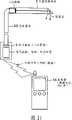
图1是从正面观察到的在人的头部M佩戴了根据本发明的一个实施例的头部佩戴型显示器(图像显示装置)1的样子的示意图。此外,图2(a)是表示图1的情况下的脸侧面的图,(b)是从上面观察到的图。该例子是利用小型的耳机型的头部支持部10的例子。在图1、2中,内置有用于可观察位于脸端部的显示面板的光导的目镜窗保持部2从头部支持部10延伸到眼球E前面附近。通过从该目镜窗保持部2的前端部的目镜窗4观察,可确认所显示的图像。此时,为了不妨碍观察外界景色,将位于眼球正面范围(参照图1)内的部件全部设为宽度4mm以下。FIG. 1 is a schematic view of a person wearing a head mounted display (image display device) 1 according to an embodiment of the present invention on a person's head M, viewed from the front. In addition, FIG. 2( a ) is a view showing the side of the face in the case of FIG. 1 , and (b) is a view seen from above. This example is an example using a small headphone
在此,对将位于眼球正面范围内的部件全部设定为宽度4mm以下的理由进行说明。人的瞳孔直径根据亮度在2~8mm之间变化。当配置在眼球正面的遮蔽物比瞳孔直径小的情况下,远方的景色不会被遮蔽物遮挡,可进行观察。在此,以平均的瞳孔直径尺寸为基准,通过将构成作为位于眼球正面范围内的框体部件的目镜窗保持部2的部件设为4mm以下的尺寸,从而在几乎所有的通常使用环境中,可在不遮挡外界的情况下进行观察。Here, the reason why all the components located in the front of the eyeball are set to have a width of 4 mm or less will be described. The diameter of the human pupil varies between 2 and 8mm according to the brightness. When the shield arranged in front of the eyeball is smaller than the diameter of the pupil, the distant scenery can be observed without being blocked by the shield. Here, on the basis of the average pupil diameter size, by setting the components constituting the
此外,在图1、2的例子中,棒状延伸的头部支持部10可以通过后记的荧光树脂棒来形成。此外,在耳机型的头部支持部10内,也可以内置辅助照明光源或显示面板驱动基板、各种控制基板、各种信息处理基板、存储器、通信功能、扬声器、操作接口等。In addition, in the example of FIG. 1, 2, the
图3是从正面观察到的光导未内置于目镜窗保持部2中的结构例的示意图。由保持在头部支持部10上的安装有显示面板的影像射出部11、保持在头部支持部10上的用于保持目镜光学系统5的目镜窗保持部2、以及保持在目镜窗保持部2上的目镜光学系统5构成,来自显示面板的射出光不通过目镜窗保持部2的内侧,而通过外侧即空中,直接入射到目镜光学系统5中。该情况下的目镜窗保持部2也设定为从眼球正面范围来看,宽度4mm以下,长度10mm以上。FIG. 3 is a schematic diagram of a structural example in which the light guide is not built into the eyepiece
该图3的情况在图1~图2的结构的效果之上,通过将目镜窗保持部2配置在光路外,可远离视野中心,可更加自然地观察外界和电子图像的双方。In the case of FIG. 3 , in addition to the effects of the structures in FIGS. 1 to 2 , by arranging the
图4(a)是图1的结构的光学系统部分的透视立体图,图4(b)是从上侧观察到的图。从内置于目镜窗保持部2的入射端近旁的显示面板3射出的影像光通过目镜窗保持部2的内部,通过反射材料6改变方向,而从目镜窗4向眼球E方向射出。观察者通过观察该目镜窗4,可观察到显示在显示面板3上的图像。目镜窗保持部2的左端实际上与头部支持部10连着,成为被头部M所保持的结构。此时,从观察者方向观察,目镜窗保持部2的宽度在4mm以下,目镜窗保持部2的长度在10mm以上。该情况下的反射部件只要是反射光线的部件,任何部件均可,例如可利用棱镜、反射镜等。此外,该情况下的显示面板3只要是小型的显示面板,任何面板均可,例如可利用透过型或者反射型的液晶显示元件、自发光型的有机EL元件、无机EL等。FIG. 4( a ) is a perspective perspective view of the optical system portion of the structure of FIG. 1 , and FIG. 4( b ) is a view seen from the upper side. The image light emitted from the display panel 3 built in near the incident end of the
图5中表示本发明的头部佩戴型图像显示装置的光学系统的基本结构。通过把配置在比近点调节极限更近位置处的显示面板3通过目镜5向眼球E投影其影像光,观察者可扩大观察作为显示面板3的虚像的空中像3’。通过这样的结构,即使使用小型的显示元件(显示面板3),也能够以大的观察视场角观察该显示像。FIG. 5 shows the basic configuration of the optical system of the head mounted image display device of the present invention. By projecting the image light of the display panel 3 arranged at a position closer than the near point adjustment limit to the eyeball E through the eyepiece 5, the observer can expand and observe the aerial image 3' which is a virtual image of the display panel 3. With such a configuration, even if a small display element (display panel 3 ) is used, the display image can be observed with a large viewing angle of view.
该情况下的目镜镜5只要是具有正屈光力的光学系统即可,可以是任意系统,例如可利用凸透镜、凹面镜、折射率不均匀的透镜等。此外,目镜镜5可使用组合多个具有正的或负的屈光力的光学元件形成正透镜组的结构。The eyepiece lens 5 in this case may be any optical system as long as it has a positive refractive power. For example, a convex lens, a concave mirror, a lens with non-uniform refractive index, etc. may be used. In addition, the eyepiece lens 5 may use a structure in which a plurality of optical elements having positive or negative refractive powers are combined to form a positive lens group.
图6是用于使用示意图来说明根据本发明的显示装置的外界遮蔽的样子的图。在图6中,示出了即使遮蔽物(在此为显示装置的框体。主要与图1~图4的目镜窗保持部2对应。)在眼球E正面的情况下,在遮蔽物比瞳孔直径细的情况下,也不会完全遮蔽远方的外界像的原理。在此,当把来自远方的某一点的光设为入射光时,则其作为大致平行的光入射到眼球E中。此时,如果遮蔽物比瞳孔直径小,则平行光的一部分通过瞳孔,在视网膜上的对应点成像。因此,即使在眼球正面存在遮蔽物(显示装置的框体)等,只要是粗细比瞳孔直径小的遮蔽物,就可以在不损失外界信息的情况下进行观察(成为透视)。FIG. 6 is a diagram for explaining the state of external shading of the display device according to the present invention using a schematic diagram. In Fig. 6, it is shown that even if the shield (here, the frame of the display device. Mainly corresponds to the eyepiece
在图6中,当外界变亮使用者的瞳孔收缩的情况下,引起眼球正面方向的外界视野被隔断、无法看见外界视野的现象。因此,在此,如图7(a)所示,当将遮蔽物(显示装置的框体)从眼球正面(视轴)方向移开时,可更加自然地观察外界像。而且,此时,尽管遮蔽物配置在瞳孔的一端,也可在眼球正面方向观察到显示装置的空中像(虚像),也得到完全的透视效果。即,例如图7(b)中的光路图所示,通过使观察外界的使用者的眼球光轴(视轴)与本发明的显示装置的光轴互相平行,从而看作在外界像上重叠本发明的显示装置显示的像(成为透视)。In FIG. 6 , when the outside world becomes brighter and the user's pupils contract, the external field of view in the front direction of the eyeball is cut off, making it impossible to see the external field of view. Therefore, here, as shown in FIG. 7( a ), when the shield (frame of the display device) is moved away from the front of the eyeball (visual axis), the external image can be observed more naturally. Moreover, at this time, although the shield is arranged at one end of the pupil, the aerial image (virtual image) of the display device can be observed in the front direction of the eyeball, and a complete see-through effect can also be obtained. That is, for example, as shown in the optical path diagram in FIG. 7(b), by making the optical axis (visual axis) of the user's eyeball observing the outside world and the optical axis of the display device of the present invention parallel to each other, it can be regarded as overlapping on the external image. The image displayed by the display device of the present invention (referred to as see-through).
以上这样,通过将作为位于眼球E的前方的遮蔽物的目镜窗保持部2设为10mm以上的长度,且比人的平均瞳孔直径4mm细,可如图6所示那样,不会完全遮蔽来自外界的光束,犹如透过目镜保持部2那样可观察、看清存在于与目镜窗保持部2的眼球E相反方向的外界像。因为外界光不通过目镜窗保持部2的内部,所以不产生现有技术中成为问题的不必要反射。即,As above, by setting the
可得到具有以下特征的环视效果:A look-around effect can be obtained with the following characteristics:
“轻量且小型”"Lightweight and compact"
“没有眩光”"no glare"
“较大的外界视野”。"Larger view of the outside world".
以下,示出内置于目镜窗保持部2中的光学系统的结构例。图8(a)是表示基本结构的图,由对来自显示面板3的光进行引导的目镜窗保持部2、向眼球方向改变光的方向的反射部件6、以及目镜镜5构成。根据该构造,通过尽量将大的体积大的显示面板3远离眼球,可使包含在眼球正面范围内的部位的宽度变细。Hereinafter, a configuration example of an optical system built in the eyepiece
但是,如果是图8(a)的结构,则显示面板3的尺寸受到构成目镜窗保持部2的部件的直径限制,当目镜窗保持部2变长时,存在不能把显示画面的视场角取得大的问题。于是,如图8(b)所示,通过将构成目镜窗保持部2的部件形成为锥形结构,通过使位于眼球正面范围内的部分尽量变细、使显示面板3的部分加大,可使用易于制造的尺寸的显示面板3,视场角也可以变大。But if it is the structure of Fig. 8 (a), the size of the display panel 3 is limited by the diameter of the parts constituting the eyepiece
图9(a)、(b)是表示图8(a)和(b)的结构的视场角的差异的图。图9(a)为与目镜窗保持部2同一直径的框体21的结构,图9(b)是锥形结构的框体22,且目镜镜5侧变细、显示面板3侧变大。根据图9的比较,例如,以从框体21、22的中央附近直到目镜5进入眼球正面范围为条件进行考虑,则在图9(a)、(b)的任一方眼球正面范围内的框体的直径设为在4mm以下时,图9(b)的锥体结构的框体22一方视场角可以加大,显示面板3也可变大。其中,图9中以标号21示出光轴,以标号22示出来自显示面板3的端部的光线。9( a ) and ( b ) are diagrams showing differences in viewing angles in the configurations of FIGS. 8( a ) and ( b ). Fig. 9 (a) is the structure of a frame body21 with the same diameter as the eyepiece
这样,通过尽量使得眼球正面范围内的框体变细,可更加清晰地观察外界。此外,由于可以把显示面板3增大,可增大视场角,可更多地形成可提示的信息量,并且显示面板3的制造也变得容易。In this way, by making the frame in the front of the eyeball as thin as possible, it is possible to observe the outside world more clearly. In addition, since the display panel 3 can be enlarged, the viewing angle can be increased, the amount of information that can be presented can be increased, and the manufacture of the display panel 3 becomes easy.
图10是在目镜窗保持部2内的光路中使用2个反射部件6、6’来构成的例子的图,通过2个反射部件6、6’将光路折弯2次,有时对背光灯的配置、与头部支持部10之间的连接有利。即,通过2次折弯光路,可提高布局上的自由度。FIG. 10 is a diagram of an example in which two reflective members 6, 6' are used in the optical path in the
图11表示在目镜窗保持部2中内置光学系统的情况下,作为该光学系统利用折射率分布型透镜23的例子的图,通过使用这样的折射率分布型透镜23,与以通常的凸透镜来构成目镜光学系统相比,可通过细的目镜窗保持部2的直径来实现视场角大的显示面。即,图11(b)示出以通常的目镜(凸透镜)5来构成目镜光学系统的情况的视场角,图11(c)中示出以折射率分布透镜23来构成的情况下的视场角,关注从显示面板3的端部射出、通过目镜窗中央的光线22,在两结构中均传过光导从目镜窗射出,但当观察图11(c)的由折射率分布透镜23构成的一方时,光线22在光导中逐渐改变方向,与此相对,在由通常的目镜5构成的图11(b)的结构中,光线22直线前进,因此射出时的视角(视场角)不同,可以明了利用了图11(c)的折射率分布透镜23的一方视场角变大。FIG. 11 shows a diagram of an example in which an optical system is built in the
这样,通过在目镜窗保持部2内在目镜光学系统中使用折射率分布型透镜23,可通过更细的直径来实现较大的视场角。Thus, by using the distributed refractive index lens 23 in the eyepiece optical system in the eyepiece
在此,讨论显示面板3的有效直径和目镜5的焦距之间的关系。图12中示出本发明的显示装置的光学系统的各参数之间的关系。当把显示元件的有效显示面的对角尺寸(有效直径)设为D、电子像视野的半视场角设为ω/2、目镜光学系统的焦距设为f时,根据近轴光学理论,存在以下关系:Here, the relationship between the effective diameter of the display panel 3 and the focal length of the eyepiece 5 is discussed. FIG. 12 shows the relationship between the parameters of the optical system of the display device of the present invention. When the diagonal size (effective diameter) of the effective display surface of the display element is set to D, the half field angle of the electronic image field is set to ω/2, and the focal length of the eyepiece optical system is set to f, according to the paraxial optical theory, The following relationship exists:
ω/2=(D/2)/f …(1)。ω/2=(D/2)/f ... (1).
当把主光线可通过使用者的瞳孔的主光线最大倾斜角设为ξ,把使用者的瞳孔直径设为d、把工作距离设为W时,存在以下关系:When the maximum inclination angle of the chief ray that can pass through the user's pupil is set as ξ, the diameter of the user's pupil is set as d, and the working distance is set as W, the following relationship exists:
ξ=(d/2)/W …(2)。ξ=(d/2)/W ... (2).
一直到周边都可以清楚地看到图像的条件为:The conditions under which the image can be seen clearly all the way to the periphery are:
ω/2<ξ …(3),ω/2<ξ
因此,D/f<d/W …(4)。Therefore, D/f<d/W ...(4).
其中,室内的使用者的瞳孔的直径d最大为5mm左右,,此外考虑瞬时的睫毛的干涉等,需确保的工作距离W为10mm左右,因此把d=5mm、W=10mm分别代入不等式(4)中,得到Among them, the maximum diameter d of the pupil of the indoor user is about 5mm. In addition, considering the interference of the eyelashes, etc., the working distance W to be ensured is about 10mm. Therefore, d=5mm and W=10mm are respectively substituted into the inequality (4 ), get
D/f<0.5 …(5)。D/f<0.5 ...(5).
通过把显示装置的出射光瞳位置设置在目镜窗近旁或者目镜窗与使用者的眼镜的瞳孔之间,可减小观察图像周边的光束的黑框,但如果D/f在不等式(5)的上限的0.5以上,则产生黑框。By setting the exit pupil position of the display device near the eyepiece window or between the eyepiece window and the pupil of the user's glasses, the black frame of the light beam around the observed image can be reduced, but if D/f is in the equation (5) Above 0.5 of the upper limit, a black frame is generated.
这样,通过在本发明的显示装置的光学系统中设定D/f<0.5的条件,在成为小型的装置的同时,可观察到在观察时没有黑框的电子影像。Thus, by setting the condition of D/f<0.5 in the optical system of the display device of the present invention, it is possible to observe an electronic image without a black frame during observation while making the device compact.
此外,优选本发明的显示装置的显示面板3的照明用的光源利用外界光。此时,可使用荧光树脂棒来构成该照明光源。以下,示出该例子。In addition, it is preferable that the light source for illuminating the display panel 3 of the display device of the present invention utilizes external light. At this time, fluorescent resin rods may be used to form the illumination light source. This example is shown below.
图13是关于用于在背光灯中利用外界光的荧光树脂棒的说明图。荧光树脂棒30是指将包含荧光物质41的树脂加工成棒状的部件。当外界光42从侧面等入射到该荧光树脂棒30时,被荧光物质41吸收,接着以荧光物质41作为光源发出光。此时该部件为棒状,在内部发出的光43在内部的侧面反复进行全反射,并从棒端面射出。即,在棒内部发光且被封闭在棒内部的光从棒端面射出,因此棒端面非常亮地发光。同样地,与用作为背光灯一侧的端面相反方向的端面也发光,但是通过将不利用的端面设为反射镜44,所反射的光仅从利用侧的端面射出,因此,可有效地利用背光灯的光。此外,作为反射镜44,可以在棒端面上蒸镀金属薄膜,也可以是角隅棱镜那样的利用全反射的棱镜。Fig. 13 is an explanatory view regarding a fluorescent resin rod used for utilizing external light in a backlight. The fluorescent resin rod 30 refers to a member processed into a rod shape from resin containing the fluorescent substance 41 . When external light 42 enters the fluorescent resin rod 30 from the side, etc., it is absorbed by the fluorescent material 41 and then emits light using the fluorescent material 41 as a light source. At this time, the member is in the shape of a rod, and the light 43 emitted inside undergoes repeated total reflection on the side surface of the inside, and is emitted from the end surface of the rod. That is, since the light emitted inside the rod and the light enclosed inside the rod is emitted from the end face of the rod, the end face of the rod emits light very brightly. Similarly, the end face in the opposite direction to the end face used as the backlight side also emits light, but by making the unused end face a reflector 44, the reflected light is only emitted from the end face on the utilization side, so it can be effectively used. Backlight light. In addition, as the reflecting mirror 44, a metal thin film may be vapor-deposited on the end surface of the rod, or a prism utilizing total reflection such as a corner cube may be used.
而且,从加工为棒状的部件的侧面入射的外界光42也会未被荧光物质41吸收,不满足棒的全反射条件的光从侧面漏出,但通过在外界光42非入射侧或者佩戴时作为内侧的部分处配置反射镜45,从而可再利用未被利用的光中的一部分。Moreover, the external light 42 that is incident from the side of the rod-shaped component will not be absorbed by the fluorescent substance 41, and the light that does not satisfy the total reflection condition of the rod leaks from the side, but passes through the non-incident side of the external light 42 or when worn. Reflecting mirrors 45 are arranged on the inside so that part of unused light can be reused.
此外,当把利用了该结构的照明用作为显示面板3的照明光46时,根据外界的亮度照明光46的亮度变化。此现象一般在透视功能使用时,与当外界越亮时需要更加亮的照明,当外界暗时,少的照明即可的利用情景一致。In addition, when the illumination utilizing this structure is used as the illumination light 46 of the display panel 3, the brightness of the illumination light 46 changes according to the brightness of the outside world. This phenomenon is generally consistent with the use of the see-through function, which requires brighter lighting when the outside world is brighter, and less lighting when the outside world is dark.
图14、15是表示利用了这样的荧光树脂棒30的显示装置的结构例的图。二者均将从荧光树脂棒30端面射出的照明光入射到显示面板31或者36中,显示面板31或者36的影像光在目镜窗保持部2内导光,从目镜窗4中射出。在此,荧光树脂棒30与头部支持部10连接,或者,荧光树脂棒30自身成为头部支持部10。14 and 15 are diagrams showing configuration examples of a display device using such a fluorescent resin rod 30 . Both of them inject the illumination light emitted from the end surface of the fluorescent resin rod 30 into the display panel 31 or 36 , and the image light of the display panel 31 or 36 is guided in the eyepiece
图14(a)、(b)、图15(a)是利用了透过型显示面板31的结构,图15(b)是利用了反射型显示面板36的结构。在图15(b)的情况下,为了使照明光46从反射型显示面板36的前面入射,在反射型显示面板36的显示侧配置半透半反镜等的光路分离光学元件49。14( a ), ( b ) and FIG. 15( a ) are structures using the transmissive display panel 31 , and FIG. 15( b ) is a structure using the reflective display panel 36 . In the case of FIG. 15( b ), an optical path splitting optical element 49 such as a half mirror is disposed on the display side of the reflective display panel 36 in order to make illumination light 46 incident from the front of the reflective display panel 36 .
图16是表示将荧光树脂部件和导光板进行组合作为显示面板的背光灯的结构例的图,图16(a)通过在构成为板状的荧光树脂板30’的一部分上设置出射槽47,从该部分射出光,作为显示面板31的背光灯。图16(b)是将从荧光树脂棒30的一端射出的光入射到与荧光树脂棒30连接的另一部件的导光板48上,导光板48通过从其侧面向显示面板31方向射出所引导的光的功能,对显示面板31进行照明。这样,通过组合荧光树脂部件和导光板,可将外界光用作为显示面板用照明。此外,通过这样的导光板,即使在荧光树脂棒端面比显示面板小时,也可均匀地照明整个显示面板。16 is a diagram showing a combination of a fluorescent resin member and a light guide plate as a structural example of a backlight for a display panel. FIG. Light is emitted from this portion as a backlight of the display panel 31 . Fig. 16 (b) is that the light emitted from one end of the fluorescent resin rod 30 is incident on the light guide plate 48 of another part connected with the fluorescent resin rod 30, and the light guide plate 48 is guided by emitting light from its side toward the display panel 31. The function of light is to illuminate the display panel 31 . In this manner, by combining the fluorescent resin member and the light guide plate, external light can be used as illumination for the display panel. Furthermore, with such a light guide plate, even if the end faces of the fluorescent resin rods are smaller than the display panel, the entire display panel can be uniformly illuminated.
这样,通过利用荧光树脂部件作为背光灯,可在显示面板的照明中利用外界光,因此可低耗电化,此外,与外界的亮度相对应照明光量自然地变化,因此无需安装特殊的传感器即可根据利用环境,进行适当的照明。此外,可价廉地构成利用外界光的背光灯。In this way, by using the fluorescent resin member as the backlight, the external light can be used for the illumination of the display panel, so the power consumption can be reduced. In addition, the amount of illumination light changes naturally according to the brightness of the outside world, so there is no need to install a special sensor. Appropriate lighting can be provided according to the usage environment. In addition, a backlight utilizing external light can be configured at low cost.
图17表示利用了荧光树脂棒30的另一结构例。在图17中,使用透过型液晶显示元件31作为显示元件,在该显示元件31的照明中使用上述的荧光树脂棒30,荧光树脂棒30被外界光照射,通过自发荧光而发光,该发出的光在荧光树脂棒30内部全反射并从其端面射出,经由反射棱镜33和照明用透镜32,由该自发荧光实现的照明光照明显示元件31。荧光树脂棒30的非透过型液晶显示元件31侧的端面设为全反射棱镜(角隅棱镜)34的形状,折返与显示元件31反向行进的荧光进行再利用。并且,在该例子中,在显示元件31和目镜窗4之间配置一端为90°全反射型的透明棒9,在透明棒9的光路90°弯曲的射出端的目镜窗4位置处贴有构成目镜的凸透镜15,其构成为全部被目镜窗保持部2覆盖。因此,目镜的凸透镜15和目镜窗4成为一体。在该例子中,荧光树脂棒30被用作为照射显示元件31的照明光源,可减小头部佩戴型图像显示装置的耗电,而且,当外界亮时,光源亮度也上升,因此可避免电子影像亮度比外界的亮度弱而难以看清的问题。此外,在图17的例子中,荧光树脂棒30在未使用时,如图18所示,可以以铰链旋转轴35为中心向箭头方向折叠而收纳。通过这样构成,即使在搭载在眼镜上的状态下,也可以与眼镜一起折叠收纳。FIG. 17 shows another structural example using fluorescent resin rods 30 . In FIG. 17, a transmissive liquid crystal display element 31 is used as a display element, and the above-mentioned fluorescent resin rod 30 is used for illumination of the display element 31. The fluorescent resin rod 30 is irradiated by external light and emits light by autofluorescence. The light is totally reflected inside the fluorescent resin rod 30 and emitted from the end surface, and the display element 31 is illuminated by the illumination light realized by the autofluorescence through the reflection prism 33 and the illumination lens 32 . The end surface of the fluorescent resin rod 30 on the side of the non-transmissive liquid crystal display element 31 is shaped like a total reflection prism (corner cube) 34, and the fluorescent light traveling in the opposite direction to the display element 31 is turned back and reused. And, in this example, between the display element 31 and the
图19是表示在通常使用的眼镜上安装了本发明的头部佩戴型图像显示装置的例子的图。沿着眼镜框50配置荧光树脂棒30,来自其端面的光被反射部件折弯90°一次,入射到显示面板31上,将来自显示面板31的影像光向目镜窗保持部2内引导,并从目镜窗4射出。此时,荧光树脂棒30的另一端面为了提高光的利用效率也可设置反射镜44,此外,在外界光42不照射的眼镜框50和荧光树脂棒30之间的边界处也可设置反射镜45。而且,通过利用辅助光源37,在完全黑暗中也可利用。在此,在荧光设置棒30的另一端配置辅助光源37,可切换反射镜44和辅助光源37来使用。FIG. 19 is a diagram showing an example in which the head-mounted image display device of the present invention is mounted on commonly used glasses. The fluorescent resin rod 30 is arranged along the
辅助光源37发出的光的波长可以与可有效地激励荧光树脂棒30的荧光物质的波长范围抑制。由此,荧光树脂棒30被来自辅助光源37的辅助光有效地激励,通过该荧光来照明显示面板31,因此辅助光源37可以通过较少的耗电来实现明亮的照明。The wavelength of the light emitted by the auxiliary light source 37 can be restrained from the wavelength range that can effectively excite the fluorescent material of the fluorescent resin rod 30 . As a result, the fluorescent resin rod 30 is efficiently excited by the auxiliary light from the auxiliary light source 37, and the display panel 31 is illuminated by the fluorescent light. Therefore, the auxiliary light source 37 can realize bright lighting with less power consumption.
或者,辅助光源37发出的光的波长可以避开荧光树脂棒30的吸收度大的波长范围,由此辅助光源37发出的光可以不被荧光树脂棒30吸收而照明显示面板31,因此辅助光源37可以通过较少的耗电来实现明亮的照明。Or, the wavelength of the light emitted by the auxiliary light source 37 can avoid the wavelength range where the absorption of the fluorescent resin rod 30 is large, so that the light emitted by the auxiliary light source 37 can illuminate the display panel 31 without being absorbed by the fluorescent resin rod 30, so the auxiliary light source 37 can achieve bright lighting with less power consumption.
而且,辅助光源37发出的光的颜色可设为与荧光树脂棒30发出的荧光色不同的颜色,在促使使用者注意时,使该辅助光源37闪烁。通过该闪烁,使用者观察的图像不仅是其亮度,而且颜色也变化,容易被注意到。Moreover, the color of the light emitted by the auxiliary light source 37 can be set to a color different from the fluorescent color emitted by the fluorescent resin rod 30 , and the auxiliary light source 37 can be made to blink when drawing the user's attention. By this flickering, not only the brightness but also the color of the image observed by the user changes, which is easy to be noticed.
此外,在将荧光树脂棒30配置在头部侧面时,在外界光照射不到的部分、头部和荧光树脂棒30之间即使配置电气基板和布线等,也不会妨碍外界光的入射。In addition, when the fluorescent resin rod 30 is arranged on the side of the head, even if an electric substrate and wiring are arranged between the head and the fluorescent resin rod 30 in the part where the external light is not irradiated, the incidence of external light will not be hindered.
这样,通过在通常的眼镜上安装本发明的头部佩戴型图像显示装置,平常使用眼镜的人也可使用本发明的头部佩戴型图像显示装置。此外,此时,通过设置辅助光源,也可应对暗的环境。而且,使用荧光树脂棒作为利用外界光的照明光源,通过考虑该荧光树脂的吸收波长来选定辅助光源,实现低耗电化。通过使用与该荧光树脂的荧光色不同的波长的辅助光源,可用作为唤起注意的信号。而且,通过在荧光树脂棒的外光入射部的相反侧配设布线、基板类,不会妨碍外光入射。In this way, by attaching the head-mounted image display device of the present invention to normal glasses, people who usually use glasses can also use the head-mounted image display device of the present invention. In addition, at this time, by installing an auxiliary light source, it is also possible to cope with a dark environment. Furthermore, a fluorescent resin rod is used as an illumination light source utilizing external light, and an auxiliary light source is selected in consideration of the absorption wavelength of the fluorescent resin to realize low power consumption. By using an auxiliary light source having a wavelength different from the fluorescent color of the fluorescent resin, it can be used as a signal to call attention. Furthermore, by arranging wiring, substrates and the like on the side opposite to the external light incident portion of the fluorescent resin rod, external light incidence is not hindered.
图20是表示将本发明的头部佩戴型图像显示装置组装入眼镜框的例子的图。目镜窗保持部2组装入眼镜框50内部,在图中在眼镜镜片51的中央下部有目镜窗4,射出影像光。这样,通过一开始即在眼镜框上组装上本发明的头部佩戴型图像显示装置,无需烦杂的佩戴作业、无需佩戴机构等,因此可实现更加自然的设计。FIG. 20 is a diagram showing an example of incorporating the head-mounted image display device of the present invention into a spectacle frame. The eyepiece
图21是利用了光纤像导的结构例的图。在头部佩戴型图像显示装置中,消除佩戴时的烦琐性是重要的,为此,期待配置在眼睛附近的部件尽可能的小。通常,在眼睛附近配置显示面板,眼睛附近的装置变得大型化。于是,将显示面板3从眼睛处离开,通过光纤像导55来将显示面板3的影像传送到眼睛附近,把传送的影像作为二次影像,通过光学系统对该二次影像进行放大观察,可极力减小配置在眼睛附近的装置。此外,光纤像导55具有一定程度的柔软性,因此可折弯使用,成为易于与各种设计和调整机构相对应的结构。Fig. 21 is a diagram of a configuration example using an optical fiber image guide. In a head-mounted image display device, it is important to eliminate the troublesomeness when wearing it. For this reason, it is desired that the components arranged near the eyes be as small as possible. Usually, a display panel is placed near the eyes, and the size of the device near the eyes becomes large. Then, the display panel 3 is separated from the eyes, and the image of the display panel 3 is transmitted to the vicinity of the eyes through the optical
此外,在图21中示出了从无线连接的控制器56接收影像和信息,在显示面板3上显示的情形。在此所说的控制器56可以是专用的控制器或便携电话、便携式信息设备(PDA)等的任何一个。In addition, FIG. 21 shows a state in which images and information are received from the wirelessly connected controller 56 and displayed on the display panel 3 . The controller 56 mentioned here may be any one of a dedicated controller, a mobile phone, a portable information device (PDA), and the like.
以上这样,通过使用光纤像导作为二次影像来传送显示面板的影像,显示面板或布线、电气基板类无需配置在眼睛附近,可以防止对佩戴感和设计带来不好影响的眼睛附近的装置的大型化。此外,光纤像导具有一定程度的柔软性,因此可折弯使用,易于与各种设计和调整机构相对应。As described above, by using the optical fiber image guide as the secondary image to transmit the image of the display panel, the display panel, wiring, and electrical substrates do not need to be placed near the eyes, and devices near the eyes that adversely affect the wearing feeling and design can be prevented. of upsizing. In addition, the fiber optic image guide has a certain degree of flexibility, so it can be bent and used, and it is easy to correspond to various designs and adjustment mechanisms.
在图21这样的结构中,当普及基于无线的影像和信息交换时,会产生信息泄漏的问题。也会产生仅用电气或者软件对策存在不安全的情况。在该情况下有效的是组装了加密光纤像导的头部佩戴型图像显示装置。图22是说明加密光纤像导57的结构和作用的图,在通常的光纤像导中,在显示面板3上显示的图像以原样的图形来传送。例如,对于显示面板3上的1个像素配置1根光纤,原样维持像素的相对配置来传送影像。在此所说的加密光纤像导是指对显示面板3上的1个像素分配1根光纤58,在传送的途中,通过随机替换光纤58的相对配置,来显示与显示面板3上的影像完全不同的图形的影像。在图中,虽然在显示面板3上显示了完全不成意思的图像,传送图像的光纤58的配置在途中相互替换,因此在传送后的二次影像上显示文字“F”。In the structure shown in FIG. 21, when wireless video and information exchange become widespread, there will be a problem of information leakage. There may also be cases where only electrical or software countermeasures are unsafe. In this case, a head-mounted image display device incorporating an encrypted optical fiber image guide is effective. FIG. 22 is a diagram for explaining the structure and function of the encrypted optical
通过预先调查显示面板3上的像素和传送的二次影像上的像素之间的对应关系,以像素为单位替换在显示面板3上实际显示的影像,以使作为二次影像看到整齐的影像。从控制器56侧以无线信号发送作为该替换后的影像的完全不成意思的图像信息,因此即使他人在旁边接收,该人也只能看到完全不成意思的影像,因此保证了安全性。此外,该加密光纤像导57为每个产品而不同的固有的配置,即使使用相同产品,他人也无法从旁边接收(图24)。By investigating the correspondence between the pixels on the display panel 3 and the pixels on the transmitted secondary image in advance, the image actually displayed on the display panel 3 is replaced in units of pixels, so that a neat image can be seen as the secondary image . Since the completely meaningless image information as the replaced video is transmitted by wireless signal from the controller 56 side, even if another person receives it nearby, the person can only see the completely meaningless video, thereby ensuring safety. In addition, this encrypted optical
这样,从与显示部另外构成的控制器(图像数据发送部)通过无线电发送影像和信息时,在软件、电气安全对策之上,在物理(光学)结构上也提高了安全性。In this way, when images and information are transmitted by radio from the controller (image data transmission unit) configured separately from the display unit, security is improved in terms of physical (optical) structure in addition to software and electrical safety measures.
图23是图像缩小光纤像导55’的说明图。在现有的技术中,难以制造非常小的显示面板,成本高。但是,使用制造容易的尺寸的显示面板,尽量在不妨碍的部分佩戴,通过图像缩小光纤像导55’形成比显示面板3更小的二次影像,通过光学系统观察该图像,在使用较大的显示面板的同时,可实现在眼睛附近紧凑的佩戴感的头部佩戴型图像显示装置。Fig. 23 is an explanatory diagram of the image reduction fiber optic image guide 55'. In the existing technology, it is difficult to manufacture a very small display panel, and the cost is high. However, use a display panel with a size that is easy to manufacture, and wear it on a part that does not interfere as much as possible, and form a secondary image that is smaller than the display panel 3 through the image reduction optical fiber image guide 55 ′, and observe the image through an optical system. It is a head-mounted image display device that can realize a compact wearing feeling near the eyes while using a large display panel.
这样,通过利用图像缩小光纤像导,可在眼睛附近显示比实际的显示面板小的影像作为二次影像。本发明的头部佩戴型图像显示装置使用极端小的类型的显示面板作为显示面板,但由此可使用容易制造且成本低的稍大的显示面板。In this way, by using the image reduction fiber optic image guide, an image smaller than the actual display panel can be displayed as a secondary image near the eyes. The head-mounted image display device of the present invention uses an extremely small type of display panel as the display panel, but thus can use a slightly larger display panel that is easy to manufacture and low in cost.
图24是使用了图22这样的加密光纤像导的设备的内容发布的示意图。有产品No.1~3的产品,在各自中加密光纤像导的配置不同,对其进行解析编码后成为密钥。内容发布中心具有与各个产品No.对应的密钥的信息,根据该信息对视频信号进行图像处理。然后,向持有对应的产品No.的人发布图像处理后的内容数据。通过这些处理,该内容数据只能在具有某一特定的No.的产品上才能看到,即使在得到对其它产品的复制或者不正当地得到了内容的情况下,在用其它产品进行再现的情况下,为完全不成意思的图像。因此,可解决在数字内容发布时成为问题的非法复制或非法使用的问题。FIG. 24 is a schematic diagram of publishing content of the device using the encrypted optical fiber image guide as shown in FIG. 22 . There are products No. 1 to 3, each of which has a different configuration of the encrypted optical fiber image guide, which is analyzed and coded to become a key. The content distribution center has information on the key corresponding to each product No., and performs image processing on the video signal based on the information. Then, the image-processed content data is distributed to those who have the corresponding product No. Through these processes, the content data can only be seen on a product with a certain No., even if the copy of other products is obtained or the content is illegally obtained, in the case of reproduction with other products Below, a completely uninteresting image. Therefore, it is possible to solve the problem of illegal copying or illegal use that becomes a problem when digital content is distributed.
以上的本发明的头部佩戴型图像显示装置例如可如以下这样构成。The head-mounted image display device of the present invention described above can be configured as follows, for example.
[1]一种头部佩戴型图像显示装置,其至少由以下部分构成:显示元件;目镜光学系统;目镜窗;目镜窗保持部;框体;以及用于将这些全部固定在使用者头部的支持部,其特征在于,框体覆盖显示元件,目镜窗保持部将目镜窗保持在使用者的视野内,目镜光学系统形成显示元件显示的显示图像的虚像,目镜窗是向使用者的眼睛射出形成该虚像的光束的窗,构成目镜窗保持部的部件在从所述目镜窗向着根部10mm以上的范围内,除了一部分的突起,在该使用者的视轴方向的投影截面的宽度在4mm以下,具有环视功能。[1] A head-mounted image display device comprising at least the following parts: a display element; an eyepiece optical system; an eyepiece window; an eyepiece window holding portion; a frame body; The supporting part is characterized in that the frame covers the display element, the eyepiece window holding part keeps the eyepiece window in the user's field of vision, the eyepiece optical system forms a virtual image of the display image displayed by the display element, and the eyepiece window is facing the user's eyes. The window that emits the light beam that forms the virtual image, and the components that constitute the eyepiece window holding part are within a range of 10 mm or more from the eyepiece window to the base, except for a part of the protrusion, and the width of the projected section in the direction of the user's visual axis is 4 mm. Below, it has a look-around function.
[2]根据上述1所述的头部佩戴型图像显示装置,其特征在于,构成目镜窗的部件在该使用者的视轴方向的投影截面的宽度在4mm以下,具有透视功能。[2] The head-mounted image display device according to the above 1, wherein the member constituting the eyepiece window has a projection cross-sectional width of 4 mm or less in the direction of the visual axis of the user and has a see-through function.
[3]根据上述1或2所述的头部佩戴型图像显示装置,其特征在于,在目镜窗保持部和目镜窗之间,配置有将光轴向使用者的眼的方向折弯的全反射的反射镜或者棱镜。[3] The head-mounted image display device according to the above 1 or 2, wherein a full body for bending the optical axis in the direction of the user's eyes is arranged between the eyepiece window holding part and the eyepiece window. Reflective mirrors or prisms.
[4]根据上述1至3中的任一项所述的头部佩戴型图像显示装置,其特征在于,目镜窗保持部被保持为在头部佩戴时配置为大致水平。[4] The head-mounted image display device according to any one of 1 to 3 above, wherein the eyepiece window holding portion is held so as to be arranged substantially horizontally when worn on the head.
[5]根据上述3所述的头部佩戴型图像显示装置,其特征在于,具有能够以目镜窗保持部的长度方向为旋转轴对目镜窗和全反射的反射镜或者目镜窗和全反射的棱镜整体进行旋转调节的旋转机构。[5] The head-mounted image display device according to the above 3, characterized in that it has a mirror capable of aligning the eyepiece window and total reflection with the longitudinal direction of the eyepiece window holding part as the rotation axis, or the eyepiece window and total reflection Rotary mechanism for rotating and adjusting the entire prism.
[6]根据上述3所述的头部佩戴型图像显示装置,其特征在于,具有使用者可以以与显示元件的显示面垂直的方向为旋转轴对显示元件进行旋转调节的旋转机构。[6] The head-mounted image display device according to the above 3, characterized in that it includes a rotation mechanism that enables the user to rotate and adjust the display element with a rotation axis perpendicular to the display surface of the display element.
[7]根据上述1至6中的任一项所述的头部佩戴型图像显示装置,其特征在于,目镜光学系统的一部分或者全部与目镜窗成为一体。[7] The head-mounted image display device according to any one of 1 to 6 above, wherein part or all of the eyepiece optical system is integrated with the eyepiece window.
[8]根据上述1至7中的任一项所述的头部佩戴型图像显示装置,其特征在于,目镜光学系统的一部分或者全部内置于目镜窗保持部中。[8] The head-mounted image display device according to any one of 1 to 7 above, wherein a part or all of the eyepiece optical system is built in the eyepiece window holding portion.
[9]根据上述8所述的头部佩戴型图像显示装置,其特征在于,内置于目镜窗支持部中的目镜光学系统是具有会聚平行光束的作用的光学系统。[9] The head-mounted image display device according to the above-mentioned 8, wherein the eyepiece optical system built into the eyepiece window support portion is an optical system that functions to converge parallel light beams.
[10]根据上述1至9中任一项所述的头部佩戴型图像显示装置,其特征在于,框体和目镜窗保持部经由全反射的反射镜或棱镜或者光纤像导而连接。[10] The head-mounted image display device according to any one of 1 to 9 above, wherein the housing and the eyepiece window holder are connected via a total reflection mirror or prism or an optical fiber image guide.
[11]根据上述1至10中任一项所述的头部佩戴型图像显示装置,其特征在于,具有照明部,照明部和框体经由全反射的反射镜或棱镜、导光板、或光导而连接。[11] The head-mounted image display device according to any one of the above 1 to 10, characterized in that it has an illuminating unit, and the illuminating unit and the housing pass through a total reflection mirror or prism, a light guide plate, or a light guide. And connect.
[12]根据上述8所述的头部佩戴型图像显示装置,其特征在于,目镜光学系统由凸透镜构成。[12] The head-mounted image display device according to the above-mentioned 8, wherein the eyepiece optical system is formed of a convex lens.
[13]根据上述8或9所述的头部佩戴型图像显示装置,其特征在于,目镜光学系统由在径向上折射率逐渐变高的光学介质构成。[13] The head-mounted image display device according to the above 8 or 9, wherein the eyepiece optical system is composed of an optical medium whose refractive index gradually increases in the radial direction.
[14]根据上述1至13中的任一项所述的头部佩戴型图像显示装置,其特征在于,当设显示元件的有效显示面的对角尺寸为D、目镜光学系统的焦距为f时,满足D/f<0.5。[14] The head-mounted image display device according to any one of the above 1 to 13, characterized in that when the diagonal dimension of the effective display surface of the display element is D, and the focal length of the eyepiece optical system is f , satisfy D/f<0.5.
[15]根据上述14所述的头部佩戴型图像显示装置,其特征在于,出射光瞳位置位于目镜窗近旁或者在目镜窗与使用者的眼睛的瞳孔之间。[15] The head mounted image display device according to the above 14, wherein the exit pupil is positioned near the eyepiece window or between the eyepiece window and the pupil of the user's eye.
[16]根据上述1所述的头部佩戴型图像显示装置,其特征在于,射出显示元件的电子影像形成光束通过目镜窗保持部的外侧。[16] The head-mounted image display device according to the above 1, wherein the electronic image-forming light beam exiting the display element passes outside the eyepiece window holding portion.
[17]根据上述1所述的头部佩戴型图像显示装置,其特征在于,具有对显示元件进行照明的照明用光源,该光源由荧光树脂棒构成。[17] The head-mounted image display device according to the above 1, characterized in that it includes a light source for illuminating the display element, and the light source is made of a fluorescent resin rod.
[18]根据上述17所述的头部佩戴型图像显示装置,其特征在于,荧光树脂棒的朝向与显示面板相反侧的端面经过了镜面涂层处理或者形成为角隅棱镜形状。[18] The head-mounted image display device according to the above 17, wherein the end surface of the fluorescent resin rod facing the side opposite to the display panel is mirror-coated or formed into a corner cube shape.
[19]根据上述17所述的头部佩戴型图像显示装置,其特征在于,在荧光树脂棒的侧面不入射外界光侧的侧面上配置有反射镜。[19] The head-mounted image display device according to the above 17, wherein a reflection mirror is arranged on a side surface of the fluorescent resin rod on a side on which external light is not incident.
[20]根据上述1至19中的任一项所述的头部佩戴型图像显示装置,其特征在于,通过使用者的眼睛和目镜窗之间的位置关系,眼睛的视轴不与目镜窗重合,目镜窗的主光线入射进瞳孔径内。[20] The head-mounted image display device according to any one of 1 to 19 above, wherein the visual axis of the eye does not coincide with the eyepiece window due to the positional relationship between the user's eyes and the eyepiece window. Coincident, the chief ray of the eyepiece window enters the diameter of the pupil.
[21]根据上述1所述的头部佩戴型图像显示装置,其特征在于,构成目镜窗保持部的部件是目镜窗侧细、显示元件侧粗的锥形结构的部件。[21] The head-mounted image display device according to the above 1, wherein the member constituting the eyepiece window holding portion is a tapered member having a thinner eyepiece window side and a thicker display element side.
[22]根据上述1所述的头部佩戴型图像显示装置,其特征在于,通过目镜窗保持部和目镜窗观察通过光纤像导传送显示元件的影像而形成的二次影像。[22] The head-mounted image display device according to the above 1, wherein the secondary image formed by transmitting the image of the display element through the optical fiber image guide is observed through the eyepiece window holding portion and the eyepiece window.
[23]根据上述22所述的头部佩戴型图像显示装置,其特征在于,作为光纤像导使用不规则地排列的加密光纤像导,与该加密光纤像导相对应地,在显示元件上显示影像,以能够作为影像观察到二次影像。[23] The head-mounted image display device according to the above 22, wherein irregularly arranged encrypted optical fiber image guides are used as the optical fiber image guides, and corresponding to the encrypted optical fiber image guides, on the display element The image is displayed so that the secondary image can be observed as an image.
[24]根据上述22所述的头部佩戴型图像显示装置,其特征在于,使得在入射侧和出射侧的光纤像导的各像素的间距不同,以使得通过光纤像导传送的二次影像尺寸比显示元件上的影像尺寸小。[24] The head-mounted image display device according to the above-mentioned 22, wherein the pitch of each pixel of the optical fiber image guide on the incident side and the output side is different, so that the secondary image transmitted through the optical fiber image guide The size is smaller than the image size on the display device.
[25]根据上述1至24中任一项所述的头部佩戴型图像显示装置,其特征在于,包含显示元件的显示部、目镜窗保持部、目镜光学系统和目镜窗内置于眼镜框中。[25] The head-mounted image display device according to any one of 1 to 24 above, wherein the display unit including the display element, the eyepiece window holding unit, the eyepiece optical system, and the eyepiece window are built into the spectacle frame. .
产业上的利用可能性Industrial Utilization Possibility
在本发明的头部佩戴型图像显示装置中,构成目镜窗保持部的部件在使用者视轴方向的投影截面的宽度设为4mm以下,该目镜窗保持部件比人的平均瞳孔径(4mm)细,即使在视野内配置装置,也不会完全遮住外界,可得到透视效果。而且,不使用半透半反镜,没有光量的损失,因此可观察到明亮的电子图像。此外,显示电子图像的部位由于来自外界的光束被一部分目镜窗保持部结构部件遮挡而变暗,具有使电子图像的可见性变好的作用。而且,除了显示电子图像的部位,其它的外界视野均不会被遮挡,因此可取得与未使用本发明的装置时相同的亮度而得到明亮的视野。此外,因为是比瞳孔直径还细的装置,从外部看不会完全盖住佩戴者的眼睛,可传递更加自然的表情。In the head-mounted image display device of the present invention, the width of the projected section of the eyepiece window holding part in the direction of the user's visual axis is set to be 4 mm or less, and the eyepiece window holding part is smaller than the average pupil diameter (4 mm) of a person. Thin, even if the device is placed within the field of view, it will not completely cover the outside world, and a perspective effect can be obtained. Furthermore, since no half mirror is used, there is no loss of light quantity, so bright electronic images can be observed. In addition, the part where the electronic image is displayed becomes dark because the light beam from the outside is blocked by a part of the eyepiece window holding part structural member, which has the effect of improving the visibility of the electronic image. Moreover, except for the portion where the electronic image is displayed, other external views will not be blocked, so the same brightness as when the device of the present invention is not used can be obtained and a bright view can be obtained. In addition, since the device is thinner than the diameter of the pupil, it does not completely cover the wearer's eyes from the outside, and can convey a more natural expression.
Claims (25)
Applications Claiming Priority (2)
| Application Number | Priority Date | Filing Date | Title |
|---|---|---|---|
| JP2004145838 | 2004-05-17 | ||
| JP145838/2004 | 2004-05-17 |
Publications (2)
| Publication Number | Publication Date |
|---|---|
| CN1957284Atrue CN1957284A (en) | 2007-05-02 |
| CN100520490C CN100520490C (en) | 2009-07-29 |
Family
ID=35394297
Family Applications (1)
| Application Number | Title | Priority Date | Filing Date |
|---|---|---|---|
| CNB2005800159106AExpired - Fee RelatedCN100520490C (en) | 2004-05-17 | 2005-02-22 | head-mounted image display device |
Country Status (4)
| Country | Link |
|---|---|
| US (1) | US7719769B2 (en) |
| EP (1) | EP1757974B1 (en) |
| CN (1) | CN100520490C (en) |
| WO (1) | WO2005111693A1 (en) |
Cited By (24)
| Publication number | Priority date | Publication date | Assignee | Title |
|---|---|---|---|---|
| CN101846800A (en)* | 2009-03-25 | 2010-09-29 | 奥林巴斯株式会社 | Glasses-mounted type image display device |
| CN101846801A (en)* | 2009-03-25 | 2010-09-29 | 奥林巴斯株式会社 | Eyeglass-mounted type image display device |
| CN101846805A (en)* | 2009-03-25 | 2010-09-29 | 奥林巴斯株式会社 | Eyeglass-mounted type image display device |
| CN101900880A (en)* | 2008-12-18 | 2010-12-01 | 奥林巴斯株式会社 | Head-mounted type image display device |
| CN102004317A (en)* | 2009-08-31 | 2011-04-06 | 奥林巴斯株式会社 | Spectacles-type image display device |
| CN102169232A (en)* | 2011-05-23 | 2011-08-31 | 华北电力大学(保定) | Double-spectrum helmet display system |
| CN102200642A (en)* | 2011-05-23 | 2011-09-28 | 华北电力大学(保定) | Night dual-spectrum helmet mounted display |
| CN102445754A (en)* | 2010-10-08 | 2012-05-09 | 精工爱普生株式会社 | Virtual image display device |
| CN102449531A (en)* | 2009-03-13 | 2012-05-09 | 日夜显示系统有限责任公司 | Eye shield head-up display |
| CN102628993A (en)* | 2011-02-04 | 2012-08-08 | 精工爱普生株式会社 | Virtual image display device |
| CN102860821A (en)* | 2012-10-07 | 2013-01-09 | 重庆红外疼痛研究院 | Medical thermal infrared imager device for virtual video imaging and data transmission method for medical thermal infrared imager device |
| CN103248486A (en)* | 2013-04-27 | 2013-08-14 | 天地融科技股份有限公司 | Conversion device and display system |
| CN103748501A (en)* | 2011-08-18 | 2014-04-23 | 谷歌公司 | Wearable device with input and output structures |
| CN103890820A (en)* | 2011-03-14 | 2014-06-25 | 谷歌公司 | Methods and devices for augmenting a field of view |
| CN104204906A (en)* | 2012-04-05 | 2014-12-10 | 奥林巴斯株式会社 | Video display device |
| WO2015007201A1 (en)* | 2013-07-16 | 2015-01-22 | 江苏慧光电子科技有限公司 | Wearable flat optical system |
| CN101788711B (en)* | 2009-01-28 | 2015-03-25 | 奥林巴斯株式会社 | Head-wearable image displaying device |
| CN104991345A (en)* | 2015-07-31 | 2015-10-21 | 北京亮亮视野科技有限公司 | Mobile display system and smart glasses with application of mobile display system |
| CN105103032A (en)* | 2013-03-26 | 2015-11-25 | 鲁索空间工程项目有限公司 | display device |
| CN108024187A (en)* | 2016-10-31 | 2018-05-11 | 苏州乐听电子科技有限公司 | It is a kind of independently to debug the intelligent hearing aid tested and matched somebody with somebody |
| US10488660B2 (en) | 2008-03-13 | 2019-11-26 | Everysight Ltd. | Wearable optical display system for unobstructed viewing |
| US10690918B2 (en) | 2016-12-19 | 2020-06-23 | United States Of America As Represented By The Administrator Of Nasa | Optical head-mounted displays for laser safety eyewear |
| US11256094B2 (en) | 2008-03-13 | 2022-02-22 | Everysight Ltd. | Wearable optical display system for unobstructed viewing |
| US11513349B2 (en) | 2008-03-13 | 2022-11-29 | Everysight Ltd. | Optical see-through (OST) near-eye display (NED) system integrating ophthalmic correction |
Families Citing this family (129)
| Publication number | Priority date | Publication date | Assignee | Title |
|---|---|---|---|---|
| US7675683B2 (en)* | 2004-09-22 | 2010-03-09 | Motion Research Corporation | Ambient light display and system for displaying data |
| GB2425874A (en)* | 2005-05-06 | 2006-11-08 | Cambridge Consultants | Eye-wear incorporating a segmented display |
| JP4395802B2 (en)* | 2007-11-29 | 2010-01-13 | ソニー株式会社 | Image display device |
| JP5212901B2 (en)* | 2008-09-25 | 2013-06-19 | ブラザー工業株式会社 | Glasses-type image display device |
| JP2011059444A (en)* | 2009-09-10 | 2011-03-24 | Olympus Corp | Spectacles-type image display device |
| US9825425B2 (en)* | 2013-06-19 | 2017-11-21 | Apple Inc. | Integrated structured-light projector comprising light-emitting elements on a substrate |
| US9740019B2 (en) | 2010-02-02 | 2017-08-22 | Apple Inc. | Integrated structured-light projector |
| US8472120B2 (en) | 2010-02-28 | 2013-06-25 | Osterhout Group, Inc. | See-through near-eye display glasses with a small scale image source |
| US9285589B2 (en) | 2010-02-28 | 2016-03-15 | Microsoft Technology Licensing, Llc | AR glasses with event and sensor triggered control of AR eyepiece applications |
| US9128281B2 (en) | 2010-09-14 | 2015-09-08 | Microsoft Technology Licensing, Llc | Eyepiece with uniformly illuminated reflective display |
| US20150309316A1 (en) | 2011-04-06 | 2015-10-29 | Microsoft Technology Licensing, Llc | Ar glasses with predictive control of external device based on event input |
| US9129295B2 (en) | 2010-02-28 | 2015-09-08 | Microsoft Technology Licensing, Llc | See-through near-eye display glasses with a fast response photochromic film system for quick transition from dark to clear |
| US10180572B2 (en) | 2010-02-28 | 2019-01-15 | Microsoft Technology Licensing, Llc | AR glasses with event and user action control of external applications |
| US8467133B2 (en) | 2010-02-28 | 2013-06-18 | Osterhout Group, Inc. | See-through display with an optical assembly including a wedge-shaped illumination system |
| US9097891B2 (en) | 2010-02-28 | 2015-08-04 | Microsoft Technology Licensing, Llc | See-through near-eye display glasses including an auto-brightness control for the display brightness based on the brightness in the environment |
| US8488246B2 (en) | 2010-02-28 | 2013-07-16 | Osterhout Group, Inc. | See-through near-eye display glasses including a curved polarizing film in the image source, a partially reflective, partially transmitting optical element and an optically flat film |
| US8482859B2 (en) | 2010-02-28 | 2013-07-09 | Osterhout Group, Inc. | See-through near-eye display glasses wherein image light is transmitted to and reflected from an optically flat film |
| US9759917B2 (en) | 2010-02-28 | 2017-09-12 | Microsoft Technology Licensing, Llc | AR glasses with event and sensor triggered AR eyepiece interface to external devices |
| US8477425B2 (en) | 2010-02-28 | 2013-07-02 | Osterhout Group, Inc. | See-through near-eye display glasses including a partially reflective, partially transmitting optical element |
| US9366862B2 (en) | 2010-02-28 | 2016-06-14 | Microsoft Technology Licensing, Llc | System and method for delivering content to a group of see-through near eye display eyepieces |
| US9182596B2 (en) | 2010-02-28 | 2015-11-10 | Microsoft Technology Licensing, Llc | See-through near-eye display glasses with the optical assembly including absorptive polarizers or anti-reflective coatings to reduce stray light |
| US9134534B2 (en) | 2010-02-28 | 2015-09-15 | Microsoft Technology Licensing, Llc | See-through near-eye display glasses including a modular image source |
| US9097890B2 (en) | 2010-02-28 | 2015-08-04 | Microsoft Technology Licensing, Llc | Grating in a light transmissive illumination system for see-through near-eye display glasses |
| US9229227B2 (en) | 2010-02-28 | 2016-01-05 | Microsoft Technology Licensing, Llc | See-through near-eye display glasses with a light transmissive wedge shaped illumination system |
| US9223134B2 (en) | 2010-02-28 | 2015-12-29 | Microsoft Technology Licensing, Llc | Optical imperfections in a light transmissive illumination system for see-through near-eye display glasses |
| WO2011106797A1 (en) | 2010-02-28 | 2011-09-01 | Osterhout Group, Inc. | Projection triggering through an external marker in an augmented reality eyepiece |
| US9091851B2 (en) | 2010-02-28 | 2015-07-28 | Microsoft Technology Licensing, Llc | Light control in head mounted displays |
| US20120249797A1 (en) | 2010-02-28 | 2012-10-04 | Osterhout Group, Inc. | Head-worn adaptive display |
| US9341843B2 (en) | 2010-02-28 | 2016-05-17 | Microsoft Technology Licensing, Llc | See-through near-eye display glasses with a small scale image source |
| EP2372431A3 (en) | 2010-03-24 | 2011-12-28 | Olympus Corporation | Head-mounted type display device |
| JP2012023495A (en)* | 2010-07-13 | 2012-02-02 | Olympus Corp | Jacket and head-mounted type optical system |
| JP5646238B2 (en)* | 2010-07-27 | 2014-12-24 | オリンパス株式会社 | Image display device |
| US8526820B1 (en)* | 2010-09-07 | 2013-09-03 | The Boeing Company | High pressure display |
| JP5485093B2 (en) | 2010-09-16 | 2014-05-07 | オリンパス株式会社 | Head-mounted image display device |
| EP2619749A4 (en)* | 2010-09-21 | 2017-11-15 | 4IIII Innovations Inc. | Head-mounted peripheral vision display systems and methods |
| US9280935B2 (en)* | 2011-01-03 | 2016-03-08 | Dayton Technologies Ltd. | Mobile image displays |
| JP5742263B2 (en) | 2011-02-04 | 2015-07-01 | セイコーエプソン株式会社 | Virtual image display device |
| JP2012163656A (en)* | 2011-02-04 | 2012-08-30 | Seiko Epson Corp | Virtual image display device |
| JP5633406B2 (en) | 2011-02-04 | 2014-12-03 | セイコーエプソン株式会社 | Virtual image display device |
| JP5720290B2 (en) | 2011-02-16 | 2015-05-20 | セイコーエプソン株式会社 | Virtual image display device |
| JP5698578B2 (en)* | 2011-03-24 | 2015-04-08 | オリンパス株式会社 | Head-mounted display device |
| US9727132B2 (en)* | 2011-07-01 | 2017-08-08 | Microsoft Technology Licensing, Llc | Multi-visor: managing applications in augmented reality environments |
| US8508851B2 (en) | 2011-07-20 | 2013-08-13 | Google Inc. | Compact see-through display system |
| US10054430B2 (en) | 2011-08-09 | 2018-08-21 | Apple Inc. | Overlapping pattern projector |
| US8749796B2 (en) | 2011-08-09 | 2014-06-10 | Primesense Ltd. | Projectors of structured light |
| US8970692B2 (en) | 2011-09-01 | 2015-03-03 | Industrial Technology Research Institute | Head mount personal computer and interactive system using the same |
| US9578213B2 (en)* | 2011-10-10 | 2017-02-21 | Seyedmansour Moinzadeh | Surgical telescope with dual virtual-image screens |
| US9223138B2 (en) | 2011-12-23 | 2015-12-29 | Microsoft Technology Licensing, Llc | Pixel opacity for augmented reality |
| US9297996B2 (en) | 2012-02-15 | 2016-03-29 | Microsoft Technology Licensing, Llc | Laser illumination scanning |
| US9726887B2 (en) | 2012-02-15 | 2017-08-08 | Microsoft Technology Licensing, Llc | Imaging structure color conversion |
| US9368546B2 (en) | 2012-02-15 | 2016-06-14 | Microsoft Technology Licensing, Llc | Imaging structure with embedded light sources |
| US9779643B2 (en) | 2012-02-15 | 2017-10-03 | Microsoft Technology Licensing, Llc | Imaging structure emitter configurations |
| US9460029B2 (en) | 2012-03-02 | 2016-10-04 | Microsoft Technology Licensing, Llc | Pressure sensitive keys |
| US9075566B2 (en) | 2012-03-02 | 2015-07-07 | Microsoft Technoogy Licensing, LLC | Flexible hinge spine |
| US9578318B2 (en) | 2012-03-14 | 2017-02-21 | Microsoft Technology Licensing, Llc | Imaging structure emitter calibration |
| US11068049B2 (en) | 2012-03-23 | 2021-07-20 | Microsoft Technology Licensing, Llc | Light guide display and field of view |
| JP6008086B2 (en)* | 2012-03-26 | 2016-10-19 | セイコーエプソン株式会社 | Head-mounted display device |
| US9558590B2 (en) | 2012-03-28 | 2017-01-31 | Microsoft Technology Licensing, Llc | Augmented reality light guide display |
| US10191515B2 (en) | 2012-03-28 | 2019-01-29 | Microsoft Technology Licensing, Llc | Mobile device light guide display |
| JP6060512B2 (en) | 2012-04-02 | 2017-01-18 | セイコーエプソン株式会社 | Head-mounted display device |
| US9717981B2 (en) | 2012-04-05 | 2017-08-01 | Microsoft Technology Licensing, Llc | Augmented reality and physical games |
| US9389425B2 (en) | 2012-04-18 | 2016-07-12 | Kopin Corporation | Viewer with display overlay |
| US9323061B2 (en)* | 2012-04-18 | 2016-04-26 | Kopin Corporation | Viewer with display overlay |
| US20130300590A1 (en) | 2012-05-14 | 2013-11-14 | Paul Henry Dietz | Audio Feedback |
| US10502876B2 (en) | 2012-05-22 | 2019-12-10 | Microsoft Technology Licensing, Llc | Waveguide optics focus elements |
| US8989535B2 (en) | 2012-06-04 | 2015-03-24 | Microsoft Technology Licensing, Llc | Multiple waveguide imaging structure |
| US10192358B2 (en) | 2012-12-20 | 2019-01-29 | Microsoft Technology Licensing, Llc | Auto-stereoscopic augmented reality display |
| JP6065631B2 (en)* | 2013-02-13 | 2017-01-25 | セイコーエプソン株式会社 | Virtual image display device |
| DE102013214700B4 (en) | 2013-07-26 | 2020-08-06 | tooz technologies GmbH | Spectacle lens and display device with such a spectacle lens |
| JP5593429B1 (en)* | 2013-08-26 | 2014-09-24 | テレパシー インク | Eyepiece-type image display device that can realize a natural field of view |
| DE102013219626B4 (en) | 2013-09-27 | 2015-05-21 | Carl Zeiss Ag | Spectacle lens for a display device to be placed on the head of a user and an image-generating display device and display device with such a spectacle lens |
| DE102013219623B4 (en) | 2013-09-27 | 2015-05-21 | Carl Zeiss Ag | Spectacle lens for a display device which can be placed on the head of a user and generates an image, and a display device with such a spectacle lens |
| DE102013219624B3 (en) | 2013-09-27 | 2015-01-22 | Carl Zeiss Ag | Spectacle lens for a display device which can be placed on the head of a user and generates an image, and a display device with such a spectacle lens |
| IL313875A (en) | 2013-11-27 | 2024-08-01 | Magic Leap Inc | Virtual and augmented reality systems and methods |
| US9529196B1 (en) | 2014-06-05 | 2016-12-27 | Iphysicist Ltd. | Image guide optics for near eye displays |
| US9304235B2 (en) | 2014-07-30 | 2016-04-05 | Microsoft Technology Licensing, Llc | Microfabrication |
| US10324733B2 (en) | 2014-07-30 | 2019-06-18 | Microsoft Technology Licensing, Llc | Shutdown notifications |
| US9787576B2 (en) | 2014-07-31 | 2017-10-10 | Microsoft Technology Licensing, Llc | Propagating routing awareness for autonomous networks |
| US10592080B2 (en) | 2014-07-31 | 2020-03-17 | Microsoft Technology Licensing, Llc | Assisted presentation of application windows |
| US10254942B2 (en) | 2014-07-31 | 2019-04-09 | Microsoft Technology Licensing, Llc | Adaptive sizing and positioning of application windows |
| US10678412B2 (en) | 2014-07-31 | 2020-06-09 | Microsoft Technology Licensing, Llc | Dynamic joint dividers for application windows |
| JP6368579B2 (en) | 2014-08-05 | 2018-08-01 | 株式会社日立エルジーデータストレージ | Video projection apparatus and head mounted display using the same |
| US9857592B2 (en) | 2014-09-29 | 2018-01-02 | Panasonic Intellectual Property Management Co., Ltd. | Display device |
| US11086216B2 (en) | 2015-02-09 | 2021-08-10 | Microsoft Technology Licensing, Llc | Generating electronic components |
| US10018844B2 (en) | 2015-02-09 | 2018-07-10 | Microsoft Technology Licensing, Llc | Wearable image display system |
| US9423360B1 (en) | 2015-02-09 | 2016-08-23 | Microsoft Technology Licensing, Llc | Optical components |
| US9372347B1 (en) | 2015-02-09 | 2016-06-21 | Microsoft Technology Licensing, Llc | Display system |
| US9429692B1 (en) | 2015-02-09 | 2016-08-30 | Microsoft Technology Licensing, Llc | Optical components |
| US9535253B2 (en) | 2015-02-09 | 2017-01-03 | Microsoft Technology Licensing, Llc | Display system |
| US9827209B2 (en) | 2015-02-09 | 2017-11-28 | Microsoft Technology Licensing, Llc | Display system |
| US9513480B2 (en) | 2015-02-09 | 2016-12-06 | Microsoft Technology Licensing, Llc | Waveguide |
| US10317677B2 (en) | 2015-02-09 | 2019-06-11 | Microsoft Technology Licensing, Llc | Display system |
| US9652038B2 (en) | 2015-02-20 | 2017-05-16 | Sony Interactive Entertainment Inc. | Magnetic tracking of glove fingertips |
| US9665174B2 (en)* | 2015-02-20 | 2017-05-30 | Sony Interactive Entertainment Inc. | Magnetic tracking of glove fingertips with peripheral devices |
| GB2536650A (en) | 2015-03-24 | 2016-09-28 | Augmedics Ltd | Method and system for combining video-based and optic-based augmented reality in a near eye display |
| WO2016185535A1 (en)* | 2015-05-18 | 2016-11-24 | オリンパス株式会社 | Light guide prism and head-mounted video display device having same |
| JP6548564B2 (en)* | 2015-12-11 | 2019-07-24 | ウエストユニティス株式会社 | Flexible arm |
| JP6697253B2 (en) | 2015-12-17 | 2020-05-20 | コピン コーポレーション | Wearable image display device and eyepiece optical system |
| JP6647036B2 (en) | 2015-12-24 | 2020-02-14 | オリンパス株式会社 | Wearable device |
| JP2017120278A (en) | 2015-12-28 | 2017-07-06 | コピン コーポレーション | Wearable image display device and eyepiece optical system |
| JP6797912B2 (en) | 2016-06-23 | 2020-12-09 | オリンパス株式会社 | Wearable device |
| JPWO2018003084A1 (en) | 2016-06-30 | 2019-04-18 | オリンパス株式会社 | Wearable device and adjustment method |
| JP2018018077A (en) | 2016-07-28 | 2018-02-01 | 中強光電股▲ふん▼有限公司 | Head-mounted display |
| US10437325B2 (en)* | 2016-08-19 | 2019-10-08 | North Inc. | Retinal see through display power level determination method and apparatus |
| KR101894555B1 (en)* | 2016-09-07 | 2018-10-04 | 주식회사 레티널 | Reflecting lens module |
| US10534166B2 (en) | 2016-09-22 | 2020-01-14 | Lightforce Usa, Inc. | Optical targeting information projection system |
| JP7118982B2 (en) | 2017-02-06 | 2022-08-16 | シェルタード ウィングス インコーポレイテッド ドゥーイング ビジネス アズ ヴォルテクス オプティクス | Observation optics with built-in display system |
| CN106908951A (en) | 2017-02-27 | 2017-06-30 | 阿里巴巴集团控股有限公司 | Virtual reality helmet |
| CN108663805A (en) | 2017-03-31 | 2018-10-16 | 中强光电股份有限公司 | Head-mounted display device |
| US10153614B1 (en) | 2017-08-31 | 2018-12-11 | Apple Inc. | Creating arbitrary patterns on a 2-D uniform grid VCSEL array |
| US11675180B2 (en) | 2018-01-12 | 2023-06-13 | Sheltered Wings, Inc. | Viewing optic with an integrated display system |
| EP3769028B1 (en) | 2018-03-20 | 2024-06-26 | Sheltered Wings, Inc. D/b/a/ Vortex Optics | Viewing optic with a base having a light module |
| PL3781894T3 (en) | 2018-04-20 | 2025-04-22 | Sheltered Wings, Inc. D/B/A/ Vortex Optics | Viewing optic with direct active reticle targeting |
| US11980507B2 (en) | 2018-05-02 | 2024-05-14 | Augmedics Ltd. | Registration of a fiducial marker for an augmented reality system |
| KR102680240B1 (en) | 2018-08-08 | 2024-07-02 | 쉘터드 윙스, 인크. 디/비/에이 보텍스 옵틱스 | Display system for viewing optics |
| US11766296B2 (en) | 2018-11-26 | 2023-09-26 | Augmedics Ltd. | Tracking system for image-guided surgery |
| US10939977B2 (en) | 2018-11-26 | 2021-03-09 | Augmedics Ltd. | Positioning marker |
| CA3127091A1 (en) | 2019-01-18 | 2020-07-23 | Sheltered Wings, Inc. D/B/A Vortex Optics | Viewing optic with round counter system |
| US11372251B2 (en)* | 2019-06-17 | 2022-06-28 | Google Llc | Systems, devices, and methods for electrical pathways between components in wearable heads-up displays |
| US12178666B2 (en) | 2019-07-29 | 2024-12-31 | Augmedics Ltd. | Fiducial marker |
| US11980506B2 (en) | 2019-07-29 | 2024-05-14 | Augmedics Ltd. | Fiducial marker |
| US11382712B2 (en) | 2019-12-22 | 2022-07-12 | Augmedics Ltd. | Mirroring in image guided surgery |
| US11389252B2 (en) | 2020-06-15 | 2022-07-19 | Augmedics Ltd. | Rotating marker for image guided surgery |
| US12239385B2 (en) | 2020-09-09 | 2025-03-04 | Augmedics Ltd. | Universal tool adapter |
| US11896445B2 (en) | 2021-07-07 | 2024-02-13 | Augmedics Ltd. | Iliac pin and adapter |
| US12150821B2 (en) | 2021-07-29 | 2024-11-26 | Augmedics Ltd. | Rotating marker and adapter for image-guided surgery |
| WO2023021448A1 (en) | 2021-08-18 | 2023-02-23 | Augmedics Ltd. | Augmented-reality surgical system using depth sensing |
| EP4511809A1 (en) | 2022-04-21 | 2025-02-26 | Augmedics Ltd. | Systems and methods for medical image visualization |
| IL319523A (en) | 2022-09-13 | 2025-05-01 | Augmedics Ltd | Augmented reality eyewear for image-guided medical intervention |
Family Cites Families (24)
| Publication number | Priority date | Publication date | Assignee | Title |
|---|---|---|---|---|
| US633503A (en)* | 1899-04-29 | 1899-09-19 | William O Campbell | Harness-saddle. |
| US3923370A (en) | 1974-10-15 | 1975-12-02 | Honeywell Inc | Head mounted displays |
| JPS63318503A (en)* | 1987-06-22 | 1988-12-27 | Sharp Corp | Light converging device |
| JPH01179902A (en)* | 1988-01-11 | 1989-07-18 | Seiko Epson Corp | Photoconduction type display device |
| GB2278692B (en) | 1993-06-04 | 1996-06-26 | Gec Ferranti Defence Syst | A helmet display system |
| JP3334265B2 (en)* | 1993-07-28 | 2002-10-15 | セイコーエプソン株式会社 | Head mounted display |
| US7262919B1 (en) | 1994-06-13 | 2007-08-28 | Canon Kabushiki Kaisha | Head-up display device with curved optical surface having total reflection |
| JPH08166557A (en) | 1994-06-23 | 1996-06-25 | Seiko Epson Corp | Head-mounted display device |
| JP3599828B2 (en) | 1995-05-18 | 2004-12-08 | オリンパス株式会社 | Optical device |
| US6023372A (en)* | 1997-10-30 | 2000-02-08 | The Microoptical Corporation | Light weight, compact remountable electronic display device for eyeglasses or other head-borne eyewear frames |
| US5886822A (en)* | 1996-10-08 | 1999-03-23 | The Microoptical Corporation | Image combining system for eyeglasses and face masks |
| JPH10170841A (en)* | 1996-10-11 | 1998-06-26 | Olympus Optical Co Ltd | Eyepiece |
| JPH10301055A (en) | 1997-04-25 | 1998-11-13 | Sony Corp | Image display device |
| JP3563955B2 (en) | 1998-02-26 | 2004-09-08 | キヤノン株式会社 | Observation system having half mirror and method of manufacturing the half mirror |
| JP2000196975A (en) | 1998-12-25 | 2000-07-14 | Sony Corp | Head-mounted display, its displaying method, and distribution medium |
| WO2000079329A1 (en)* | 1999-06-21 | 2000-12-28 | The Microoptical Corporation | Display device with eyepiece assembly and display on opto-mechanical support |
| US7158096B1 (en)* | 1999-06-21 | 2007-01-02 | The Microoptical Corporation | Compact, head-mountable display device with suspended eyepiece assembly |
| HK1046036A1 (en) | 1999-06-21 | 2002-12-20 | The Microoptical Corporation | Eyeglass display lens system employing off-axis optical design |
| JP2001021831A (en)* | 1999-07-09 | 2001-01-26 | Shimadzu Corp | Head mounted display |
| BR0017118A (en)* | 2000-02-11 | 2003-01-07 | Primex Ltd | Binocular display device |
| JP2001330797A (en)* | 2000-03-17 | 2001-11-30 | Olympus Optical Co Ltd | Color image display system using eccentric optical system and imaging system |
| US6747611B1 (en)* | 2000-07-27 | 2004-06-08 | International Business Machines Corporation | Compact optical system and packaging for head mounted display |
| JP4727034B2 (en)* | 2000-11-28 | 2011-07-20 | オリンパス株式会社 | Observation optical system and imaging optical system |
| JP2002277816A (en)* | 2001-03-21 | 2002-09-25 | Minolta Co Ltd | Video display device |
- 2005
- 2005-02-22EPEP05719587Apatent/EP1757974B1/ennot_activeCeased
- 2005-02-22CNCNB2005800159106Apatent/CN100520490C/ennot_activeExpired - Fee Related
- 2005-02-22WOPCT/JP2005/003245patent/WO2005111693A1/ennot_activeApplication Discontinuation
- 2006
- 2006-11-16USUS11/600,429patent/US7719769B2/ennot_activeExpired - Lifetime
Cited By (36)
| Publication number | Priority date | Publication date | Assignee | Title |
|---|---|---|---|---|
| US8970962B2 (en) | 2008-03-13 | 2015-03-03 | Elbit Systems Ltd | Visor heads-up display |
| US10488660B2 (en) | 2008-03-13 | 2019-11-26 | Everysight Ltd. | Wearable optical display system for unobstructed viewing |
| US11513349B2 (en) | 2008-03-13 | 2022-11-29 | Everysight Ltd. | Optical see-through (OST) near-eye display (NED) system integrating ophthalmic correction |
| US11256094B2 (en) | 2008-03-13 | 2022-02-22 | Everysight Ltd. | Wearable optical display system for unobstructed viewing |
| CN101900880B (en)* | 2008-12-18 | 2014-01-15 | 奥林巴斯株式会社 | Head-mounted type image display device |
| CN101900880A (en)* | 2008-12-18 | 2010-12-01 | 奥林巴斯株式会社 | Head-mounted type image display device |
| CN101788711B (en)* | 2009-01-28 | 2015-03-25 | 奥林巴斯株式会社 | Head-wearable image displaying device |
| CN102449531A (en)* | 2009-03-13 | 2012-05-09 | 日夜显示系统有限责任公司 | Eye shield head-up display |
| CN102449531B (en)* | 2009-03-13 | 2015-12-02 | 艾尔比特系统有限公司 | Protect order part head-up display |
| CN101846800A (en)* | 2009-03-25 | 2010-09-29 | 奥林巴斯株式会社 | Glasses-mounted type image display device |
| CN101846805A (en)* | 2009-03-25 | 2010-09-29 | 奥林巴斯株式会社 | Eyeglass-mounted type image display device |
| CN101846801A (en)* | 2009-03-25 | 2010-09-29 | 奥林巴斯株式会社 | Eyeglass-mounted type image display device |
| CN102004317A (en)* | 2009-08-31 | 2011-04-06 | 奥林巴斯株式会社 | Spectacles-type image display device |
| CN102004317B (en)* | 2009-08-31 | 2014-08-27 | 奥林巴斯株式会社 | Spectacles-type image display device |
| CN102445754A (en)* | 2010-10-08 | 2012-05-09 | 精工爱普生株式会社 | Virtual image display device |
| CN102445754B (en)* | 2010-10-08 | 2014-10-15 | 精工爱普生株式会社 | Virtual image display device |
| CN102628993A (en)* | 2011-02-04 | 2012-08-08 | 精工爱普生株式会社 | Virtual image display device |
| CN102628993B (en)* | 2011-02-04 | 2014-12-03 | 精工爱普生株式会社 | Virtual image display device |
| CN103890820B (en)* | 2011-03-14 | 2016-09-07 | 谷歌公司 | For the method and apparatus expanding visual field |
| CN103890820A (en)* | 2011-03-14 | 2014-06-25 | 谷歌公司 | Methods and devices for augmenting a field of view |
| CN102200642A (en)* | 2011-05-23 | 2011-09-28 | 华北电力大学(保定) | Night dual-spectrum helmet mounted display |
| CN102169232A (en)* | 2011-05-23 | 2011-08-31 | 华北电力大学(保定) | Double-spectrum helmet display system |
| CN103748501A (en)* | 2011-08-18 | 2014-04-23 | 谷歌公司 | Wearable device with input and output structures |
| US9164284B2 (en) | 2011-08-18 | 2015-10-20 | Google Inc. | Wearable device with input and output structures |
| US9285592B2 (en) | 2011-08-18 | 2016-03-15 | Google Inc. | Wearable device with input and output structures |
| CN103748501B (en)* | 2011-08-18 | 2016-11-09 | 谷歌公司 | Wearable device with input and output structures |
| US9933623B2 (en) | 2011-08-18 | 2018-04-03 | Google Llc | Wearable device with input and output structures |
| CN104204906A (en)* | 2012-04-05 | 2014-12-10 | 奥林巴斯株式会社 | Video display device |
| CN102860821A (en)* | 2012-10-07 | 2013-01-09 | 重庆红外疼痛研究院 | Medical thermal infrared imager device for virtual video imaging and data transmission method for medical thermal infrared imager device |
| CN105103032A (en)* | 2013-03-26 | 2015-11-25 | 鲁索空间工程项目有限公司 | display device |
| CN103248486A (en)* | 2013-04-27 | 2013-08-14 | 天地融科技股份有限公司 | Conversion device and display system |
| CN103248486B (en)* | 2013-04-27 | 2016-12-28 | 天地融科技股份有限公司 | Conversion equipment and display system |
| WO2015007201A1 (en)* | 2013-07-16 | 2015-01-22 | 江苏慧光电子科技有限公司 | Wearable flat optical system |
| CN104991345A (en)* | 2015-07-31 | 2015-10-21 | 北京亮亮视野科技有限公司 | Mobile display system and smart glasses with application of mobile display system |
| CN108024187A (en)* | 2016-10-31 | 2018-05-11 | 苏州乐听电子科技有限公司 | It is a kind of independently to debug the intelligent hearing aid tested and matched somebody with somebody |
| US10690918B2 (en) | 2016-12-19 | 2020-06-23 | United States Of America As Represented By The Administrator Of Nasa | Optical head-mounted displays for laser safety eyewear |
Also Published As
| Publication number | Publication date |
|---|---|
| EP1757974B1 (en) | 2012-08-29 |
| EP1757974A4 (en) | 2010-03-24 |
| US20070058261A1 (en) | 2007-03-15 |
| WO2005111693A1 (en) | 2005-11-24 |
| US7719769B2 (en) | 2010-05-18 |
| EP1757974A1 (en) | 2007-02-28 |
| CN100520490C (en) | 2009-07-29 |
Similar Documents
| Publication | Publication Date | Title |
|---|---|---|
| CN1957284A (en) | Head-mounted image display device | |
| JP4766913B2 (en) | Head-mounted image display device | |
| JP5226528B2 (en) | Display having an image guiding substrate | |
| US7969657B2 (en) | Imaging systems for eyeglass-based display devices | |
| JP4835327B2 (en) | Image display device and head-mounted image display device | |
| JP6197864B2 (en) | Wearable computer | |
| CN1837920A (en) | Image display device and portable terminal device using the same | |
| JP2011059444A (en) | Spectacles-type image display device | |
| US20090168131A1 (en) | Image display apparatus and head-mounted display | |
| CN1940610A (en) | Optical device and image display apparatus | |
| JP2002118799A (en) | Image display device, image display system, and image display device | |
| CN1112801A (en) | Projection system for projecting color video images and associated conversion optics | |
| CN209784657U (en) | AR display device | |
| JP2007318476A (en) | Image display apparatus | |
| CN1749808A (en) | Stereoscopic image display device | |
| JP2009157291A (en) | Video display device and head mounted display | |
| CN107835953A (en) | Wearable visual redirection device | |
| CN1934485A (en) | Image display device | |
| CN1165804C (en) | Transmission type colour liquid crystal display device | |
| JP5273169B2 (en) | Head mounted display | |
| CN1957620A (en) | Autostereoscopic display device | |
| US11940627B2 (en) | Opaque waveguide optical engine assembly for head-mounted device | |
| WO2020255562A1 (en) | Image display device and display device | |
| KR102743041B1 (en) | Head Mounted Display | |
| JP2009157290A (en) | Video display device and head mounted display |
Legal Events
| Date | Code | Title | Description |
|---|---|---|---|
| C06 | Publication | ||
| PB01 | Publication | ||
| C10 | Entry into substantive examination | ||
| SE01 | Entry into force of request for substantive examination | ||
| C14 | Grant of patent or utility model | ||
| GR01 | Patent grant | ||
| CF01 | Termination of patent right due to non-payment of annual fee | Granted publication date:20090729 | |
| CF01 | Termination of patent right due to non-payment of annual fee |