CN1945598A - Image recognition device - Google Patents
Image recognition deviceDownload PDFInfo
- Publication number
- CN1945598A CN1945598ACN 200610141555CN200610141555ACN1945598ACN 1945598 ACN1945598 ACN 1945598ACN 200610141555CN200610141555CN 200610141555CN 200610141555 ACN200610141555 ACN 200610141555ACN 1945598 ACN1945598 ACN 1945598A
- Authority
- CN
- China
- Prior art keywords
- image data
- scanning
- normalization
- pattern
- feature quantity
- Prior art date
- Legal status (The legal status is an assumption and is not a legal conclusion. Google has not performed a legal analysis and makes no representation as to the accuracy of the status listed.)
- Granted
Links
Images


Landscapes
- Image Analysis (AREA)
Abstract
Translated fromChineseDescription
Translated fromChinese技术领域technical field
本发明涉及进行用于检测对象物体的存在的识别处理的图像识别装置。The present invention relates to an image recognition device that performs recognition processing for detecting the presence of a target object.
背景技术Background technique
在现有的图像识别装置中,在通过间隔抽取图像数据内的像素而进行识别处理的高速化时,与识别对象的大小对应地设置像素的间隔抽取幅度,用设置的间隔抽取幅度扫描识别区域内的图像(例如参考专利文献1)。In conventional image recognition devices, when speeding up recognition processing by thinning pixels in image data, the pixel thinning width is set in accordance with the size of the recognition object, and the recognition area is scanned with the set thinning width. images within (for example, refer to Patent Document 1).
另外,在现有的图像识别装置中,为了强化与检测精度对应的对亮度变化的耐性,对图像全体或识别区域进行亮度的色阶修正等的标准化处理,但为了求出进行标准化处理的参数,而计算图像全体或识别区域内的像素值等的特征量,生成与该计算出的特征量对应的修正表,进行标准化处理。In addition, in conventional image recognition devices, normalization processing such as gradation correction of brightness is performed on the entire image or recognition area in order to strengthen the resistance to brightness changes corresponding to the detection accuracy. However, in order to obtain parameters for normalization processing , and calculate feature quantities such as pixel values in the entire image or in the recognition area, generate a correction table corresponding to the calculated feature quantities, and perform normalization processing.
专利文献1:特开2000-99724号公报(图2)Patent Document 1: JP-A-2000-99724 (FIG. 2)
在现有的图像识别装置中,由于如果暂时设置了间隔抽取幅度则原样地被固定,所以有以下的问题,即在间隔抽取幅度内存在识别对象的情况下会产生无法发现识别对象的情况。In a conventional image recognition device, if the thinning width is temporarily set, it is fixed as it is. Therefore, there is a problem that the recognition object may not be found if there is a recognition object within the thinning width.
另外,在现有的图像识别装置中,用于对图像全体或识别区域内的图像的像素值进行标准化处理的算法是固定的,另外如果像素多则也有无法忽视计算量的问题。In addition, in conventional image recognition devices, the algorithm for normalizing the pixel values of the entire image or the image in the recognition area is fixed, and there is also a problem that the amount of calculation cannot be ignored if there are many pixels.
发明内容Contents of the invention
本发明的图像识别装置就是为了解决上述那样的问题而提出的,其特征在于包括:输入每个帧的图像数据的图像数据输入部件;计算出所输入的上述图像数据的特征量的特征量计算部件;根据该特征量,对图像数据进行标准化的标准化处理部件;记录了多个用于在图像数据内对像素进行间隔抽取而对规定大小的识别区域进行扫描的扫描模式(pattern)的扫描模式记录部件;针对前后的帧设置不同的扫描模式的扫描模式设置部件;使用由扫描模式设置部件对该帧设置了的扫描模式,针对每个识别区域对每个帧的标准化了的图像数据进行扫描的扫描部件;对由扫描部件扫描了的识别区域内的图像数据和识别对象的模型数据进行对照,输出该对照结果的对照部件。The image recognition device of the present invention is proposed in order to solve the above-mentioned problems, and is characterized in that it includes: an image data input part that inputs image data of each frame; a feature value calculation part that calculates a feature value of the input image data ; Based on the feature quantity, a normalization processing part for standardizing image data; a plurality of scanning pattern records for scanning a recognition area of a predetermined size by thinning out pixels in the image data Components; a scanning mode setting component for setting different scanning modes for the frames before and after; scanning the standardized image data of each frame for each recognition area using the scanning mode set by the scanning mode setting component for the frame A scanning part; a comparing part that compares the image data in the recognition area scanned by the scanning part with the model data of the recognition object, and outputs the comparison result.
本发明具有记录了多个扫描模式的扫描模式记录部件,其中该扫描模式用于指定在图像数据内对像素进行间隔抽取而扫描识别区域时的扫描顺序和间隔抽取幅度,可以通过根据在前后的帧中不同的种类的扫描模式,在图像数据内对识别区域进行扫描,来减轻每个帧的识别处理所需要的计算量,并且可以用其他扫描模式对在各扫描模式中间隔抽取出的像素进行补足,因此能够提高识别精度。The present invention has a scanning pattern recording means that records a plurality of scanning patterns for specifying the scanning order and the thinning width when scanning the recognition area by thinning pixels in the image data, which can be determined according to the preceding and following Different types of scanning modes in the frame scan the recognition area in the image data to reduce the amount of calculation required for the recognition processing of each frame, and other scanning modes can be used to scan the pixels extracted at intervals in each scanning mode Complementing it can improve the recognition accuracy.
附图说明Description of drawings
图1是表示本发明的实施例1的图像识别装置的结构图。FIG. 1 is a configuration diagram showing an image recognition device according to
图2是表示本发明的实施例1的图像识别装置的动作的流程图。FIG. 2 is a flowchart showing the operation of the image recognition device according to
图3是表示标准化模式记录部件的查找表的图。Fig. 3 is a diagram showing a lookup table of a normalization pattern recording unit.
图4是表示扫描模式记录部件的扫描模式的图。Fig. 4 is a diagram showing a scanning pattern of a scanning pattern recording unit.
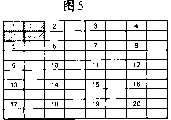
图5是表示识别区域的扫描顺序的图。FIG. 5 is a diagram showing the scanning order of the recognition area.
图6是表示识别区域的扫描顺序的图。FIG. 6 is a diagram showing the scanning order of the recognition area.
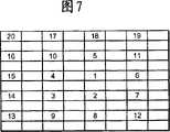
图7是表示识别区域的扫描顺序的图。FIG. 7 is a diagram showing the scanning order of the recognition area.
图8是表示本发明的实施例2的图像识别装置的结构图。Fig. 8 is a configuration diagram showing an image recognition device according to
图9是表示本发明的实施例2的图像识别装置的动作的流程图。Fig. 9 is a flowchart showing the operation of the image recognition device according to the second embodiment of the present invention.
图10是表示图像数据的像素值的图。FIG. 10 is a diagram showing pixel values of image data.
图11是表示积分图像数据的图。FIG. 11 is a diagram showing integrated image data.
图12是表示对图像数据设置了识别区域的状态的图。FIG. 12 is a diagram showing a state where a recognition area is set for image data.
具体实施方式Detailed ways
实施例1Example 1
图1是用于实施本发明的实施例1的图像识别装置的结构图。在图1中,将通过对来自未图示的摄像装置的视频信号进行数字化而输入到输入部件1的图像数据转送到特征量计算部件2和标准化处理部件4。特征量计算部件2针对每个帧计算出其图像数据的全部像素的平均值和分布等特征量,并发送到标准化模式选择部件3。在标准化模式记录部件8中记录有多种标准化模式的查找表,标准化模式选择部件3参照记录在标准化模式记录部件8中的查找表,选择与特征量计算部件2计算出的特征量对应的标准化模式,并展开到存储器(未图示)中。标准化处理部件4使用该被展开到存储器内的标准化模式,对图像数据进行标准化。扫描模式设置部件6对每个帧设置扫描模式记录部件9内的扫描模式。扫描部件5根据由扫描模式设置部件6设置了的扫描模式,在扫描部件5中扫描识别区域。对照部件7对由扫描部件5扫描了的识别区域内的图像数据和识别对象的模型数据进行对照,输出对照结果。FIG. 1 is a block diagram of an image recognition device for implementing
接着,使用图2说明这样构成的图像识别装置的动作。图2是表示本实施例1的图像识别装置的动作的流程图。首先,向输入部件1输入每个帧的图像数据(st101)。将输入到输入部件1的帧的图像数据转送到特征量计算部件2和标准化处理部件4(st102)。特征量计算部件2对每个帧计算出转送了的图像数据的特征量(st103)。在此,说明作为特征量计算出图像数据内的全部像素值的平均值的情况,但特征量也可以是像素值的分布、直方图、最小值、最大值等。另外,在此用0~255的8比特表现图像数据的各像素值。进而,用INT型定义作为特征量的像素的平均值,对小数点以下进行舍入而取得0~255的整数值。Next, the operation of the image recognition device configured in this way will be described using FIG. 2 . FIG. 2 is a flowchart showing the operation of the image recognition device of the first embodiment. First, image data of each frame is input to the input section 1 (st101). The image data of the frame input to the
标准化模式选择部件3参照记录在标准化模式记录部件8中的查找表,选择与由特征量计算部件2计算出的特征量对应的标准化模式,并展开到存储器中(st104)。在图3中表示在设记录在标准化模式记录部件8中的特征量为像素的平均值时的查找表。在图3中,在查找表100中与0~255的特征量对应地记录有多种标准化模式。通过组合多种函数能够构成各标准化模式,例如组合一次函数、二次函数、三角函数、指数函数等,预先构成与特征量对应的模式。例如在由特征量计算部件2计算出的特征量是0的情况下,选择标准化模式101,在是252的情况下选择标准化模式102,在是255的情况下选择标准化模式103,并展开到存储器中。在标准化模式101、102、103中,横轴表示标准化处理前的像素值,纵轴表示标准化处理后的像素值。The normalization
另外,在作为特征量使用了像素的分布值的情况下,也可以与上述的平均值的情况一样,作成具有与各分布值对应的标准化模式的查找表。Also, when distribution values of pixels are used as feature quantities, a lookup table having a normalization pattern corresponding to each distribution value may be created similarly to the case of the above-mentioned average value.
接着,标准化处理部件4通过使用由标准化模式选择部件3选择并展开到存储器中的标准化模式,对图像数据的像素值进行变换,而进行标准化处理(st105)。这样,通过预先将作为与图像数据的特征量对应地对像素值进行了变换的结果的标准化模式,作为查找表记录在标准化模式记录部件8中,在进行标准化处理时就不需要进行计算处理了。另外,标准化模式选择部件3与特征量对应地选择标准化模式,因此能够灵活地对应摄影时的照明变化。Next, the
接着,扫描模式设置部件6依照记录在扫描模式记录部件9中的那样设置扫描模式(st106)。扫描部件5根据由扫描模式设置部件6设置了的扫描模式,对识别区域进行扫描(st107)。Next, the scanning
在此,说明识别区域的扫描的方法。如图4所示,在扫描模式记录部件9中,记录有使用扫描模式个数、扫描模式顺序、扫描模式。扫描模式个数表示所使用的扫描模式的个数,扫描模式顺序表示所使用的扫描模式的顺序。另外,扫描模式由模式ID、座标数、座标表构成。模式ID表示用于确定该扫描模式的ID,座标数表示适用于1帧的图像数据的识别区域的个数。另外,座标表只包含座标个数的表示图像数据内的x座标、y座标的座标值,各座标值表示图像数据内的识别区域的位置。Here, a method of scanning the recognition area will be described. As shown in FIG. 4 , in the scan
扫描部件5针对标准化处理了的图像数据,使用具有由扫描模式顺序指定的模式ID的扫描模式,扫描识别区域。在此,为了说明的方便,说明使用扫描模式个数为3,检测模式顺序为1、2、3的顺序,各帧的图像数据的大小为横8×纵10的80个像素,识别区域的大小为横2×纵2的4个像素的情况,但可以将它们设置为适当的值。The
由于先头的检测模式顺序是1,所以扫描部件5针对最初输入的帧的图像数据,根据模式ID为1的扫描模式21进行识别区域的扫描。另外,针对接着输入的帧的图像数据,根据模式ID为2的扫描模式22进行识别区域的扫描,进而针对其后输入的帧的图像数据,根据模式ID为3的扫描模式23进行识别区域的扫描。这样,以在扫描模式顺序中指定的顺序,根据各扫描模式进行识别区域的扫描。Since the first detection pattern sequence is 1, the
图5是表示根据扫描模式21进行识别区域的扫描时的扫描顺序的图。图5的各模块表示图像数据内的像素。附加了数字的像素表示由座标表内的座标值指定。另外,数字的顺序与座标表内的座标值的顺序对应。即,扫描模式数据21内的座标表的最初的座标值(x1-1,y1-1)是附加了1的像素的图像数据内的座标,下一个座标值(x1-2,y1-2)是附加了2的像素的图像数据内的座标。现在,扫描模式21的座标个数是20,因此向图像数据内的像素附加1到20的数字。FIG. 5 is a diagram showing a scanning sequence when scanning the recognition area according to the
接着,扫描部件5以记录在座标表中的座标值的顺序进行识别区域的扫描。这时,各座标值表示识别区域的左上端的座标。最初,在将图5中的1的位置作为识别区域的左上端的用斜线所示的位置处设置识别区域。接着,在将2的位置作为识别区域的左上端的位置处设置识别区域。循环这些动作共座标个数的次数,在此为20次,进行识别区域的扫描。Next, the
另外,针对下一个帧的图像数据,扫描部件5根据扫描模式22循环进行同样的动作,进行识别区域的扫描。在图6中表示根据扫描模式22扫描识别区域时的扫描顺序。如从图6可知的那样,扫描模式22的座标个数为16,座标表内的各座标值(x2-1,y2-1)~(x2-16,y2-16)是逐个像素地将扫描模式21的座标表内的座标值(x1-1,y1-1)~(x1-16,y1-16)向下方移动了的座标值。In addition, with respect to the image data of the next frame, the
这样,通过针对连续的帧根据不同的扫描模式进行识别区域的扫描,能够用其他的扫描模式对在各扫描模式中间隔抽取出的像素进行补足,能够提高识别精度。In this way, by performing scanning of the recognition area in accordance with different scan patterns for consecutive frames, the pixels extracted in each scan pattern can be supplemented with other scan patterns, and the recognition accuracy can be improved.
另外,如果将例如如图7所示那样从图像数据的中心开始螺旋状地扫描识别区域那样的扫描模式记录在扫描模式记录部件9中,则能够提供对识别对象存在于图像的中心的可能性高的情况有效的识别区域的扫描顺序。这样,用户能够与目的对应地设置识别区域的扫描顺序。In addition, if a scan pattern that scans the identification area spirally from the center of the image data as shown in FIG. A high case effectively identifies the scan order of the region. In this way, the user can set the scanning order of the recognition areas corresponding to the purpose.
另外,在此说明了预先设置了扫描模式顺序的情况,但也可以不特别地决定这些顺序。即,也可以构成为随机地选择记录在扫描模式记录部件9中的扫描模式。In addition, the case where the order of the scan patterns is set in advance has been described here, but these orders may not be particularly determined. That is, the scan pattern recorded in the scan
接着,对照部件7对扫描部件5扫描的识别区域内的图像数据和识别对象的模型数据进行对照(st108)。该对照的方法例如有求出图像相关性的方法或以下的方法。Next, the
例如抽出学习了物体的特征后的数据作为被称为矩形特征(Rectangle Feature:Rf)的特征量。使用组合了矩形特征的被称为分类器(Classifier)的判别函数来表现物体的特征。具体地说,如公式(1)所示那样,与各矩形特征的值(Rf(i))是否超过了阈值(th)对应地赋予加权(pv或nv)。接着,定义公式(2)所示那样的全部的矩形特征的加权的总和(Cls),如公式(3)所示那样,在该总和超过了某阈值(th2)的情况下,将其判断为识别对象(obiect),在没有超过的情况下,判断为非识别对象(nonobject)。将该判断结果作为对照结果输出(st109)。For example, data obtained by learning the features of an object is extracted as a feature quantity called a rectangle feature (Rectangle Feature: Rf). Object features are expressed using a discriminant function called a classifier that combines rectangular features. Specifically, as shown in formula (1), weighting (pv or nv) is given according to whether the value (Rf(i)) of each rectangular feature exceeds a threshold value (th). Next, the weighted sum (Cls) of all rectangular features as shown in formula (2) is defined, and when the sum exceeds a certain threshold (th2) as shown in formula (3), it is judged as If the recognition object (obiect) does not exceed, it is judged as a non-recognition object (nonobject). This judgment result is output as a collation result (st109).
公式(1)Formula 1)
公式(2)Formula (2)
公式(3)Formula (3)
在本实施例1的图像识别装置中,说明了用0~255的8比特表现输入的图像数据的各像素值的灰度等级(gray scale)的图像,但也可以是用R、G、B分别为8比特的合计24比特表现各像素值的全彩色等的图像。在该情况下,在st103中作为图像数据的特征量求出像素值的平均值的情况下,求出每个颜色的像素值的平均值,在st104中选择标准化模式时,通过与各色的特征量对应地选择不同种类的标准化模式,能够起到同样的效果。In the image recognition device of the
另外,记录在标准化模式记录部件8中的查找表的标准化模式也可以是对于全部的特征量的每个都不同的标准化模式,根据特征量的范围,也可以是相同的标准化模式。这样,通过使用在某种程度的特征量的范围内相同的标准化模式,能够削减标准化模式记录部件8的存储器容量。In addition, the normalization pattern of the lookup table recorded in the normalization
实施例2Example 2
图8是用于实施本发明的实施例2的图像识别装置的结构图,向与图1对应的部分附加相同的编号。在图8中,输入到输入部件1的图像数据被转送到扫描部件5和积分图像数据计算部件10。扫描模式设置部件6针对每个帧设置扫描模式记录部件9内的扫描模式,扫描部件5根据所设置的扫描模式,扫描识别区域。另外,积分图像数据计算部件10计算每个帧的图像数据的积分图像数据。特征量计算部件2使用该积分图像数据,计算识别区域内的图像数据的特征量。标准化模式选择部件3参照记录在标准化模式记录部件8中的查找表,选择与由特征量计算部件2计算出的特征量对应的标准化模式并展开到存储器(在图中未表示)中。标准化处理部件4使用该被展开在存储器内的标准化模式,对识别区域内的图像数据进行标准化。对照部件7对该标准化了的图像数据和识别对象的模型数据进行对照,输出对照结果。FIG. 8 is a configuration diagram of an image recognition apparatus according to
接着,使用图9说明这样构成的图像识别装置的动作。图9是表示本实施例2的图像识别装置的动作的流程图。首先,向输入部件1输入每个帧的图像数据(st201)。输入到输入部件1的图像数据被转送到扫描部件5和积分图像数据计算部件10(st202)。扫描模式设置部件6与st106一样地(参照图2,下同),根据记录在扫描模式记录部件9中的扫描模式,设置扫描模式(st203)。另外,与st107一样地,扫描部件5根据所设置的扫描模式,扫描识别区域(st204)。Next, the operation of the image recognition device configured in this way will be described using FIG. 9 . FIG. 9 is a flowchart showing the operation of the image recognition device according to the second embodiment. First, image data of each frame is input to the input section 1 (st201). The image data input to the
另一方面,积分图像数据计算部件10计算从输入部件1转送的图像数据的积分图像数据(st205)。在此,积分图像数据是针对图像数据在水平垂直方向上求出了像素值的累计的图像数据。在设原始的图像数据的像素值为I(x,y)时,用公式(4)表示积分图像数据I’(x,y)。On the other hand, the integral image
公式(4)Formula (4)
例如,在原始的图像数据是具有图10所示那样的像素值的图像数据的情况下,该图像数据的积分图像数据如图11所示。For example, when the original image data is image data having pixel values as shown in FIG. 10 , integrated image data of the image data is as shown in FIG. 11 .
接着,特征量计算部件2使用积分图像数据,计算出识别区域内的图像数据的特征量(st206)。在此,在设特征量为像素值的平均的情况下,需要计算出识别区域内的像素值的和。现在,如果将识别部件5识别的识别区域设置为图12所示那样附加了斜线的区域,设A、B、C、D的图像数据内的座标分别为(xA,yA)、(xB,yB)、(xC,yC)、(xD,yD),则可以根据公式(5)求出识别区域内的像素值的和S。Next, the feature
公式(5)Formula (5)
S=I′(xA,yA)+I′(xD,yD)-(I′(xB,yB)+I′(xC,yC))S=I'(xA , yA )+I'(xD , yD )-(I'(xB , yB )+I'(xC , yC ))
这样,通过使用积分图像数据,容易地求出任意的矩形区域的像素值的和,能够减少特征量计算部件2中的计算量。In this way, by using the integrated image data, the sum of the pixel values of an arbitrary rectangular area can be easily obtained, thereby reducing the amount of calculation in the feature
接着,与st104一样地,标准化模式选择部件3参照记录在标准化模式记录部件8中的查找表,选择与由特征量计算部件2计算出的特征量对应的标准化模式,并展开到存储器中(st207)。标准化处理部件4针对识别区域内的图像数据,通过与st105一样的操作,进行标准化处理(st208)。然后,对照部件7通过与st108、st109一样的步骤,进行与模型数据的对照(st209),输出对照结果(st210)。Next, as in st104, the normalization
在本实施例2的图像识别装置中,由于以识别区域为单位进行图像数据的标准化处理,所以对局部的照明变化的耐性变强,起到能够提高识别精度的效果。In the image recognition device according to the second embodiment, since the image data is normalized in units of recognition regions, the resistance to local illumination changes is increased, and the recognition accuracy can be improved.
另外,在本实施例中,说明了作为特征量使用了图像数据的像素值的平均值的情况,但作为特征量也可以是像素值的分布。在该情况下,也可以在st205中求出积分图像数据的同时,在将图像数据的各像素值进行了平方的基础上,求出在水平垂直方向上求出了像素值的累计值后的平方积分图像数据,使用积分图像数据和平方积分图像数据,计算出识别区域内的像素值的分布值v。可以根据公式(6)计算出分布值v。In addition, in this embodiment, the case where the average value of the pixel values of the image data is used as the feature quantity has been described, but the feature quantity may be a distribution of pixel values. In this case, while calculating the integrated image data in st205, the pixel values of the image data are squared, and the integrated value of the pixel values obtained in the horizontal and vertical directions may be obtained. In the square integral image data, the distribution value v of the pixel values in the recognition area is calculated using the integral image data and the square integral image data. The distribution value v can be calculated according to formula (6).
公式(6)Formula (6)
在公式(6)中,In formula (6),
SS:识别区域内的平方积分图像数据的和SS: sum of squared integral image data within the recognition area
S:识别区域内的积分图像数据的和S: sum of integral image data within the recognition area
n:识别区域内的像素的总数。n: the total number of pixels in the recognition area.
这样,即使在作为特征量使用像素值的分布值的情况下,也能够减轻特征量计算部件2中的计算量。In this way, even in the case where distribution values of pixel values are used as feature quantities, the amount of calculation in the feature
Claims (6)
Translated fromChineseApplications Claiming Priority (5)
| Application Number | Priority Date | Filing Date | Title |
|---|---|---|---|
| JP2005292525 | 2005-10-05 | ||
| JP2005292525 | 2005-10-05 | ||
| JP2005-292525 | 2005-10-05 | ||
| JP2006024086 | 2006-02-01 | ||
| JP2006-024086 | 2006-02-01 |
Publications (2)
| Publication Number | Publication Date |
|---|---|
| CN1945598Atrue CN1945598A (en) | 2007-04-11 |
| CN100419781C CN100419781C (en) | 2008-09-17 |
Family
ID=38044997
Family Applications (1)
| Application Number | Title | Priority Date | Filing Date |
|---|---|---|---|
| CNB2006101415553AExpired - Fee RelatedCN100419781C (en) | 2005-10-05 | 2006-09-28 | Image recognition device |
Country Status (1)
| Country | Link |
|---|---|
| CN (1) | CN100419781C (en) |
Cited By (2)
| Publication number | Priority date | Publication date | Assignee | Title |
|---|---|---|---|---|
| CN101571698B (en)* | 2008-05-02 | 2011-12-07 | 夏普株式会社 | Method for matching images, image matching device, image data output apparatus, and recording medium |
| CN114219839A (en)* | 2021-12-24 | 2022-03-22 | 欧波同科技产业有限公司 | Frame image position calculation method based on matrix filling algorithm |
Family Cites Families (6)
| Publication number | Priority date | Publication date | Assignee | Title |
|---|---|---|---|---|
| JP4091174B2 (en)* | 1998-08-11 | 2008-05-28 | 株式会社東芝 | Image processing apparatus and image processing method |
| JP3529640B2 (en)* | 1998-09-17 | 2004-05-24 | 松下電器産業株式会社 | Image data recognition method and apparatus |
| JP2001006599A (en)* | 1999-06-22 | 2001-01-12 | Jeol Ltd | Electron beam control method in electron beam device |
| JP3712234B2 (en)* | 2002-03-19 | 2005-11-02 | 株式会社日立製作所 | Region of interest extraction method and image processing server |
| JP4521747B2 (en)* | 2002-12-13 | 2010-08-11 | シャープ株式会社 | Object information processing apparatus, image processing system, game apparatus, and image processing method |
| JP4603807B2 (en)* | 2004-03-10 | 2010-12-22 | 富士通株式会社 | Character recognition device, character recognition method, medium processing method, character recognition program, and computer-readable recording medium on which character recognition program is recorded |
- 2006
- 2006-09-28CNCNB2006101415553Apatent/CN100419781C/ennot_activeExpired - Fee Related
Cited By (2)
| Publication number | Priority date | Publication date | Assignee | Title |
|---|---|---|---|---|
| CN101571698B (en)* | 2008-05-02 | 2011-12-07 | 夏普株式会社 | Method for matching images, image matching device, image data output apparatus, and recording medium |
| CN114219839A (en)* | 2021-12-24 | 2022-03-22 | 欧波同科技产业有限公司 | Frame image position calculation method based on matrix filling algorithm |
Also Published As
| Publication number | Publication date |
|---|---|
| CN100419781C (en) | 2008-09-17 |
Similar Documents
| Publication | Publication Date | Title |
|---|---|---|
| JP4670664B2 (en) | Image recognition device | |
| JP4771906B2 (en) | Method for classifying images with respect to JPEG compression history | |
| US6985631B2 (en) | Systems and methods for automatically detecting a corner in a digitally captured image | |
| KR101795823B1 (en) | Text enhancement of a textual image undergoing optical character recognition | |
| Khanna et al. | Forensic techniques for classifying scanner, computer generated and digital camera images | |
| JP6139396B2 (en) | Method and program for compressing binary image representing document | |
| KR100874561B1 (en) | Image Processing Apparatus and Method | |
| CN101228550A (en) | Binarization of images | |
| Khanna et al. | Scanner identification using feature-based processing and analysis | |
| EP2605186B1 (en) | Method and apparatus for recognizing a character based on a photographed image | |
| CN103177249A (en) | Image processing apparatus and image processing method | |
| CN101042735A (en) | Image binarization method and device | |
| JP2011128990A (en) | Image processor and image processing method | |
| CN102737240B (en) | Method of analyzing digital document images | |
| CN102750686B (en) | Super-resolution file image restoration processing method based on learning | |
| JP2005521116A (en) | Device for detecting edges in image blocks | |
| US9332154B2 (en) | Image binarization using dynamic sub-image division | |
| CN100433047C (en) | Device and method for detecting blurring of image | |
| Lins et al. | Doceng'2020 time-quality competition on binarizing photographed documents | |
| US9167129B1 (en) | Method and apparatus for segmenting image into halftone and non-halftone regions | |
| CN1237485C (en) | Method for covering face of news interviewee using quick face detection | |
| CN1945598A (en) | Image recognition device | |
| CN1797428A (en) | Method and device for self-adaptive binary state of text, and storage medium | |
| CN1920853A (en) | Systems and methods for content identification | |
| CN1941838A (en) | File and picture binary coding method |
Legal Events
| Date | Code | Title | Description |
|---|---|---|---|
| C06 | Publication | ||
| PB01 | Publication | ||
| C10 | Entry into substantive examination | ||
| SE01 | Entry into force of request for substantive examination | ||
| C14 | Grant of patent or utility model | ||
| GR01 | Patent grant | ||
| C17 | Cessation of patent right | ||
| CF01 | Termination of patent right due to non-payment of annual fee | Granted publication date:20080917 Termination date:20120928 |