CN1934485A - Image display device - Google Patents
Image display deviceDownload PDFInfo
- Publication number
- CN1934485A CN1934485ACNA2005800090613ACN200580009061ACN1934485ACN 1934485 ACN1934485 ACN 1934485ACN A2005800090613 ACNA2005800090613 ACN A2005800090613ACN 200580009061 ACN200580009061 ACN 200580009061ACN 1934485 ACN1934485 ACN 1934485A
- Authority
- CN
- China
- Prior art keywords
- display device
- eye
- user
- image
- image display
- Prior art date
- Legal status (The legal status is an assumption and is not a legal conclusion. Google has not performed a legal analysis and makes no representation as to the accuracy of the status listed.)
- Granted
Links
Images


Classifications
- G—PHYSICS
- G02—OPTICS
- G02B—OPTICAL ELEMENTS, SYSTEMS OR APPARATUS
- G02B27/00—Optical systems or apparatus not provided for by any of the groups G02B1/00 - G02B26/00, G02B30/00
- G02B27/01—Head-up displays
- G02B27/017—Head mounted
- G02B27/0172—Head mounted characterised by optical features
- G—PHYSICS
- G02—OPTICS
- G02B—OPTICAL ELEMENTS, SYSTEMS OR APPARATUS
- G02B27/00—Optical systems or apparatus not provided for by any of the groups G02B1/00 - G02B26/00, G02B30/00
- G02B27/02—Viewing or reading apparatus
- G—PHYSICS
- G02—OPTICS
- G02B—OPTICAL ELEMENTS, SYSTEMS OR APPARATUS
- G02B27/00—Optical systems or apparatus not provided for by any of the groups G02B1/00 - G02B26/00, G02B30/00
- G02B27/01—Head-up displays
- G02B27/017—Head mounted
- G02B27/0176—Head mounted characterised by mechanical features
- H—ELECTRICITY
- H04—ELECTRIC COMMUNICATION TECHNIQUE
- H04N—PICTORIAL COMMUNICATION, e.g. TELEVISION
- H04N5/00—Details of television systems
- H04N5/74—Projection arrangements for image reproduction, e.g. using eidophor
- G—PHYSICS
- G02—OPTICS
- G02B—OPTICAL ELEMENTS, SYSTEMS OR APPARATUS
- G02B27/00—Optical systems or apparatus not provided for by any of the groups G02B1/00 - G02B26/00, G02B30/00
- G02B27/01—Head-up displays
- G02B27/0101—Head-up displays characterised by optical features
- G02B2027/0123—Head-up displays characterised by optical features comprising devices increasing the field of view
- G—PHYSICS
- G02—OPTICS
- G02B—OPTICAL ELEMENTS, SYSTEMS OR APPARATUS
- G02B27/00—Optical systems or apparatus not provided for by any of the groups G02B1/00 - G02B26/00, G02B30/00
- G02B27/01—Head-up displays
- G02B27/0101—Head-up displays characterised by optical features
- G02B2027/0129—Head-up displays characterised by optical features comprising devices for correcting parallax
- G—PHYSICS
- G02—OPTICS
- G02B—OPTICAL ELEMENTS, SYSTEMS OR APPARATUS
- G02B27/00—Optical systems or apparatus not provided for by any of the groups G02B1/00 - G02B26/00, G02B30/00
- G02B27/01—Head-up displays
- G02B27/0101—Head-up displays characterised by optical features
- G02B2027/0132—Head-up displays characterised by optical features comprising binocular systems
- G—PHYSICS
- G02—OPTICS
- G02B—OPTICAL ELEMENTS, SYSTEMS OR APPARATUS
- G02B27/00—Optical systems or apparatus not provided for by any of the groups G02B1/00 - G02B26/00, G02B30/00
- G02B27/01—Head-up displays
- G02B27/017—Head mounted
- G02B2027/0178—Eyeglass type
- H—ELECTRICITY
- H04—ELECTRIC COMMUNICATION TECHNIQUE
- H04N—PICTORIAL COMMUNICATION, e.g. TELEVISION
- H04N5/00—Details of television systems
- H04N5/74—Projection arrangements for image reproduction, e.g. using eidophor
- H04N5/7475—Constructional details of television projection apparatus
- H04N5/7491—Constructional details of television projection apparatus of head mounted projectors
Landscapes
- Physics & Mathematics (AREA)
- General Physics & Mathematics (AREA)
- Optics & Photonics (AREA)
- Engineering & Computer Science (AREA)
- Multimedia (AREA)
- Signal Processing (AREA)
Abstract
Description
Translated fromChinese技术领域technical field
本发明涉及一种可安装在头部等身体部位上使用的小型图像显示装置。The invention relates to a small image display device which can be installed on the head and other body parts.
背景技术Background technique
安装在头部等身体部位上使用的、在使用者眼前显示图像的头戴显示器(HMD)运用在以虚拟现实为首的各种领域中。HMD通常通过遮断外来光来只显示图像,一般形成为护目镜形状或大型眼镜的镜架形状。如果使用HMD,那么无论使用者面向何方都可以看见图像,相反,无法看见外界。Head-mounted displays (HMDs), which are mounted on parts of the body such as the head and display images in front of the user's eyes, are used in various fields including virtual reality. HMDs generally display only images by blocking external light, and are generally formed in the shape of goggles or frames of large glasses. If an HMD is used, the image can be seen no matter where the user is facing, on the contrary, the outside world cannot be seen.
近年来,公开了一种图像显示在视野的一部分、外界和图像都能看见的小型图像显示装置。In recent years, there has been disclosed a compact image display device in which an image is displayed in a part of the field of view, and the outside world and the image can be seen.
这种类型的图像显示装置举例有日本专利特开平7-209600号公报公开的装置。该图像显示装置构成为,液晶显示装置(LCD)、反射镜、目镜等收容在一个框体内,而且在该框体上还安装有夹子,并用夹子安装到眼镜或太阳镜的框架上。框体安装在眼镜的左右透镜中的任一者的上部外侧附近,在LCD中显示的图像可通过反射镜、目镜以及眼镜的透镜从斜上方传到使用者的一只眼睛中。An example of this type of image display device is disclosed in Japanese Patent Application Laid-Open No. 7-209600. The image display device is configured such that a liquid crystal display (LCD), a reflector, an eyepiece, etc. are housed in a frame, and a clip is attached to the frame, and the clip is attached to a frame of glasses or sunglasses. The frame is installed near the upper outer side of any one of the left and right lenses of the glasses, and the image displayed on the LCD can be transmitted to one eye of the user obliquely from above through the reflector, the eyepiece and the lens of the glasses.
由于这种类型的图像显示装置可以通过视线的移动来选择是看外界还是看图像,故可以在日常生活中的场所使用,作为使用场所不用特别考虑是室内还是室外,在这点上价值很高。Since this type of image display device can choose whether to look at the outside world or look at the image through the movement of the line of sight, it can be used in places in daily life. As a place of use, it does not need to consider whether it is indoors or outdoors, and it is very valuable in this regard. .
因此,若是这种图像显示装置,则可使声音再生,可应用于很大地改变了年轻人的生活方式的便携式耳机立体声系统的影像版这类的用途。Therefore, such an image display device can reproduce sound, and can be applied to applications such as a video version of a portable earphone stereo system that has greatly changed the lifestyle of young people.
然而,在这种类型的图像显示装置中,确保容易看见图像是极其重要的。However, in this type of image display device, it is extremely important to ensure easy viewing of images.
然而,由于脸形存在个人差,故也有可能存在图像显示装置和使用者的眼睛的位置关系不合适、使得使用者无法轻松地观看图像的情况。However, due to individual differences in face shapes, the positional relationship between the image display device and the user's eyes may not be appropriate, making it difficult for the user to view images easily.
为了解决上述问题,本发明的课题是对将图像显示在视野一部分的图像显示装置进行改进以使图像容易观看。In order to solve the above problems, an object of the present invention is to improve an image display device that displays an image in a part of the field of view so that the image is easy to see.
发明的公开disclosure of invention
为了解决上述问题,本申请的发明人提出了下面两个发明。In order to solve the above-mentioned problems, the inventors of the present application proposed the following two inventions.
本申请的第一发明是包括可安装在使用者身体上的本体、使用时安装在使用者身体上使用的图像显示装置。The first invention of the present application is an image display device that includes a main body that can be attached to the user's body and is used while being attached to the user's body.
并且,在该图像显示装置的所述本体上设有显示构件,在所述图像显示装置使用时,该显示构件位于使用者的一只眼睛的前面,通过将规定图像的图像光引入所述一只眼睛,以存在于作为该一只眼睛的视野一部分的显示范围内的状态,用该一只眼睛观看所述图像,而且,所述显示构件以可在所述本体安装在使用者身体上时的左右方向上移动的形态设在所述本体上,而且,将所述图像显示装置安装在身体上的使用者至少通过移动视线便可例如用两只眼睛观看外界。In addition, a display member is provided on the body of the image display device, and when the image display device is in use, the display member is located in front of one eye of the user, and by introducing image light of a prescribed image into the one eye one eye to view the image with the one eye in a state of being present within the display range that is a part of the visual field of the one eye, and the display member can be configured to The form that moves in the left and right directions is provided on the body, and the user who mounts the image display device on the body can see the outside world with both eyes at least by moving the line of sight.
若是这种图像显示装置,则显示构件可以在左右方向上移动,故可以调整显示构件的位置,使显示构件和使用者的眼睛的位置关系变得合适,从而使得使用者可以轻松地观看图像。In this image display device, the display member can move in the left and right directions, so the position of the display member can be adjusted to make the positional relationship between the display member and the user's eyes appropriate, so that the user can easily view the image.
第一发明的图像显示装置中的显示构件可以是一个,也可以是两个。如果是一个显示构件,则容易实现低成本化。另外,如果是两个显示构件,则更容易增加观看图像时身临其境的感觉。In the image display device of the first invention, there may be one or two display members. If it is a display member, cost reduction can be easily achieved. In addition, if there are two display members, it is easier to increase the immersive feeling when viewing images.
如果是两个显示构件,则至少其中的一个以可在所述本体安装在使用者身体上时的左右方向上移动的形态设在所述本体上即可。当然,也可以是两个都以可在所述本体安装在使用者身体上时的左右方向上移动的形态设在所述本体上。In the case of two display members, at least one of them may be provided on the main body so as to be movable in the left and right directions when the main body is mounted on the user's body. Of course, both may be provided on the body in a form that can move in the left and right directions when the body is mounted on the user's body.
显示构件为两个时的第一发明的图像显示装置,包括可安装在使用者身体上的本体,且使用时安装在使用者身体上使用,在所述本体上设有第一显示构件和第二显示构件,在所述图像显示装置使用时,该第一显示构件位于使用者的一只眼睛的前面,通过将规定图像的图像光引入所述一只眼睛,以存在于作为该一只眼睛的视野一部分的显示范围内的状态,用该一只眼睛观看所述图像,另一方面,在所述图像显示装置使用时,该第二显示构件位于使用者的另一只眼睛的前面,通过将规定图像的图像光引入所述另一只眼睛,以存在于作为该另一只眼睛的视野一部分的显示范围内的状态,用该另一只眼睛观看所述图像,而且,所述第一显示构件和所述第二显示构件都以可在所述本体安装在使用者身体上时的左右方向上移动的形态设在所述本体上,而且,将所述图像显示装置安装在身体上的使用者至少通过移动视线便可例如用两只眼睛观看外界。When there are two display components, the image display device of the first invention includes a main body that can be installed on the user's body, and is installed on the user's body for use, and the first display component and the second display component are arranged on the main body. Two display members. When the image display device is in use, the first display member is located in front of one eye of the user, and by introducing image light of a prescribed image into the one eye, it exists as the one eye. In a state within the display range of a part of the visual field, the image is viewed with the one eye; on the other hand, when the image display device is in use, the second display member is located in front of the other eye of the user, through introducing image light of a prescribed image into the other eye, viewing the image with the other eye in a state existing within a display range that is a part of the visual field of the other eye, and the first Both the display member and the second display member are provided on the body so as to be movable in the left and right directions when the body is mounted on the user's body, and the process of mounting the image display device on the body The user can see the outside world, for example, with both eyes, at least by moving the line of sight.
另外,用来使第一发明中的显示构件在所述本体安装在使用者身体上时的左右方向上移动的具体结构的详细内容不作限定。是两个显示构件时,对于用来使显示构件在所述本体安装在使用者身体上时的左右方向上移动的结构,既可以两个显示构件相同,也可以不同。In addition, the details of the specific structure for moving the display member in the first invention in the left and right directions when the main body is mounted on the user's body are not limited. In the case of two display members, the structures for moving the display members in the left and right directions when the main body is attached to the user's body may be the same or different.
在第一发明中,在显示构件是一个时,也可在所述本体上设有遮蔽构件,在所述图像显示装置使用时,该遮蔽构件位于使用者的另一只眼睛的前面,使从该另一只眼睛的视野中的作为与所述显示范围大致对应的范围或包含该范围在内的更大范围的遮蔽范围进入到所述另一只眼睛的光弱于从所述显示范围进入到所述一只眼睛的光。In the first invention, when there is only one display member, a shielding member may be provided on the main body, and when the image display device is in use, the shielding member is positioned in front of the other eye of the user so that the user can see In the field of view of the other eye, the light entering the other eye is weaker than the light entering the other eye from the shielding range approximately corresponding to the display range or a larger range including the range. light to the one eye.
遮蔽构件起着消除如下所述的视野斗争问题的作用。The shielding member acts to eliminate the field of view struggle problem as described below.
在具有一个显示构件的图像显示装置中,在用单只眼睛看显示器时,在另一只眼睛中可以看见周围的景色。这种情况下,会产生视野斗争问题。In an image display device having one display member, while looking at the display with one eye, the surrounding scenery can be seen in the other eye. In this case, a visual field struggle problem arises.
所谓视野斗争,是指在来自右眼和左眼的信息中,只有其中一方留在了意识中的现象。虽然来自右眼和左眼的信息一般多少有些差异(例如,两眼的视差),但具有很多共同点。这种情况下,大脑从两种信息中选择一种,将其认为是看到的“内容”。与此相对,在共同点少、相互差异大的信息分别进入右眼和左眼时,大脑便不能很好地处理这些信息。这种情况下,有时大脑会进行处理,以一种信息为优先而只看到这种信息。这种情况下,认为可以看到基于大脑优先选择的信息的图像以及景色,但并不认为可以看到基于大脑未优先选择的信息的图像以及景色。The so-called vision struggle refers to the phenomenon that only one of the information from the right eye and the left eye remains in consciousness. Although the information from the right eye and the left eye is generally somewhat different (eg, the disparity of the two eyes), they have a lot in common. In this case, the brain chooses one of two types of information and considers it to be "what" it sees. In contrast, when information with little in common and large differences enters the right eye and left eye respectively, the brain cannot process the information well. In this case, sometimes the brain processes and prioritizes one kind of information and only sees that kind of information. In this case, it is considered that images and scenery based on information preferentially selected by the brain can be seen, but it is not considered that images and scenery based on information not preferentially selected by the brain can be viewed.
这种视野斗争在如上所述的图像显示装置中显著地发生。如果发生视野斗争,那么认为可以看见显示器的情况和认为可以看见景色的情况便会交替地发生。如果看不见显示器的情况频繁发生,那么作为图像显示装置就失去了作用,另外,即使显示器勉强可以看见,如果视野斗争频繁发生,也会给使用者带来很大的疲劳。Such field-of-view struggles remarkably occur in the image display devices described above. If there is a field of view struggle, the situation where you think you can see the display alternates with the situation where you think you can see the view. If the monitor cannot be seen frequently, it will be useless as an image display device. In addition, even if the monitor can be barely seen, if the visual field struggle occurs frequently, it will cause great fatigue to the user.
如果有如上所述的遮蔽构件,那么通过用该遮蔽构件遮住在正前方安置有该遮蔽构件的一只眼睛的视野,可使该眼睛处于可以说是死亡状态,故会认为,大脑只能看到来自利用显示构件看到图像的一只眼睛的信息。由此,可以解决上述视野斗争的问题。If there is a shielding member as described above, by using the shielding member to block the field of vision of one eye on which the shielding member is placed directly in front, the eye can be put into a so-called dead state, so it will be considered that the brain can only Information is seen from the one eye that sees the image using the display member. Thereby, the above-mentioned problem of field of view struggle can be solved.
所述遮蔽构件能以可在所述本体安装在使用者身体上时的左右方向上移动的形态设置在所述本体上。只要所述遮蔽构件构成为:即使显示构件移动,在所述图像显示装置使用时也位于使用者的另一只眼睛的前面,且具有足够的大小,以使从该另一只眼睛的视野中的作为与所述显示范围大致对应的范围或包含该范围在内的更大范围的遮蔽范围进入到所述另一只眼睛的光弱于从所述显示范围进入到所述一只眼睛的光,则遮蔽构件也可以不用在左右方向上移动。The shielding member may be provided on the body in a form movable in a left and right direction when the body is mounted on a user's body. As long as the shielding member is configured so that even if the display member moves, it is positioned in front of the other eye of the user when the image display device is in use, and has a size sufficient to prevent the user from seeing the other eye. The light that enters the other eye is weaker than the light that enters the one eye from the display range as a range approximately corresponding to the display range or a larger range that includes the shade range , the shielding member does not need to move in the left and right directions.
本申请的第二发明是包括可安装在使用者身体上的本体、使用时安装在使用者身体上使用的图像显示装置。The second invention of the present application is an image display device that includes a main body that can be attached to the user's body and is used while being attached to the user's body.
并且,在该本体上设有显示构件,在所述图像显示装置使用时,该显示构件位于使用者的一只眼睛的前面,通过将规定图像的图像光引入所述一只眼睛,以存在于作为该一只眼睛的视野一部分的显示范围内的状态,用该一只眼睛观看所述图像,而且,所述显示构件以可在所述本体安装在使用者身体上时的上下方向上摆动的形态设在所述本体上,而且,将所述图像显示装置安装在身体上的使用者至少通过移动视线便可例如用两只眼睛观看外界。In addition, a display member is provided on the main body. When the image display device is in use, the display member is located in front of one eye of the user, and by introducing image light of a prescribed image into the one eye, the The image is viewed with the one eye as a state within the display range of a part of the field of view of the one eye, and the display member is swingable in an up and down direction when the main body is mounted on the user's body. The form is provided on the main body, and the user who mounts the image display device on the body can see the outside world, for example, with both eyes by at least moving the line of sight.
若是这种图像显示装置,则显示构件可以在上下方向上摆动,故可以调整显示构件的位置,使显示构件和使用者的眼睛的位置关系变得合适,从而使得使用者可以轻松地观看图像。In such an image display device, the display member can swing up and down, so the position of the display member can be adjusted to make the positional relationship between the display member and the user's eyes appropriate, so that the user can easily view the image.
第二发明的图像显示装置中的显示构件可以是一个,也可以是两个。如果是一个显示构件,则容易实现低成本化。另外,如果是两个显示构件,则更容易增加观看图像时身临其境的感觉。The number of display members in the image display device of the second invention may be one or two. If it is a display member, cost reduction can be easily achieved. In addition, if there are two display members, it is easier to increase the immersive feeling when viewing images.
如果是两个显示构件,则至少其中的一个以可在所述本体安装在使用者身体上时的上下方向上摆动的形态设在所述本体上即可。当然,也可以是两个都以可在所述本体安装在使用者身体上时的上下方向上摆动的形态设在所述本体上。If there are two display members, at least one of them may be provided on the main body so as to be swingable in the vertical direction when the main body is mounted on the user's body. Certainly, both may be provided on the body in a form that can swing in the up and down direction when the body is installed on the user's body.
显示构件为两个时的第二发明的图像显示装置,例如以包括可安装在使用者身体上的本体、使用时安装在使用者身体上使用的图像显示装置为基础,在所述本体上设有第一显示构件和第二显示构件,在所述图像显示装置使用时,该第一显示构件位于使用者的一只眼睛的前面,通过将规定图像的图像光引入所述一只眼睛,以存在于作为该一只眼睛的视野一部分的显示范围内的状态,用该一只眼睛观看所述图像,另一方面,在所述图像显示装置使用时,该第二显示构件位于使用者的另一只眼睛的前面,通过将规定图像的图像光引入所述另一只眼睛,以存在于作为该另一只眼睛的视野一部分的显示范围内的状态,用该另一只眼睛观看所述图像,而且,所述第一显示构件和所述第二显示构件都以可在所述本体安装在使用者身体上时的上下方向上摆动的形态设在所述本体上,而且,将所述图像显示装置安装在身体上的使用者至少通过移动视线便可例如用两只眼睛观看外界。The image display device of the second invention when there are two display members is, for example, based on an image display device that includes a main body that can be mounted on the user's body and is used while being mounted on the user's body. There are a first display member and a second display member, the first display member is positioned in front of one eye of a user when the image display device is in use, and by introducing image light of a prescribed image into the one eye, to Existing in the display range that is part of the field of view of the one eye, the image is viewed with the one eye, and on the other hand, when the image display device is used, the second display member is located on the other side of the user. In front of one eye, by introducing image light of a prescribed image into the other eye, the image is viewed with the other eye in a state of existing within a display range that is a part of the visual field of the other eye , and both the first display member and the second display member are provided on the body in a form that can swing up and down when the body is mounted on the user’s body, and the image The user with the display device mounted on the body can see the outside world with, for example, two eyes at least by moving the line of sight.
用来使第二发明中的显示构件在上下方向上摆动的具体结构不作限定。是两个显示构件时,对于用来使显示构件在所述本体安装在使用者身体上时的上下方向上摆动的结构,既可以两个显示构件相同,也可以不同。The specific structure for swinging the display member in the second invention in the up and down direction is not limited. In the case of two display members, the structures for swinging the display members in the vertical direction when the main body is mounted on the user's body may be the same or different.
用来使第二发明中的显示构件在上下方向上摆动的具体结构例如可以如下所述。A specific structure for swinging the display member in the second invention in the up and down direction may be as follows, for example.
可以采用如下结构:在所述本体上设有平行的上下两根棒体,且所述显示构件收容在盒子内,且在该盒子的顶面上设有与所述棒体中的上侧棒体嵌合的一个顶槽,而且在其底面上设有与所述棒体中的下侧棒体抵接的作为鞍状凸面的凸曲面,在所述两根棒体中的上侧棒体嵌合在所述顶槽内的状态下,使所述两根棒体中的下侧棒体沿所述凸曲面滑动,从而可以进行所述摆动。这种情况下,若在所述凸曲面的两端部上分别设有从该凸曲面突出的台阶部,则显示构件便不能摆动到超出所述两根棒体中的下侧棒体与所述台阶部中的任一方抵接的位置。这样,可以限制显示构件的摆动范围。The following structure can be adopted: the body is provided with two parallel upper and lower rods, and the display member is housed in a box, and the top surface of the box is provided with the upper rod of the rods. A top groove that fits the body, and a convex curved surface as a saddle-shaped convex surface abutting against the lower side of the rods is provided on its bottom surface, and the upper side of the two rods In a state fitted in the top groove, the lower rod body among the two rod bodies slides along the convex curved surface, so that the swing can be performed. In this case, if a step protruding from the convex curved surface is provided at both ends of the convex curved surface, the display member cannot swing beyond the lower rod body and the lower rod body of the two rod bodies. The position where any one of the above-mentioned stepped parts abuts. In this way, the swing range of the display member can be limited.
另外,可以采用如下结构:在所述本体上设有具有凸曲面的凸部,该凸曲面向所述图像显示装置安装在使用者身体上时的前方突出并构成规定球面的一部分,而且所述显示构件收容在盒子内,且在该盒子内设有具有凹曲面的凹部,该凹曲面是与所述凸曲面对应的曲面,且所述凸部和所述凹部利用磁力相互吸附,通过使所述凸部和所述凹部在嵌合的状态下相互吸附,可将所述显示构件固定在所述本体上,而且通过使所述凹部相对于所述凸部滑动,可进行所述摆动。这种情况下,凸部和凹部中的至少一方由磁体构成。在凸部和凹部中的一方为磁体时,另一方由可吸附到磁体上的金属构成。In addition, a configuration may be adopted in which a convex portion having a convex curved surface is provided on the body, and the convex curved surface protrudes forward when the image display device is mounted on the user's body and constitutes a part of a predetermined spherical surface, and the The display member is accommodated in a box, and a concave portion having a concave curved surface corresponding to the convex curved surface is provided in the box, and the convex portion and the concave portion are attracted to each other by magnetic force, and by making the The protrusion and the recess are attracted to each other in a fitted state, the display member can be fixed to the main body, and the swing can be performed by sliding the recess relative to the protrusion. In this case, at least one of the convex portion and the concave portion is constituted by a magnet. When one of the convex portion and the concave portion is a magnet, the other is made of a metal that can be attracted to the magnet.
另外,也可以采用如下结构:在所述本体上设有具有凹曲面的凹部,该凹曲面向所述图像显示装置安装在使用者身体上时的前方开设,而且所述显示构件收容在盒子内,且在该盒子内设有具有凸曲面的凸部,该凸曲面是与所述凹曲面对应的曲面并构成规定球面的一部分,且所述凸部和所述凹部利用磁力相互吸附,通过使所述凸部和所述凹部在嵌合的状态下相互吸附,可将所述显示构件固定在所述本体上,而且,通过使所述凹部相对于所述凸部滑动,可进行所述摆动。这种情况下,凸部和凹部中的至少一方由磁体构成。在凸部和凹部中的一方为磁体时,另一方由可吸附到磁体上的金属构成。In addition, the following structure may also be adopted: the body is provided with a concave portion having a concave curved surface, and the concave curved surface opens forward when the image display device is installed on the user's body, and the display member is accommodated in a case , and a convex portion with a convex curved surface is provided in the box, the convex curved surface is a curved surface corresponding to the concave curved surface and constitutes a part of a predetermined spherical surface, and the convex portion and the concave portion are magnetically attracted to each other, by making The protrusion and the recess are attracted to each other in a fitted state, the display member can be fixed to the main body, and the swing can be performed by sliding the recess relative to the protrusion. . In this case, at least one of the convex portion and the concave portion is constituted by a magnet. When one of the convex portion and the concave portion is a magnet, the other is made of a metal that can be attracted to the magnet.
上述结构在显示构件是一个或两个时都可以采用。如果显示构件是两个,且这两个都进行所述摆动,那么可以将上述结构用在两个显示构件上。另外,如果为了使两个显示构件摆动而在各个显示构件上采用用于进行所述摆动的结构,那么在各个显示构件上也可以采用不同的结构。The above structure can be adopted when there are one or two display members. If the display members are two and both of them perform the swing, the above structure can be used for the two display members. In addition, if a structure for swinging the two display members is adopted for each display member, a different structure may be adopted for each display member.
无论是第一发明还是第二发明,本体的结构都不作限定。例如,本体可以包括:通过将前端卡在使用者的双耳上而固定在使用者的双耳上的大致棒状的两条腿部;以及两端与这些腿部的基端相连、在将所述两条腿部的前端卡在使用者的双耳上时位于该使用者的脸的前方、并设有所述显示构件的框架。Whether it is the first invention or the second invention, the structure of the main body is not limited. For example, the body may include: two substantially rod-shaped legs fixed on the user's ears by clamping the front end on the user's ears; When the front ends of the two legs are stuck on the user's ears, they are located in front of the user's face and are provided with the frame of the display member.
这种情况下,可以使所述两条腿部的基端部分与前端部分所成的角度均可以改变。这样,通过改变所述两条腿部的所述基端部分与所述前端部分所成的角度,可以使所述显示构件在所述本体安装在身体上时的上下方向上摆动。这也是用于使显示构件摆动的结构的一例。这种结构在显示构件是一个或两个时也都可以采用。在显示构件是两个时采用这种结构,具有不用进行其它操作即可使两个显示构件一起摆动、对两个显示构件的角度一起进行调整的优点。In this case, the angles formed by the base ends and the front ends of the two legs can be changed. In this way, by changing the angle formed by the base end portion and the front end portion of the two legs, the display member can be swung in the up and down direction when the body is mounted on the body. This is also an example of a structure for swinging the display member. This structure can also be adopted when there are one or two display members. Adopting this structure when there are two display members has the advantage that the two display members can be swung together and the angles of the two display members can be adjusted together without other operations.
用于使两条腿部的基端部分与前端部分所成的角度均可变的结构的详细内容不作限定,例如,可以使所述两条腿部的基端部分和前端部分均构成为不同构件,并用连接构件使该不同构件之间相互连接,以该连接构件为转动轴,使所述基端部分相对于所述前端部分转动。The details of the structure for making the angles between the base end portions and the front end portions of the two legs variable are not limited. For example, the base end portions and the front end portions of the two legs can be configured differently. The different components are connected to each other by a connecting member, and the base end part is rotated relative to the front end part by using the connecting member as a rotation axis.
第二发明的所述显示构件可以包括:显示所述图像的显示器、以及将来自所述显示器的图像光引入所述使用者的该显示构件所对应的一只眼睛的光学系统,而且包括收容该光学系统的至少一部分、且在所述图像显示装置使用时向朝向所述对应的一只眼睛的方向突出的镜筒。这种情况下,可以使所述摆动以所述镜筒的前端部分为中心进行。这样,由于镜筒的前端位置不变,故在使显示构件进行所述摆动时,图像不会难以看到。The display member of the second invention may include: a display for displaying the image, and an optical system for introducing image light from the display to one eye of the user corresponding to the display member, and includes a At least a part of the optical system, and a lens barrel protruding toward the corresponding one eye when the image display device is in use. In this case, the swing may be performed around the front end portion of the lens barrel. In this way, since the position of the front end of the lens barrel does not change, the image will not be hard to see when the display member is swung.
要使所述摆动以所述镜筒的前端部分为中心进行,例如在所述两条腿部的基端部分和前端部分均构成为不同构件、并用连接构件使该不同构件之间相互连接、且以该连接构件为转动轴使所述基端部分相对于所述前端部分转动的情况下,只要从侧面看所述两条腿部时使两个所述连接构件和所述镜筒的前端部分位于一条直线上即可。To make the swing center on the front end portion of the lens barrel, for example, the base end portion and the front end portion of the two legs are configured as different members, and the different members are connected to each other by connecting members, And when the base end portion is rotated relative to the front end portion using the connecting member as the rotation axis, as long as the two connecting members and the front end of the lens barrel are rotated when the two legs are viewed from the side, Some are on a straight line.
另外,本申请的第一发明和第二发明可以单独实施,也可以组合实施。In addition, the first invention and the second invention of the present application may be implemented alone or in combination.
附图说明Description of drawings
图1是表示从上后方看到的第一实施形态的图像显示装置的整体的立体图。FIG. 1 is a perspective view showing the whole of the image display device according to the first embodiment seen from above and behind.
图2是表示从正面方向看到的图1所示图像显示装置中的显示装置的立体图。FIG. 2 is a perspective view showing a display device among the image display devices shown in FIG. 1 seen from the front direction.
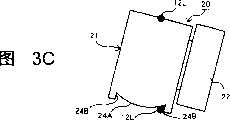
图3A~图3C是表示图1所示图像显示装置中的显示装置的摆动方式的侧视图。3A to 3C are side views showing how the display device in the image display device shown in FIG. 1 swings.
图4是表示从上方看到的图1所示图像显示装置的显示装置的透视图。FIG. 4 is a perspective view showing a display device of the image display device shown in FIG. 1 seen from above.
图5是图1所示遮蔽板的剖视图。FIG. 5 is a cross-sectional view of the shielding plate shown in FIG. 1 .
在图6中,分图(L)是示意地表示在使用图1所示图像显示装置时在使用者的左眼中可以看到的物体的图,分图(R)是示意地表示在使用图1所示图像显示装置时在使用者的右眼中可以看到的物体的图。In FIG. 6, a sub-graph (L) is a diagram schematically showing objects that can be seen in the user's left eye when using the image display device shown in FIG. The image display device shown in 1 is a diagram of objects that can be seen in the user's right eye.
图7是示意地表示在使用图1所示图像显示装置时、使用者基于图6所示物体可以认识的物体。FIG. 7 schematically shows objects that a user can recognize based on the objects shown in FIG. 6 when using the image display device shown in FIG. 1 .
图8是表示从前面看到的第二实施形态的图像显示装置的立体图。Fig. 8 is a perspective view showing an image display device according to a second embodiment seen from the front.
图9是表示从上后方看到的第三实施形态的图像显示装置的整体的立体图。Fig. 9 is a perspective view showing the whole of the image display device according to the third embodiment seen from above and behind.
图10是表示从上后方看到的第四实施形态的图像显示装置的整体的立体图。Fig. 10 is a perspective view showing the whole of an image display device according to a fourth embodiment seen from above and behind.
图11是表示与第四实施形态的图像显示装置的右眼用框架相连的腿部的结构的图。Fig. 11 is a diagram showing the configuration of legs connected to the right-eye frame of the image display device according to the fourth embodiment.
图12A及图12B是表示第四实施形态的图像显示装置的腿部的弯曲状态的侧视图。12A and 12B are side views showing the bent state of the legs of the image display device according to the fourth embodiment.
图13是表示第五实施形态的图像显示装置的使用状态的主视图。Fig. 13 is a front view showing a state of use of the image display device according to the fifth embodiment.
图14是表示第五实施形态的图像显示装置的使用状态的侧视图。Fig. 14 is a side view showing the state of use of the image display device according to the fifth embodiment.
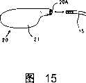
图15是表示第五实施形态的图像显示装置的显示装置相对于本体的安装方法的图。Fig. 15 is a diagram showing a method of attaching the display device to the main body of the image display device according to the fifth embodiment.
图16A是表示第六实施形态的图像显示装置的固定用板的结构的主视图,图16B是表示同一固定用板的结构的侧剖视图。16A is a front view showing the structure of a fixing plate of an image display device according to a sixth embodiment, and FIG. 16B is a side sectional view showing the structure of the same fixing plate.
图17是从背面方向看到的第六实施形态的图像显示装置的显示装置的立体图。Fig. 17 is a perspective view of the display device of the image display device according to the sixth embodiment seen from the rear direction.
图18A是表示第六实施形态的图像显示装置的固定用板的变形例的结构的主视图,图18B是表示同一固定用板的变形例的结构的侧剖视图。18A is a front view showing the structure of a modified example of the fixing plate of the image display device according to the sixth embodiment, and FIG. 18B is a side sectional view showing the structure of a modified example of the same fixing plate.
图19是从背面方向看到的第六实施形态的图像显示装置的变形例的显示装置的立体图。Fig. 19 is a perspective view of a display device according to a modified example of the image display device according to the sixth embodiment seen from the back side.
具体实施方式Detailed ways
下面,参照附图对本发明的较佳的第一~第六实施形态进行详细说明。Next, preferred first to sixth embodiments of the present invention will be described in detail with reference to the drawings.
另外,在各实施形态的说明中,相同的部件使用相同的符号标记,根据情况而省略重复说明。In addition, in the description of each embodiment, the same components are denoted by the same reference numerals, and overlapping descriptions are omitted in some cases.
(第一实施形态)(first embodiment)
图1是表示从上后方看到的本发明的第一实施形态的图像显示装置1的整体的立体图。另外,在实施形态的说明中,图像显示装置1的后方是指在图像显示装置1安装在使用者的脸上时靠近使用者的脸的一侧。FIG. 1 is a perspective view showing the whole of an
该图像显示装置1构成为,包括:本体10、用于显示图像的显示装置20、以及遮蔽板30。如下所述,显示装置20和遮蔽板30构成为相对于本体10可自由拆装。The
本体10用于保持显示装置20和遮蔽板30,且用于将图像显示装置1固定到使用者头部上。图像显示装置1在使用时,本体10安装在使用者的头部。图像显示装置1通过将本体10的腿部11搭在使用者的两耳上而固定地安装在使用者的头部。另外,在不使用图像显示装置1时,腿部11朝框架12折叠。The
本实施形态中的本体10形成为眼镜的镜架形状,构成为,包括:左右两条腿部11、以及框架12。但是,本体10不必非得形成为眼镜的镜架形状。框架12包括:右眼用框架12R、以及左眼用框架12L。右眼用框架12R和左眼用框架12L用鼻梁架12B连结。在该鼻梁架12B上设有托叶。右眼用框架12R是图像显示装置1固定地安装在使用者的头部时位于使用者的右眼前方的框架12,左眼用框架12L是图像显示装置1固定地安装在使用者的头部时位于使用者的左眼前方的框架12。虽然不必非得这样,但在本实施形态中,两个框架12L、12R都形成为环状。更详细地,两个框架12L、12R均利用金属制的棒状体制成,是用半圆状的弧使两根平行直线的两端相互之间连接而形成的横向较长的椭圆形状。The
另外,在本实施形态的右眼用框架12R和左眼用框架12L的内侧并未嵌入有透镜。In addition, lenses are not fitted inside the right-
在本实施形态的图像显示装置1中,在右眼用框架12R和左眼用框架12L中的一方上安装有显示装置20,另一方上安装有遮蔽板30。在图1中,在左眼用框架12L的内侧和右眼用框架12R的内侧分别固定有显示装置20和遮蔽板30。显示装置20和遮蔽板30的位置关系也可以相反。最好使显示装置20位于使用者容易看见图像的一只眼睛的前面并固定。In the
显示装置20相当于本发明的显示构件。图像显示装置1在使用时,显示装置20位于使用者的一只眼睛(在本实施形态中是左眼)的前面,通过将规定图像的图像光引入左眼,使得使用者可用左眼看见图像。所述图像以存在于作为该左眼的视野的一部分的显示范围内的状态,使得使用者看见。The
如图2所示,显示装置20包括形成为大致长方体形状的盒子21。虽然并不局限于此,但本实施形态的盒子21为树脂制。在盒子21的后侧的面上设有镜筒22。镜筒22为大致圆筒形状。在盒子21的顶面上设有截面大致为U字型的凹槽23。在盒子21的底面上设有用于使显示装置20在上下方向上摆动的曲面部24。曲面部24形成为如图3A~图3C所示的截面形状。曲面部24包括鞍状的凸面24A。在凸面24A的两端部分(在鞍的倾斜方向上的两端部分)上分别设有从凸面24A的两端部分突出的台阶部24B。As shown in FIG. 2 , the
凹槽23与左眼用框架12L的上下两根平行部分中的上侧部分相嵌合。曲面部24与左眼用框架12L的上下两根平行部分中的下侧部分相抵接。通过将左眼用框架12L的上下两根平行部分中的上侧部分嵌入凹槽23内部,将左眼用框架12L的上下两根平行部分中的下侧部分抵接在曲面部24上,而将显示装置20安装在左眼用框架12L的内侧。The groove 23 fits in the upper part of the upper and lower parallel parts of the left-
如图3A~图3C所示,可以使安装在左眼用框架12L上的显示装置20在上下方向上摆动。该摆动是通过使曲面部24的鞍状凸面24A一边抵接在左眼用框架12L的上下两根平行部分中的下侧部分上一边滑动(图3B)来进行的。显示装置20可以摆动到左眼用框架12L的上下两根平行部分中的下侧部分抵接在台阶部24B上之前的任何位置(图3A、图3C)。另外,显示装置20可以固定在图3A和图3C所示两个位置之间的任意位置上。As shown in FIGS. 3A to 3C , the
通过使处于与左眼用框架12L的上下两根平行部分中的上侧部分相嵌合的状态的凹槽23沿着左眼用框架12L的上下两根平行部分中的上侧部分滑动,并使与左眼用框架12L的上下两根平行部分中的下侧部分相抵接的凸面24A沿着左眼用框架12L的上下两根平行部分中的下侧部分滑动,可以使安装在左眼用框架12L上的显示装置20在与左眼用框架12L的上下两根平行部分的长度方向相同的方向上平行移动。By sliding the groove 23 in a state of being fitted with the upper part of the upper and lower parallel parts of the left-
这样,使用者可以调整显示装置20的左右方向的位置和上下方向的角度,使得可以利用显示装置20看见的图像处于更容易看见的位置上。In this way, the user can adjust the position in the left-right direction and the angle in the up-down direction of the
显示装置20与电缆C相连。如下所述,该电缆C将图像信号传给显示装置20。例如,利用环状构件(该构件省略了图示。)将电缆C铆接固定在左侧的腿部11上。另外,电缆C连接在显示装置20的外侧面(图像显示装置1安装在使用者脸上时的脸的侧面侧的面)上。The
另外,如图4所示,在盒子21的内部设有转换基板25、背光灯构件26和液晶显示器27。In addition, as shown in FIG. 4 , a conversion substrate 25 , a backlight member 26 , and a liquid crystal display 27 are provided inside the
在镜筒22的内部设有放大透镜28。A magnifying lens 28 is provided inside the
转换基板25与电缆C相连,将通过电缆C从外部传来的图像信号转换成可以在液晶显示器27中显示的图像,对液晶显示器27进行控制。The conversion substrate 25 is connected to the cable C, and converts the image signal transmitted from the outside through the cable C into an image that can be displayed on the liquid crystal display 27 to control the liquid crystal display 27 .
背光灯构件26包括从背后照射液晶显示器27的背光灯,对背光灯进行控制。The backlight unit 26 includes a backlight that illuminates the liquid crystal display 27 from behind, and controls the backlight.
液晶显示器27在转换基板25的控制下显示作为动画或静止画面的规定图像。The liquid crystal display 27 displays a predetermined image as a moving image or a still image under the control of the switch board 25 .
放大透镜28对液晶显示器27中显示的图像的图像光进行放大。另外,放大透镜28并非一定是一片,有时也可以由多片透镜构成。另外,本实施形态的放大透镜28通过旋转镜筒22而前后动作。由此,即使使用者的视力有一定的差异,也可以使所述图像很好地在使用者的眼睛中成像。用于使放大透镜28前后动作的结构形式不限,例如,可以通过使镜筒22构成为两层,在这些内侧件的外表面和外侧件的内表面上切螺纹进行螺合,并将放大透镜28固定在镜筒22的内侧件的内表面上来实现。The magnifying lens 28 magnifies image light of an image displayed on the liquid crystal display 27 . In addition, the magnifying lens 28 does not have to be a single piece, and may consist of a plurality of lenses in some cases. In addition, the magnifying lens 28 of this embodiment moves back and forth by rotating the
另外,转换基板25对液晶显示器27中显示的图像进行控制。转换基板25通过电缆C从显示装置20的外部接收视频信号或RGB信号等图像信号,并将基于该图像信号的图像显示在显示器27中。但是,转换基板25也可不设在显示装置20的内部,而将其全部或一部分设在显示装置20外。另外,也可以无线接收图像信号。In addition, the conversion substrate 25 controls the image displayed on the liquid crystal display 27 . The conversion substrate 25 receives an image signal such as a video signal or an RGB signal from outside the
另外,转换基板25也可以构成为包括电视调谐器。这种情况下,转换基板25通过接收一般的电视播放用的电波并对其解码,从而将电视节目的图像显示在液晶显示器27中。转换基板25在液晶显示器27中显示的图像不局限于此,可以涉及基于记录在DVD等记录媒体中的图像数据进行再生的图像、基于由个人计算机、游戏装置等的计算机生成的图像数据进行再生的图像等多方面。In addition, the conversion substrate 25 may also be configured to include a TV tuner. In this case, the conversion board 25 receives and decodes radio waves for general TV broadcasting, thereby displaying the image of the TV program on the liquid crystal display 27 . The image displayed on the liquid crystal display 27 by the conversion substrate 25 is not limited thereto, and may be an image reproduced based on image data recorded in a recording medium such as a DVD, or an image reproduced based on image data generated by a computer such as a personal computer or a game device. images and many other aspects.
遮蔽板30相当于本发明的遮蔽构件。The shielding
遮蔽板30在图像显示装置1使用时位于使用者的另一只眼睛(在本实施形态中是右眼)的前面,使进入使用者右眼视野的遮蔽范围内的光弱于进入使用者左眼的显示范围内的光。另外,所谓遮蔽范围是指与显示范围大致对应的范围、或包含该范围的更大范围。这在下面叙述。The shielding
在本实施形态中,遮蔽板30为矩形的板状体。另外,如图5所示,在其上下具有槽31。遮蔽板30可以由树脂、木材、纸、金属等形成,但在本实施形态中,由树脂形成。该遮蔽板30可以由不透明的树脂制成,但只要透光性足够低,也可以由半透明的树脂制成。例如,遮蔽板30可以使用颜色较深、与透光率小于等于50%的透镜(例如,太阳镜的无度数透镜)相同的材料。In this embodiment, the shielding
遮蔽板30可以在与右眼用框架12R的上下两根平行部分的长度方向相同的方向上平行移动。The shielding
对本实施形态的图像显示装置1的使用方法进行说明。A method of using the
在实际使用图像显示装置1之前,进行准备。Preparations are made before the
作为使用图像显示装置1的准备,进行如下操作。As a preparation for using the
作为使用图像显示装置1的准备,进行显示装置20的调整。这是在本体10上未安装有显示装置20时,在将显示装置20安装到本体10上后,通过调整显示装置20的左右方向的位置和上下方向的角度来进行的。另外,作为上述准备,进行遮蔽板30的位置调整。遮蔽板30的位置调整通过使其在左右方向上平行移动来进行。另外,作为上述准备,进行放大透镜28的调整。根据使用者的视力,使放大透镜28在前后方向上移动。另外,如上所述,在本实施形态中,通过旋转镜筒22使放大透镜28进行前后动作(沿光轴方向移动),但放大透镜28在光轴方向上的移动也可以利用其它方法进行。另外,也可以根据使用者的视力使放大透镜28例如可以连同镜筒22一起更换。As a preparation for using the
然后,将图像显示装置1安装到使用者的脸上并进行固定。该固定通过将图像显示装置1的腿部11卡在双耳上进行。Then, the
在这种状态下接通与电缆C相连的物体(例如,DVD播放机等)的电源,进行必要的操作后,图像信号便会通过电缆C送来。该图像信号通过转换基板25送入液晶显示器27。液晶显示器27基于该图像信号进行图像的显示。来自背光灯构件26所具有的背光灯的光、即该图像的图像光通过放大透镜28送入使用者的左眼,在使用者的左眼中成像。In this state, the object connected to the cable C (for example, a DVD player, etc.) is powered on, and the image signal is sent through the cable C after necessary operations are performed. The image signal is sent to the liquid crystal display 27 through the conversion substrate 25 . The liquid crystal display 27 displays an image based on the image signal. The light from the backlight included in the backlight unit 26 , that is, the image light of the image is sent to the user's left eye through the magnifying lens 28 , and forms an image in the user's left eye.
此时,在使用者的左眼中,可以如图6(L)所示地看到图像GL。如图6(L)所示,一般在昏暗的空间SL中,可以看到图像GL漂浮着。可以看到图像GL存在的范围相当于本发明的显示范围。另外,图像GL周围的空间SL对应于放大透镜28的光瞳。另外,在空间SL的周围可以模糊地看到镜筒22的前端。之所以只能模糊地看到镜筒22的前端,是因为其比使用者的左眼的近点更靠近使用者。另外,在镜筒22的周围可以看到外界OL。外界OL的周边与使用者的左眼的视野一致。本实施形态的显示范围的大小远小于使用者的左眼的视野的1/3。另外,该显示范围的视场角在左右方向上为20°左右。At this time, the user's left eye can see the image GL as shown in FIG. 6(L). As shown in FIG. 6(L), generally in a dark space SL, the image GL can be seen floating. The range in which the image GL can be seen corresponds to the display range of the present invention. In addition, the space SL around the image GL corresponds to the pupil of the magnifying lens 28 . In addition, the front end of the
在本实施形态中,使用者在看着显示范围的状态下不用移动视线便可以识别外界的景色。如果使用者移动视线,则可以用双眼看到更多的外界景色。In this embodiment, the user can recognize the scenery of the outside world without moving his/her eyes while looking at the display area. If the user moves his eyes, he can see more external scenery with both eyes.
另一方面,此时在使用者的右眼的前面存在着遮蔽板30。此时,如图6(R)所示,在使用者的右眼中可以模糊地看到遮蔽板30。之所以只能模糊地看到遮蔽板30,是因为该遮蔽板30的位置比使用者的右眼的近点更靠近使用者的右眼。在使用者的右眼中,主要可以看到外界OR。所述遮蔽板30以包含与左眼的显示范围GL对应的范围GL’的状态,可以在右眼的视野中昏暗地看到。这意味着从具有遮蔽板30的范围(相当于本发明的遮蔽范围)进入右眼的光弱于从可以看到图像GL的范围进入左眼的光。另外,GL’是为了说明才图示的,在实际中看不到。本来,整个包含GL’在内的部分作为遮蔽板30可以昏暗地看到。On the other hand, at this time, the shielding
在本实施形态中,使用者在看着遮蔽板30的状态下不用移动视线便可以识别外界的景色。若移动视线,则当然可以在更大的范围内看到外界的景色。In this embodiment, the user can recognize the scenery of the outside world without moving the line of sight while looking at the shielding
此时,左眼看到的图像GL和右眼看到的遮蔽板30在大脑中合成,可以如图7所示地看到。At this time, the image GL seen by the left eye and the shielding
即,可以看到图像GL好像位于昏暗的遮蔽板30上。在本实施形态中,如果对左眼视野中的图像GL的显示范围和右眼视野中的与其对应的范围进行比较,那么左眼受到的来自显示范围的光刺激远大于右眼受到的来自与其对应的范围的光刺激,故视野斗争几乎不会发生。That is, the image GL can be seen as if located on the
在这种状态下,使用者可以欣赏图像。In this state, the user can enjoy images.
另外,为了可以看到图像GL好像位于遮蔽板30上,使用者可以一边看图像GL,一边进行显示装置20的位置及角度调整、以及遮蔽板30的位置调整。In addition, the user can adjust the position and angle of the
(第二实施形态)(Second Embodiment)
第二实施形态的图像显示装置2表示在图8中。An
本实施形态的图像显示装置2基本上与第一实施形态的图像显示装置1相同。The
不同的是本体10的结构。The difference is the structure of the
本实施形态的本体10与第一实施形态时一样,构成为包括腿部11、以及框架12,但第一实施形态的框架12形成为将均形成为环状的左眼用框架12L及右眼用框架12R用鼻梁架12B连接的形状,与其不同,第二实施形态的框架12形成为一个环状。The
因此,本实施形态的本体10并不构成为眼镜的镜架形状。Therefore, the
另外,在第二实施形态的图像显示装置2的本体10的中心部分下方设有与安装在眼镜上的托叶一样的托叶。In addition, under the central part of the
第二实施形态的图像显示装置2的显示装置20及遮蔽板30的结构与第一实施形态的显示装置20及遮蔽板30的结构相同,安装到该框架12上的方法也与第一实施形态的显示装置20及遮蔽板30安装到本体10上的方法相同。但是,在本实施形态中,显示构件20位于右眼的前面,遮蔽板30位于左眼的前面。The structures of the
显示装置20可以调整左右方向的位置和上下方向的角度,遮蔽板30可以调整左右方向的位置。The
第二实施形态的图像显示装置2的使用方法与第一实施形态的图像显示装置1的使用方法相同。The method of using the
(第三实施形态)(third embodiment)
第三实施形态的图像显示装置3表示在图9中。An
第三实施形态的图像显示装置3基本上与第一实施形态的图像显示装置1相同。The
不同的是,在第一实施形态的图像显示装置1的本体10上安装有显示装置20和遮蔽板30,但在第三实施形态的图像显示装置3的本体上安装有两个显示装置20。第三实施形态的图像显示装置3的本体10与第一实施形态的图像显示装置1的本体10相同。The difference is that a
在两个显示装置20中,位于左眼前面的显示装置20与第一实施形态的图像显示装置1的相同。另一方面,位于右眼前面的显示装置20构成为与位于左眼前面的显示装置20左右对称。与位于右眼前面的显示装置20相连的电缆C用与位于左眼前面的显示装置20同样的方法固定在右侧的腿部11上。Of the two
第三实施形态的显示装置20均可调整左右方向的位置和上下方向的角度。The
对第三实施形态的图像显示装置3的使用方法进行说明。A method of using the
第三实施形态的图像显示装置3的使用方法基本上与第一实施形态的图像显示装置1的使用方法相同。The method of using the
不同的是,在第一实施形态的图像显示装置1的使用准备中进行一个显示装置20的调整、遮蔽板30的位置调整、以及放大透镜28的调整,但在第三实施形态的图像显示装置3的使用准备中,代替它的是,进行两个显示装置20的调整、以及放大透镜28的调整。两个显示装置20的调整是在本体10上未安装有显示装置20时,在将两个显示装置20安装到本体10上后,通过调整两个显示装置20的左右方向的位置和上下方向的角度来进行的。The difference is that the adjustment of one
在上述准备完成后,将图像显示装置3安装到使用者的脸上并进行固定。该固定通过将图像显示装置3的腿部11卡在双耳上进行。After the above preparations are completed, the
在这种状态下接通与电缆C相连的物体(例如,DVD播放机等)的电源,进行必要的操作后,图像信号便会通过电缆C送来。该图像信号通过转换基板25送入液晶显示器27。液晶显示器27基于该图像信号进行图像的显示。来自背光灯构件26所具有的背光灯的光、即该图像的图像光通过放大透镜28送入使用者的右眼或左眼,在使用者的右眼或左眼中成像。In this state, the object connected to the cable C (for example, a DVD player, etc.) is powered on, and the image signal is sent through the cable C after necessary operations are performed. The image signal is sent to the liquid crystal display 27 through the conversion substrate 25 . The liquid crystal display 27 displays an image based on the image signal. The light from the backlight of the backlight unit 26 , that is, the image light of the image is sent to the user's right or left eye through the magnifying lens 28 , and formed in the user's right or left eye.
此时,在左眼中,如图6(L)所示地可以看到图像GL。在右眼中也可以看到相同的图像。At this time, the left eye can see the image GL as shown in FIG. 6(L). The same image is also seen in the right eye.
此时,左眼看到的图像GL和右眼看到的同样的图像在大脑中合成,如图6(L)所示地可以看到。At this time, the image GL seen by the left eye and the same image seen by the right eye are synthesized in the brain as shown in FIG. 6(L).
这样,使用者便可以看到图像。另外,使用者在看着显示范围的状态下不用移动视线便可以识别外界的景色,若移动视线,则可以看到更多的外界景色。In this way, the user can see the image. In addition, the user can recognize the external scenery without moving the line of sight while looking at the display area, and can see more external scenery by moving the line of sight.
(第四实施形态)(Fourth Embodiment)
第四实施形态的图像显示装置4的概略结构如图10所示。A schematic configuration of an image display device 4 according to the fourth embodiment is shown in FIG. 10 .
本实施形态的图像显示装置4基本上与第一实施形态的图像显示装置1相同。The image display device 4 of this embodiment is basically the same as the
不同的是本体10的结构,在其它方面没有大的改变。The difference is the structure of the
本实施形态的本体10与第一实施形态时相同,构成为包括腿部11、以及框架12,但第四实施形态的图像显示装置4的腿部11的结构构成为与第一实施形态的图像显示装置1的腿部11不同的结构。The
第四实施形态的图像显示装置4的腿部11均构成为基端部分(框架12侧的部分)与前端部分(远离框架12的部分)所成的角度可变。通过改变腿部11的基端部分与前端部分所成的角度,第四实施形态的图像显示装置4可以进行在上下方向上的角度调整。The
用图11对第四实施形态的腿部11的结构进行详述。另外,两条腿部11的结构为左右对称,其余没有不同,故用图11只对右侧的腿部11的结构进行说明。The structure of the
图11是表示与右眼用框架12R相连的腿部11的结构的图。FIG. 11 is a diagram showing the configuration of the
腿部11分割成两部分。腿部11构成为包括:与右侧用框架12R相连的基端侧构件111、以及与其相连的前端侧构件112。The
基端侧构件111构成为包括:两个夹持构件111A,从上下夹持设在右眼用框架12R上的开设有孔P的板构件121R,并分别开设有孔Q;以及基端侧连接构件111B,从两个夹持构件111A处起大致弯折90度地设置,并开设有孔R。The base
前端侧构件112构成为包括:与基端侧连接构件111B相连且开设有孔S的前端侧连接构件112A、以及前端侧构件本体112B。前端侧构件本体112B为卡在使用者的耳朵上的部分。The distal-
如图11中的虚线所示,板构件121R和夹持构件111通过使螺栓113贯穿孔P、Q来进行连接。另一方面,如图11中的虚线所示,基端侧连接构件111B和前端侧连接构件112A通过使螺栓114贯穿孔R、S来进行连接。As shown by the dashed line in FIG. 11 , the
由此,腿部11能够以螺栓113为轴在水平面内转动,可以相对于框架12闭合。另外,腿部11能够以螺栓114为轴在垂直平面内弯折。由此,使腿部11的基端部分(框架12侧的部分)与前端部分(远离框架12侧的部分)所成的角度可变。Thereby, the
如图10所示,在本实施形态的图像显示装置4的本体10上设有显示装置20和遮蔽板30。另外,如图12A、图12B所示,如果从侧面方向看使用时的图像显示装置4,那么显示装置20的镜筒22的前端位于连接螺栓114的直线上。As shown in FIG. 10, a
由此,即使改变腿部11的基端侧构件111与前端侧构件112的角度,如图12A、图12B所示,镜筒22的前端位置也不会改变。Accordingly, even if the angle between the
另外,本第四实施形态的图像显示装置4的使用方法基本上与第一实施形态的图像显示装置1的使用方法相同。In addition, the method of using the image display device 4 of the fourth embodiment is basically the same as the method of using the
不同的只是显示装置20的角度调整方法。在使用图像显示装置4之前或使用过程中,使用者通过用手指捏着使框架12在上下方向上移动等,对显示装置20的角度进行调整。The difference is only the angle adjustment method of the
另外,通过在第四实施形态的本体10上安装显示装置20以代替遮蔽板30,也可以在本体10上安装两个显示装置20。这种情况下,如果从侧面方向看使用时的图像显示装置4,那么两个显示装置20的镜筒22的前端均位于连接螺栓114的直线上。In addition, by attaching the
(第五实施形态)(fifth embodiment)
第五实施形态的图像显示装置5的使用状态表示在图13、图14中。The state of use of the
本实施形态的图像显示装置5基本上与第一实施形态的图像显示装置1相同。The
第五实施形态的图像显示装置5与第一实施形态的图像显示装置1在本体10的结构方面不同。The
如图13、图14所示,本实施形态的本体10形成为如同耳机的形状。更具体地,该本体10形成为如同后挂式(日文:バツクア一ムスタイル)的耳机的形状。As shown in FIG. 13 and FIG. 14, the
本体10包括:弯曲的臂部13、以及设在臂部13两端上的耳罩14。在两耳罩14的边缘部分具有未图示的耳部(日文:イヤ一パツト),在耳罩14的内部具有未图示的扬声器。本体10通过如此构成而起到作为耳机的作用。The
另外,本体10从将图像信号传入下述显示装置20的装置等接收声音信号,基于该声音信号用扬声器对声音进行再生,传入使用者的耳朵。Also, the
从两个耳罩14起延伸有辅助臂15。该辅助臂15的前端使该图像显示装置5位于使用中的使用者的眼睛的前边。辅助臂15用于在其前端上安装显示装置20。Extending from the two
另外,第五实施形态的图像显示装置5的显示装置20与第一实施形态的显示装置20在盒子21的形状上有所不同,在其它方面同样地构成。In addition, the
该图像显示装置5的显示装置20均与第一实施形态的图像显示装置1的显示装置20一样,可以调整左右方向的位置和上下方向的角度。Like the
该结构如下所述。The structure is described below.
如图15所示,在辅助臂15的前端上切有螺纹。As shown in FIG. 15 , threads are cut on the front end of the
另外,如图15所示,在显示装置20的外侧部分上设有孔20A,且在该孔20A的内周面上切有螺纹。即,通过使作为阳螺纹的辅助臂15的前端插入作为阴螺纹的孔20A中进行螺合,可以在辅助臂15的前端上固定显示装置20。In addition, as shown in FIG. 15 , a
此时,通过使显示装置20相对于辅助臂15进行一定的旋转,便可以调整显示装置20的左右方向的位置和上下方向的角度。另外,如果进行该旋转,那么与显示装置20相连的电缆C也可能会因扭转而断裂。为了避免这种情况,在显示装置20如此构成时,最好使显示装置20和电缆C可自由拆装,在进行上述旋转时,则将电缆C从显示装置20上分离。或者,也可以不用电缆C,使显示装置20无线地接收图像信号。另外,可以不用电缆C而使显示装置20无线地接收图像信号,这在第一~第四实施形态及下述第六实施形态的情况下也一样。At this time, the position of the
(第六实施形态)(sixth embodiment)
本实施形态的图像显示装置基本上与第一实施形态的图像显示装置1相同。The image display device of this embodiment is basically the same as the
除了用于将显示装置20固定到本体上的结构之外,没有大的改变。但是,在本实施形态中,显示装置20位于右眼的前面,遮蔽板位于左眼的前面。Except for the structure for fixing the
参照图16A、图16B及图17对第六实施形态的图像显示装置的显示装置20安装到本体上的方法进行说明。图16A是表示第六实施形态的图像显示装置的固定用板50的结构的主视图,图16B是表示该固定用板50的结构的侧剖视图,图17是从背面方向看到的第六实施形态的图像显示装置的显示装置20的立体图。A method of attaching the
本实施形态的显示装置20安装在右眼用框架12R的内侧部分中。另外,包括本实施形态的右眼用框架12R在内的本体的结构与第一实施形态的本体的结构相同。The
在本体的右眼用框架12R上装备有与遮蔽板一样在上下具有槽51的固定用板50。在该固定用板50的正面上设有凸曲面52。该凸曲面52向使用中的图像显示装置的正面方向凸设。凸曲面52构成为规定的球面的一部分。The right-
另一方面,如图17所示,在显示装置20的背面侧的面上设有凹曲面29。该凹曲面29形成为与所述凸曲面52对应的形状。On the other hand, as shown in FIG. 17 , a concave
凸曲面52和凹曲面29利用磁力相互吸附在一起。例如,通过使设有凸曲面52和凹曲面29的构件都由磁体形成,或一方的构件为磁体、另一方的构件由可吸附到磁体上的金属形成等,使凸曲面52和凹曲面29利用磁力相互吸附在一起。The convex
在此,如果使凹曲面29吸附到凸曲面52上,那么显示装置20便可以安装到本体上。这种状态下,通过使凹曲面29相对于凸曲面52滑动,可以改变显示装置20相对于固定用板50的角度。例如,显示装置20可以相对于本体在上下方向上摆动。Here, if the concave
另外,通过使安装有显示装置20的固定用板50沿左右方向移动,可以调整显示装置20的左右方向的位置。In addition, the position of the
这样,该图像显示装置也可以调整显示装置20的左右方向的位置和上下方向的角度。In this way, the image display device can also adjust the position of the
另外,也可与上述情况相反,在显示装置20上设置凸曲面52,在固定用板50上设置凹曲面29。这样也可以调整显示装置20的左右方向的位置和上下方向的角度。这种情况下的固定用板50的主视图表示在图18A中,侧剖视图表示在图18B中,显示装置20的后视图表示在图19中。In addition, contrary to the above, the convex
Claims (12)
Translated fromChineseApplications Claiming Priority (2)
| Application Number | Priority Date | Filing Date | Title |
|---|---|---|---|
| JP043558/2004 | 2004-02-19 | ||
| JP2004043558 | 2004-02-19 |
Publications (2)
| Publication Number | Publication Date |
|---|---|
| CN1934485Atrue CN1934485A (en) | 2007-03-21 |
| CN100414344C CN100414344C (en) | 2008-08-27 |
Family
ID=34879312
Family Applications (1)
| Application Number | Title | Priority Date | Filing Date |
|---|---|---|---|
| CNB2005800090613AExpired - Fee RelatedCN100414344C (en) | 2004-02-19 | 2005-02-21 | image display device |
Country Status (6)
| Country | Link |
|---|---|
| US (1) | US20070279318A1 (en) |
| EP (1) | EP1720058A4 (en) |
| JP (1) | JP4601609B2 (en) |
| KR (1) | KR20060134106A (en) |
| CN (1) | CN100414344C (en) |
| WO (1) | WO2005081037A1 (en) |
Cited By (7)
| Publication number | Priority date | Publication date | Assignee | Title |
|---|---|---|---|---|
| CN101846800A (en)* | 2009-03-25 | 2010-09-29 | 奥林巴斯株式会社 | Glasses-mounted type image display device |
| CN101846801A (en)* | 2009-03-25 | 2010-09-29 | 奥林巴斯株式会社 | Eyeglass-mounted type image display device |
| CN101846804A (en)* | 2009-03-25 | 2010-09-29 | 奥林巴斯株式会社 | Glasses-mounted type image display device |
| CN102628991A (en)* | 2011-02-04 | 2012-08-08 | 精工爱普生株式会社 | Head-mounted display device and control method for the head-mounted display device |
| CN104662466A (en)* | 2012-09-26 | 2015-05-27 | 索尼公司 | Head-mounted display |
| CN107111136A (en)* | 2014-12-31 | 2017-08-29 | 埃西勒国际通用光学公司 | Binocular device including a monocular display device |
| CN108931852A (en)* | 2017-05-22 | 2018-12-04 | 宏达国际电子股份有限公司 | Head-mounted display system, method for adjusting hidden area mask and program product |
Families Citing this family (9)
| Publication number | Priority date | Publication date | Assignee | Title |
|---|---|---|---|---|
| EP1847724A4 (en)* | 2005-01-28 | 2010-09-01 | Scalar Corp | Universal joint and image display unit |
| CN200997663Y (en)* | 2007-01-18 | 2007-12-26 | 谭健民 | Small high-resolution stereo video-frequency display device |
| JP5131254B2 (en)* | 2009-07-15 | 2013-01-30 | ブラザー工業株式会社 | Attachment device for HMD |
| EP2932330A1 (en)* | 2012-12-13 | 2015-10-21 | Kopin Corporation | Spectacle with invisible optics |
| US10182606B2 (en)* | 2015-02-05 | 2019-01-22 | Amit TAL | Helmut with monocular optical display |
| EP3104215A1 (en)* | 2015-06-09 | 2016-12-14 | Nokia Technologies Oy | Apparatus and method for near eye display |
| KR102812420B1 (en)* | 2019-08-28 | 2025-05-23 | 엘지전자 주식회사 | Electronic device |
| US11774770B2 (en)* | 2020-06-03 | 2023-10-03 | Universal City Studios Llc | Interface device with three-dimensional (3-D) viewing functionality |
| JP2023076458A (en)* | 2022-04-05 | 2023-06-01 | 株式会社東芝 | Electronic apparatus and display method |
Family Cites Families (15)
| Publication number | Priority date | Publication date | Assignee | Title |
|---|---|---|---|---|
| US2172959A (en)* | 1939-02-11 | 1939-09-12 | Ben Hur Products Inc | Sunglasses |
| IT7911669V0 (en)* | 1979-05-25 | 1979-05-25 | Fortini Umberto | CLUTCH FOR THE ARTICULATION OF GLASSES TEMPLES |
| JPS60143996U (en)* | 1984-03-05 | 1985-09-24 | 日本パツク株式会社 | Holding stand for ornaments, etc. |
| JPH07209600A (en)* | 1994-01-19 | 1995-08-11 | Seiko Epson Corp | Information display device |
| JPH0816655A (en)* | 1994-02-18 | 1996-01-19 | Hitachi Ltd | Surface acoustic wave device and its analysis method and analysis system |
| JPH08166557A (en)* | 1994-06-23 | 1996-06-25 | Seiko Epson Corp | Head-mounted display device |
| DE69531593T2 (en)* | 1994-06-23 | 2004-06-24 | Seiko Epson Corp. | INDICATOR ON THE HEAD |
| JPH0836155A (en)* | 1994-07-25 | 1996-02-06 | Olympus Optical Co Ltd | Head-mounted video display device |
| US6034653A (en)* | 1997-08-01 | 2000-03-07 | Colorado Microdisplay, Inc. | Head-set display device |
| JP2000111828A (en)* | 1998-10-06 | 2000-04-21 | Sharp Corp | Wearable image display device |
| JP2001305474A (en)* | 2000-04-24 | 2001-10-31 | Olympus Optical Co Ltd | Head-mounted video display device |
| JP2003121778A (en)* | 2001-10-12 | 2003-04-23 | Shimadzu Corp | Head mounted display with camera |
| US6728974B2 (en)* | 2001-10-12 | 2004-05-04 | Jake Wadsworth | Safety goggles with earplugs |
| WO2003048838A1 (en)* | 2001-12-05 | 2003-06-12 | Kopin Corporation | Head-mounted display system |
| ITTV20020085A1 (en)* | 2002-07-22 | 2004-01-22 | Foval Srl | SIMPLIFIED HINGE DEVICE AND AUCTION SO OBTAINED, ESPECIALLY FOR GLASSES FRAMES |
- 2005
- 2005-02-21USUS10/589,813patent/US20070279318A1/ennot_activeAbandoned
- 2005-02-21JPJP2006510332Apatent/JP4601609B2/ennot_activeExpired - Fee Related
- 2005-02-21CNCNB2005800090613Apatent/CN100414344C/ennot_activeExpired - Fee Related
- 2005-02-21WOPCT/JP2005/003224patent/WO2005081037A1/enactiveApplication Filing
- 2005-02-21EPEP05710755Apatent/EP1720058A4/ennot_activeWithdrawn
- 2005-02-21KRKR1020067019119Apatent/KR20060134106A/ennot_activeAbandoned
Cited By (13)
| Publication number | Priority date | Publication date | Assignee | Title |
|---|---|---|---|---|
| CN101846804B (en)* | 2009-03-25 | 2014-02-26 | 奥林巴斯株式会社 | Glasses-mounted image display device |
| CN101846801A (en)* | 2009-03-25 | 2010-09-29 | 奥林巴斯株式会社 | Eyeglass-mounted type image display device |
| CN101846804A (en)* | 2009-03-25 | 2010-09-29 | 奥林巴斯株式会社 | Glasses-mounted type image display device |
| CN101846800A (en)* | 2009-03-25 | 2010-09-29 | 奥林巴斯株式会社 | Glasses-mounted type image display device |
| CN102628991B (en)* | 2011-02-04 | 2015-07-08 | 精工爱普生株式会社 | Head-mounted display device and control method for the head-mounted display device |
| CN102628991A (en)* | 2011-02-04 | 2012-08-08 | 精工爱普生株式会社 | Head-mounted display device and control method for the head-mounted display device |
| CN104662466A (en)* | 2012-09-26 | 2015-05-27 | 索尼公司 | Head-mounted display |
| CN104662466B (en)* | 2012-09-26 | 2017-04-05 | 索尼公司 | Head mounted display |
| US10845604B2 (en) | 2012-09-26 | 2020-11-24 | Sony Corporation | Mounting apparatus for head-mounted display |
| CN107111136A (en)* | 2014-12-31 | 2017-08-29 | 埃西勒国际通用光学公司 | Binocular device including a monocular display device |
| CN107111136B (en)* | 2014-12-31 | 2020-09-25 | 依视路国际公司 | Binocular device including monocular display device |
| CN108931852A (en)* | 2017-05-22 | 2018-12-04 | 宏达国际电子股份有限公司 | Head-mounted display system, method for adjusting hidden area mask and program product |
| CN108931852B (en)* | 2017-05-22 | 2020-10-27 | 宏达国际电子股份有限公司 | Head mounted display system, method and program product for adjusting hidden area mask |
Also Published As
| Publication number | Publication date |
|---|---|
| EP1720058A4 (en) | 2010-03-24 |
| US20070279318A1 (en) | 2007-12-06 |
| JPWO2005081037A1 (en) | 2007-09-06 |
| EP1720058A1 (en) | 2006-11-08 |
| WO2005081037A1 (en) | 2005-09-01 |
| JP4601609B2 (en) | 2010-12-22 |
| CN100414344C (en) | 2008-08-27 |
| KR20060134106A (en) | 2006-12-27 |
Similar Documents
| Publication | Publication Date | Title |
|---|---|---|
| CN1934485A (en) | Image display device | |
| AU2017204508B2 (en) | Apparatus and Method for Fitting Head Mounted Vision Augmentation Systems | |
| CN1957284A (en) | Head-mounted image display device | |
| CN100350792C (en) | Image capturing apparatus | |
| CN1813213A (en) | Binocular viewing system | |
| CN1685273A (en) | Image display device | |
| US20170235161A1 (en) | Apparatus and method for fitting head mounted vision augmentation systems | |
| US10747004B2 (en) | Ergonomic protective eyewear | |
| CN1922651A (en) | Wearable type information presentation device | |
| CN1908729A (en) | Method and device for preventing eye tiredness in wearing head-wearing glasses display | |
| CN1518360A (en) | Information terminal device | |
| CN1756980A (en) | Diffractive lens | |
| CN1584662A (en) | Virtual image display apparatus | |
| JP4018677B2 (en) | Image display device | |
| CN1417609A (en) | Proiection optical system, projection type inage display and image display system | |
| CN1957620A (en) | Autostereoscopic display device | |
| CN1268961C (en) | Apparatus for glasses polarization | |
| CN1756981A (en) | Spectacle frame with special-shaped lens limited by single-shaped bracket surface | |
| CN1274112A (en) | Displaying controller | |
| JP2005195822A (en) | Image display apparatus | |
| WO2005026819A1 (en) | Image display device | |
| CN113614608A (en) | Free-form optical lens structures for near-eye displays | |
| JP2005195821A (en) | Image display apparatus | |
| JP2005341155A (en) | Surveillance camera system | |
| HK1078162A (en) | Content reproduction device capable of reproducing a content in optimal reproduction mode |
Legal Events
| Date | Code | Title | Description |
|---|---|---|---|
| C06 | Publication | ||
| PB01 | Publication | ||
| C10 | Entry into substantive examination | ||
| SE01 | Entry into force of request for substantive examination | ||
| C14 | Grant of patent or utility model | ||
| GR01 | Patent grant | ||
| C17 | Cessation of patent right | ||
| CF01 | Termination of patent right due to non-payment of annual fee | Granted publication date:20080827 Termination date:20110221 |