CN1918470B - Fluid test sensor with orifice to direct fluid flow - Google Patents
Fluid test sensor with orifice to direct fluid flowDownload PDFInfo
- Publication number
- CN1918470B CN1918470BCN2005800042747ACN200580004274ACN1918470BCN 1918470 BCN1918470 BCN 1918470BCN 2005800042747 ACN2005800042747 ACN 2005800042747ACN 200580004274 ACN200580004274 ACN 200580004274ACN 1918470 BCN1918470 BCN 1918470B
- Authority
- CN
- China
- Prior art keywords
- fluid
- sample
- aperture
- sensor
- mentioned
- Prior art date
- Legal status (The legal status is an assumption and is not a legal conclusion. Google has not performed a legal analysis and makes no representation as to the accuracy of the status listed.)
- Expired - Fee Related
Links
Images


Classifications
- B—PERFORMING OPERATIONS; TRANSPORTING
- B01—PHYSICAL OR CHEMICAL PROCESSES OR APPARATUS IN GENERAL
- B01L—CHEMICAL OR PHYSICAL LABORATORY APPARATUS FOR GENERAL USE
- B01L3/00—Containers or dishes for laboratory use, e.g. laboratory glassware; Droppers
- B01L3/50—Containers for the purpose of retaining a material to be analysed, e.g. test tubes
- B01L3/502—Containers for the purpose of retaining a material to be analysed, e.g. test tubes with fluid transport, e.g. in multi-compartment structures
- B01L3/5027—Containers for the purpose of retaining a material to be analysed, e.g. test tubes with fluid transport, e.g. in multi-compartment structures by integrated microfluidic structures, i.e. dimensions of channels and chambers are such that surface tension forces are important, e.g. lab-on-a-chip
- B01L3/502715—Containers for the purpose of retaining a material to be analysed, e.g. test tubes with fluid transport, e.g. in multi-compartment structures by integrated microfluidic structures, i.e. dimensions of channels and chambers are such that surface tension forces are important, e.g. lab-on-a-chip characterised by interfacing components, e.g. fluidic, electrical, optical or mechanical interfaces
- G—PHYSICS
- G01—MEASURING; TESTING
- G01N—INVESTIGATING OR ANALYSING MATERIALS BY DETERMINING THEIR CHEMICAL OR PHYSICAL PROPERTIES
- G01N27/00—Investigating or analysing materials by the use of electric, electrochemical, or magnetic means
- G01N27/26—Investigating or analysing materials by the use of electric, electrochemical, or magnetic means by investigating electrochemical variables; by using electrolysis or electrophoresis
- G01N27/403—Cells and electrode assemblies
- B—PERFORMING OPERATIONS; TRANSPORTING
- B01—PHYSICAL OR CHEMICAL PROCESSES OR APPARATUS IN GENERAL
- B01L—CHEMICAL OR PHYSICAL LABORATORY APPARATUS FOR GENERAL USE
- B01L3/00—Containers or dishes for laboratory use, e.g. laboratory glassware; Droppers
- B—PERFORMING OPERATIONS; TRANSPORTING
- B01—PHYSICAL OR CHEMICAL PROCESSES OR APPARATUS IN GENERAL
- B01L—CHEMICAL OR PHYSICAL LABORATORY APPARATUS FOR GENERAL USE
- B01L3/00—Containers or dishes for laboratory use, e.g. laboratory glassware; Droppers
- B01L3/50—Containers for the purpose of retaining a material to be analysed, e.g. test tubes
- B01L3/502—Containers for the purpose of retaining a material to be analysed, e.g. test tubes with fluid transport, e.g. in multi-compartment structures
- B01L3/5027—Containers for the purpose of retaining a material to be analysed, e.g. test tubes with fluid transport, e.g. in multi-compartment structures by integrated microfluidic structures, i.e. dimensions of channels and chambers are such that surface tension forces are important, e.g. lab-on-a-chip
- B01L3/502723—Containers for the purpose of retaining a material to be analysed, e.g. test tubes with fluid transport, e.g. in multi-compartment structures by integrated microfluidic structures, i.e. dimensions of channels and chambers are such that surface tension forces are important, e.g. lab-on-a-chip characterised by venting arrangements
- G—PHYSICS
- G01—MEASURING; TESTING
- G01N—INVESTIGATING OR ANALYSING MATERIALS BY DETERMINING THEIR CHEMICAL OR PHYSICAL PROPERTIES
- G01N27/00—Investigating or analysing materials by the use of electric, electrochemical, or magnetic means
- G01N27/26—Investigating or analysing materials by the use of electric, electrochemical, or magnetic means by investigating electrochemical variables; by using electrolysis or electrophoresis
- G01N27/28—Electrolytic cell components
- G01N27/30—Electrodes, e.g. test electrodes; Half-cells
- G01N27/327—Biochemical electrodes, e.g. electrical or mechanical details for in vitro measurements
- G01N27/3271—Amperometric enzyme electrodes for analytes in body fluids, e.g. glucose in blood
- G01N27/3272—Test elements therefor, i.e. disposable laminated substrates with electrodes, reagent and channels
- G—PHYSICS
- G01—MEASURING; TESTING
- G01N—INVESTIGATING OR ANALYSING MATERIALS BY DETERMINING THEIR CHEMICAL OR PHYSICAL PROPERTIES
- G01N33/00—Investigating or analysing materials by specific methods not covered by groups G01N1/00 - G01N31/00
- G01N33/48—Biological material, e.g. blood, urine; Haemocytometers
- G01N33/483—Physical analysis of biological material
- G01N33/487—Physical analysis of biological material of liquid biological material
- B—PERFORMING OPERATIONS; TRANSPORTING
- B01—PHYSICAL OR CHEMICAL PROCESSES OR APPARATUS IN GENERAL
- B01L—CHEMICAL OR PHYSICAL LABORATORY APPARATUS FOR GENERAL USE
- B01L2200/00—Solutions for specific problems relating to chemical or physical laboratory apparatus
- B01L2200/06—Fluid handling related problems
- B01L2200/0684—Venting, avoiding backpressure, avoid gas bubbles
- B—PERFORMING OPERATIONS; TRANSPORTING
- B01—PHYSICAL OR CHEMICAL PROCESSES OR APPARATUS IN GENERAL
- B01L—CHEMICAL OR PHYSICAL LABORATORY APPARATUS FOR GENERAL USE
- B01L2300/00—Additional constructional details
- B01L2300/06—Auxiliary integrated devices, integrated components
- B01L2300/0627—Sensor or part of a sensor is integrated
- B01L2300/0645—Electrodes
- B—PERFORMING OPERATIONS; TRANSPORTING
- B01—PHYSICAL OR CHEMICAL PROCESSES OR APPARATUS IN GENERAL
- B01L—CHEMICAL OR PHYSICAL LABORATORY APPARATUS FOR GENERAL USE
- B01L2300/00—Additional constructional details
- B01L2300/08—Geometry, shape and general structure
- B01L2300/0809—Geometry, shape and general structure rectangular shaped
- B01L2300/0816—Cards, e.g. flat sample carriers usually with flow in two horizontal directions
- B—PERFORMING OPERATIONS; TRANSPORTING
- B01—PHYSICAL OR CHEMICAL PROCESSES OR APPARATUS IN GENERAL
- B01L—CHEMICAL OR PHYSICAL LABORATORY APPARATUS FOR GENERAL USE
- B01L2300/00—Additional constructional details
- B01L2300/08—Geometry, shape and general structure
- B01L2300/0809—Geometry, shape and general structure rectangular shaped
- B01L2300/0825—Test strips
- B—PERFORMING OPERATIONS; TRANSPORTING
- B01—PHYSICAL OR CHEMICAL PROCESSES OR APPARATUS IN GENERAL
- B01L—CHEMICAL OR PHYSICAL LABORATORY APPARATUS FOR GENERAL USE
- B01L2300/00—Additional constructional details
- B01L2300/08—Geometry, shape and general structure
- B01L2300/0861—Configuration of multiple channels and/or chambers in a single devices
- B—PERFORMING OPERATIONS; TRANSPORTING
- B01—PHYSICAL OR CHEMICAL PROCESSES OR APPARATUS IN GENERAL
- B01L—CHEMICAL OR PHYSICAL LABORATORY APPARATUS FOR GENERAL USE
- B01L2300/00—Additional constructional details
- B01L2300/08—Geometry, shape and general structure
- B01L2300/0887—Laminated structure
- B—PERFORMING OPERATIONS; TRANSPORTING
- B01—PHYSICAL OR CHEMICAL PROCESSES OR APPARATUS IN GENERAL
- B01L—CHEMICAL OR PHYSICAL LABORATORY APPARATUS FOR GENERAL USE
- B01L2400/00—Moving or stopping fluids
- B01L2400/04—Moving fluids with specific forces or mechanical means
- B01L2400/0403—Moving fluids with specific forces or mechanical means specific forces
- B01L2400/0406—Moving fluids with specific forces or mechanical means specific forces capillary forces
Landscapes
- Health & Medical Sciences (AREA)
- Chemical & Material Sciences (AREA)
- Life Sciences & Earth Sciences (AREA)
- Chemical Kinetics & Catalysis (AREA)
- Analytical Chemistry (AREA)
- General Health & Medical Sciences (AREA)
- Hematology (AREA)
- Physics & Mathematics (AREA)
- Clinical Laboratory Science (AREA)
- Pathology (AREA)
- Molecular Biology (AREA)
- Engineering & Computer Science (AREA)
- Dispersion Chemistry (AREA)
- Biochemistry (AREA)
- General Physics & Mathematics (AREA)
- Immunology (AREA)
- Biomedical Technology (AREA)
- Biophysics (AREA)
- Electrochemistry (AREA)
- Urology & Nephrology (AREA)
- Food Science & Technology (AREA)
- Medicinal Chemistry (AREA)
- Investigating Or Analysing Biological Materials (AREA)
- Automatic Analysis And Handling Materials Therefor (AREA)
- Sampling And Sample Adjustment (AREA)
- Optical Measuring Cells (AREA)
Abstract
Description
Translated fromChinese技术领域technical field
本发明一般涉及用于流体分析的传感器,具体针对具有定位成用以控制毛细管腔内流体位置的孔口的传感器。The present invention relates generally to sensors for fluid analysis, and is particularly directed to sensors having an orifice positioned to control the position of fluid within a capillary lumen.
背景技术Background technique
传感器在许多应用中,包括临床、环境与过程监控中用来测量被分析物。在许多这类应用中,总希望用少量的液体样品体积来进行测量。为了获得精确的结果,将样品的等分试样正确地定位于传感器的换能元件或作用区上至为关键。Sensors are used to measure analytes in many applications, including clinical, environmental and process monitoring. In many of these applications it is desirable to make measurements with small liquid sample volumes. Proper positioning of the sample aliquot over the transducer's transducing element or active area is critical in order to obtain accurate results.
例如,电化学流体分析应用(例如血糖测定)传感器依赖于流体正确地放置到传感器的电极或“作用”部分上。在基于光学方法的传感器中,流体的位置同样是重要的。若是流体样品没有定位于光路上,此系统就会产生不准确的结果。于是,流体在传感器内(例如在毛细管腔内)的位置成为取得准确测量结果的重要因素。For example, sensors for electrochemical fluid analysis applications (eg, blood glucose determination) rely on the correct placement of the fluid onto the electrode or "active" portion of the sensor. In sensors based on optical methods, the position of the fluid is also important. If the fluid sample is not positioned in the optical path, the system will produce inaccurate results. The location of the fluid within the sensor (eg, within the capillary lumen) then becomes an important factor in obtaining accurate measurements.
有许多因素影响到传感器内的流体位置。例如毛细管的几何结构、毛细管内表面的湿润能力、样品大小以及成分都会影响到流体位置。孔口的形状与位置的影响曾被忽略,因为于它与流体在毛细管内的位置有关,需要有这样的流体分析传感器,其中将孔口的位置与形状设计成能使流体合适地定位,以便使所需的样品体积最小化和提高读数的精度。There are many factors that affect the fluid position within the sensor. For example, the geometry of the capillary, the wettability of the capillary inner surface, sample size and composition all affect the fluid position. The effect of the shape and position of the orifice has been neglected because it is related to the position of the fluid within the capillary. There is a need for fluid analysis sensors in which the position and shape of the orifice are designed to allow the fluid to be properly positioned so that Minimizes required sample volume and improves readout accuracy.
发明内容Contents of the invention
提供了这样的流体分析传感器,它设有一或多个具有各种几何形状的孔口用以导引流体流动。毛细管作用将流体推入或经过流体分析传感器,孔口边缘导引和控制流体流过传感器。Fluid analysis sensors are provided having one or more orifices of various geometries for directing fluid flow. Capillary action pushes fluid into or through the fluid analysis sensor, and the orifice edge guides and controls fluid flow through the sensor.
根据本发明的某些实施例,孔口的边缘导引样品流体覆盖传感器内电极的优选部分。According to some embodiments of the invention, the edges of the orifice direct the sample fluid to cover a preferred portion of the electrodes within the sensor.
本发明另一些实施例的孔口边缘则用来沿传感器内的迂回路径导引流体。Orifice edges in other embodiments of the invention are used to direct fluid along a circuitous path within the sensor.
根据本发明又一实施例,这种孔口用来控制流体流过传感器的时间。这种孔口还可用来控制流体与试剂接触的时间。According to yet another embodiment of the invention, such an orifice is used to control the timing of fluid flow through the sensor. Such orifices can also be used to control the time the fluid is in contact with the reagent.
上述的本发明的概要并非用来代表本发明的各种实施形式或其每个方面,本发明的其他特点与优点可以从下面给出的详细描述、附图与权利要求中获得认识。The above summary of the present invention is not intended to represent various embodiments or every aspect of the present invention. Other features and advantages of the present invention can be obtained from the detailed description, drawings and claims given below.
附图说明Description of drawings
图1是本发明一实施例的流体分析传感器的分解图,Fig. 1 is an exploded view of a fluid analysis sensor according to an embodiment of the present invention,
图2是流体分析传感器的正视图,Figure 2 is a front view of the fluid analysis sensor,
图3是图2的流体分析传感器在传感器测试腔中含有样品流体时的正视图,Fig. 3 is a front view of the fluid analysis sensor of Fig. 2 when the sensor test chamber contains a sample fluid,
图4a~4c是示明传感器中样品流体流动的经时变化图。Figures 4a-4c are graphs illustrating the flow of sample fluid in the sensor over time.
图5a~5d是示明另一传感器中样品流体流动的经时变化图。Figures 5a-5d are graphs illustrating the change over time of sample fluid flow in another sensor.
图6a~6f是示明又一传感器中样品流体流动的经时变化图。Figures 6a-6f are graphs illustrating sample fluid flow in yet another sensor over time.
本发明可以有种种改型和其他可能的形式,而在此是以附图用举例形式详述了一些特殊的实施形式。但应认识到本发明并非限制于所公开的特殊形式。相反,本发明将涵盖为后附权利要求书所确定的本发明的精神与范围内的所有改型、等效形式与其他的可能形式。The present invention is susceptible to various modifications and other possible forms, but some specific embodiments are described in detail here by way of example in the accompanying drawings. It should be understood, however, that the invention is not intended to be limited to the particular forms disclosed. On the contrary, the invention is to cover all modifications, equivalents and other possible forms falling within the spirit and scope of the invention as defined by the appended claims.
具体实施方式Detailed ways
本发明的传感器利用孔口将样品流体导向所需的测试位置如试剂区与电极处。先来参考图1,其中以分解图示明了传感器10。该传感器10包括用来支承传感器元件的底层12、电极层14与盖层16。该电极层包括第一与第二电极18、20,它们必须与流体样品接触来进行测试,例如对流体样品进行血糖分析。电极18与20同与导线23电连的电极组件19与21接触,得以将传感器10用于电化学分析装置。此第一与第二电极18、20也可分别称为“工作电极”与“计数器电极”。The sensor of the present invention utilizes orifices to direct sample fluid to desired test locations such as reagent zones and electrodes. Referring first to FIG. 1 ,
所示的第二电极组件21具有子电极20a,后者用来当不足所需量的样品流体插入传感器10时协助探测“不满”状态。当传感器10未装满样品流体时,在子电极20a与第一电极18之间有少量的电流流过,提醒用户传感器未装满。The second electrode assembly 21 is shown having a
盖层16叠置于电极层14上,包括一让流体流入的流体入口区22。盖层16还包括一突出区24,后者在组装传感器10时形成样品腔(后面示明于图2与3中)。第一与第二孔口26设于盖层16内,用以将流体通过毛细作用吸入样品腔内,还用来导引样品腔内流体的位置,这将更详细地示明于图2与3中。在电极层14与盖层16间的电介质层28包围样品接触区30,确保样品流体不与电极引线32作电接触,这是由于与这些引线32接触会使读数不精确。The
试剂34设于电介质层28与盖层16之间,包含有与样品流体起反应以产生用于样品分析的所需电化学性质的化合物。
参看图2,它是图1的传感器10的正视图,集中于由盖层16的突出区24形成的样品腔36。样品腔36设计用来保持用于测试的流体,使得此流体能接触电极层14的第一电极18与第二电极20两者。测试时,样品流体通过流体入口区22进入样品腔36,同时由于孔口26所实现的毛细作用而吸入样品腔36内。样品流体与第一和第二电极18、20保持接触而可以对流体样品进行电化学测试如血糖测试。Referring to FIG. 2 , which is a front view of the
电极18与20的外边缘38、40覆盖以电介质层如图1中标号28所示,于是这些边缘不起电化学作用(为便于图示,电介质层未于图2中给出)。最好是将样品流体导向电极18与20中心的作用部分。The
图3示明了图2的等角图中的传感器10,且在样品腔36中有样品流体。孔口26的样品导向边缘44将样品流体42从计数器电极20的外边缘38与40处导离,且向此电极的中部导引,样品流体42同电极18与20在电极的中部可进行最佳的电接触。如图3所示,样品流体42的前缘46已导引到孔口26之间以与第二电极20作充分的接触,使得能从传感器10求得精确的读数。FIG. 3 illustrates the
本发明的采用孔口的传感器可以以各种实施形式来改进流体测试作业。图4a~c是传感器48的经时变化图像,此传感器48利用孔口50在样品流体42流过传感器时给样品流体形成瓶颈或“窄缩点”。如图4a所示,样品流体42首先通过毛细作用吸入传感器48中并限制在盖层16之下的隔离边缘52之间。样品流体42的前缘46沿着孔口50的样品导向边缘44进入瓶颈区54。孔口50虽为方形,但它们成一角度使隔离边缘52与孔口50的相对顶点相交,而用于样品流体42的孔口50的轮廓则是相对的直角等腰三角形。图4a所示的样品流体42正好是在不与电极20接触之时。The orifice sensor of the present invention can be implemented in various forms to improve fluid testing operations. 4a-c are time-lapse images of a sensor 48 utilizing an orifice 50 to create a bottleneck or "pinch point" for the
参看图4b,它示明的是较后时间中的图4a的传感器48。样品流体42的前沿46已超过传感器48的瓶颈区54,此时样品流体42的一部分接触到第二电极20的中央区。前缘46随着时间的流逝继续通过瓶颈区54,如图4c所示,使得第二电极20进一步为样品流体42更完全地覆盖。具有形成瓶颈区的样品导向边缘的孔口由于通过瓶颈区减慢了流体的流速,就可有效地于传感器内精确地导引样品流体,并在流体通过传感器时对之作更精确的定时控制。根据一种实施形式,图4a~c所示的进程发生超过约3秒钟,而没有瓶颈的这种进程则不到0.3秒。Referring to Figure 4b, there is shown the sensor 48 of Figure 4a at a later time. The leading
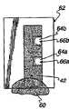
本发明的孔口可以布置成使样品流体沿着特殊的路径且延迟地流过传感器。这种使用方式能有效地改进样品流体与试剂的混合和能更精确地控制流体流过传感器的时间。图5a~5d是具有两个设于交错位置的孔口58以形成样品流体42的曲折路径的传感器56的经时变化图像。图5a示明样品流体42进入传感器56并由孔口58的样品导向边缘44沿流体通道60导引。在图5a中,样品流体42刚进入传感器56且由第一孔口58a的样品导向边缘44导引通过第一电极18。样品流体42的前缘处于第一电极18与第二电极20之间。The orifices of the present invention can be arranged so that the sample fluid flows through the sensor along a specific path and with delay. This mode of use effectively improves the mixing of the sample fluid with the reagents and more precisely controls the timing of the fluid flow through the sensor. 5 a - 5d are time-lapse images of a sensor 56 having two orifices 58 arranged in staggered positions to form a tortuous path for the
然后如图5b所示,样品流体42的前缘46已由第二孔口58b的样品导向边缘44环绕第二孔口58b导引,同时样品流体42与第二电极20接触。此样品流体42继续流过传感器56,如图5c与5d所示,且其前沿在通过传感器56时继续依循流体通道60。The leading
如图5a~5d所示的弯曲通道由于样品流体42沿着流体通道60的迂回加大了扰动,增强了样品流体42与试剂34在传感器56内的混合。此外,由于采用了弯曲的流体通道60而显著增大了时延。例如依据某些实施例的如图5a~5d所示的传感器56可以在流体进入传感器的初始位置和样品流体沿着流体通道完全通过之间延迟一至五秒。流体沿此流体通道流动的时间可以通过窄化或拓宽或是加长或缩短此通道而改变,例如可以将不同尺寸的孔口58设于不同位置来界定这种流体通道。The tortuous channel shown in FIGS. 5 a - 5 d increases the turbulence due to the detour of the
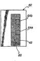
当用到不止一种试剂时,由于不同试剂具有与样品流体的不同最佳反应时间,因而控制流体流过传感器的时间是有利的。在某些光学与电化学的测试应用中可以采用多种试剂。现在参看图6a~f,其中在经时变化图像中示明了具有第一与第二孔口64a与64b来控制流体沿流体通道60流动的传感器62。图6a示明样品流体引入到传感器62之前的传感器62。图6b示明正引入传感器62内的样品流体42。样品流体42的前缘46被样品导向边缘44,沿着流体通道60且围绕第一孔口64a导引。在图6c中,样品流体42的前缘46已通过第一孔口64a且被第二孔口64b的样品导向边缘44导向。When more than one reagent is used, it is advantageous to control the timing of fluid flow through the sensor since different reagents have different optimal reaction times with the sample fluid. A variety of reagents can be used in some optical and electrochemical testing applications. Referring now to Figures 6a-f, a
现在参看图6d,样品流体42已充填流体通道60,并受到外通道边缘(它们在图6a~6f中为隔离边缘52)以及孔口64a与64b的样品导向边缘44的约束。然后如图6e所示,样品流体42充填第一孔口64a下的容积。最后如图6f所示,样品流体42充填第二孔口64b下的容积。若是将试剂供给于两个试剂区66a与66b中(如图6d所示),则图6a~6f所示过程可以用来控制样品流体42与各种试剂的接触时间。Referring now to Figure 6d,
图6a~6f所示的样品流体流动的时间控制有利于其中可能用到具有不同的最佳反应时间的多种被分析物的测试,如血与尿的测试。例如,设第一试剂设于第一试剂区66a,而第二试剂设于第二试剂区66b中,则样品流体42将在其与第二试剂反应之前开始与第一试剂反应,这是由于第一孔口64a的区域要比第二孔口64b的区域更快地被样品流体充满。如同在图4a~4c与5a~5d的实施例中,可以改变流体通道的长度与宽度以及孔口的尺寸与形状来实现所要求的时间控制。根据某些实施例,通过使用用图6a~6f的实施例可以在与试剂区的接触之间取得2~5秒的时延。而通过调节表面性质如试剂的可湿润性则可以实现甚至更长的时延。The time control of sample fluid flow shown in Figures 6a-6f is advantageous for tests where multiple analytes with different optimal reaction times may be used, such as blood and urine tests. For example, if a first reagent is provided in the
通过使第一试剂区的产物扩散到第二试剂区中并用作为第二反应的基底,借助这种方法也可以实现对这种时延的利用。因为时延,可以确定反应产物的浓度。Utilization of this time delay can also be achieved by means of this method by allowing the product of the first reagent zone to diffuse into the second reagent zone and serve as a substrate for the second reaction. Because of the time delay, the concentration of the reaction product can be determined.
图6的实施例的另一种应用是可通过利用相应的多种信号换能元件(包括光束与电极)同时读取多个试剂区。在此实施例中,当同时读取全部的信号换能时,有差异的润湿时间提供了不等的反应时间。Another application of the embodiment of FIG. 6 is that multiple reagent zones can be read simultaneously by utilizing corresponding multiple signal transducing elements (including beams and electrodes). In this embodiment, differential wetting times provide unequal response times when all signal transductions are read simultaneously.
这里以图示的例子详细地描述了本发明的特殊实施例,但本发明是可以有各种变型与其他形式的。应知本发明并不限定于在此所公开的特殊形式中,相反,本发明涵盖了后附权利要求书中所限定的本发明的精神与范围内所有的改型、等效形式与其他可能形式。Specific embodiments of the invention are described in detail herein by way of illustrated examples, but the invention is capable of various modifications and other forms. It should be understood that the invention is not limited to the particular forms disclosed herein, but on the contrary, the invention covers all modifications, equivalent forms and other possibilities within the spirit and scope of the invention as defined in the appended claims. form.
Claims (27)
Applications Claiming Priority (3)
| Application Number | Priority Date | Filing Date | Title |
|---|---|---|---|
| US54234804P | 2004-02-06 | 2004-02-06 | |
| US60/542,348 | 2004-02-06 | ||
| PCT/US2005/003624WO2005078436A1 (en) | 2004-02-06 | 2005-02-04 | Fluid testing sensor having vents for directing fluid flow |
Publications (2)
| Publication Number | Publication Date |
|---|---|
| CN1918470A CN1918470A (en) | 2007-02-21 |
| CN1918470Btrue CN1918470B (en) | 2013-06-19 |
Family
ID=34860288
Family Applications (1)
| Application Number | Title | Priority Date | Filing Date |
|---|---|---|---|
| CN2005800042747AExpired - Fee RelatedCN1918470B (en) | 2004-02-06 | 2005-02-04 | Fluid test sensor with orifice to direct fluid flow |
Country Status (15)
| Country | Link |
|---|---|
| US (1) | US7543481B2 (en) |
| EP (2) | EP2752662B1 (en) |
| JP (1) | JP4662952B2 (en) |
| KR (2) | KR101191093B1 (en) |
| CN (1) | CN1918470B (en) |
| AU (1) | AU2005213658A1 (en) |
| BR (1) | BRPI0507378A (en) |
| CA (1) | CA2553633C (en) |
| CR (1) | CR8599A (en) |
| DK (1) | DK1714147T3 (en) |
| ES (1) | ES2507092T3 (en) |
| MA (1) | MA28352A1 (en) |
| NO (1) | NO20063897L (en) |
| RU (1) | RU2371722C2 (en) |
| WO (1) | WO2005078436A1 (en) |
Families Citing this family (14)
| Publication number | Priority date | Publication date | Assignee | Title |
|---|---|---|---|---|
| WO2005103663A1 (en) | 2004-04-23 | 2005-11-03 | Arkray, Inc. | Analyzer and method of manufacturing the same |
| WO2007133457A2 (en) | 2006-05-08 | 2007-11-22 | Bayer Healthcare Llc | Electrochemical test sensor with reduced sample volume |
| US7797987B2 (en) | 2006-10-11 | 2010-09-21 | Bayer Healthcare Llc | Test sensor with a side vent and method of making the same |
| KR101165200B1 (en)* | 2006-11-10 | 2012-07-17 | 주식회사 인포피아 | Bio-sensor |
| US8080153B2 (en)* | 2007-05-31 | 2011-12-20 | Abbott Diabetes Care Inc. | Analyte determination methods and devices |
| KR101104398B1 (en) | 2009-06-02 | 2012-01-16 | 주식회사 세라젬메디시스 | Apparatus for Measuring Biomaterials and Manufacturing Method Thereof |
| JP5102334B2 (en)* | 2010-06-25 | 2012-12-19 | 日本電波工業株式会社 | Sensing device |
| US9086338B2 (en) | 2010-06-25 | 2015-07-21 | Nihon Dempa Kogyo Co., Ltd. | Sensing device |
| WO2012140888A1 (en) | 2011-04-12 | 2012-10-18 | パナソニック株式会社 | Biosensor and measuring device using same |
| US9733205B2 (en) | 2011-06-16 | 2017-08-15 | Panasonic Healthcare Holdings Co., Ltd. | Sensor and sensor system equipped with same |
| TWI477772B (en)* | 2013-02-25 | 2015-03-21 | Apex Biotechnology Corp | Electrode strip and sensor strip and system thereof |
| BR112015019079A2 (en)* | 2013-03-08 | 2017-07-18 | Halliburton Energy Services Inc | fluid monitoring and control system, method for monitoring a wellbore penetrating an underground formation and method for determining the efficiency of a gas extraction system |
| GB201611442D0 (en) | 2016-06-30 | 2016-08-17 | Lumiradx Tech Ltd | Fluid control |
| TW202136735A (en)* | 2020-01-13 | 2021-10-01 | 英商盧米瑞德克斯英國有限公司 | Fluid control in microfluidic devices |
Citations (6)
| Publication number | Priority date | Publication date | Assignee | Title |
|---|---|---|---|---|
| US5120420A (en)* | 1988-03-31 | 1992-06-09 | Matsushita Electric Industrial Co., Ltd. | Biosensor and a process for preparation thereof |
| EP0537761A2 (en)* | 1991-10-18 | 1993-04-21 | Matsushita Electric Industrial Co., Ltd. | A biosensor and a method for measuring a concentration of a substrate in a sample |
| US5798031A (en)* | 1997-05-12 | 1998-08-25 | Bayer Corporation | Electrochemical biosensor |
| US5846392A (en)* | 1994-03-12 | 1998-12-08 | Knoll; Meinhard | Miniaturized circulatory measuring chamber with integrated chemo- and/or biosensor elements |
| WO2003012421A1 (en)* | 2001-08-01 | 2003-02-13 | Arkray, Inc. | Analyzing implement, analyzing device, and method of manufacturing analyzing implement |
| CN1400466A (en)* | 2001-08-03 | 2003-03-05 | 惠碁生物科技股份有限公司 | Disposable biosensor with spacer layer and method of manufacturing the same |
Family Cites Families (35)
| Publication number | Priority date | Publication date | Assignee | Title |
|---|---|---|---|---|
| US4254083A (en)* | 1979-07-23 | 1981-03-03 | Eastman Kodak Company | Structural configuration for transport of a liquid drop through an ingress aperture |
| JPH0658338B2 (en)* | 1988-05-18 | 1994-08-03 | 松下電器産業株式会社 | Biosensor |
| SE466157B (en)* | 1989-04-25 | 1992-01-07 | Migrata Uk Ltd | DETERMINED TO DETERMINE THE GLUCOSE CONTENT OF WHOLE BLOOD AND DISPOSABLE BEFORE THIS |
| DE59005928D1 (en)* | 1989-11-21 | 1994-07-07 | Bayer Ag | Optical biosensor. |
| US5320732A (en)* | 1990-07-20 | 1994-06-14 | Matsushita Electric Industrial Co., Ltd. | Biosensor and measuring apparatus using the same |
| JP2601075B2 (en)* | 1991-10-21 | 1997-04-16 | 株式会社日立製作所 | Analysis method and analyzer using test piece |
| US5336388A (en)* | 1991-12-26 | 1994-08-09 | Ppg Industries, Inc. | Analyte and pH measuring sensor assembly and method |
| JPH05256811A (en) | 1992-03-13 | 1993-10-08 | Matsushita Electric Ind Co Ltd | Method for manufacturing glucose sensor |
| US5843691A (en)* | 1993-05-15 | 1998-12-01 | Lifescan, Inc. | Visually-readable reagent test strip |
| US5437999A (en)* | 1994-02-22 | 1995-08-01 | Boehringer Mannheim Corporation | Electrochemical sensor |
| DE19539357B4 (en)* | 1994-10-24 | 2011-09-15 | Denso Corporation | Air-fuel ratio detecting means |
| US5582697A (en)* | 1995-03-17 | 1996-12-10 | Matsushita Electric Industrial Co., Ltd. | Biosensor, and a method and a device for quantifying a substrate in a sample liquid using the same |
| US5611999A (en)* | 1995-09-05 | 1997-03-18 | Bayer Corporation | Diffused light reflectance readhead |
| US5518689A (en)* | 1995-09-05 | 1996-05-21 | Bayer Corporation | Diffused light reflectance readhead |
| US5628890A (en)* | 1995-09-27 | 1997-05-13 | Medisense, Inc. | Electrochemical sensor |
| US5755953A (en)* | 1995-12-18 | 1998-05-26 | Abbott Laboratories | Interference free biosensor |
| JP3365184B2 (en)* | 1996-01-10 | 2003-01-08 | 松下電器産業株式会社 | Biosensor |
| US5660791A (en)* | 1996-06-06 | 1997-08-26 | Bayer Corporation | Fluid testing sensor for use in dispensing instrument |
| DE19629656A1 (en)* | 1996-07-23 | 1998-01-29 | Boehringer Mannheim Gmbh | Diagnostic test carrier with multilayer test field and method for the determination of analyte with its aid |
| AU6157898A (en)* | 1997-02-06 | 1998-08-26 | E. Heller & Company | Small volume (in vitro) analyte sensor |
| US5759364A (en)* | 1997-05-02 | 1998-06-02 | Bayer Corporation | Electrochemical biosensor |
| US6129823A (en)* | 1997-09-05 | 2000-10-10 | Abbott Laboratories | Low volume electrochemical sensor |
| US5997817A (en)* | 1997-12-05 | 1999-12-07 | Roche Diagnostics Corporation | Electrochemical biosensor test strip |
| GB2337122B (en)* | 1998-05-08 | 2002-11-13 | Medisense Inc | Test strip |
| CA2305922C (en)* | 1999-08-02 | 2005-09-20 | Bayer Corporation | Improved electrochemical sensor design |
| US6841052B2 (en)* | 1999-08-02 | 2005-01-11 | Bayer Corporation | Electrochemical-sensor design |
| US7073246B2 (en)* | 1999-10-04 | 2006-07-11 | Roche Diagnostics Operations, Inc. | Method of making a biosensor |
| US7122102B2 (en)* | 2001-06-11 | 2006-10-17 | Bayer Healthcare Llc | Electrochemical sensor |
| CA2419213C (en)* | 2002-03-07 | 2011-06-21 | Bayer Healthcare Llc | Improved electrical sensor |
| EP1382968B1 (en)* | 2002-07-18 | 2008-11-19 | Panasonic Corporation | Measuring apparatus with a biosensor |
| JP3910148B2 (en)* | 2003-03-14 | 2007-04-25 | アークレイ株式会社 | Analysis tool with exhaust port |
| US7462265B2 (en)* | 2003-06-06 | 2008-12-09 | Lifescan, Inc. | Reduced volume electrochemical sensor |
| US7544277B2 (en)* | 2003-06-12 | 2009-06-09 | Bayer Healthcare, Llc | Electrochemical test sensors |
| US7138041B2 (en)* | 2004-02-23 | 2006-11-21 | General Life Biotechnology Co., Ltd. | Electrochemical biosensor by screen printing and method of fabricating same |
| US20060070878A1 (en)* | 2004-10-06 | 2006-04-06 | Shu-Mei Wu | Electrochemical biosensor strip |
- 2005
- 2005-02-04KRKR1020067015912Apatent/KR101191093B1/ennot_activeExpired - Fee Related
- 2005-02-04WOPCT/US2005/003624patent/WO2005078436A1/enactiveApplication Filing
- 2005-02-04CACA2553633Apatent/CA2553633C/ennot_activeExpired - Fee Related
- 2005-02-04EPEP14163488.1Apatent/EP2752662B1/ennot_activeExpired - Lifetime
- 2005-02-04AUAU2005213658Apatent/AU2005213658A1/ennot_activeAbandoned
- 2005-02-04USUS10/590,838patent/US7543481B2/ennot_activeExpired - Fee Related
- 2005-02-04RURU2006132053/28Apatent/RU2371722C2/ennot_activeIP Right Cessation
- 2005-02-04KRKR1020127016385Apatent/KR20120101692A/ennot_activeWithdrawn
- 2005-02-04JPJP2006552280Apatent/JP4662952B2/ennot_activeExpired - Lifetime
- 2005-02-04BRBRPI0507378-2Apatent/BRPI0507378A/ennot_activeApplication Discontinuation
- 2005-02-04ESES05712900.9Tpatent/ES2507092T3/ennot_activeExpired - Lifetime
- 2005-02-04EPEP05712900.9Apatent/EP1714147B1/ennot_activeExpired - Lifetime
- 2005-02-04CNCN2005800042747Apatent/CN1918470B/ennot_activeExpired - Fee Related
- 2005-02-04DKDK05712900.9Tpatent/DK1714147T3/enactive
- 2006
- 2006-08-07MAMA29248Apatent/MA28352A1/enunknown
- 2006-09-01NONO20063897Apatent/NO20063897L/ennot_activeApplication Discontinuation
- 2006-09-06CRCR8599Apatent/CR8599A/ennot_activeApplication Discontinuation
Patent Citations (7)
| Publication number | Priority date | Publication date | Assignee | Title |
|---|---|---|---|---|
| US5120420A (en)* | 1988-03-31 | 1992-06-09 | Matsushita Electric Industrial Co., Ltd. | Biosensor and a process for preparation thereof |
| US5120420B1 (en)* | 1988-03-31 | 1999-11-09 | Matsushita Electric Industrial Co Ltd | Biosensor and a process for preparation thereof |
| EP0537761A2 (en)* | 1991-10-18 | 1993-04-21 | Matsushita Electric Industrial Co., Ltd. | A biosensor and a method for measuring a concentration of a substrate in a sample |
| US5846392A (en)* | 1994-03-12 | 1998-12-08 | Knoll; Meinhard | Miniaturized circulatory measuring chamber with integrated chemo- and/or biosensor elements |
| US5798031A (en)* | 1997-05-12 | 1998-08-25 | Bayer Corporation | Electrochemical biosensor |
| WO2003012421A1 (en)* | 2001-08-01 | 2003-02-13 | Arkray, Inc. | Analyzing implement, analyzing device, and method of manufacturing analyzing implement |
| CN1400466A (en)* | 2001-08-03 | 2003-03-05 | 惠碁生物科技股份有限公司 | Disposable biosensor with spacer layer and method of manufacturing the same |
Also Published As
| Publication number | Publication date |
|---|---|
| NO20063897L (en) | 2006-09-01 |
| EP1714147B1 (en) | 2014-07-23 |
| CA2553633C (en) | 2012-10-16 |
| KR20120101692A (en) | 2012-09-14 |
| KR20060131837A (en) | 2006-12-20 |
| WO2005078436A1 (en) | 2005-08-25 |
| EP2752662A1 (en) | 2014-07-09 |
| JP4662952B2 (en) | 2011-03-30 |
| CN1918470A (en) | 2007-02-21 |
| JP2007521498A (en) | 2007-08-02 |
| MA28352A1 (en) | 2006-12-01 |
| RU2371722C2 (en) | 2009-10-27 |
| US7543481B2 (en) | 2009-06-09 |
| HK1100496A1 (en) | 2007-09-21 |
| KR101191093B1 (en) | 2012-10-15 |
| RU2006132053A (en) | 2008-03-20 |
| ES2507092T3 (en) | 2014-10-14 |
| DK1714147T3 (en) | 2014-10-13 |
| CA2553633A1 (en) | 2005-08-25 |
| CR8599A (en) | 2007-09-07 |
| EP1714147A1 (en) | 2006-10-25 |
| EP2752662B1 (en) | 2020-01-29 |
| BRPI0507378A (en) | 2007-07-10 |
| AU2005213658A1 (en) | 2005-08-25 |
| US20070062262A1 (en) | 2007-03-22 |
Similar Documents
| Publication | Publication Date | Title |
|---|---|---|
| CN1918470B (en) | Fluid test sensor with orifice to direct fluid flow | |
| EP0830206B1 (en) | Test strip holder and method of use | |
| CN1839313B (en) | Devices and methods involving electrochemical biosensors | |
| US6572745B2 (en) | Electrochemical sensor and method thereof | |
| US7967962B2 (en) | Sensors | |
| US6821400B2 (en) | Electrochemical sensor with increased reproducibility | |
| US9347909B2 (en) | Sample-retainable biosensor test strip | |
| JP2004132961A (en) | Testing equipment for analyzing biological sample liquids | |
| JP5343258B2 (en) | Biosensor for measuring biological materials | |
| EP1070541A2 (en) | Apparatus for collecting a liquid sample | |
| US20080044842A1 (en) | Biological Test Strip | |
| MXPA06008845A (en) | Fluid testing sensor having vents for directing fluid flow | |
| JP5086493B2 (en) | Apparatus for measuring biological material and method for manufacturing the same | |
| HK1100496B (en) | Fluid testing sensor having vents for directing fluid flow | |
| EP3822634B1 (en) | Biosensor strip | |
| JP2013530409A (en) | Test strip for body fluid sample detection | |
| US8501111B2 (en) | Small volume and fast acting optical analyte sensor |
Legal Events
| Date | Code | Title | Description |
|---|---|---|---|
| C06 | Publication | ||
| PB01 | Publication | ||
| C10 | Entry into substantive examination | ||
| SE01 | Entry into force of request for substantive examination | ||
| REG | Reference to a national code | Ref country code:HK Ref legal event code:DE Ref document number:1100496 Country of ref document:HK | |
| C14 | Grant of patent or utility model | ||
| GR01 | Patent grant | ||
| REG | Reference to a national code | Ref country code:HK Ref legal event code:GR Ref document number:1100496 Country of ref document:HK | |
| CF01 | Termination of patent right due to non-payment of annual fee | Granted publication date:20130619 | |
| CF01 | Termination of patent right due to non-payment of annual fee |