CN1909859B - Ocular Compound Microcannula - Google Patents
Ocular Compound MicrocannulaDownload PDFInfo
- Publication number
- CN1909859B CN1909859BCN2005800030190ACN200580003019ACN1909859BCN 1909859 BCN1909859 BCN 1909859BCN 2005800030190 ACN2005800030190 ACN 2005800030190ACN 200580003019 ACN200580003019 ACN 200580003019ACN 1909859 BCN1909859 BCN 1909859B
- Authority
- CN
- China
- Prior art keywords
- microcannula
- connecting element
- distal end
- reinforcing element
- reinforcing
- Prior art date
- Legal status (The legal status is an assumption and is not a legal conclusion. Google has not performed a legal analysis and makes no representation as to the accuracy of the status listed.)
- Expired - Lifetime
Links
- 150000001875compoundsChemical class0.000titleclaimsdescription30
- 239000000463materialSubstances0.000claimsabstractdescription25
- 230000003014reinforcing effectEffects0.000claimsabstractdescription20
- 239000002131composite materialSubstances0.000claimsabstractdescription16
- 210000001519tissueAnatomy0.000claimsdescription18
- 239000013307optical fiberSubstances0.000claimsdescription17
- 229910052751metalInorganic materials0.000claimsdescription14
- 239000002184metalSubstances0.000claimsdescription14
- 239000012530fluidSubstances0.000claimsdescription12
- 238000005452bendingMethods0.000claimsdescription11
- 239000011248coating agentSubstances0.000claimsdescription6
- 238000000576coating methodMethods0.000claimsdescription6
- 239000000853adhesiveSubstances0.000claimsdescription5
- 230000001070adhesive effectEffects0.000claimsdescription5
- 210000001742aqueous humorAnatomy0.000claimsdescription5
- 229920005570flexible polymerPolymers0.000claimsdescription5
- 238000003384imaging methodMethods0.000claimsdescription5
- 230000001050lubricating effectEffects0.000claimsdescription4
- 210000001210retinal vesselAnatomy0.000claimsdescription3
- 238000001356surgical procedureMethods0.000claimsdescription3
- 208000024304Choroidal EffusionsDiseases0.000claims2
- 238000003780insertionMethods0.000claims2
- 230000037431insertionEffects0.000claims2
- 238000007493shaping processMethods0.000claims2
- 238000012800visualizationMethods0.000claims1
- 238000013461designMethods0.000abstractdescription9
- 238000002560therapeutic procedureMethods0.000abstractdescription2
- 238000013459approachMethods0.000abstract1
- 239000007788liquidSubstances0.000description37
- 230000008520organizationEffects0.000description28
- 210000001508eyeAnatomy0.000description27
- 238000000034methodMethods0.000description22
- 241000463219EpithecaSpecies0.000description21
- 230000002708enhancing effectEffects0.000description20
- 229920000642polymerPolymers0.000description18
- 238000012360testing methodMethods0.000description17
- 239000013308plastic optical fiberSubstances0.000description12
- 229920002614Polyether block amidePolymers0.000description11
- 239000010959steelSubstances0.000description8
- 229910000831SteelInorganic materials0.000description7
- 239000011230binding agentSubstances0.000description7
- -1energySubstances0.000description7
- 230000008569processEffects0.000description7
- 238000005728strengtheningMethods0.000description7
- 229920000139polyethylene terephthalatePolymers0.000description6
- 239000005020polyethylene terephthalateSubstances0.000description6
- 239000000835fiberSubstances0.000description5
- 229940089982healonDrugs0.000description5
- YWIVKILSMZOHHF-QJZPQSOGSA-Nsodium;(2s,3s,4s,5r,6r)-6-[(2s,3r,4r,5s,6r)-3-acetamido-2-[(2s,3s,4r,5r,6r)-6-[(2r,3r,4r,5s,6r)-3-acetamido-2,5-dihydroxy-6-(hydroxymethyl)oxan-4-yl]oxy-2-carboxy-4,5-dihydroxyoxan-3-yl]oxy-5-hydroxy-6-(hydroxymethyl)oxan-4-yl]oxy-3,4,5-trihydroxyoxane-2-Chemical compound[Na+].CC(=O)N[C@H]1[C@H](O)O[C@H](CO)[C@@H](O)[C@@H]1O[C@H]1[C@H](O)[C@@H](O)[C@H](O[C@H]2[C@@H]([C@@H](O[C@H]3[C@@H]([C@@H](O)[C@H](O)[C@H](O3)C(O)=O)O)[C@H](O)[C@@H](CO)O2)NC(C)=O)[C@@H](C(O)=O)O1YWIVKILSMZOHHF-QJZPQSOGSA-N0.000description5
- 210000000398surgical flapAnatomy0.000description5
- KIUKXJAPPMFGSW-DNGZLQJQSA-N(2S,3S,4S,5R,6R)-6-[(2S,3R,4R,5S,6R)-3-Acetamido-2-[(2S,3S,4R,5R,6R)-6-[(2R,3R,4R,5S,6R)-3-acetamido-2,5-dihydroxy-6-(hydroxymethyl)oxan-4-yl]oxy-2-carboxy-4,5-dihydroxyoxan-3-yl]oxy-5-hydroxy-6-(hydroxymethyl)oxan-4-yl]oxy-3,4,5-trihydroxyoxane-2-carboxylic acidChemical compoundCC(=O)N[C@H]1[C@H](O)O[C@H](CO)[C@@H](O)[C@@H]1O[C@H]1[C@H](O)[C@@H](O)[C@H](O[C@H]2[C@@H]([C@@H](O[C@H]3[C@@H]([C@@H](O)[C@H](O)[C@H](O3)C(O)=O)O)[C@H](O)[C@@H](CO)O2)NC(C)=O)[C@@H](C(O)=O)O1KIUKXJAPPMFGSW-DNGZLQJQSA-N0.000description4
- 238000006243chemical reactionMethods0.000description4
- 229920002674hyaluronanPolymers0.000description4
- 229960003160hyaluronic acidDrugs0.000description4
- 239000004642PolyimideSubstances0.000description3
- 210000004027cellAnatomy0.000description3
- 238000001514detection methodMethods0.000description3
- 239000000499gelSubstances0.000description3
- 230000008676importEffects0.000description3
- 239000000203mixtureSubstances0.000description3
- 229920001721polyimidePolymers0.000description3
- 210000003786scleraAnatomy0.000description3
- 239000004696Poly ether ether ketoneSubstances0.000description2
- 239000004952PolyamideSubstances0.000description2
- 101100408811Schizosaccharomyces pombe (strain 972 / ATCC 24843) pof9 geneProteins0.000description2
- 230000015572biosynthetic processEffects0.000description2
- 210000005252bulbus oculiAnatomy0.000description2
- 239000000919ceramicSubstances0.000description2
- 230000008859changeEffects0.000description2
- 210000004087corneaAnatomy0.000description2
- LOKCTEFSRHRXRJ-UHFFFAOYSA-Idipotassium trisodium dihydrogen phosphate hydrogen phosphate dichlorideChemical compoundP(=O)(O)(O)[O-].[K+].P(=O)(O)([O-])[O-].[Na+].[Na+].[Cl-].[K+].[Cl-].[Na+]LOKCTEFSRHRXRJ-UHFFFAOYSA-I0.000description2
- 238000000605extractionMethods0.000description2
- 239000002654heat shrinkable materialSubstances0.000description2
- 239000002953phosphate buffered salineSubstances0.000description2
- 229920002492poly(sulfone)Polymers0.000description2
- 229920002647polyamidePolymers0.000description2
- 229920002530polyetherether ketonePolymers0.000description2
- 230000002787reinforcementEffects0.000description2
- 239000000243solutionSubstances0.000description2
- 238000010254subcutaneous injectionMethods0.000description2
- 239000007929subcutaneous injectionSubstances0.000description2
- 230000009466transformationEffects0.000description2
- 210000005239tubuleAnatomy0.000description2
- 239000003190viscoelastic substanceSubstances0.000description2
- 239000010963304 stainless steelSubstances0.000description1
- 229910001316Ag alloyInorganic materials0.000description1
- 229910000851Alloy steelInorganic materials0.000description1
- OKTJSMMVPCPJKN-UHFFFAOYSA-NCarbonChemical compound[C]OKTJSMMVPCPJKN-UHFFFAOYSA-N0.000description1
- 229920000965DuroplastPolymers0.000description1
- 239000004593EpoxySubstances0.000description1
- 208000010412GlaucomaDiseases0.000description1
- 206010020751HypersensitivityDiseases0.000description1
- 239000004698PolyethyleneSubstances0.000description1
- 239000004743PolypropyleneSubstances0.000description1
- 239000004793PolystyreneSubstances0.000description1
- 229910001260Pt alloyInorganic materials0.000description1
- 229910000589SAE 304 stainless steelInorganic materials0.000description1
- 239000004699Ultra-high molecular weight polyethyleneSubstances0.000description1
- 239000011149active materialSubstances0.000description1
- 208000026935allergic diseaseDiseases0.000description1
- 229910045601alloyInorganic materials0.000description1
- 239000000956alloySubstances0.000description1
- 230000000712assemblyEffects0.000description1
- 238000000429assemblyMethods0.000description1
- 201000009310astigmatismDiseases0.000description1
- 230000006399behaviorEffects0.000description1
- 210000004204blood vesselAnatomy0.000description1
- 210000001124body fluidAnatomy0.000description1
- 239000010839body fluidSubstances0.000description1
- 229910052799carbonInorganic materials0.000description1
- 239000000470constituentSubstances0.000description1
- 238000010276constructionMethods0.000description1
- 230000008602contractionEffects0.000description1
- 230000008878couplingEffects0.000description1
- 238000010168coupling processMethods0.000description1
- 238000005859coupling reactionMethods0.000description1
- 230000007547defectEffects0.000description1
- 230000007850degenerationEffects0.000description1
- 238000006073displacement reactionMethods0.000description1
- 239000003814drugSubstances0.000description1
- 230000000694effectsEffects0.000description1
- 229920001971elastomerPolymers0.000description1
- 239000000806elastomerSubstances0.000description1
- 238000005516engineering processMethods0.000description1
- 238000011156evaluationMethods0.000description1
- 239000004811fluoropolymerSubstances0.000description1
- 229920002313fluoropolymerPolymers0.000description1
- 238000002594fluoroscopyMethods0.000description1
- 238000009432framingMethods0.000description1
- 229910052736halogenInorganic materials0.000description1
- 150000002367halogensChemical class0.000description1
- 238000010438heat treatmentMethods0.000description1
- 230000009610hypersensitivityEffects0.000description1
- 239000007943implantSubstances0.000description1
- 238000003331infrared imagingMethods0.000description1
- 230000004410intraocular pressureEffects0.000description1
- 210000001503jointAnatomy0.000description1
- 239000006210lotionSubstances0.000description1
- 239000000314lubricantSubstances0.000description1
- 238000005461lubricationMethods0.000description1
- 230000007246mechanismEffects0.000description1
- 229910001092metal group alloyInorganic materials0.000description1
- 238000002406microsurgeryMethods0.000description1
- 238000002324minimally invasive surgeryMethods0.000description1
- 238000002156mixingMethods0.000description1
- 229910001000nickel titaniumInorganic materials0.000description1
- HLXZNVUGXRDIFK-UHFFFAOYSA-Nnickel titaniumChemical compound[Ti].[Ti].[Ti].[Ti].[Ti].[Ti].[Ti].[Ti].[Ti].[Ti].[Ti].[Ni].[Ni].[Ni].[Ni].[Ni].[Ni].[Ni].[Ni].[Ni].[Ni].[Ni].[Ni].[Ni].[Ni]HLXZNVUGXRDIFK-UHFFFAOYSA-N0.000description1
- 230000010412perfusionEffects0.000description1
- 229920003229poly(methyl methacrylate)Polymers0.000description1
- 229920000573polyethylenePolymers0.000description1
- 239000004926polymethyl methacrylateSubstances0.000description1
- 229920001155polypropylenePolymers0.000description1
- 229920005553polystyrene-acrylatePolymers0.000description1
- 108090000765processed proteins & peptidesProteins0.000description1
- 238000012545processingMethods0.000description1
- 230000000750progressive effectEffects0.000description1
- 230000001737promoting effectEffects0.000description1
- 238000011084recoveryMethods0.000description1
- 238000011160researchMethods0.000description1
- 210000001957retinal veinAnatomy0.000description1
- 238000009738saturatingMethods0.000description1
- 238000007789sealingMethods0.000description1
- 239000004332silverSubstances0.000description1
- 210000004872soft tissueAnatomy0.000description1
- 239000010935stainless steelSubstances0.000description1
- 229910001220stainless steelInorganic materials0.000description1
- 239000000126substanceSubstances0.000description1
- 238000004381surface treatmentMethods0.000description1
- 229940124597therapeutic agentDrugs0.000description1
- 238000012546transferMethods0.000description1
- 229920000785ultra high molecular weight polyethylenePolymers0.000description1
- 210000003462veinAnatomy0.000description1
- 230000000007visual effectEffects0.000description1
- 238000004804windingMethods0.000description1
Images
Classifications
- A—HUMAN NECESSITIES
- A61—MEDICAL OR VETERINARY SCIENCE; HYGIENE
- A61F—FILTERS IMPLANTABLE INTO BLOOD VESSELS; PROSTHESES; DEVICES PROVIDING PATENCY TO, OR PREVENTING COLLAPSING OF, TUBULAR STRUCTURES OF THE BODY, e.g. STENTS; ORTHOPAEDIC, NURSING OR CONTRACEPTIVE DEVICES; FOMENTATION; TREATMENT OR PROTECTION OF EYES OR EARS; BANDAGES, DRESSINGS OR ABSORBENT PADS; FIRST-AID KITS
- A61F9/00—Methods or devices for treatment of the eyes; Devices for putting in contact-lenses; Devices to correct squinting; Apparatus to guide the blind; Protective devices for the eyes, carried on the body or in the hand
- A61F9/007—Methods or devices for eye surgery
- A61F9/00781—Apparatus for modifying intraocular pressure, e.g. for glaucoma treatment
- A—HUMAN NECESSITIES
- A61—MEDICAL OR VETERINARY SCIENCE; HYGIENE
- A61B—DIAGNOSIS; SURGERY; IDENTIFICATION
- A61B3/00—Apparatus for testing the eyes; Instruments for examining the eyes
- A61B3/0008—Apparatus for testing the eyes; Instruments for examining the eyes provided with illuminating means
- A—HUMAN NECESSITIES
- A61—MEDICAL OR VETERINARY SCIENCE; HYGIENE
- A61F—FILTERS IMPLANTABLE INTO BLOOD VESSELS; PROSTHESES; DEVICES PROVIDING PATENCY TO, OR PREVENTING COLLAPSING OF, TUBULAR STRUCTURES OF THE BODY, e.g. STENTS; ORTHOPAEDIC, NURSING OR CONTRACEPTIVE DEVICES; FOMENTATION; TREATMENT OR PROTECTION OF EYES OR EARS; BANDAGES, DRESSINGS OR ABSORBENT PADS; FIRST-AID KITS
- A61F9/00—Methods or devices for treatment of the eyes; Devices for putting in contact-lenses; Devices to correct squinting; Apparatus to guide the blind; Protective devices for the eyes, carried on the body or in the hand
- A61F9/007—Methods or devices for eye surgery
- A—HUMAN NECESSITIES
- A61—MEDICAL OR VETERINARY SCIENCE; HYGIENE
- A61M—DEVICES FOR INTRODUCING MEDIA INTO, OR ONTO, THE BODY; DEVICES FOR TRANSDUCING BODY MEDIA OR FOR TAKING MEDIA FROM THE BODY; DEVICES FOR PRODUCING OR ENDING SLEEP OR STUPOR
- A61M27/00—Drainage appliance for wounds or the like, i.e. wound drains, implanted drains
- A—HUMAN NECESSITIES
- A61—MEDICAL OR VETERINARY SCIENCE; HYGIENE
- A61B—DIAGNOSIS; SURGERY; IDENTIFICATION
- A61B17/00—Surgical instruments, devices or methods
- A61B17/34—Trocars; Puncturing needles
- A61B17/3417—Details of tips or shafts, e.g. grooves, expandable, bendable; Multiple coaxial sliding cannulas, e.g. for dilating
- A61B17/3421—Cannulas
- A—HUMAN NECESSITIES
- A61—MEDICAL OR VETERINARY SCIENCE; HYGIENE
- A61M—DEVICES FOR INTRODUCING MEDIA INTO, OR ONTO, THE BODY; DEVICES FOR TRANSDUCING BODY MEDIA OR FOR TAKING MEDIA FROM THE BODY; DEVICES FOR PRODUCING OR ENDING SLEEP OR STUPOR
- A61M25/00—Catheters; Hollow probes
- A61M25/0021—Catheters; Hollow probes characterised by the form of the tubing
- A61M2025/0042—Microcatheters, cannula or the like having outside diameters around 1 mm or less
- A—HUMAN NECESSITIES
- A61—MEDICAL OR VETERINARY SCIENCE; HYGIENE
- A61M—DEVICES FOR INTRODUCING MEDIA INTO, OR ONTO, THE BODY; DEVICES FOR TRANSDUCING BODY MEDIA OR FOR TAKING MEDIA FROM THE BODY; DEVICES FOR PRODUCING OR ENDING SLEEP OR STUPOR
- A61M25/00—Catheters; Hollow probes
- A61M25/0043—Catheters; Hollow probes characterised by structural features
- A61M25/005—Catheters; Hollow probes characterised by structural features with embedded materials for reinforcement, e.g. wires, coils, braids
Landscapes
- Health & Medical Sciences (AREA)
- Life Sciences & Earth Sciences (AREA)
- Ophthalmology & Optometry (AREA)
- Veterinary Medicine (AREA)
- Engineering & Computer Science (AREA)
- Biomedical Technology (AREA)
- Heart & Thoracic Surgery (AREA)
- Animal Behavior & Ethology (AREA)
- General Health & Medical Sciences (AREA)
- Public Health (AREA)
- Surgery (AREA)
- Vascular Medicine (AREA)
- Nuclear Medicine, Radiotherapy & Molecular Imaging (AREA)
- Biophysics (AREA)
- Physics & Mathematics (AREA)
- Medical Informatics (AREA)
- Molecular Biology (AREA)
- Otolaryngology (AREA)
- Anesthesiology (AREA)
- Hematology (AREA)
- Media Introduction/Drainage Providing Device (AREA)
- Materials For Medical Uses (AREA)
- Prostheses (AREA)
- Pharmaceuticals Containing Other Organic And Inorganic Compounds (AREA)
- Acyclic And Carbocyclic Compounds In Medicinal Compositions (AREA)
- Optical Couplings Of Light Guides (AREA)
Abstract
Translated fromChinese
Description
Invention field
The present invention relates to microcannula, described microcannula is made of the multicompartment of composite design.Described composite design makes this microcannula have variable machinery and delivery characteristics, thereby can carry out eye treatment by Wicresoft (minimallyinvasive) method.
Background of invention
A lot of conduits and intubate are used in the eye surgical operation, are used for delivering liquid, gas, suction and energy to selected ocular.Existing intubate normally is connected in one section straight or curved duroplasts or metal tube of joint.In the process of the better operated eye Therapeutic Method of research, need a kind of intubate of very little structure of eye and passage that enters into to carry out Minimally Invasive Surgery.This enter and continue to be inserted into crooked or zigzag space for example the microcannula in schlemm's canal or the little blood vessel both needed flexibility also to need " propelling property ", and its diameter will remain in the scope of 50-350 micron.Microcannula of the present invention is made of the multicompartment of composite design.Described composite design makes this microcannula have variable machinery and delivery characteristics, thereby can carry out eye treatment by invasive methods.
Prior art:
United States Patent (USP) 6,524,275
Lynch etc., on February 25th, 2003
Treat glaucomatous inflatable device and method
United States Patent (USP) 6,355,027
Le etc., on March 12nd, 2002
The flexible miniature intubate
United States Patent (USP) 6,142,990
Burk, on November 7th, 2000
Medical apparatus is particularly useful for reducing intraocular pressure
United States Patent (USP) 6,036,670
Wijeratne etc., on March 14th, 2000
Conversion balloon catheter, molectron and the method for curling
United States Patent (USP) 5,911,715
Berg etc., on June 15th, 1999
Conduit with selected bending modulus section
United States Patent (USP) 5,791,036
Goodin etc., on August 11st, 1998
The conduit converting system
United States Patent (USP) 5,569,218
Berg on October 29th, 1996
The elastic catheter conversion element
United States Patent (USP) 5,486,165
Stegmann on January 23rd, 1996
Be used to keep the method and apparatus of normal intra-ocular tension
United States Patent (USP) 5,308,342
Sepetka etc., on May 3rd, 1994
The conduit that rigidity is variable
The patent No.: EP 1114627 A1
Inventor: Grieshaber Hans R (Ch); Stegmann Robert Prof M D (Za)
Improve the method and apparatus of the outflow situation of eyes aqueous humor
The patent No.: W00064389
Inventor: Brown Reay H (Us); Lynch Mary G (Us); King Spencer B lii (Us)
Treat glaucomatous girder and cut apparatus and method
The patent No.: W002074052
Inventor: Smedley Gregory T; Gharib Morteza; Tu Hosheng
The eye lotion dropper (applicator) and the method that the girder diverter are used for glaucoma treatment
The patent No.: W003/045290
Inventor: Conston S, Yamamoto R
The eye microsurgical system
The patent No.: W02004/093761
Inventor: Conston S, Kupiecki D, McKenzie J, Yamamoto R
The eye microsurgery instruments
Summary of the invention
The present invention relates to a kind of compound microcannula, be used for inserting and continuing to enter into the organization space of eye, described microcannula comprises: at least one external diameter be equal to or less than 350 microns, the flexible tubular Connection Element, this element has near-end and far-end, and this element is fit to place organization space; Proximal joint is used for transfer material, energy and instrument; And the enhancing element that links to each other with Connection Element.
The invention still further relates to a kind of microcannula that strengthens element that has, described enhancing element provides higher axial and flexural rigidity for the near-end of microcannula, for far-end provides lower axial and flexural rigidity.
The invention still further relates to a kind of microcannula that strengthens element that has, described enhancing element is made of metal.
The invention still further relates to a kind of microcannula that has Connection Element and strengthen element, described Connection Element is made by flexible polymer, and described enhancing element is made of metal.
The invention still further relates to a kind of microcannula with two or more Connection Elements.
The invention still further relates to a kind of microcannula with Connection Element of concentric arrangement.
The invention still further relates to a kind of microcannula with the Connection Element that is arranged in parallel.
The invention still further relates to a kind of microcannula that comprises two Connection Elements, wherein second Connection Element is positioned at the intracavity of first Connection Element.
The invention still further relates to a kind of microcannula with two or more enhancing elements.
The invention still further relates to a kind of microcannula with enhancing element of coil form.
The invention still further relates to a kind of microcannula that strengthens element that has, described enhancing element is tapered towards the far-end of microcannula.
The invention still further relates to a kind of microcannula with Connection Element, described Connection Element is made by one section conduit (tubing), optical fiber or electric lead.
The invention still further relates to a kind of microcannula, described microcannula is designed to be fit to place schlemm's canal, aqueous humor collecting tubule, aqueous veins, perichoroid space or the retinal vessel of organization space such as eyes.
The invention still further relates to a kind of microcannula, described microcannula has the forward position and is circular far-end.
The invention still further relates to a kind of microcannula that has Connection Element and strengthen element, described Connection Element is connected by epitheca with the enhancing element.
The invention still further relates to a kind of microcannula with epitheca, described epitheca is made of the heat-shrinkable conduit.
The invention still further relates to a kind of microcannula with epitheca, described epitheca heat is blended in Connection Element.
The invention still further relates to a kind of microcannula that has Connection Element and strengthen element, described Connection Element is connected by binding agent with the enhancing element.
The invention still further relates to a kind of microcannula that has Connection Element and strengthen element, described Connection Element and strengthen element and link together by non-adhesive means such as thermal weld or ultra-sonic welded.
The present invention relates to a kind of compound microcannula, be used for entering and continuing to be inserted into the organization space of eyes, described microcannula comprises: at least one external diameter be equal to or less than 350 microns, the flexible tubular Connection Element, it has near-end and far-end, and it is fit to place organization space; Be connected in the curling metal reinforcement element of Connection Element; Wherein said Connection Element is made by flexible polymer or superelastic metal alloy.
The present invention relates to a kind of compound microcannula, be used for entering and continuing to be inserted into the organization space of eyes, described microcannula comprises: at least one external diameter be equal to or less than 350 microns, the flexible tubular Connection Element, it has near-end and far-end, and it has the liquid connection chamber that is fit to place organization space; Be used to import the proximal joint of liquid and comprise fibre-optic second Connection Element, wherein said microcannula provides a kind of method that simultaneously liquid and visible light signal is delivered to the microcannula far-end.
The present invention relates to a kind of compound microcannula, be used for entering and continuing to be inserted into the organization space of eyes, described microcannula comprises: at least one external diameter be equal to or less than 350 microns, the flexible tubular Connection Element, it has near-end and far-end, and it has the liquid connection chamber that is fit to place organization space; Be used to import the proximal joint of liquid and comprise fibre-optic second Connection Element, wherein said microcannula has circular far-end, and a kind of method that simultaneously liquid and visible light signal is delivered to the microcannula far-end is provided.
The present invention relates to a kind of compound microcannula, be used for entering and continuing to be inserted into the organization space of eyes, described microcannula comprises: at least one external diameter be equal to or less than 350 microns, the flexible tubular Connection Element, it has near-end and far-end, and it has the liquid connection chamber that is fit to place organization space; Be used to import the proximal joint of liquid and comprise fibre-optic second Connection Element, and strengthen element, wherein said microcannula provides a kind of method that simultaneously liquid and visible light signal is delivered to the microcannula far-end.
The accompanying drawing summary
Fig. 1 is the sectional view that strengthens the gradually thin compound microcannula of element.
Fig. 2 has two sectional views that strengthen the compound microcannula of element, and two of strengthening in the element are total lengths, and another is the part of total length.
Fig. 3 is the partial cross sectional view of a compound microcannula, and this microcannula has the enhancing element that circular wire form spiral twines.
Fig. 4 is the partial cross sectional view of a compound microcannula, and this microcannula has the enhancing element that flat belt-like form spiral twines.
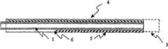
Fig. 5 is the side view and the close-up view of the compound microcannula of a bending, and the signal indicator of this microcannula stretches out the far-end of epitheca.
Fig. 6 is the cross-sectional view of a compound microcannula, and this microcannula has gradually thin enhancing element and circular far-end.
Fig. 7 is the cross-sectional view of a compound microcannula, and this microcannula has with Connection Element and optical fiber and separates the spherical far-end that forms, with at this end parts astigmatism index signal.
Detailed Description Of The Invention
The present invention includes a kind of microcannula, it is designed to can enter into very little organization space in surgical operation.Especially for operated eye, described microcannula can be used for being inserted in schlemm's canal, aqueous humor collecting tubule, aqueous veins, retinal vein and the perichoroid space.Therefore the diameter of these structures is the 50-250 micron, also the external diameter of microcannula has been limited in similar size.As shown in Figure 1, described microcannula comprises flexible elongated elements, at its near-end 3 joint is arranged, and it also comprises far-end, and the interface channel between far-end and the near-end 1.The interface channel 1 of microcannula can be used for that liquid, material, energy, gas, suction, operation tool and implant are delivered to the far-end surgical site and is used for multiple surgical tasks.Interface channel 1 can be the chamber of tubulose elongated elements to carry material, can be optical fiber carrying light energy, or electric wire be to carry the signal of telecommunication.Elongate flexible element with interface channel 1 is called Connection Element.A Connection Element can have more than one interface channel.
Microcannula of the present invention has mixed special design feature, and it can be put in the very little organization space.The feature of a key is to have adopted compound microcannula design, and it has the appropriate combination of axial stiffness and compliance.Wish that microcannula is flexible, so that it can enter along organization space bending or zigzag, and the damage that tissue is caused is very little, and promoting the progressive strength of microcannula but it will have enough axial stiffness or " propelling property " can transmit.For certain fixed external diameter, can customize its mechanical property by constituent material and the cross sectional dimensions of selecting microcannula.In one embodiment, strengthen the outside that element 2 is connected to Connection Element.Usually, strengthen the material that element 2 contains and have higher bending modulus than Connection Element.Connection Element can be thin-walled polymer or metal tube.Strengthening element 2 can be made by any high modulus material, such as but not limited to, metal comprises rustless steel and Nitinol, ceramic fibre and high modulus polymer, filling or enhanced polymer, and the complex of polymer-polymer.
For for the best applications in the cell space, the far-end of wishing microcannula is flexible, but the more rigidity that becomes from distal-to-proximal its mechanical performance.This transformation can comprise the one or more steps or the compliance gradient of the mechanical compliance on the microcannula length.This mechanicalness conversion of energy can change its cross-sectional area or material character by the length along microcannula, mix one or more increases inflexible element or its and makes up and realize.As shown in Figure 2, in an embodiment of the invention, microcannula has Connection Element 1 and forms interface channel 1, and it is made by flexible polymer, is connected with two along the length of Connection Element 1 and strengthens elements 4,5.One of them strengthens element, strengthens element 5, extend along Connection Element, but do not extend to far-end fully, and another enhancing element 4 extends to far-end fully so that the transformation of crooked compliance to be provided.Strengthening element 4,5 can be made by high modulus polymer or metal.In a similar embodiment, available one has the enhancing element that flexural rigidity changes, as gradually thin line 2, strengthens Connection Element.Perhaps, strengthening element can be made of the successive section of different modulus and cross sectional dimensions.Available epitheca 6 will strengthen element and be fixed in its position, and described epitheca 6 can comprise tightness (tight fitting) polymer pipe or polymer contraction pipe.Perhaps, strengthen element and can adhere to or be incorporated into Connection Element, or can all or part ofly be included in the Connection Element.
Strengthening element and also can prevent the Connection Element knot. this is for using high modulus polymer, the Connection Element of making as polyimides, polysulfones, ultra-high molecular weight polyethylene and fibre reinforced polymeric complex (fiber reinforced polymercomposites) is particularly useful, the Connection Element that these materials are made is knot or degeneration when high capacity amount (loads), causes permanent mechanical defect.Strengthen element and also can comprise the ductility material, make the shape of microcannula can carry out manual setting to adapt to the curved shape of organization space better.The possible ductility material that is used to strengthen element includes but not limited to steel, silver and platinum alloy.
Shown in Fig. 3 and 4, the reinforcement of Connection Element also can realize so that high crooked compliance and high axial stiffness (thereby having increased propelling property) to be provided by mixing the piped element of spiral shell.The enhancing element 7 and 8 that is connected in epitheca can be element spiral or that twine, is positioned on the outer surface of epitheca or is formed among the outer surface.Strengthening element 7 and 8 can be any suitable high modulus material, such as but not limited to, metal such as rustless steel, peptide and superelastic alloy, pottery is as ceramic fibre, and high modulus polymer or composition polymer structure such as carbon fiber-reinforced epoxy.Element can have any suitable cross section, as circular semicircle 7 or rectangle 8 when flat wire is twined.The pitch of helical can be constant, also can change with the length along microcannula to realize different bending properties.Can mix a plurality of wound elements, each element is made by similar or different materials.Configurable enhancing element or a plurality of enhancing element are to provide preferable microcannula yaw orientation.
Compound microcannula of the present invention also can comprise a plurality of Connection Elements.In one embodiment, described microcannula can comprise one or more microscler Connection Elements, and it forms composite construction with the enhancing element.These assemblies can be bonded together, place for example heat-shrinkable conduit of epitheca, perhaps outer connecting element can comprise one or more other Connection Elements.Carry material for one in the available Connection Element, another carries light and energy, thereby a multi-functional operation tool is provided.A plurality of Connection Elements can be put side by side or around one or more enhancing element arrangements.In one embodiment, one has the ring shaped cross-section Connection Element and forms a chamber, and it matches with the second Connection Element size in the chamber.The Connection Element of this concentric arrangement can be used in combination with other Connection Element of non-concentric arrangement.
In a specific embodiment, compound microcannula can only be used for the conveying machinery energy.For example, available microcannula enters into organization space, and (part) zone that is used to twist disconnected foreign body or tissue.In this case, microscler Connection Element can be materials such as line with suitable mechanical, polymer, fibre composites.Also can add inner member, it is suitable for the size of Connection Element and portion's slip within it, and described inner member has near-end and far-end at least.Entering or recalling of inner member can be used for changing the shape of microcannula far-end or brings into play mechanism at far-end.
In one embodiment, microcannula also comprises the proximal joint of Connection Element.This joint can be used for material or energy supply (for example infuse syringe or light source) are connected with the interface channel 1 of Connection Element.In addition, microcannula can comprise core, and this core comprises that one or more sides joint is to connect auxiliary facilities such as syringe, vacuum source or pressure source, sensing equipment etc.The joint that connects can adopt the design of standard such as Luer to cooperate (fitting), or is designed to only accept the connection of specific components.In other embodiments, compound microcannula can comprise on its length and windowing or fenestra.Windowing can be used for side feed material from microcannula, for example, therapeutic agent is transported in the schlemm's canal tissue.Perhaps, by vacuum device being connected to the proximal joint of Connection Element, windowing can be used for aspirating soft tissue.Suction can be used for removing tissue, or is used for microcannula is fixed and other element enters into microcannula.For example, available compound suction microcannula is peeled off the juxtacanicular tissue from the inwall of schlemm's canal.
Connection Element can be made so that it can enter into tissue or along organization space such as schlemm's canal enters and advance along the circular channel of schlemm's canal by enough rigidity and flexible thin-walled polymer or metal tube. because the destination organization space is very little, so microcannula must have suitable size. usually, the outside dimension of microcannula is in the 50-350 micron, wall thickness is the 10-100 micron. the cross section of microcannula can be circular, ellipse or other fixed shape, so that this shape is near the shape of organization space such as schlemm's canal. in some embodiments, can in the process of making microcannula, give its default curvature.
The suitable material of Connection Element comprises metal, polyether-ether-ketone (PEEK), polyethylene, polypropylene, polyimides, polyamide, polysulfones, polyether block amide (PEBAX), fluoropolymer or similar material.Epitheca can pass through surface treatment, as applies lubricant coating helping penetrate tissue, and ultrasonic or photolytic activity coating is to help location and guiding.The outside of microcannula can have mark and organize the spatial degree of depth with assessment.For example, described mark can be the form around the ring of outer shaft, with clocklike at interval along the length arrangement of microcannula.External symbol makes user can assess the length of organization space or passage with microcannula, and the Position Approximate of microcannula end.
As shown in Figure 5, in an embodiment of the invention, first Connection Element that is used for the microcannula initial alignment has signal indicator, to determine the position for destination organization microcannula far-end.Described signal tool can comprise with the material of the generation echo of ultrasonic guidance, be used for the optically active material of light guiding or be used for the light source of (visible light) vision guide, and these materials place microcannula terminal or place the position that can indicate the terminal position of microcannula.In one embodiment, plastic optical fibre (POF) 9 is used as Connection Element to provide bright visible light source at far-end 10.The far-end 10 of POF9 is contiguous or exceed this far-end a little with the outer sheath distal of microcannula, and the signal of its emission can be by organizing with the naked eye or sensing tool such as infrared imaging detect.The end of POF9 can have inclined-plane, minute surface or directed indicator is provided.Indicator can be illuminated by laser, laser diode, light emitting diode or incandescent source such as halogen finsen lamp.In another embodiment, signal tool can comprise along the visual auxiliary element on the microcannula length, for example can use the discontinuous side-emitted optical fiber of length that stretches to microcannula end or certain known site, with the position of indication microcannula and far-end.After being placed on microcannula on the destination organization, indicating device 11 and POF 9 can be removed.Available medicated cap (cap) or junction point is sealed with self-enclosed method such as one-way valve or elastomer strip of paper used for sealing.Perhaps, can and send interface channel with POF and be in line and arrange or be placed on the intracavity of sending interface channel, make needn't remove indicating device just can be by sending connecting device conveying liquid or gas.
The another kind of embodiment of microcannula can adopt other imaging technique to come the framing signal indicator.Other suitable imaging technique includes but not limited to, magnetic resonance video picture, fluoroscopy technology and ultrasonic.In these embodiments, the signal of indicator can adopt other form that matches with imaging technique, as is connected in or is embedded in the saturating X ray sign of microcannula far-end or close microcannula far-end.Perhaps or in addition, can add the material that produces echo or coating etc. at far-end.
As described in Fig. 6 and 7, microcannula of the present invention preferably has circular far-end 12 so that the damage that tissue is caused drops to minimum and helps microcannula to enter into little organization space.Rounded ends 12 can have same external diameter with microcannula or its external diameter is bigger, and this depends on required specific performance.Can in assembling process, form circular distal 12 and connect, perhaps, the end of microcannula can be formed circular contour through the processing of operation for the second time in microcannula.Thereby when circular distal 12 and luminous signal indicator 9 unite use with light be delivered to circular distal nearby the time, this end is used for light 13 is disperseed.When observing microcannula from axle (off axis), when for example being inserted into microcannula in the schlemm's canal, dispersed light helps video picture.
Another key character of the present invention is to enter at microcannula to adopt the Connection Element delivering liquid to far-end in the process of organization space. is injected into small amount of liquid and is used in microcannula and opens organization space before, and thereby lubrication channel increases the ability that microcannula enters greatly and prevents damage. send visco-elastic material for example hyaluronic acid solution or gel help microcannula enter and placement aspect especially effective. when microcannula enters, arrive tighten or the situation of partial blockage under, delivering liquid is gel sample visco-elastic material especially, making the organization space expansion. a kind of especially useful embodiment comprises a kind of microcannula with Connection Element, described Connection Element for example is that optical fiber is to provide the signal indication at the microcannula end, but described microcannula also comprise second Connection Element with delivering liquid under the effective situation of signal indicator for example hyaluronic acid solution to the microcannula end. this microcannula manual operation, be used for delivering liquid to help entering of microcannula, simultaneously can observe the position of microcannula end at organization space. liquid sending and entering when the microcannula end in the microcannula, retraction and when reversing to the observation of microcannula end, make the operation of microcannula precisely controlled and can enter into organization space closely. strengthen element and further make the operation of microcannula become easy for the Connection Element of microcannula adds.
Embodiment
Embodiment 1
In the following embodiments, made compound microcannula with two Connection Elements.Connection Element (0.003 inch ID * 0.004 inch OD of polyimides conduit) with chamber, second Connection Element (the 85-100 micron that contains plastic optical fibre, 0.0034-0.0039 inch OD), strengthen element (304SS tinsel (wire), being ground at 2.5 inches interior diameters of far-end is 0.001 inch, on 1.0 inches length, it is 0.003 inch gradually to diameter, the diameter of microcannula residue length is 0.003 inch), comprise polyethylene terephthalate (PET) contractility conduit (0.008 inch ID, wall thickness is 0.00025 inch) epitheca, their length is all cut and is fit to the final overall length of microcannula.Then, the far-end with inner member flushes (flush) arrangement and bonding with binding agent.Make to strengthen element and be tapered and arrange, provide bigger flexibility with far-end at microcannula, bigger in nearer relatively position rigidity.Non-linear is arranged these three kinds of elements so that it has the assembly features of main shaft size minimum with triangle.A plurality of elements that will be assembled together then are inserted in the heat-shrinkable conduit epitheca, thereby inner member is fixed in the heat-shrinkable conduit.At the near-end of microcannula, two Connection Elements extend to outside the heat-shrinkable conduit and also separate.
Above-mentioned load module is placed 220-240 thermal current, thus recovery heat contractility and make inner member form the multicomponent axle (shaft) of microcannula.The final external diameter of compound microcannula is the 200-230 micron, and the chamber is 75 microns.With extending the near-end that Connection Element is connected respectively to two Connection Elements, finish assembling.By add Luer perfusion joint and optic splice (as with the interface of Connection Element) realize extending.The microcannula that the test assembling finishes proves and sends the end of light to microcannula from optic splice simultaneously from Luer joint delivering liquid.
Embodiment 2:
Test by the schlemm's canal that makes the microcannula of making among the embodiment 1 enter the human eye of extraction.First Connection Element (filling cavity) is connected the syringe that liquid is housed at near-end Luer.The near-end of second Connection Element (optical fiber) is connected photo-emission source.Position above the anterior temple of eyes begins operation, cuts two radial openings, to the degree of depth of schlemm's canal, then from the transparency cornea 3mm that extends back.Pass the rear end of radial incision and cut the 3rd opening to form a surgical flap (surgicalflap).Then this surgical flap is cut off to its edge, expose schlemm's canal.The far-end of compound microcannula is inserted schlemm's canal.Open the light source that links to each other with second Connection Element then, microcannula enters along schlemm's canal.See the light that sends from microcannula by sclera, be used for helping the guiding microcannula.Microcannula enters up to seeing the terminal suitable position that arrives along schlemm's canal.The syringe that is connected with the first Connection Element extended spot is used for that (Healon GV, Advanced MedicalOptics Inc.) are expelled in the schlemm's canal, the entering of auxiliary as required microcannula with liquid.Microcannula is reorientated microcannula with injecting fluid again by after the location as desired, withdraws from schlemm's canal fully subsequently.
Embodiment 3:
In the following embodiments, make a kind of no wound rounded distal element and be used to be put into compound microcannula.Obtain polyethylene terephthalate (PET) contractility conduit (Advanced Polymers, Nashua NH), 0.008 inch ID, wall thickness is 0.00025 inch. the contractility conduit that length is about 2cm places on the footstalk, this footstalk is made of with conduit the subcutaneous injection of one section 0.003 inch * 0.007 inch diameter. and subcutaneous injection is 0.0025 inch a teflon-coating steel wire with diameter is arranged in the conduit, steel wire extends to outside the end of contractility conduit. under anatomic microscope, the point-like thermal source (adjustable flatiron) that is made as 500 ℃ is put into from the very near place of heat-shrinkable conduit. the end of this pipe is melted heat but polymer does not contact thermal source. and the surface tension of melted polymer has produced circular " spherical " end, this end has the chamber of 0.0025 inch diameter. polymer cooled off, peel off footstalk and steel wire then. surpass the length of the terminal PET contractility conduit of footstalk, determined the final diameter of circular distal. about 0.08 inch extension has produced the external diameter of about 0.008 inch or 200 microns.
Be similar to then among the embodiment 1, the above-mentioned assembly that completes is placed the far-end of compound microcannula, its maximum gauge is 0.0075 inch or 190 microns.With connector assembly and composite component butt joint, shrink so that they link together in the original place in 240 thermal current then.
Embodiment 4:
In the following embodiments, make the main body of compound microcannula with wire coil and polymer heat-shrinkable conduit.Under the pressure of 20 grams, 0.003 inch * 0.001 inch stainless steel band is centered on the rustless steel footstalk winding of 0.0055 inch diameter step by step.After footstalk was removed, the external diameter of the metal band-shaped coil that obtains was 0.008 inch or 200 microns, and internal diameter is 0.006 inch or 150 microns, and length overall is about 5 inches.The PET heat shrinkable material of one section 0.010 inch or 250 microns ID of 6 inches long (end is made for circle in advance) slides in the coil, with hot-air heat shrinkable material is recovered on the whole length of coil.Then the optical fiber of 0.004 inch diameter is added in the chamber of microcannula and enters into far-end.The terminal of near-end is respectively the optical fiber of liquid filling cavity and 0.5mm diameter.Find that this device part far away has mechanical performances such as wishing the flexibility obtain and knot resistance.
Embodiment 5:
Carry out a test and twine the design of shape microcannula withtest embodiment 3 described spirals.From tissue bank, obtain complete people's eyeball.At first phosphate buffered saline (PBS) being injected into vitreous chamber is normal condition with eyeball from the state-transition after death that loses body fluid, thereby obtains the eyes of extraction.Position above the anterior temple of eyes begins operation, cuts two radial openings, to the degree of depth of schlemm's canal, then from transparency cornea about 3mm that extends back.Pass the rear end of radial incision and cut the 3rd opening a surgical flap to occur.Then this surgical flap is cut off to its edge, expose schlemm's canal.Microcannula inserted in the schlemm's canal and to enter with the direction of inserting about 90 degree in site.Wall by sclera is seen wire coil, thereby can determine how many microcannulas entered.
Embodiment 6:
In the following embodiments, made compound microcannula with several Connection Elements, these several Connection Elements formation distal section that is arranged in parallel, its maximum outside diameter is 250 microns.External component comprises tubular structure and two internal connecting elements, and internal connecting element comprises the element of microscler wire.Externally the far-end of structure forms the spheric far-end of no wound.Externally formed connection chamber in the annulus between pipe and the internal part.Internal part comprises optical fiber and strengthens element.External component is a tubular structure, comprises that 3 kinds of size rigidity are 63 PEBAX (polyamide/copolyether) conduit:
1) 0.016 inch ID * 0.026 inch OD of proximal section, length is 24 inches
2) 0.010 inch ID * 0.014 inch OD of centre portion, length is 4 inches
3) 0.006 inch ID * 0.008 inch OD of distal section, length is 1.8 inches
At first the length with each footstalk (shaft) section is punctured into the length that is suitable for the final total length of microcannula. and intermediary section is inserted in the proximal section, overlapping one section suitable length. with binding agent tube element is combined then or polymer pipe is melted and merge with the heating process that control is arranged. similarly, distal section is incorporated into the footstalk at middle part. these pipes are combined together to form the external diameter that reduces gradually to far-end.
Strengthen element and comprise 304 stainless steel wires, be of a size of 0.0010+/-0.0005 inch OD, optical fiber comprises the plastic optical fibre of being made by polystyrene and polymethyl methacrylate, 85-100 micron OD.Be punctured into the suitable final total length of microcannula with strengthening element and fibre-optic length.To strengthen element and optical fiber is inserted in the external module device.The far-end of inner member and far-end footstalk is arranged together.
End in distal section forms no wound circular distal.Quick-dry type UV curable adhesive (Loctite Brand 4305) is added to the outside of far-end.Thereby select moderate to the binding agent of height viscosity after applying binding agent, to form the about 0.001 inch chondritic of thickness.Adopt the binding agent of a spot of about 0.03 microlitre to form this end.Making binding agent solidify to form diameter is that the sphere of 0.010 inch or 250 microns does not have the wound end.
The free terminal of filling cavity is the Luer shrinkage pool.Fibre-optic near-end is connected on the plastic optical fibre (POF), and the terminal of plastic optical fibre is the optics sub-miniature A connector.
At optical fiber with strengthen the place that element enters external module inside, the protected property cabinet in microcannula zone is being protected, and forms a lining (hub).Utilize this lining also can operate to microcannula.
Optics SMA terminal is connected on the light source, and the end that light is transported to microcannula is to provide the signal indication.The Luer terminal is connected in the syringe that is filled with liquid, opens syringe and cause liquid to be sent flowing out by microcannula and from far-end.Sending of signal pilot light and liquid can be unlocked individually or simultaneously.
Embodiment 7:
In the following embodiments, be similar toembodiment 6, made compound microcannula with several Connection Elements, these several Connection Elements formation distal section that is arranged in parallel, its maximum outside diameter is 350 microns.In this embodiment, external component comprises 3 kinds of sizes, the PEBAX conduit that size is bigger slightly:
1) 0.016 inch ID * 0.026 inch OD of proximal section, length is 24 inches
2) 0.0130 inch ID * 0.015 inch OD of centre portion, length is 4 inches
3) 0.008 inch ID * 0.012 inch OD of distal section, length is 1.8 inches
Sphere is not had the wound end be assembled on the microcannula with being similar toembodiment 6 described methods, form diameter and be the end of 0.014 inch or 350 microns.In this embodiment, place the enhancing element in the microcannula, but be similar toembodiment 6, added plastic optical fibre.
Optics SMA terminal is connected on the light source, light is transported to the end of microcannula.The Luer terminal is connected in the syringe that is filled with liquid, opens syringe and cause liquid to send by microcannula and flow out from far-end.
Embodiment 8:
In pleasing to the eye,test embodiment 6 and the 7 compound microcannulas of making to be similar to embodiment 2 described methods.The far-end of microcannula and can enter along whole girth 360 degree of schlemm's canal than the far field section is observed the index signal of microcannula end simultaneously by sclera.Enter at microcannula that to be injected into a spot of hyaluronic acid in the process be that surgery memory fluid (Healon GV, Advanced Medical Optics Inc.) has reduced power required when microcannula enters, and can make it enter manyly.
Embodiment 9:
Be similar toembodiment 6, made compound microcannula with several conllinear elements.In this embodiment, external structure does not have central section, so proximal section directly is connected on the distal section.
Embodiment 10:
Best flexural property when entering the cell space in order to measure compound microcannula, but to have made one group and had the same external dimensions microcannula different with the material behavior flexural rigidity. the flexural rigidity of object is the product of bending modulus E and cross section rotary inertia I, be commonly referred to the EI. epitheca and comprise the PEBAX conduit, it is that 0.008 inch (200 microns) OD and 0.006 inch (150 microns) ID. sample sets comprise having only conduit but do not strengthen element, intracavity has the conduit of the plastic optical fibre of 100 microns outer diameter, the rustless steel reinforcing wire conduit that various sizes are arranged in the chamber. as described inembodiment 6, with the end of each assembly of adhesive closure, forming no wound bulb simultaneously. described chamber makes liquid can be delivered to the end of microcannula from the Luer joint that near-end connects.
Estimate the flexural rigidity of microcannula with the machinery test.Booster conversion (cantilever force-displacement) characteristic of test microcannula on the mechanical detection equipment that has hypersensitivity dynamometer (Instronmodel 5542,5N Load Cell).Calculate the flexural rigidity of detected test sample with the range of linearity of test result.
| The description of microcannula | Detected flexural rigidity (EI) (kN*m2〕 |
| The PEBAX epitheca | 3.09E-11 |
| The PEBAX epitheca, diameter 0.001, SS line | 3.76E-11 |
| The PEBAX epitheca, 100 microns of diameters, plastic optical fibre | 6.33E-11 |
| The PEBAX epitheca, diameter 0.002, SS line | 9.69E-11 |
| The PEBAX epitheca, diameter 0.003, SS line | 2.86E-10 |
| The PEBAX epitheca, diameter 0.004, SS line | 7.5E-10 |
Embodiment 11: with being similar to the method described in the embodiment 2, the ability that the microcannula that detection embodiment 10 makes enters the schlemm's canal of human eye.In test for the first time, the microcannula far-end is inserted in the schlemm's canal pipe, continue then to enter, but not from the terminal delivering liquid of microcannula.For each microcannula, the record representative enters the numeral of degree in eye.In test for the second time, repeat primary detection, but when microcannula enters, send a spot of memory fluid (Healon GV, AdvancedMedical Optics Inc.) from its end.Healon GV, the memory fluid that a kind of hyaluronic acid is, one of its character is that lubricity is very high.Used 3 eyes in this evaluation, with respect to the operation entry site, sleeve pipe had both adopted when inserting and had also adopted clockwise counterclockwise.
When detect in schlemm's canal enter degree the time, the low microcannula of flexural rigidity along schlemm's canal advance may be slower, up to not entering again because can not transmit thrust. when reaching the limit that enters, the device that these flexural rigidities are low tends to bending or knot. and the microcannula that flexural rigidity is very high can enter a very little segment distance, up to can not entering again along with the kink of curve of schlemm's canal because of microcannula. under some situation, if further talk about, the microcannula that flexural rigidity is very high will penetrate the outer wall of schlemm's canal, and this result does not wish to see. manually make each device enter schlemm's canal and test, manually be in order all to use suitable maximum, force for test each time, thereby make the result have sufficient comparability. when microcannula can not cross whole schlemm's canal, making microcannula enter needed power increases along with the increase of the degree of entering, and this is to be caused by the compliance of device and the frictional force of device and schlemm's canal tissue.
| The flexural rigidity of microcannula (EI) (kN*m2〕 | The degree that enters that reaches-do not carry liquid A VG | The degree that enters that reaches-do not carry liquid Std Dev | The degree of entering that reaches-conveying liquid A VG | The degree of entering that reaches-conveying liquid Std Dev |
| 3.09E-11 | 183 | 64 | 360 | 0 |
| 3.76E-11 | 242 | 35 | 360 | 0 |
| 6.33E-11 | 265 | 78 | 360 | 0 |
| 9.69E-11 | 203 | 23 | 360 | 0 |
| 2.86E-10 | 177 | 25 | 360 | 0 |
| 7.5E-10 | 80 | 20 | 89 | 26 |
The result of the test of delivering liquid does not prove when microcannula enters schlemm's canal, and best flexural rigidity is about 6.33E-11kN*m2Flexural rigidity in 3.09E-11 to 2.86E-10 scope makes microcannula can enter 180 degree of eyes approximately.These characteristics allow to enter whole eyes by thereby microcannula is entered at a surgical site.
The result of the test of delivering liquid proves when microcannula enters schlemm's canal, except that the microcannula with the highest flexural rigidity, has all obtained the raising of performance.3.09E-11 to 2.86E-10kN*m2Flexural rigidity in the scope adds that the microcannula that sending of greasing substance (Healon GV) makes test can enter on (360 degree) on the whole circumference of schlemm's canal.Notice that because the existence of the lubricating fluid of sending from the microcannula far-end, required power had significantly reduced when each device entered in the process of entering.In addition, carried out some trials, made microcannula pass through these gels then, thereby attempted when microcannula enters schlemm's canal not delivering liquid by use a spot of memory fluid at surgery location.Significantly less required power or increase the degree that the test device enters is failed in these trials, and prompting is in operation and enter in the process and have superiority at the terminal delivering liquid of microcannula.
A lot of features have been enumerated by concrete structure, selection and embodiment.In these features any one or a plurality of add or with any other embodiment or other standard set-up coupling to realize other combination and embodiment.
Surround described preferred implementation and be illustrative, though the embodiment that provides comprises a lot of concrete information herein, they have just illustrated the several possible embodiments of the present invention.Undoubtedly, those skilled in the art can expect other embodiment and some changes.The embodiment that provides is the elaboration to some preferred implementations of the present invention.
Claims (49)
Translated fromChineseApplications Claiming Priority (3)
| Application Number | Priority Date | Filing Date | Title |
|---|---|---|---|
| US53862504P | 2004-01-23 | 2004-01-23 | |
| US60/538,625 | 2004-01-23 | ||
| PCT/US2005/002603WO2005070490A2 (en) | 2004-01-23 | 2005-01-24 | Composite ophthalmic microcannula |
Publications (2)
| Publication Number | Publication Date |
|---|---|
| CN1909859A CN1909859A (en) | 2007-02-07 |
| CN1909859Btrue CN1909859B (en) | 2010-05-12 |
Family
ID=34807201
Family Applications (1)
| Application Number | Title | Priority Date | Filing Date |
|---|---|---|---|
| CN2005800030190AExpired - LifetimeCN1909859B (en) | 2004-01-23 | 2005-01-24 | Ocular Compound Microcannula |
Country Status (15)
| Country | Link |
|---|---|
| US (3) | US7207980B2 (en) |
| EP (2) | EP1715827B1 (en) |
| JP (2) | JP5064806B2 (en) |
| KR (2) | KR20120039700A (en) |
| CN (1) | CN1909859B (en) |
| AT (1) | ATE493097T1 (en) |
| AU (1) | AU2005206212A1 (en) |
| CA (1) | CA2554257C (en) |
| DE (2) | DE10168535T1 (en) |
| DK (1) | DK1715827T3 (en) |
| ES (2) | ES2424797T3 (en) |
| PL (1) | PL1715827T3 (en) |
| PT (2) | PT2248494E (en) |
| SG (2) | SG149883A1 (en) |
| WO (1) | WO2005070490A2 (en) |
Families Citing this family (203)
| Publication number | Priority date | Publication date | Assignee | Title |
|---|---|---|---|---|
| US6379334B1 (en)* | 1997-02-10 | 2002-04-30 | Essex Technology, Inc. | Rotate advance catheterization system |
| KR20020035476A (en) | 1999-04-26 | 2002-05-11 | 지엠피 비젼 솔루션즈 인코포레이티드 | Shunt device and method for treating glaucoma |
| AU7720100A (en) | 1999-09-27 | 2001-04-30 | Essex Technology, Inc. | Rotate-to-advance catheterization system |
| US6638239B1 (en) | 2000-04-14 | 2003-10-28 | Glaukos Corporation | Apparatus and method for treating glaucoma |
| US7867186B2 (en) | 2002-04-08 | 2011-01-11 | Glaukos Corporation | Devices and methods for treatment of ocular disorders |
| AU2002258754B2 (en) | 2001-04-07 | 2006-08-17 | Glaukos Corporation | Glaucoma stent and methods thereof for glaucoma treatment |
| US7431710B2 (en) | 2002-04-08 | 2008-10-07 | Glaukos Corporation | Ocular implants with anchors and methods thereof |
| US7331984B2 (en) | 2001-08-28 | 2008-02-19 | Glaukos Corporation | Glaucoma stent for treating glaucoma and methods of use |
| US7699882B2 (en)* | 2002-09-17 | 2010-04-20 | Iscience Interventional Corporation | Apparatus and method for surgical bypass of aqueous humor |
| WO2005069831A2 (en)* | 2004-01-12 | 2005-08-04 | Iscience Surgical Corporation | Injector for viscous materials |
| CA2551831A1 (en)* | 2004-01-29 | 2005-08-11 | Ekos Corporation | Small vessel ultrasound catheter |
| US8535293B2 (en) | 2004-04-13 | 2013-09-17 | Gyrus Acmi, Inc. | Atraumatic ureteral access sheath |
| US8235968B2 (en)* | 2004-04-13 | 2012-08-07 | Gyrus Acmi, Inc. | Atraumatic ureteral access sheath |
| US8517921B2 (en)* | 2004-04-16 | 2013-08-27 | Gyrus Acmi, Inc. | Endoscopic instrument having reduced diameter flexible shaft |
| US20100173866A1 (en)* | 2004-04-29 | 2010-07-08 | Iscience Interventional Corporation | Apparatus and method for ocular treatment |
| WO2005107664A2 (en)* | 2004-04-29 | 2005-11-17 | Iscience Interventional Corporation | Apparatus and method for surgical enhancement of aqueous humor drainage |
| SE0402394D0 (en)* | 2004-10-04 | 2004-10-04 | Vibratech Ab | Medical arrangement |
| EP1861133B1 (en) | 2005-02-28 | 2012-11-21 | Spirus Medical Inc. | Rotate-to-advance catheterization system |
| US8343040B2 (en)* | 2005-05-04 | 2013-01-01 | Olympus Endo Technology America Inc. | Rotate-to-advance catheterization system |
| US8414477B2 (en)* | 2005-05-04 | 2013-04-09 | Olympus Endo Technology America Inc. | Rotate-to-advance catheterization system |
| US8317678B2 (en) | 2005-05-04 | 2012-11-27 | Olympus Endo Technology America Inc. | Rotate-to-advance catheterization system |
| US20090005645A1 (en)* | 2005-05-04 | 2009-01-01 | Frassica James J | Rotate-to- advance catheterization system |
| US7780650B2 (en) | 2005-05-04 | 2010-08-24 | Spirus Medical, Inc. | Rotate-to-advance catheterization system |
| US8235942B2 (en)* | 2005-05-04 | 2012-08-07 | Olympus Endo Technology America Inc. | Rotate-to-advance catheterization system |
| MX2007014529A (en)* | 2005-05-18 | 2008-02-11 | Surmodics Inc | Insertion instrument for non-linear medical devices. |
| US20070078440A1 (en)* | 2005-07-21 | 2007-04-05 | Perkins James T | Thin wall surgical irrigation tubing with longitudinal reinforcements |
| US20070149950A1 (en)* | 2005-07-21 | 2007-06-28 | Bausch & Lomb Incorporated | Thin wall surgical irrigation tubing with longitudinal reinforcements |
| WO2007053590A1 (en)* | 2005-10-31 | 2007-05-10 | Alcon, Inc. | Extending small-gauge illuminator |
| AU2006308884B2 (en)* | 2005-10-31 | 2012-07-05 | Alcon Inc. | Surgical variable-angle illuminator |
| WO2007087061A2 (en)* | 2006-01-17 | 2007-08-02 | Transcend Medical, Inc. | Glaucoma treatment device |
| WO2007084582A2 (en) | 2006-01-17 | 2007-07-26 | Forsight Labs, Llc | Drug delivery treatment device |
| US20070202186A1 (en)* | 2006-02-22 | 2007-08-30 | Iscience Interventional Corporation | Apparatus and formulations for suprachoroidal drug delivery |
| US8435229B2 (en) | 2006-02-28 | 2013-05-07 | Olympus Endo Technology America Inc. | Rotate-to-advance catheterization system |
| US8574220B2 (en) | 2006-02-28 | 2013-11-05 | Olympus Endo Technology America Inc. | Rotate-to-advance catheterization system |
| US8197435B2 (en) | 2006-05-02 | 2012-06-12 | Emory University | Methods and devices for drug delivery to ocular tissue using microneedle |
| US7909789B2 (en) | 2006-06-26 | 2011-03-22 | Sight Sciences, Inc. | Intraocular implants and methods and kits therefor |
| US8801766B2 (en) | 2010-11-15 | 2014-08-12 | Aquesys, Inc. | Devices for deploying intraocular shunts |
| US8852137B2 (en) | 2010-11-15 | 2014-10-07 | Aquesys, Inc. | Methods for implanting a soft gel shunt in the suprachoroidal space |
| US20120123316A1 (en) | 2010-11-15 | 2012-05-17 | Aquesys, Inc. | Intraocular shunts for placement in the intra-tenon's space |
| US8828070B2 (en) | 2010-11-15 | 2014-09-09 | Aquesys, Inc. | Devices for deploying intraocular shunts |
| US8663303B2 (en) | 2010-11-15 | 2014-03-04 | Aquesys, Inc. | Methods for deploying an intraocular shunt from a deployment device and into an eye |
| US8721702B2 (en) | 2010-11-15 | 2014-05-13 | Aquesys, Inc. | Intraocular shunt deployment devices |
| US9095411B2 (en) | 2010-11-15 | 2015-08-04 | Aquesys, Inc. | Devices for deploying intraocular shunts |
| US8974511B2 (en)* | 2010-11-15 | 2015-03-10 | Aquesys, Inc. | Methods for treating closed angle glaucoma |
| US8852256B2 (en) | 2010-11-15 | 2014-10-07 | Aquesys, Inc. | Methods for intraocular shunt placement |
| JP5396272B2 (en)* | 2006-06-30 | 2014-01-22 | アクエシス インコーポレイテッド | Method, system and apparatus for reducing pressure in an organ |
| US10085884B2 (en) | 2006-06-30 | 2018-10-02 | Aquesys, Inc. | Intraocular devices |
| US8308701B2 (en) | 2010-11-15 | 2012-11-13 | Aquesys, Inc. | Methods for deploying intraocular shunts |
| US8758290B2 (en) | 2010-11-15 | 2014-06-24 | Aquesys, Inc. | Devices and methods for implanting a shunt in the suprachoroidal space |
| EP2088976B1 (en) | 2006-11-10 | 2019-07-03 | Glaukos Corporation | Uveoscleral shunt |
| WO2008098176A2 (en)* | 2007-02-09 | 2008-08-14 | Ferry Steven J | System for intraluminal travel within living vasculature |
| US8870755B2 (en) | 2007-05-18 | 2014-10-28 | Olympus Endo Technology America Inc. | Rotate-to-advance catheterization system |
| WO2009012406A1 (en)* | 2007-07-17 | 2009-01-22 | Transcend Medical, Inc. | Ocular implant with hydrogel expansion capabilities reference to priority document |
| US8968396B2 (en) | 2007-07-23 | 2015-03-03 | Powervision, Inc. | Intraocular lens delivery systems and methods of use |
| US8425449B2 (en) | 2009-07-09 | 2013-04-23 | Ivantis, Inc. | Ocular implants and methods for delivering ocular implants into the eye |
| US20090082862A1 (en) | 2007-09-24 | 2009-03-26 | Schieber Andrew T | Ocular Implant Architectures |
| US7740604B2 (en)* | 2007-09-24 | 2010-06-22 | Ivantis, Inc. | Ocular implants for placement in schlemm's canal |
| US20170360609A9 (en) | 2007-09-24 | 2017-12-21 | Ivantis, Inc. | Methods and devices for increasing aqueous humor outflow |
| US8734377B2 (en) | 2007-09-24 | 2014-05-27 | Ivantis, Inc. | Ocular implants with asymmetric flexibility |
| US8808222B2 (en) | 2007-11-20 | 2014-08-19 | Ivantis, Inc. | Methods and apparatus for delivering ocular implants into the eye |
| US8512404B2 (en)* | 2007-11-20 | 2013-08-20 | Ivantis, Inc. | Ocular implant delivery system and method |
| KR101725117B1 (en) | 2008-01-07 | 2017-04-10 | 살루타리스 메디컬 디바이스즈, 인코퍼레이티드 | Devices for minimally-invasive extraocular delivery of radiation to the posterior portion of the eye |
| US8608632B1 (en) | 2009-07-03 | 2013-12-17 | Salutaris Medical Devices, Inc. | Methods and devices for minimally-invasive extraocular delivery of radiation and/or pharmaceutics to the posterior portion of the eye |
| US8602959B1 (en) | 2010-05-21 | 2013-12-10 | Robert Park | Methods and devices for delivery of radiation to the posterior portion of the eye |
| US9056201B1 (en) | 2008-01-07 | 2015-06-16 | Salutaris Medical Devices, Inc. | Methods and devices for minimally-invasive delivery of radiation to the eye |
| US10022558B1 (en) | 2008-01-07 | 2018-07-17 | Salutaris Medical Devices, Inc. | Methods and devices for minimally-invasive delivery of radiation to the eye |
| US9873001B2 (en) | 2008-01-07 | 2018-01-23 | Salutaris Medical Devices, Inc. | Methods and devices for minimally-invasive delivery of radiation to the eye |
| JP2011513002A (en) | 2008-03-05 | 2011-04-28 | イバンティス インコーポレイテッド | Method and apparatus for treating glaucoma |
| WO2009120960A2 (en)* | 2008-03-27 | 2009-10-01 | Iscience Interventional Corporation | Microliter injector |
| US8425500B2 (en)* | 2008-05-19 | 2013-04-23 | Boston Scientific Scimed, Inc. | Method and apparatus for protecting capillary of laser fiber during insertion and reducing metal cap degradation |
| CN102238926B (en)* | 2008-12-05 | 2015-09-16 | 伊万提斯公司 | Methods and devices for delivering ocular implants into the eye |
| AU2015218475B2 (en)* | 2008-12-05 | 2017-11-02 | Alcon Inc. | Methods and apparatus for delivering ocular implants into the eye |
| USD691269S1 (en) | 2009-01-07 | 2013-10-08 | Salutaris Medical Devices, Inc. | Fixed-shape cannula for posterior delivery of radiation to an eye |
| USD691268S1 (en) | 2009-01-07 | 2013-10-08 | Salutaris Medical Devices, Inc. | Fixed-shape cannula for posterior delivery of radiation to eye |
| USD691267S1 (en) | 2009-01-07 | 2013-10-08 | Salutaris Medical Devices, Inc. | Fixed-shape cannula for posterior delivery of radiation to eye |
| USD691270S1 (en) | 2009-01-07 | 2013-10-08 | Salutaris Medical Devices, Inc. | Fixed-shape cannula for posterior delivery of radiation to an eye |
| US8425473B2 (en) | 2009-01-23 | 2013-04-23 | Iscience Interventional Corporation | Subretinal access device |
| US20100191177A1 (en)* | 2009-01-23 | 2010-07-29 | Iscience Interventional Corporation | Device for aspirating fluids |
| ES2920877T3 (en) | 2009-01-28 | 2022-08-11 | Alcon Inc | Ocular implant placement system |
| SG176067A1 (en)* | 2009-05-15 | 2011-12-29 | Iscience Interventional Corp | Methods and apparatus for sub-retinal catheterization |
| WO2012071476A2 (en) | 2010-11-24 | 2012-05-31 | David Haffner | Drug eluting ocular implant |
| AU2010271274B2 (en) | 2009-07-09 | 2015-05-21 | Alcon Inc. | Single operator device for delivering an ocular implant |
| US8512232B2 (en)* | 2009-09-08 | 2013-08-20 | Gyrus Acmi, Inc. | Endoscopic illumination system, assembly and methods for staged illumination of different target areas |
| CN102647960A (en) | 2009-10-23 | 2012-08-22 | 伊万提斯公司 | Ocular implant system and method |
| US20110112364A1 (en)* | 2009-11-06 | 2011-05-12 | Rone Rebecca J | Minimally Invasive Surgical Apparatus in the Form of a Cannula |
| US8532456B2 (en) | 2009-12-17 | 2013-09-10 | Boston Scientific Scimed, Inc. | Methods and apparatus related to an optical fiber member having a removable cover |
| US8529492B2 (en) | 2009-12-23 | 2013-09-10 | Trascend Medical, Inc. | Drug delivery devices and methods |
| NL2004047C2 (en)* | 2010-01-04 | 2011-07-05 | D O R C Dutch Ophthalmic Res Ct International B V | An ophthalmic surgical device and a method of performing ophthalmic surgery. |
| US8529622B2 (en) | 2010-02-05 | 2013-09-10 | Sight Sciences, Inc. | Intraocular implants and related kits and methods |
| US9955940B1 (en)* | 2010-04-23 | 2018-05-01 | Avent, Inc. | Echogenic nerve block catheter and echogenic catheter tip |
| US20120265010A1 (en)* | 2011-04-12 | 2012-10-18 | Endo Optiks, Inc. | Laser Video Endoscope |
| US20160095507A1 (en) | 2010-05-13 | 2016-04-07 | Beaver-Visitec International, Inc. | Laser video endoscope |
| US10226167B2 (en) | 2010-05-13 | 2019-03-12 | Beaver-Visitec International, Inc. | Laser video endoscope |
| US8545430B2 (en) | 2010-06-09 | 2013-10-01 | Transcend Medical, Inc. | Expandable ocular devices |
| US9510973B2 (en) | 2010-06-23 | 2016-12-06 | Ivantis, Inc. | Ocular implants deployed in schlemm's canal of the eye |
| JP5996544B2 (en) | 2010-10-15 | 2016-09-21 | クリアサイド・バイオメディカル・インコーポレーテッドClearside Biomedical Incorporated | Eye access device |
| US20160256320A1 (en) | 2010-11-15 | 2016-09-08 | Aquesys, Inc. | Intraocular shunt placement in the suprachoroidal space |
| US8657776B2 (en) | 2011-06-14 | 2014-02-25 | Ivantis, Inc. | Ocular implants for delivery into the eye |
| US9808373B2 (en) | 2013-06-28 | 2017-11-07 | Aquesys, Inc. | Intraocular shunt implantation |
| US8765210B2 (en) | 2011-12-08 | 2014-07-01 | Aquesys, Inc. | Systems and methods for making gelatin shunts |
| US10080682B2 (en) | 2011-12-08 | 2018-09-25 | Aquesys, Inc. | Intrascleral shunt placement |
| US8852136B2 (en) | 2011-12-08 | 2014-10-07 | Aquesys, Inc. | Methods for placing a shunt into the intra-scleral space |
| US9610195B2 (en) | 2013-02-27 | 2017-04-04 | Aquesys, Inc. | Intraocular shunt implantation methods and devices |
| US8663150B2 (en) | 2011-12-19 | 2014-03-04 | Ivantis, Inc. | Delivering ocular implants into the eye |
| ES2842454T3 (en) | 2012-03-20 | 2021-07-14 | Sight Sciences Inc | Eye delivery systems |
| CA2868341C (en) | 2012-03-26 | 2021-01-12 | Glaukos Corporation | System and method for delivering multiple ocular implants |
| US9358156B2 (en) | 2012-04-18 | 2016-06-07 | Invantis, Inc. | Ocular implants for delivery into an anterior chamber of the eye |
| US10085633B2 (en) | 2012-04-19 | 2018-10-02 | Novartis Ag | Direct visualization system for glaucoma treatment |
| US9364622B2 (en)* | 2012-04-20 | 2016-06-14 | Fsc Laboratories, Inc. | Inhalation devices and systems and methods including the same |
| US9241832B2 (en) | 2012-04-24 | 2016-01-26 | Transcend Medical, Inc. | Delivery system for ocular implant |
| US9757536B2 (en) | 2012-07-17 | 2017-09-12 | Novartis Ag | Soft tip cannula |
| EP2895123B1 (en) | 2012-09-17 | 2017-06-07 | Novartis Ag | Expanding ocular implant devices |
| KR20210133321A (en) | 2012-11-08 | 2021-11-05 | 클리어사이드 바이오메디컬, 인코포레이드 | Methods and devices for the treatment of ocular disease in human subjects |
| US9763829B2 (en) | 2012-11-14 | 2017-09-19 | Novartis Ag | Flow promoting ocular implant |
| US10617558B2 (en) | 2012-11-28 | 2020-04-14 | Ivantis, Inc. | Apparatus for delivering ocular implants into an anterior chamber of the eye |
| US10159600B2 (en) | 2013-02-19 | 2018-12-25 | Aquesys, Inc. | Adjustable intraocular flow regulation |
| US9125723B2 (en) | 2013-02-19 | 2015-09-08 | Aquesys, Inc. | Adjustable glaucoma implant |
| EP3785668A1 (en) | 2013-03-15 | 2021-03-03 | Alcon Inc. | Intraocular lens storage and loading devices and methods of use |
| US9592151B2 (en) | 2013-03-15 | 2017-03-14 | Glaukos Corporation | Systems and methods for delivering an ocular implant to the suprachoroidal space within an eye |
| US10517759B2 (en) | 2013-03-15 | 2019-12-31 | Glaukos Corporation | Glaucoma stent and methods thereof for glaucoma treatment |
| US9987163B2 (en) | 2013-04-16 | 2018-06-05 | Novartis Ag | Device for dispensing intraocular substances |
| CA2911290C (en) | 2013-05-03 | 2021-07-27 | Clearside Biomedical, Inc. | Apparatus and methods for ocular injection |
| EP3003454B1 (en) | 2013-06-03 | 2020-01-08 | Clearside Biomedical, Inc. | Apparatus for drug delivery using multiple reservoirs |
| EP3068354B1 (en) | 2013-11-14 | 2023-06-28 | Aquesys, Inc. | Intraocular shunt inserter |
| US10010447B2 (en) | 2013-12-18 | 2018-07-03 | Novartis Ag | Systems and methods for subretinal delivery of therapeutic agents |
| US9730834B2 (en) | 2013-12-20 | 2017-08-15 | Novartis Ag | Variable stiffness cannula and methods for a surgical system |
| US9205181B2 (en) | 2014-01-09 | 2015-12-08 | Rainbow Medical, Ltd. | Injectable hydrogel implant for treating glaucoma |
| EP4555981A3 (en) | 2014-02-12 | 2025-08-06 | Genentech, Inc. | Method and apparatus for suprachoroidal administration of therapeutic agent |
| EP3677229A1 (en) | 2014-05-29 | 2020-07-08 | Glaukos Corporation | Implants with controlled drug delivery features |
| US9925088B2 (en) | 2014-06-06 | 2018-03-27 | Janssen Biotech, Inc. | Sub-retinal tangential needle catheter guide and introducer |
| US9949874B2 (en) | 2014-06-06 | 2018-04-24 | Janssen Biotech, Inc. | Therapeutic agent delivery device with convergent lumen |
| RU2710491C2 (en) | 2014-06-20 | 2019-12-26 | Клиасайд Байомедикал, Инк. | Device for drug injection into ocular tissue and method for drug injection into ocular tissue |
| WO2016011056A1 (en) | 2014-07-14 | 2016-01-21 | Ivantis, Inc. | Ocular implant delivery system and method |
| US10219936B2 (en)* | 2014-09-11 | 2019-03-05 | Orbit Biomedical Limited | Therapeutic agent delivery device with advanceable cannula and needle |
| US10258502B2 (en) | 2014-09-18 | 2019-04-16 | Orbit Biomedical Limited | Therapeutic agent delivery device |
| KR20170060074A (en) | 2014-09-19 | 2017-05-31 | 옥슬러 리미티드 | Ophthalmic delivery device |
| US10507101B2 (en) | 2014-10-13 | 2019-12-17 | W. L. Gore & Associates, Inc. | Valved conduit |
| USD750223S1 (en) | 2014-10-14 | 2016-02-23 | Clearside Biomedical, Inc. | Medical injector for ocular injection |
| US10039669B2 (en)* | 2014-10-24 | 2018-08-07 | Novartis Ag | Internally illuminated surgical probe |
| US10299958B2 (en) | 2015-03-31 | 2019-05-28 | Sight Sciences, Inc. | Ocular delivery systems and methods |
| CA3209383A1 (en)* | 2015-03-31 | 2016-10-06 | Sight Sciences, Inc. | Ocular delivery systems and methods |
| EP3097892A1 (en)* | 2015-05-29 | 2016-11-30 | Klinikum rechts der Isar der Technischen Universität München | Cannula and instrument for inserting a catheter |
| MA42406A (en) | 2015-06-03 | 2018-05-16 | Aquesys Inc | IMPLEMENTATION OF INTRAOCULAR AB EXTERNO SHUNT |
| AU2016307951B2 (en) | 2015-08-14 | 2021-04-01 | Alcon Inc. | Ocular implant with pressure sensor and delivery system |
| US11925578B2 (en) | 2015-09-02 | 2024-03-12 | Glaukos Corporation | Drug delivery implants with bi-directional delivery capacity |
| EP3349826B1 (en) | 2015-09-17 | 2023-04-12 | Oxular Limited | Ophthalmic injection device |
| WO2017106517A1 (en) | 2015-12-15 | 2017-06-22 | Ivantis, Inc. | Ocular implant and delivery system |
| EP3413851B1 (en) | 2016-02-10 | 2023-09-27 | Clearside Biomedical, Inc. | Packaging |
| WO2017147493A1 (en) | 2016-02-24 | 2017-08-31 | Incept, Llc | Enhanced flexibility neurovascular catheter |
| US10478553B2 (en) | 2016-03-09 | 2019-11-19 | Orbit Biomedical Limited | Apparatus for subretinal administration of therapeutic agent via a curved needle |
| KR102381775B1 (en) | 2016-03-16 | 2022-04-04 | 옥슬러 리미티드 | Ophthalmic delivery device and ophthalmic drug composition |
| WO2017192565A1 (en) | 2016-05-02 | 2017-11-09 | Clearside Biomedical, Inc. | Systems and methods for ocular drug delivery |
| USD815285S1 (en) | 2016-05-11 | 2018-04-10 | Salutaris Medical Devices, Inc. | Brachytherapy device |
| USD814638S1 (en) | 2016-05-11 | 2018-04-03 | Salutaris Medical Devices, Inc. | Brachytherapy device |
| USD814637S1 (en) | 2016-05-11 | 2018-04-03 | Salutaris Medical Devices, Inc. | Brachytherapy device |
| MX2018014763A (en) | 2016-06-02 | 2019-04-29 | Aquesys Inc | Intraocular drug delivery. |
| US11000410B2 (en) | 2016-06-17 | 2021-05-11 | Gyroscope Therapeutics Limited | Guide apparatus for tangential entry into suprachoroidal space |
| US10646374B2 (en) | 2016-06-17 | 2020-05-12 | Orbit Biomedical Limited | Apparatus and method to form entry bleb for subretinal delivery of therapeutic agent |
| US10806629B2 (en) | 2016-06-17 | 2020-10-20 | Gyroscope Therapeutics Limited | Injection device for subretinal delivery of therapeutic agent |
| US10973681B2 (en) | 2016-08-12 | 2021-04-13 | Clearside Biomedical, Inc. | Devices and methods for adjusting the insertion depth of a needle for medicament delivery |
| USD808528S1 (en) | 2016-08-31 | 2018-01-23 | Salutaris Medical Devices, Inc. | Holder for a brachytherapy device |
| USD808529S1 (en) | 2016-08-31 | 2018-01-23 | Salutaris Medical Devices, Inc. | Holder for a brachytherapy device |
| JP7264581B2 (en) | 2017-01-06 | 2023-04-25 | インセプト、リミテッド、ライアビリティ、カンパニー | Antithrombotic coating for aneurysm treatment devices |
| US11273072B2 (en) | 2017-01-13 | 2022-03-15 | Gyroscope Therapeutics Limited | Suprachoroidal injection device |
| US11076984B2 (en) | 2017-03-13 | 2021-08-03 | Gyroscope Therapeutics Limited | Method of performing subretinal drainage and agent delivery |
| US11406533B2 (en)* | 2017-03-17 | 2022-08-09 | W. L. Gore & Associates, Inc. | Integrated aqueous shunt for glaucoma treatment |
| US12090294B2 (en) | 2017-05-02 | 2024-09-17 | Georgia Tech Research Corporation | Targeted drug delivery methods using a microneedle |
| ES3010556T3 (en)* | 2017-05-24 | 2025-04-03 | Alcon Inc | Illuminated infusion cannula |
| BR112020004978A2 (en)* | 2017-09-15 | 2020-09-15 | Oxular Limited | sterile lyophilized pharmacological composition, pharmaceutical formulation, unit dosage form, kit, method for treating an eye disease or condition, method for treating an eye disease or condition and pharmacological composition, pharmacological composition for use |
| US11116625B2 (en) | 2017-09-28 | 2021-09-14 | Glaukos Corporation | Apparatus and method for controlling placement of intraocular implants |
| CN110573117B (en) | 2017-10-06 | 2021-10-26 | 格劳科斯公司 | Systems and methods for delivering multiple ocular implants |
| US11576816B2 (en)* | 2017-10-18 | 2023-02-14 | Jesus Moreno | Opthalmic microsurgical instrument |
| US10987247B2 (en) | 2017-10-18 | 2021-04-27 | Jesus Moreno | Opthalmic microsurgical instrument |
| USD846738S1 (en) | 2017-10-27 | 2019-04-23 | Glaukos Corporation | Implant delivery apparatus |
| US11246753B2 (en) | 2017-11-08 | 2022-02-15 | Aquesys, Inc. | Manually adjustable intraocular flow regulation |
| US20210045917A1 (en)* | 2018-02-02 | 2021-02-18 | Rhb Research, Llc | Devices and Methods for Illuminating an Intraocular Implant |
| CA3207829A1 (en) | 2018-02-22 | 2019-08-29 | Alcon Inc. | Ocular implant and delivery system |
| US11135089B2 (en) | 2018-03-09 | 2021-10-05 | Aquesys, Inc. | Intraocular shunt inserter |
| US10952898B2 (en) | 2018-03-09 | 2021-03-23 | Aquesys, Inc. | Intraocular shunt inserter |
| US11395665B2 (en) | 2018-05-01 | 2022-07-26 | Incept, Llc | Devices and methods for removing obstructive material, from an intravascular site |
| AU2019262972B2 (en) | 2018-05-01 | 2025-02-27 | Incept, Llc | Devices and methods for removing obstructive material from an intravascular site |
| US11471582B2 (en) | 2018-07-06 | 2022-10-18 | Incept, Llc | Vacuum transfer tool for extendable catheter |
| US11517335B2 (en) | 2018-07-06 | 2022-12-06 | Incept, Llc | Sealed neurovascular extendable catheter |
| WO2020047221A1 (en) | 2018-08-29 | 2020-03-05 | W. L. Gore & Associates, Inc. | Drug therapy delivery systems and methods |
| US11678983B2 (en) | 2018-12-12 | 2023-06-20 | W. L. Gore & Associates, Inc. | Implantable component with socket |
| US11766539B2 (en) | 2019-03-29 | 2023-09-26 | Incept, Llc | Enhanced flexibility neurovascular catheter |
| US11259961B2 (en) | 2019-07-22 | 2022-03-01 | Iantrek, Inc. | Methods and devices for increasing aqueous drainage of the eye |
| US11504270B1 (en) | 2019-09-27 | 2022-11-22 | Sight Sciences, Inc. | Ocular delivery systems and methods |
| US11134859B2 (en) | 2019-10-15 | 2021-10-05 | Imperative Care, Inc. | Systems and methods for multivariate stroke detection |
| BR112022011125A2 (en) | 2019-12-11 | 2022-08-23 | Alcon Inc | ADJUSTABLE REINFORCEMENT FOR SURGICAL INSTRUMENTS |
| US11540941B2 (en) | 2019-12-11 | 2023-01-03 | Alcon Inc. | Adjustable support sleeve for surgical instruments |
| US11638637B2 (en) | 2019-12-18 | 2023-05-02 | Imperative Care, Inc. | Method of removing embolic material with thrombus engagement tool |
| US20210316127A1 (en) | 2019-12-18 | 2021-10-14 | Imperative Care, Inc. | Hemostasis valve |
| EP4076611A4 (en) | 2019-12-18 | 2023-11-15 | Imperative Care, Inc. | Methods and systems for treating venous thromboembolic disease |
| CN113747934B (en) | 2020-03-10 | 2024-07-09 | 因普瑞缇夫护理公司 | Enhanced flexibility neurovascular catheter |
| US11207497B1 (en) | 2020-08-11 | 2021-12-28 | Imperative Care, Inc. | Catheter with enhanced tensile strength |
| US11540940B2 (en) | 2021-01-11 | 2023-01-03 | Alcon Inc. | Systems and methods for viscoelastic delivery |
| US20230052862A1 (en) | 2021-08-12 | 2023-02-16 | Imperative Care, Inc. | Sterile packaging assembly for robotic interventional device |
| US12186236B2 (en) | 2021-08-26 | 2025-01-07 | Alcon Inc. | Adjustable stiffener for surgical instruments |
| CA3231671A1 (en) | 2021-09-10 | 2023-03-16 | Iantrek, Inc. | Methods and devices for increasing aqueous drainage of the eye |
| USD1077996S1 (en) | 2021-10-18 | 2025-06-03 | Imperative Care, Inc. | Inline fluid filter |
| WO2023139434A1 (en)* | 2022-01-19 | 2023-07-27 | Patrick Gooi | Surgical systems and methods for treatment of glaucoma |
| WO2025006182A1 (en) | 2023-06-30 | 2025-01-02 | Alcon Inc. | System and methods for compensating for intraocular lens tilt |
Citations (6)
| Publication number | Priority date | Publication date | Assignee | Title |
|---|---|---|---|---|
| CN1056636A (en)* | 1990-05-19 | 1991-12-04 | 梅若特雷斯科学技术综合企业“细微眼科部” | The intubate of microsurgery |
| US5360425A (en)* | 1990-08-17 | 1994-11-01 | Candela Laser Corporation | Sclerostomy method and apparatus |
| US5569218A (en)* | 1994-02-14 | 1996-10-29 | Scimed Life Systems, Inc. | Elastic guide catheter transition element |
| US6142990A (en)* | 1997-02-15 | 2000-11-07 | Heidelberg Engineering Optische Messsysteme Gmbh | Medical apparatus, especially for reducing intraocular pressure |
| WO2003045290A1 (en)* | 2001-11-21 | 2003-06-05 | Iscience Corporation | Ophthalmic microsurgical system |
| CN1449841A (en)* | 1995-05-14 | 2003-10-22 | 奥普通诺尔有限公司 | Intraocular implant, delivery device, and method of implantation |
Family Cites Families (30)
| Publication number | Priority date | Publication date | Assignee | Title |
|---|---|---|---|---|
| US4418688A (en)* | 1981-07-06 | 1983-12-06 | Laserscope, Inc. | Microcatheter having directable laser and expandable walls |
| US4607622A (en)* | 1985-04-11 | 1986-08-26 | Charles D. Fritch | Fiber optic ocular endoscope |
| US4917670A (en)* | 1988-03-22 | 1990-04-17 | Hurley Ronald J | Continuous spinal anesthesia administering apparatus and method |
| US5036670A (en)* | 1990-01-18 | 1991-08-06 | Helix Technology Corporation | Cryogenic refrigerator with corner seal |
| US5129895A (en)* | 1990-05-16 | 1992-07-14 | Sunrise Technologies, Inc. | Laser sclerostomy procedure |
| US5308342A (en)* | 1991-08-07 | 1994-05-03 | Target Therapeutics, Inc. | Variable stiffness catheter |
| US5360399A (en) | 1992-01-10 | 1994-11-01 | Robert Stegmann | Method and apparatus for maintaining the normal intraocular pressure |
| US5531715A (en)* | 1993-05-12 | 1996-07-02 | Target Therapeutics, Inc. | Lubricious catheters |
| US5911715A (en) | 1994-02-14 | 1999-06-15 | Scimed Life Systems, Inc. | Guide catheter having selected flexural modulus segments |
| NL1000183C2 (en)* | 1995-04-20 | 1996-10-22 | Clemens Josephus Jacobs | Catheter. |
| US6117116A (en) | 1995-11-22 | 2000-09-12 | Walsh Medical Devices Inc. | Intubation of lacrimal ducts |
| US5791036A (en) | 1996-12-23 | 1998-08-11 | Schneider (Usa) Inc | Catheter transition system |
| CH691758A5 (en) | 1997-03-13 | 2001-10-15 | Buerki Inno Med | Instrument for eye surgery; has cannula with flattened cross-section at least in part of cannula tube that is to be inserted into eye, with diameter of one axis smaller than second perpendicular axis |
| US6524296B1 (en)* | 1997-04-17 | 2003-02-25 | Medtronic, Inc. | Vessel cannula having properties varying along the axial length |
| US6036670A (en) | 1997-12-23 | 2000-03-14 | Cordis Corporation | Coiled transition balloon catheter, assembly and procedure |
| US5964747A (en)* | 1998-03-23 | 1999-10-12 | Duke University | Lighting instrument, in particular for use in ophthalmologic microsurgery |
| JP3848482B2 (en)* | 1999-02-24 | 2006-11-22 | 株式会社ニデック | Ophthalmic surgical sleeve and ophthalmic surgical apparatus including the same |
| US6319244B2 (en)* | 1999-03-16 | 2001-11-20 | Chase Medical, L.P. | Catheter with flexible and rigid reinforcements |
| KR20020035476A (en) | 1999-04-26 | 2002-05-11 | 지엠피 비젼 솔루션즈 인코포레이티드 | Shunt device and method for treating glaucoma |
| US6355027B1 (en)* | 1999-06-09 | 2002-03-12 | Possis Medical, Inc. | Flexible microcatheter |
| JP2003514616A (en) | 1999-11-24 | 2003-04-22 | グリースハーバー ウント コンパニー アーゲー シャフハウゼン | Apparatus for improving the outflow of aqueous humor in a living eye |
| DK1239774T3 (en) | 1999-12-10 | 2006-01-16 | Iscience Corp | Apparatus for the treatment of eye diseases |
| US6726676B2 (en) | 2000-01-05 | 2004-04-27 | Grieshaber & Co. Ag Schaffhausen | Method of and device for improving the flow of aqueous humor within the eye |
| JP3915862B2 (en)* | 2000-02-09 | 2007-05-16 | テルモ株式会社 | catheter |
| JP2002035132A (en)* | 2000-07-21 | 2002-02-05 | Mitsubishi Cable Ind Ltd | Method for manufacturing flexible tube having electric wiring and flexible tube having electric wiring |
| IT249046Y1 (en)* | 2000-12-11 | 2003-03-25 | Optikon 2000 Spa | EMULSIFIED TIP FOR OCULISTIC SURGERY, IN PARTICULAR FOR THE PHACOEMULSIFICATION OF CATARACT. |
| WO2002074052A2 (en) | 2001-03-16 | 2002-09-26 | Glaukos Corporation | Applicator and methods for placing a trabecular shunt for glaucoma treatment |
| JP4744005B2 (en)* | 2001-06-07 | 2011-08-10 | テルモ株式会社 | catheter |
| US20040147950A1 (en) | 2003-01-24 | 2004-07-29 | Mueller Richard L. | Atraumatic dilator for human mammary duct |
| DE602004022526D1 (en) | 2003-04-16 | 2009-09-24 | Iscience Interventional Corp | MICRO-SURGICAL INSTRUMENTS FOR OPHTHALMOLOGY |
- 2005
- 2005-01-24DKDK05712162.6Tpatent/DK1715827T3/enactive
- 2005-01-24USUS11/042,825patent/US7207980B2/ennot_activeExpired - Lifetime
- 2005-01-24AUAU2005206212Apatent/AU2005206212A1/ennot_activeAbandoned
- 2005-01-24DEDE10168535Tpatent/DE10168535T1/enactivePending
- 2005-01-24PTPT101685352Tpatent/PT2248494E/enunknown
- 2005-01-24EPEP05712162Apatent/EP1715827B1/ennot_activeExpired - Lifetime
- 2005-01-24WOPCT/US2005/002603patent/WO2005070490A2/enactiveApplication Filing
- 2005-01-24JPJP2006551476Apatent/JP5064806B2/ennot_activeExpired - Fee Related
- 2005-01-24SGSG200900559-6Apatent/SG149883A1/enunknown
- 2005-01-24PTPT05712162Tpatent/PT1715827E/enunknown
- 2005-01-24CACA2554257Apatent/CA2554257C/ennot_activeExpired - Lifetime
- 2005-01-24KRKR1020127003250Apatent/KR20120039700A/ennot_activeCeased
- 2005-01-24CNCN2005800030190Apatent/CN1909859B/ennot_activeExpired - Lifetime
- 2005-01-24PLPL05712162Tpatent/PL1715827T3/enunknown
- 2005-01-24EPEP10168535.2Apatent/EP2248494B1/ennot_activeExpired - Lifetime
- 2005-01-24ATAT05712162Tpatent/ATE493097T1/enactive
- 2005-01-24ESES10168535Tpatent/ES2424797T3/ennot_activeExpired - Lifetime
- 2005-01-24ESES05712162Tpatent/ES2358908T3/ennot_activeExpired - Lifetime
- 2005-01-24KRKR1020067016473Apatent/KR101195052B1/ennot_activeExpired - Fee Related
- 2005-01-24DEDE602005025599Tpatent/DE602005025599D1/ennot_activeExpired - Lifetime
- 2005-01-24SGSG2012054573Apatent/SG183072A1/enunknown
- 2007
- 2007-03-28USUS11/729,603patent/US8172830B2/ennot_activeExpired - Lifetime
- 2010
- 2010-05-27USUS12/789,231patent/US8348924B2/ennot_activeExpired - Lifetime
- 2011
- 2011-06-14JPJP2011132047Apatent/JP5361949B2/ennot_activeExpired - Fee Related
Patent Citations (6)
| Publication number | Priority date | Publication date | Assignee | Title |
|---|---|---|---|---|
| CN1056636A (en)* | 1990-05-19 | 1991-12-04 | 梅若特雷斯科学技术综合企业“细微眼科部” | The intubate of microsurgery |
| US5360425A (en)* | 1990-08-17 | 1994-11-01 | Candela Laser Corporation | Sclerostomy method and apparatus |
| US5569218A (en)* | 1994-02-14 | 1996-10-29 | Scimed Life Systems, Inc. | Elastic guide catheter transition element |
| CN1449841A (en)* | 1995-05-14 | 2003-10-22 | 奥普通诺尔有限公司 | Intraocular implant, delivery device, and method of implantation |
| US6142990A (en)* | 1997-02-15 | 2000-11-07 | Heidelberg Engineering Optische Messsysteme Gmbh | Medical apparatus, especially for reducing intraocular pressure |
| WO2003045290A1 (en)* | 2001-11-21 | 2003-06-05 | Iscience Corporation | Ophthalmic microsurgical system |
Also Published As
Similar Documents
| Publication | Publication Date | Title |
|---|---|---|
| CN1909859B (en) | Ocular Compound Microcannula | |
| CN106691533B (en) | Balloon guide catheter | |
| JPH08733A (en) | Blood vessel catheter | |
| CN103002842A (en) | Device for placing circumferential implant in schlemm's canal | |
| CN101052434A (en) | Apparatus and method for ocular treatment | |
| CN108472474A (en) | Foley's tube and medical elongate body | |
| CN107921245A (en) | Endoscopic surgical utensil | |
| WO2019124053A1 (en) | Catheter | |
| JP4124423B2 (en) | Lacrimal endoscope | |
| JP2021500198A (en) | Ophthalmic microsurgical instrument | |
| AU2013276988B2 (en) | Composite Ophthalmic Microcannula | |
| AU2011218623B2 (en) | Composite Ophthalmic Microcannula | |
| HK1150527B (en) | Composite ophthalmic microcannula | |
| HK1095260B (en) | Composite ophthalmic microcannula | |
| CN208893446U (en) | Needle device | |
| JP2024052042A (en) | Balloon catheter | |
| JP2021062129A (en) | Balloon catheter for bronchial periphery expansion | |
| JPH04291312A (en) | Endoscope |
Legal Events
| Date | Code | Title | Description |
|---|---|---|---|
| C06 | Publication | ||
| PB01 | Publication | ||
| C10 | Entry into substantive examination | ||
| SE01 | Entry into force of request for substantive examination | ||
| C14 | Grant of patent or utility model | ||
| GR01 | Patent grant | ||
| CP01 | Change in the name or title of a patent holder | Address after:California, USA Patentee after:Xinmou Co.,Ltd. Address before:California, USA Patentee before:Aier isans Ltd. Address after:California, USA Patentee after:Isans intervention Inc. Address before:California, USA Patentee before:iScience Surgical Corp. | |
| CP01 | Change in the name or title of a patent holder | ||
| TR01 | Transfer of patent right | Effective date of registration:20210128 Address after:California, USA Patentee after:Aier isans Ltd. Address before:California, USA Patentee before:Isans intervention Inc. | |
| TR01 | Transfer of patent right | ||
| CX01 | Expiry of patent term | Granted publication date:20100512 | |
| CX01 | Expiry of patent term |