CN1906866A - Atmospheric optical data transmission system - Google Patents
Atmospheric optical data transmission systemDownload PDFInfo
- Publication number
- CN1906866A CN1906866ACNA028127226ACN02812722ACN1906866ACN 1906866 ACN1906866 ACN 1906866ACN A028127226 ACNA028127226 ACN A028127226ACN 02812722 ACN02812722 ACN 02812722ACN 1906866 ACN1906866 ACN 1906866A
- Authority
- CN
- China
- Prior art keywords
- light
- telescope
- transceiver
- data
- optical
- Prior art date
- Legal status (The legal status is an assumption and is not a legal conclusion. Google has not performed a legal analysis and makes no representation as to the accuracy of the status listed.)
- Pending
Links
Images


Classifications
- H—ELECTRICITY
- H04—ELECTRIC COMMUNICATION TECHNIQUE
- H04B—TRANSMISSION
- H04B10/00—Transmission systems employing electromagnetic waves other than radio-waves, e.g. infrared, visible or ultraviolet light, or employing corpuscular radiation, e.g. quantum communication
- H—ELECTRICITY
- H04—ELECTRIC COMMUNICATION TECHNIQUE
- H04B—TRANSMISSION
- H04B10/00—Transmission systems employing electromagnetic waves other than radio-waves, e.g. infrared, visible or ultraviolet light, or employing corpuscular radiation, e.g. quantum communication
- H04B10/11—Arrangements specific to free-space transmission, i.e. transmission through air or vacuum
- H04B10/112—Line-of-sight transmission over an extended range
- H04B10/1123—Bidirectional transmission
- H04B10/1125—Bidirectional transmission using a single common optical path
Landscapes
- Physics & Mathematics (AREA)
- Electromagnetism (AREA)
- Engineering & Computer Science (AREA)
- Computer Networks & Wireless Communication (AREA)
- Signal Processing (AREA)
- Optical Communication System (AREA)
- Mechanical Light Control Or Optical Switches (AREA)
- Telescopes (AREA)
Abstract
Description
Translated fromChinese技术领域technical field
本发明涉及光波通过大气发射数据的光数据传输系统,具体涉及这样的系统,其中在没有数据传输损耗的条件下补偿变化的大气条件。This invention relates to optical data transmission systems in which light waves transmit data through the atmosphere, and more particularly to such systems in which varying atmospheric conditions are compensated for without loss of data transmission.
背景技术Background technique
需要数据传输快速的增长和完成数据传输的基础设施。虽然利用光纤增大了数据传输的容量和效率,然而,增长的数据传输需要在连续添加光纤基础设施方面付出高昂的成本并遇到很大的困难。虽然有了利用光波通过大气自由空间以扩大数据传输系统的试验和企图,但是,不可避免的大气条件变化使这种大气光数据传输试验和企图的准确性和可靠性受挫。例如,灰尘,烟雾和雨水对光束的散射和整体衰减,可以干扰或阻塞光波从一处到另一处的传输,而其他的大气条件,例如,大风,热浪,等等,造成不断变化的像差,因此严重影响被接收的光波波前,从而降低数据传输的质量。The need for rapid growth in data transfer and the infrastructure to complete the data transfer. Although the use of optical fibers has increased the capacity and efficiency of data transmission, however, increased data transmission has required high costs and difficulties in continuously adding fiber optic infrastructure. Although there have been experiments and attempts to expand data transmission systems by utilizing light waves through free space in the atmosphere, the accuracy and reliability of such atmospheric optical data transmission experiments and attempts have been frustrated by inevitable changes in atmospheric conditions. Scattering and overall attenuation of light beams by dust, smoke, and rain, for example, can interfere with or block the transmission of light waves from one place to another, while other atmospheric conditions, such as high winds, heat waves, etc., cause changing image Poor, thus seriously affecting the received light wave front, thereby reducing the quality of data transmission.
发明内容Contents of the invention
本发明的主要目的是提供一种新型的自由空间光数据传输系统,该系统利用有自适应光学系统的望远镜发射和接收数据编码光波以克服上述的问题。本发明的另一个目的是提供这样一种光数据传输系统,它有波前曲率传感器和可变曲率反射镜型自适应光学系统,用于克服数据编码光波发射和接收系统中遇到的大气像差。本发明的另一个目的是提供一种利用一对望远镜的自由空间光数据传输系统,其中每个望远镜发射和接收数据编码光,以及用于区别每个望远镜发射和接收的数据编码光的装置。本发明的另一个目的是提供一种利用两个互相隔开很长距离望远镜的自由空间光数据传输系统,以及用于控制每个望远镜瞄准另一个望远镜的装置,以响应检测到每个望远镜从另一个望远镜接收的光强。The main object of the present invention is to provide a novel free-space optical data transmission system which utilizes a telescope with an adaptive optics system to transmit and receive data-encoded light waves to overcome the above-mentioned problems. Another object of the present invention is to provide such an optical data transmission system, which has a wavefront curvature sensor and a variable curvature mirror type adaptive optics system for overcoming the atmospheric image encountered in the data encoding light wave transmitting and receiving system Difference. Another object of the present invention is to provide a free space optical data transmission system utilizing a pair of telescopes, each of which transmits and receives data-encoded light, and means for distinguishing the data-encoded light transmitted and received by each telescope. Another object of the present invention is to provide a free-space optical data transmission system utilizing two telescopes separated by a long distance from each other, and means for controlling the aiming of each telescope at the other in response to detection of each telescope moving from The intensity of light received by the other telescope.
本发明的另一个目的是提供一种利用互相隔开很长距离的一对收发信机的双向自由空间光数据传输系统,收发信机用于发射和接收数据编码光,其中每个收发信机有补偿大气像差的自适应光学系统。本发明的更详细目的是提供每个收发信机配置的自适应光学系统,用于补偿发射和接收的数据编码光的像差。本发明的另一个重要目的是利用光的衍射以隔离本发明自由空间光数据传输系统中这对收发信机的运行。本发明的另一个目的是利用自适应光学系统的可变形反射镜共轭以提高光数据传输系统的性能。Another object of the present invention is to provide a two-way free-space optical data transmission system utilizing a pair of transceivers separated by a long distance for transmitting and receiving data-encoded light, wherein each transceiver There are adaptive optics systems that compensate for atmospheric aberrations. A more detailed object of the present invention is to provide an adaptive optics system configured in each transceiver for compensating aberrations of transmitted and received data-encoded light. Another important object of the present invention is to utilize the diffraction of light to isolate the operation of the pair of transceivers in the free space optical data transmission system of the present invention. Another object of the present invention is to improve the performance of an optical data transmission system using a deformable mirror conjugate of an adaptive optics system.
根据以下对优选实施例的详细描述和改进并结合附图,本领域专业人员容易理解本发明的其他和更详细的目的和优点。Other and more detailed objects and advantages of the present invention can be easily understood by those skilled in the art from the following detailed description and improvements of the preferred embodiments in conjunction with the accompanying drawings.
附图说明Description of drawings
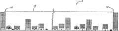
图1表示本发明自由空间光数据传输系统的典型装置正视图,其中由于周围结构和活动的原因可以在该系统的一对收发信机之间产生各种大气条件;Figure 1 shows a front view of a typical installation of the free-space optical data transmission system of the present invention, wherein various atmospheric conditions may arise between a pair of transceivers of the system due to surrounding structures and activities;
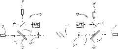
图2表示本发明一个优选实施例的自由空间光数据传输系统中一对望远镜收发信机的示意图,其中每个收发信机配置自适应光学系统以补偿发射和接收光波长中的光像差;2 shows a schematic diagram of a pair of telescope transceivers in a free-space optical data transmission system according to a preferred embodiment of the present invention, wherein each transceiver is configured with an adaptive optics system to compensate optical aberrations in the wavelengths of emitted and received light;
图3表示类似于图2的一对望远镜收发信机的示意图,其中每个收发信机配置改进形式的自适应光学系统;Fig. 3 shows a schematic diagram of a pair of telescope transceivers similar to Fig. 2, wherein each transceiver is equipped with a modified form of the adaptive optics system;
图4表示类似于图2和3的一对望远镜收发信机的示意图,其中仅仅一个收发信机配置自适应光学系统;Figure 4 shows a schematic diagram of a pair of telescope transceivers similar to Figures 2 and 3, wherein only one transceiver is equipped with an adaptive optics system;
图5表示类似于图2,3和4的示意图,其中有多个波前传感器和可变形反射镜的每个收发信机配置自适应光学系统,用于在每个收发信机中完成多种像差补偿;Figure 5 shows a schematic diagram similar to Figures 2, 3 and 4, where each transceiver with multiple wavefront sensors and deformable mirrors is configured with an adaptive optics system for performing various Aberration compensation;
图6表示本发明自由空间光数据传输系统中收发信机的光学系统示意图;Fig. 6 shows the schematic diagram of the optical system of the transceiver in the free space optical data transmission system of the present invention;
图7表示本发明另一个实施例的自由空间光数据传输系统中收发信机的光学系统光路图;Fig. 7 shows the optical system optical path diagram of the transceiver in the free space optical data transmission system of another embodiment of the present invention;
图8表示本发明另一个实施例的自由空间光数据传输系统中收发信机的光学系统示意图;8 shows a schematic diagram of the optical system of the transceiver in the free space optical data transmission system according to another embodiment of the present invention;
图9表示本发明另一个实施例的自由空间光数据传输系统中收发信机的光学系统示意图;9 shows a schematic diagram of the optical system of the transceiver in the free space optical data transmission system according to another embodiment of the present invention;
图10表示本发明自由空间光数据传输系统的收发信机中所用的典型波前传感器的光学系统示意图;Fig. 10 shows the schematic diagram of the optical system of a typical wavefront sensor used in the transceiver of the free space optical data transmission system of the present invention;
图11表示另一个实施例的图9所示波前传感器薄膜反射镜和驱动器的示意图;Fig. 11 represents the schematic diagram of the wavefront sensor film mirror and driver shown in Fig. 9 of another embodiment;
图12表示本发明自由空间光数据传输系统的自适应光学系统中典型可变形反射镜背面上激励器图形的正视图;Fig. 12 shows the front view of the actuator pattern on the back of the typical deformable mirror in the adaptive optics system of the free space optical data transmission system of the present invention;
图13表示类似于图12但具有可变形反射镜的另一种激励器图形的正视图;Figure 13 shows a front view of another actuator pattern similar to Figure 12 but with deformable mirrors;
图14A-14E表示在本发明自由空间光数据传输系统中控制一对收发信机互相对准的操作序列示意图;14A-14E show schematic diagrams of the operation sequence for controlling a pair of transceivers to align with each other in the free space optical data transmission system of the present invention;
图15,16,17和18表示用于分隔和区别本发明自由空间光数据传输系统中每个收发信机发射和接收的数据编码光的不同实施例装置的示意图;Figures 15, 16, 17 and 18 represent schematic diagrams of different embodiment devices for separating and distinguishing data coded light transmitted and received by each transceiver in the free space optical data transmission system of the present invention;
图19表示本发明自由空间光数据传输系统的收发信机中用于发射和接收数据编码光以及分割波前传感器和数据接收器中光的一个简化实施例光纤元件的放大示意图;Fig. 19 shows an enlarged schematic view of a simplified embodiment of an optical fiber element used in the transceiver of the free-space optical data transmission system of the present invention for transmitting and receiving data-encoded light and splitting the light in the wavefront sensor and data receiver;
图20表示利用集成光波导实际分隔发射和接收的数据编码光束的一个实施例放大示意图;Figure 20 shows an enlarged schematic view of an embodiment of using an integrated optical waveguide to actually separate transmitted and received data-encoded light beams;
图21表示数据编码光束的发散阵列特性的示意图,用于说明本发明自由空间光数据传输系统中来自单个望远镜的光束阵列数据传输距离的实际限制。Fig. 21 is a schematic diagram showing the characteristics of a divergent array of data-encoded beams to illustrate the practical limitation of the beam array data transmission distance from a single telescope in the free-space optical data transmission system of the present invention.
具体实施方式Detailed ways
现在参照图1,图1表示城市环境中使用的本发明的自由空间光数据传输系统5,其中该系统的一对收发信机10和10′位于两个隔开很长距离的建筑物屋顶上,但是有没被任何永久性结构阻挡的视线12。收发信机10和10′之一或二者可以安装到建筑物的窗户上以抵御恶劣的气象条件,以及有配置清洁和去除窗口表面水分的装置,从而可以在收发信机10与10′之间沿视线12进行光传输。例如,在窗口表面上安装薄的刮板不会干扰数据的传输和接收。除了气象条件之外,图1中包含不同高度的建筑物,汽车,公路,树木和一个建筑物上烟囱,这些都产生不同的大气条件。雨水,烟雾,等等降低发射光的强度,除了气象条件引起的正常大气像差之外,诸如太阳诱发和结构原因产生的热浪,空调器排放,热交换器排放,汽车尾汽排放等等的条件在沿视线12的方向上产生像差。当然,即使在农村应用本发明自由空间光数据传输系统的情况下,收发信机10与10′之间沿视线12的大气条件也会受到变化的地势,植物和缺乏植物以及气象条件的影响,从而在沿视线12方向上产生变化的像差。本发明的自由空间光数据传输系统减轻这些大气条件,否则它会严重影响数据编码光波的传输和接收。利用本发明收发信机中的自适应光学系统,提供给接收收发信机的数据编码光可以有良好的图像质量。此外,利用双向的光传输,输入光束的波前信息可用于预先校正该发信机中自适应光学系统的发射光束,因为双向光束是在相同的路程上。Referring now to FIG. 1, FIG. 1 shows a free space optical
由于以下说明的各种原因,收发信机10和10′可以有相同或不相同的结构。应当注意,在整个技术说明和附图中,相同的数字和字母用于识别相同或基本相同的元件,而一个收发信机(10′)中带撇(′)的元件用于区别另一个收发信机(10)中相同的元件。
在详细描述本发明的实施例之前,简要地描述一些特征,原理和变化。图1表示收发信机10与10′之间单条自由空间光数据链路,考虑到经济和物理的原因,最好是,光数据链路是双向的,每个收发信机中单个物镜的作用是发射器和接收器的望远镜。然而,如果合适,或连续性或周期性地,一个望远镜可仅仅用作一个发射器,而另一个望远镜可仅仅用作一个接收器;在每个望远镜在名义上不是“收发信机”的单向系统中,即,双向系统,但是为了方便,此处使用的术语“收发信机”表示自由空间光数据传输系统中的双向和单向望远镜装置。即使对于这种单向系统,反向探测光束用于波前传感器的运行,如以下更详细描述的,光是沿两个方向发射,且最好是,探测光束的波长不同于数据编码光束的波长。在本发明系统的每个实施例中,沿相反方向发射的光束暴露到并取样相同的大气条件,因此,每个收发信机检测的波前数据是与数据传输有关。此外,应当注意,可以按照任何方便和常规方式处理或重新发射这个自由空间数据链路中每个收发信机10和10′接收的数据编码光,例如,通过这种类型或其他类型的光纤或另一条自由空间数据链路。Before describing the embodiments of the invention in detail, some features, principles and variations are briefly described. Fig. 1 shows a single free-space optical data link between
在本发明的双向自由空间光数据传输系统中,如下所述,目前最好使用波长为1.55μm(微米)的光,用于数据编码光传输和波前检测,虽然也可以使用不同的波长作数据传输和检测,在某些大气条件下,可以使用其他的波长或许更好。例如,在单个波长下或WDM(波分复用)模式下本系统使用1.33μm波长可以工作得很好,然而,由于若干个大气(OH)吸收特征,在WDM模式下可能出现问题。此外,由于没有合理价格下商品化的1.31μm放大器,这种波长缺乏吸引力。In the two-way free space optical data transmission system of the present invention, as described below, it is currently preferred to use light with a wavelength of 1.55 μm (micrometer) for data encoding optical transmission and wavefront detection, although different wavelengths can also be used for For data transmission and detection, under certain atmospheric conditions, other wavelengths may be used, perhaps better. For example, the system works well with a 1.33 μm wavelength at a single wavelength or in WDM (Wavelength Division Multiplexing) mode, however, problems may arise in WDM mode due to several atmospheric (OH) absorption features. Furthermore, this wavelength is unattractive due to the absence of commercially available 1.31 μm amplifiers at reasonable prices.
虽然使用一对收发信机10和10′通常用在有合理距离的本发明自由空间数据链路,即,1km至2km或更长一些,但在相当远的距离上并列地使用两个或多个自由空间光数据传输系统以增大可靠性也是可行的,而且也是在本发明的范围内,在这种装置中,最好是,收发信机的输出孔径放置成互相接近,且保持发射的数据信号相位。在利用一个或多个相邻孔径的情况下,孔径之间应当足够接近而使接收器望远镜中的图像充分重叠,因此,来自每个望远镜的大部分能量可以耦合到单条光纤。或者,数据链路可以放置成足够远离,使它们之间(在优选实施例中分隔几个弧度分或更大)没有相互作用,因此,它们可以完全独立地运行。在发射器望远镜放置成足够接近的情况下,必须充分注意发射器望远镜的光学相干性,以保证不会遇到因空间相干性或时间相干性而出现的问题。来自每个发射望远镜的数据调制信号应当保持同相。然而,重要的是,每个望远镜的光学相位应当控制到远远小于一个波长,或光学相位的随机化以避免接收器中的干涉效应。可以有源地控制光程长度,但要求第二个波前传感器确定相对的光程长度延迟或发生在不同孔径之间的活塞误差。干涉活塞传感器是本领域中熟知的,它可以基于条纹跟踪或简单的双臂干涉仪。利用相同的激光,分割之后馈入到每个望远镜(可能的相干放大),可以实现光学相位随机化,条件是大于光学相干长度的不同光程延迟引入到每个望远镜中,且这种延迟是与保持足够一致的数据信号相位关系相一致。利用每个望远镜中单独的发射二极管或激光二极管,这意味着利用光-电-光(OEO)转换或非相干光放大器(光晶体管)以转移信号,也可以实现光学相位随机化。类似地,若来自几个独立接收器望远镜的光信号按照光学方式进行组合,则必须十分注意相干性的问题。控制活塞误差或保证信号非相干组合的相同解决方法也可应用于接收器的情况。每当独立光源的光束进行组合时,发射器光源的光带宽必须远远大于数据信号的带宽,以避免多余的时间相干性添加过大的噪声到组合信号中。While the use of a pair of
当前,我们设想,本发明系统发射数据编码光的最理想光源是直接来自光纤。这个光源可以是足够明亮的任何类型激光二极管,并可以在光纤传输速度下进行调制。若数据信号是电信号,则可以进行电光(EO)转换。若数据信号是光信号,但它的波长与本系统的波长不兼容,则可以进行电光(OEO)转换,例如,从1.31μm波长转换成当前自由空间传输系统的1.55μm波长。Currently, we envision that the most ideal source of data-encoded light emitted by the system of the present invention is directly from an optical fiber. This light source can be any type of laser diode that is sufficiently bright and modulated at fiber-optic speeds. If the data signal is an electrical signal, electro-optical (EO) conversion may be performed. If the data signal is an optical signal, but its wavelength is not compatible with the wavelength of the system, an electro-optical (OEO) conversion can be performed, for example, from a 1.31 μm wavelength to a 1.55 μm wavelength for current free-space transmission systems.
两种系统之间传播的光束最小尺寸是由衍射效应设定的。假设投射光束有标准偏差为σ的高斯分布和投射的距离为D,则由于衍射效应引起的投射光束标准偏差为Dλ/πσ,其中λ是传播波长。可以定义特征传播距离,该距离与投射光束的宽度σ有关(约为物镜直径的1/3至1/4)。在等于或大于特征传播距离的情况下,来自投射/发射望远镜的相位信息转换成接收望远镜中的纯幅度变化。特征距离可以定义(有些任意性)为距离Dλ/πσ=σ,即,光束直径扩大成2的平方根倍的距离,则D=πσ2/λ。例如,利用投射σ为4cm的12.5cm直径望远镜透镜,则特征距离约为3km。在特征距离的范围之外,数据信号强度按距离的平方下降。在小于特征距离的范围内,两种系统之间波前相位信息传播增大。在某个距离处,这种相位信息传播造成两个相对自适应光学系统的不稳定性。然而,几何理论指出,在1>>σ的情况下,不稳定性应当不是严重的问题。在距离远远小于特征距离的情况下,发射光纤与接收光纤之间的一些差分焦点可能是需要的,为了保证接收望远镜的孔径不是严重地未充满。此外,在这些较短的距离处,光瞳照明可能因费涅耳衍射变得非均匀,而调整发射光束焦点也可以改进这种情况下的光瞳照明。The minimum size of the beam propagating between the two systems is set by diffraction effects. Assuming that the projected beam has a Gaussian distribution with standard deviation σ and the projected distance is D, the standard deviation of the projected beam due to diffraction effects is Dλ/πσ, where λ is the propagation wavelength. A characteristic propagation distance can be defined, which is related to the width σ of the projected beam (approximately 1/3 to 1/4 of the diameter of the objective lens). At or above the characteristic propagation distance, the phase information from the projecting/transmitting telescope is converted into a pure magnitude change in the receiving telescope. The characteristic distance can be defined (somewhat arbitrarily) as the distance Dλ/πσ=σ, that is, the distance at which the diameter of the beam expands to times the square root of 2, then D=πσ2 /λ. For example, using a 12.5 cm diameter telescope lens with a projection σ of 4 cm, the characteristic distance is about 3 km. Outside the range of the characteristic distance, the data signal strength falls off as the square of the distance. In the range smaller than the characteristic distance, the propagation of wavefront phase information between the two systems increases. At a certain distance, this phase information propagation causes instability of the two opposing adaptive optics systems. However, geometric theory states that in the case of 1>>σ, instability should not be a serious problem. In the case of distances much smaller than the characteristic distance, some differential focal point between the launch and receive fibers may be required in order to ensure that the aperture of the receive telescope is not severely underfilled. Also, at these shorter distances pupil illumination may become non-uniform due to Fresnel diffraction, and adjusting the transmit beam focus can also improve pupil illumination in this case.
现在参照图2-5,四个实施例用于说明收发信机10和10′的典型基本装置和元件,但本领域专业人员应当明白和容易理解,那些代表性系统的各种改动和组合可用于其他具体的应用。图中的每个收发信机10和10′包含反射型望远镜14,14′,但本领域专业人员应当明白和容易理解,可以利用其他类型的望远镜,例如,图6,7和8所示的望远镜。本发明的每个自由空间光数据传输系统5至少包含一个自适应光学系统,作为收发信机10和/或10′中的一部分。虽然有波前传感器的任何形式自适应光学系统可用在数据传输系统5以补偿大气造成光波的像差,其中波前传感器对于光瞳上的光强变化不灵敏,但最好利用这样的系统,该系统有差分,自校准曲率波前传感器和用于改变检测波前的可变曲率反射镜。一些优选波前传感器及其运行的例子是在2000年5月26申请的美国专利申请S.N.09/579,786中描述,其标题为“Method And Apparatus For Wavefront Sensing”,它的发明者与本发明者相同,把它全文合并在此供参考。优选可变曲率反射镜的例子是在2001年1月25日申请的美国专利申请S.N.09/769,988中公开,其标题为“Deformable Curvature Mirror”,它的发明者也与本发明者相同,把它全文合并在此供参考。Referring now to FIGS. 2-5, four embodiments are used to illustrate typical basic arrangements and elements of
更具体地参照图2,图2表示本发明一个优选实施例的自由空间光数据传输系统5,其中每个收发信机10和10′配置自适应光学系统配置。每个自适应光学系统包括:单个波前传感器WFS,WFS′和单个可变形反射镜DM,DM′,分别用于检测和补偿相关望远镜14,14′发射的光波L′,L中的像差。各自波前传感器检测的光波L′,L可以是利用发射数据编码的相同光波或独立的光波,如在以下要更详细讨论的,但为了便于描述,现在我们假设,各自波前传感器接收和检测的光波是与数据编码光波相同的光波。每个收发信机10和10′在双向传输装置中配置任何合适类型的光波发射器T,T′,例如,光纤光波源,和接收器R,R′;发射器用于发射数据编码光到相关的望远镜14,14′,而接收器用于从相关的望远镜接收数据编码光。为了简单明了,首先描述仅沿一个方向的数据传输,即从收发信机10′到收发信机10(图2中从右到左),但是应当明白,也可以沿相反的方向同时发射数据编码光,即,从左到右。在这个实施例中,光L′首先发射通过分束器B-2′和B-1′到中继反射镜RM′,其理由在以下说明,该光被共轭到可变形DM′并回到中继反射镜RM′,然后再到反射镜M′,反射镜M′引导光L′到望远镜14′,望远镜14′发射该光到望远镜14。收发信机10中望远镜14接收的光波L′被转移到反射镜M,光波从反射镜M被引导到中继反射镜RM,中继反射镜RM可以是抛物面形式的反射镜。以下描述反射镜M,M′,可变形反射镜DM,DM′和中继反射镜RM,RM′的具体光学功能及相关内容。然后,入射光波被引导到可变形反射镜DM并从可变形反射镜DM反射回到中继反射镜RM,光波从中继反射镜RM被引导到两个连续放置的分束器B-1和B-2,按照常规的方式,反射到达该分束器的一部分光和透射通过其余部分的光。被第一分束器B-1反射的光波被引导到波前传感器WFS,或直接地或间接地从另一个反射镜M-1到达波前传感器WFS,如图2所示。来自收发信机10′到达波前传感器WFS的初始传输光波L′通常有收发信机10与10′之间大气条件造成的像差,在上述美国专利申请S.N.09/579,786中有充分的描述。接着,波前传感器WFS控制可变形反射镜DM的形状以补偿光波L′的波前像差,于是,波前传感器WFS检测被可变形反射镜DM校正的补偿波前,其中像差被消除或基本消除。因此,传输通过分束器B-1的部分光波L′也被分束器B-2校正,一部分光波L′被分束器B-2反射到收发信机10中光波接收器R,成为与收发信机10′中发射器T′发射的几乎相同形式数据编码光。当大气条件沿视线12(见图1)方向发生变化时,如上所述,这些条件在光波L′中产生新的或不同的像差,这种条件变化被波前传感器WFS检测,再通过改变可变形反射镜DM的形变以补偿变化的像差,从而使光接收器连续接收校正的光波,这是包含波前传感器WFS和可变形反射镜DM的自适应光学系统运行的结果。Referring more particularly to Fig. 2, Fig. 2 shows a free space optical
如在开头和至今所描述的,图2的自由空间光数据传输系统5仅仅沿一个方向(图2中从右向左)发射数据编码光,其中收发信机10的功能是接收和校正收发信机10′发射的光波L′。利用相同或类似的元件提供一个双向数据传输系统,传输系统5还可以沿相反的方向(从左向右)发射和接收数据编码光L。然而,由于波前传感器WFS连续地检测收发信机10接收的光L′波前并通过控制可变形反射镜DM校正这个波前,发射器T发射的光波L也是从可变形反射镜DM上反射,使光波L预先得到校正以补偿收发信机10与10′之间大气条件产生的波前像差。因此,在这对望远镜14,14′发射光波之前,其波前实际上部分地被每个可变形反射镜DM,DM′补偿,然后分别地再被收发信机10′,10中另一个可变形反射镜DM′,DM进行补偿。双向光传输通过视线12上的相同大气,所以,波前传感器WFS,WFS′连续地抽样相同的大气条件和像差。此外,通过发射有其他数据编码光的数据,波前传感器WFS和WFS′可以分享波前补偿的数据。一般地说,与光波源接近的大气条件比较,与接收光波的望远镜接近的大气条件对输入波前相位有较大的影响。另一方面,与发射望远镜接近的大气条件主要影响接收望远镜的幅度和发射光束的方向。发射望远镜附近的像差造成光束的净转向或误导可以使光束不能进入接收望远镜。高级次像差对光束外形产生更复杂的效应,但会类似地调制强度。As described at the beginning and thus far, the free-space optical
为了更有效地补偿大气条件和像差,本发明利用合适的可变形反射镜共轭。可以利用的共轭调整量是受衍射效应的限制。由于实现共轭是在光束路程上重新成像到可变形反射镜DM,DM′上,因此,成像系统(即,望远镜14,14′)在共轭距离上必须充分地分辨可变形反射镜的各自激励器(在图10和11中描述和展示),虽然图像可能有点模糊。最好是,选取这样的光束尺寸,使接收器望远镜是在发射器望远镜的焦散区内,所以,共轭的最大范围约为激励系统链路距离的1/3(见图12)。通过增大望远镜的尺寸,可以扩大共轭的范围,在焦平面上利用发射器/接收器阵列时,这是一个特别诱人的选择,虽然也会使成本增大。在利用多个发射器/接收器源时,使用多共轭自适应光学系统也可以改进校正的视场,可以获得更好的总产量。光学系统必须保持可变形反射镜到波前传感器的准确共轭,并准确地保持薄膜反射镜的中心(以下描述,或与波前参考位置)与输入和输出光纤对齐。To more effectively compensate for atmospheric conditions and aberrations, the present invention utilizes suitable deformable mirror conjugates. The amount of conjugation adjustment that can be utilized is limited by diffraction effects. Since the conjugation is achieved by re-imaging the deformable mirrors DM, DM' on the beam path, the imaging system (i.e., the
现在回到图2实施例中合适共轭的应用,名义上,可变形反射镜DM的可变形反射镜共轭C的位置是在从收发信机10到收发信机10′距离的1/3处,给出像差校正的平均位置;类似地,共轭C′的位置是在从收发信机10′到收发信机10距离的1/3处。然而,若我们确定最大像差一直发生在沿视线12的不同位置上,例如,上述的工厂或大的沥青停车场,则可以利用合适的光学装置,使可变形反射镜共轭C或C′中的一个移动到最大像差的位置,从而最有效地实现波前校正。这样的一种光学装置是在反射镜M位置上的可调变形反射镜,例如,以下参照图12和13所描述的可变形反射镜,但其中仅有单个电极分段激励器。具体地说,通过正确调准反射镜M,可以选取收发信机10中可变形反射镜共轭C的位置,而通过调准反射镜M′,可以选取收发信机10′中可变形反射镜共轭C′的位置,这两个位置通常接近于各自相关的望远镜14,14′和/或最大像差的位置。Returning now to the application of the appropriate conjugate in the embodiment of FIG. 2, the position of the deformable mirror conjugate C of the deformable mirror DM is nominally 1/3 of the distance from
利用自适应光学系统和合适光束尺寸的本发明光数据传输系统5,从可变形反射镜DM,DM′上每个分段反射的光分别填充整个接收望远镜14,14′。Using the inventive optical
现在参照图3,这个实施例的自由空间光数据传输系统5也分别配置有望远镜14和14′的一对收发信机10和10′,如图2所描述的,但每个收发信机中的光波发射,光波接收和自适应光学系统的装置不同于图2实施例中所描述的装置,虽然基本的过程和功能保持不变。此外,收发信机10和10′是相同的,且每个收发信机配置发射器T,T′,接收器R,R′以及有波前传感器WFS,WFS′和可变形反射镜DM,DM′的自适应光学系统。数据编码光是由每个发射器T,T′发射,并从第一分束器B-1,B-1′直接反射到望远镜14和14′,用于发射光波L,L′到另一个望远镜,其中没有图2所示首先被可变形反射镜反射。每个望远镜14,14′接收的光波传输通过第一分束器B-1,B-1′到达反射镜M,M′,其中光线被反射到中继反射镜RM,RM ′,然后到达可变形反射镜DM,DM′,回到中继反射镜RM,RM′,再到达第二分束器B-2,B-2′,其中一部分光传输通过分束器到达接收器R,R′,而其余部分光直接地或间接地从反射镜M-1,M-1′反射到波前传感器WFS,WFS′。在这个实施例中,仅仅输入光波被那个收发信机10和10′中的自适应光学系统校正,因为来自每个发射器T,T′的发射光波被第一分束器B-1,B-1′直接反射到相关的望远镜14,14′,而不是预先被校正,如同图2实施例的收发信机10和10′中来自每个发射器T,T′的光波那样。图3的这个实施例在每个收发信机中具有自适应光学系统的优点,可以独立和分开地校正输入光波的波前,它简化了系统但不能有助于校正输出光波。如果需要,每个收发信机中发射器T,T′和接收器R,R′的位置可以倒置,因此,基于相关波前传感器WFS,WFS′接收的光L′,L,发射的光在发射之前被可变形反射镜DM,DM′校正。Referring now to FIG. 3 , the free space optical
现在参照图4,自由空间光数据传输系统5在右侧收发信机10中仅有单个自适应光学系统(波前传感器WFS和可变形反射镜DM),虽然它与图2所示收发信机10中配置的自适应光学系统相同或基本相同。虽然图4的这个实施例可用于双向数据传输,但它不如图2和3实施例那样适合于双向数据传输,而是更适合于单向数据传输,例如,从地面的收发信机10到卫星上的收发信机10′。收发信机10′有用于发射探测光束L′的发射器T′,最好是,光束L′的波长不同于数据编码光L的波长,以便容易区别这两种光束。通过控制可变形反射镜DM以便提前校正发射器T通过望远镜14发射到望远镜14′的数据编码光L,其中数据编码光L被接收器R′接收,波前传感器WFS响应于光束L′以补偿像差。在这个装置中,接收器R′可以是用于检测光强的简单光纤。此外,最好是,收发信机10中反射镜M是可共轭的,用于建立可变形反射镜共轭C的最理想位置。若图4中数据传输系统5用在地球上收发信机10与卫星上收发信机10′之间,则所有的像差发生在接近于地面上收发信机10的大气中,所以,共轭C的位置接近于收发信机10。Referring now to FIG. 4, the free-space optical
现在参照图5,图5表示另一个实施例的本发明自由空间光数据传输系统5,它代表该系统可以包含的复杂性和精密改进。图5的实施例类似于图2的实施例,其中每个收发信机10,10′在用于校正发射光波和接收光波的自适应系统的位置上有发射器T,T′和接收器R,R′。现在,每个收发信机10,10′中的自适应系统配置多个波前传感器WFS(例如,6个波前传感器,WFS-1至WFS-6和WFS-1′至WFS-6′)和多个可变形反射镜DM(例如,5个可变形反射镜,DM-1至DM-5和DM-1′至DM-5′),在具体应用数据传输系统5时可以有任何合适的数目。由于实施方面存在的问题,每个收发信机中波前传感器的数目通常不应当少于控制可变形反射镜的可变形反射镜数目,波前传感器数目可以多于可变形反射镜数目,如图所示,可以增加波前检测和数据整形。每个可变形反射镜是与该收发信机中的波前传感器匹配,例如,可变形反射镜DM-1是与收发信机10中的波前传感器WFS-1匹配,相继地,可变形反射镜DM是与它们接收光波相同顺序的波前传感器WFS匹配,即,从右至左的可变形反射镜DM-1至DM-5是与图5所示收发信机10中从上至下的波前传感器WFS-1至WFS-5匹配。第六个波前传感器WFS-6,WFS-6′与一个或多个其他波前传感器分享数据。共轭可调反射镜M分别给可变形反射镜DM-1至DM-5建立可变形反射镜共轭C-1至C-5,而共轭反射镜M′给收发信机10′中可变形反射镜DM-1′至DM-5′建立共轭关系。每个收发信机中多个可变形反射镜DM互相之间可以有不同的距离,把它们放置在与共轭反射镜M,M′之间的不同距离处,可以改变共轭之间的间隔。例如,若前两个可变形反射镜DM-1与DM-2之间的间隔是每对其余可变形反射镜DM-2至DM-5之间间隔的两倍,则前两个共轭C-1与C-2之间间隔是相继共轭C-2与C-5之间间隔的两倍。此外,为了简单明了,虽然在图5中说明收发信机10中共轭C-1至C-5是在收发信机10′中共轭C-1′至C-5′的左侧,但本领域专业人员应当明白和理解,每个收发信机的共轭可以另一个收发信机的共轭重叠。此外,虽然每个可变形反射镜名义上是与特定的波前传感器匹配,但本领域专业人员应当明白和理解,来自每个波前传感器的波前数据可以与相同或不同收发信机中的其他波前传感器分享波前数据,为了可以优化波前校正。仅仅一部分的总波前校正是由每个可变形反射镜完成的。可变形反射镜可以配置不同数目和图形的电极激励器(见图12和13以及下面的描述)以改进像差补偿,但一般地说,与收发信机距离较近共轭的可变形反射镜可以配置较多的电极激励器以获得更精确的控制,在该收发信机中安装了可变形反射镜。此外,应当注意,图5中的中继反射镜RM,RM′各自有两个分开的元件,若要求不同的可变形反射镜装置,则中继反射镜RM,RM可以包含附加的元件。Referring now to FIG. 5, there is shown another embodiment of the free space optical
图6表示典型的收发信机10a的示意图,其中比图2-5更详细地涉及瞄准自适应光学系统OA的望远镜。望远镜14a表示成从翻倒-倾斜(tip-tilt)反射镜16(它可以是相同或添加到上述反射镜M,M′)接收光波L的透镜,反射镜16沿本发明自由空间光数据传输系统的视线12从发射器Ta接收光。在这个实施例中,试图把望远镜放置在沿垂直方向(尽管为了便于说明采用图6中的方向),它与图1-5中的不同,而翻倒-倾斜反射镜16能够绕两个垂直轴旋转,一个轴是在望远镜的垂直轴上,像个转塔,另一个轴是在反射镜平面的水平方向,造成“翻倒”和“倾斜”调整,可以瞄准直接沿视线12的反射镜。或者,望远镜14a可以绕与垂直轴相同的轴旋转,或作为单独单元,或与整个收发信机10a一起,大致沿视线12的方向瞄准反射镜16,从而可以去掉反射镜16转动的车轴。可以利用指向或瞄准望远镜过程的另一种装置,例如,利用其他的翻倒-倾斜反射镜或可变形反射镜或少许平移物镜。利用翻倒-倾斜反射镜16和/或绕其自身轴转动的望远镜和/或其他装置,收发信机10a可以准确地沿视线12对准这个数据传输系统中的其他收发信机,而不要求整个收发信机10a沿所有三个垂直轴的调整运动。来自望远镜14a的光波聚焦到可变形反射镜共轭调准元件18,该元件可以如图所示和可以包含参照图2-5描述的单个元件可变形反射镜M,M′。然后,光线传输通过AO中继20到达可变形反射镜DMa,其中AO中继20可以对应于图2-5所示的中继反射镜RM,RM′,而可变形反射镜DMa最好是上述美国专利申请序列号No.09/769,988中公开的可变曲率类型反射镜。光从可变形反射镜DMa反射到透镜22,透镜22重新聚焦图像到图像检测器D的平面,而图像检测器D可以对应于上述的接收器R,R′。图像检测器D可以是任何方便的类型,它适合于本发明自由空间光数据传输系统的特定应用,例如,传输数据编码光的光纤或使用光的任何其他合适检测器,例如,摄像机,定制格式的电荷耦合器件,单个PIN二极管,PIN二极管阵列,光子计数检测器,等等。然后,光或数据可以传输到作其他用途的任何合适器件24。当可变形反射镜DMa没有激活并工作在与波前传感器的闭环时,如以下所描述的,图像检测器D接收的图像或光波前是望远镜14a接收的非校正图像。当可变形反射镜DMa正确地发生形变以补偿像差时,图像检测器D接收的图像是衍射受限的,即,光波L中像差校正的波前发射到收发信机10a。相反,当收发信机10a用于发射数据编码光线时,发射装置,例如,检测器D位置上放置的光纤,就发射光到可变形反射镜DMa并通过望远镜14a到达另一个收发信机,如参照图2-5所描述的。在收发信机10a中,波前传感器WFS借助于分束器B接收一部分指向检测器D的光,该光是校正或非校正取决于可变形反射镜是否被激活,该数据传输到中央处理单元CPU由数据简约软件进行处理,从而推导出该优选实施例中的波前曲率,并提供适合于可变形反射镜DMa运行的数据。具体地说,本领域专业人员都知道,通过求解泊松方程导出或恢复的波前是在Dirichlet边界条件下的强度,它相对于该选实施例中波前传感器WFS检测的焦外图像形状,如在上述美国专利申请序列号No.09/579,786和09/769,988中所描述的。然后,通过多条导线W-1,W-2,W-3至W-N,CPU提供多个单独和受控的高压电势到可变形反射镜DMa背面上的多个单独的导电电极分段(以下参照图12和13所描述的)。可变形反射镜DMa固定地安装到支架25上,通过加高电压到选取的电极分段,可以改变该反射镜的总斜率,即,光轴O的反射角;而可以改变可变形反射镜DMa的表面曲率,其中通过其他导线加受控高压到其他电极分段来校正像差,从而可以校正波前曲率并由波前传感器WFS检测。Fig. 6 shows a schematic diagram of a
图7表示利用略微不同光学装置的另一个实施例收发信机10b。收发信机10b也配置完成相同功能的翻倒-倾斜反射镜16和望远镜14b,但是该望远镜直接转移光波到可变形反射镜DMb,光线从可变形反射镜DMb反射到分束器B,从而使光波在检测器D(或反射器R)与波前传感器WFS之间进行分配。Figure 7 shows another embodiment transceiver 10b utilizing slightly different optics. Transceiver 10b is also configured with tilt-
图8表示有不同望远镜和自适应光学装置的另一个实施例收发信机10c,该装置也利用可控翻倒-倾斜反射镜16以引导光线到主反射镜28,主反射镜28反射光线到透镜30,透镜30引导光线到可变形反射镜DMc。然后,光线被引导到分束器B,从而使光线在检测器D与波前传感器WFS之间进行分配。这个望远镜实施例类似于盒式磁带型,不同的是次反射镜是由两个光学元件构成,而不是一个简单的凸面反射镜。利用刚好在可变形反射镜DMc之前二次通过的折射元件,可变形反射镜DMc可以是十分简单的平面反射镜,而不是曲面反射镜。Figure 8 shows another embodiment transceiver 10c with a different telescope and adaptive optics arrangement, which also utilizes a controllable tip-
图9表示有不同望远镜和自适应光学装置的另一个实施例收发信机10d。翻倒-倾斜反射镜16引导光线到抛物面反射镜29,抛物面反射镜29反射和引导光线到可变形反射镜DMd,可变形反射镜DMd再反射光线到分束器,从而使光线在检测器D与波前传感器WFS之间进行分配。这种离轴反射型望远镜在某些应用中有优越性。Figure 9 shows another
如上所述,在图6,7,8和9所示四个望远镜/AO系统的每个系统中,在检测器D的位置上可以配置图2-5中公开的系统5的接收器R或发射器T,或者如这些附图所示,可以配置一个或多个附加分束器以适应附加的接收器和/或发射器。此外,波前传感器WFS中必要检测器(未画出)的位置也可以是检测器D,接收器R和/或发射器T的相同位置。As mentioned above, in each of the four telescope/AO systems shown in Figs. 6, 7, 8 and 9, at the position of detector D, receiver R or The transmitter T, or as shown in these figures, may be configured with one or more additional beam splitters to accommodate additional receivers and/or transmitters. Furthermore, the positions of the necessary detectors (not shown) in the wavefront sensor WFS can also be the same positions of the detector D, the receiver R and/or the transmitter T.
作为说明而不是限制性,图10表示可以在上述本发明实施例中使用的典型波前传感器WFS。来自分束器B的光线聚焦到支架34上固定的薄膜反射镜32,支架34连接到可调空腔装置36,可调空腔装置36连接到声驱动器38,它以高的振动速率声驱动薄膜反射镜32,例如,4.0kHz,但不限于4.0kHz。可以想象高达25kHz或更高的速率振动反射镜32可能是有利的。从薄膜反射镜32反射的光线传输通过准直透镜40到达波前传感检测器42。当薄膜反射镜32没有激励到振动状态时,即,当薄膜反射镜32是平坦时,可变形反射镜的图像光学聚焦到检测器42。然而,当薄膜反射镜32振动时,它在凹面与凸面状态之间弯曲,从而使检测器42上的图像是正或负交替地散焦,把该数据传输到CPU(见图6),就可以按照上述方式确定光波前的曲率。By way of illustration and not limitation, Figure 10 shows a typical wavefront sensor WFS that may be used in embodiments of the invention described above. The light from the beam splitter B is focused onto a thin film mirror 32 fixed on a support 34, which is connected to an adjustable cavity device 36, which is connected to an acoustic driver 38, which is acoustically driven at a high vibration rate Thin film mirror 32, for example, 4.0 kHz, but not limited to 4.0 kHz. It is conceivable that vibrating the mirror 32 at a rate of up to 25 kHz or higher may be advantageous. Light reflected from the pellicle mirror 32 travels through a collimating lens 40 to a wavefront sensing detector 42 . When the pellicle mirror 32 is not actuated into a vibratory state, ie, when the pellicle mirror 32 is flat, the image of the deformable mirror is optically focused onto the detector 42 . However, when the pellicle mirror 32 vibrates, it bends between the concave and convex states so that the image on the detector 42 is defocused alternately positive or negative, and this data is transmitted to the CPU (see FIG. 6 ), which can The curvature of the light wavefront is determined as described above.
图11表示利用静电力的另一种结构振动薄膜反射镜32。具体地说,薄膜反射镜44有导电反射层,它电路上连接到能够输出正和负电压的驱动放大器45。另一个放大器46产生的固定电压加到薄膜反射镜44附近安装的稳定电极47上。当反射镜44和电极47有相同的电荷时,薄膜就偏离电极47,如图中虚线44a所示;而当薄膜反射镜44和电极47有相反的电荷时,薄膜就偏向电极47,如图中虚线44b所示。通过调整放大器45,振动的幅度和频率可以调整到与AO系统的能见度条件匹配。振动反射镜32和44对AO系统的运行提供一对散焦图像。由于这对散焦图像是以这样快的频率出现的,例如,4.0kHz,波前传感器对可变形反射镜的控制几乎是瞬时(与喘流进展时间比较),连续和实时进行的,用于校正本发明收发信机接收或发射的数据编码光波前。虽然还可以利用其他的波前传感器,美国专利申请序列号No.09/579,786中公开了其他形式的波前曲率传感器。Fig. 11 shows another structure vibrating thin film mirror 32 using electrostatic force. Specifically, a
图12和13表示可用于可变曲率反射镜DM,DM′背面上的典型电极分段图形,这种反射镜最好用在本发明的自由空间光数据传输系统中。如在上述美国专利申请序列号No.09/769,988中已充分描述的,可变形反射镜DM最好是由任何限制电流材料的两个圆盘或平板(未画出)构成,例如,PZT或PMN,这些材料与反射镜一起叠层形成在一侧,而在另一侧形成电极分段图形。图12和13表示两个典型的这种图形。如图12所示,可以提供12个电极分段50的外环,6个电极分段52的内环和单个中央电极分段54,以形成19个独立的电极分段,在这些电极分段上可以分别加高电压电势并进行控制,从而控制可变形反射镜DM的形变。通过有选择地加电压到这12个分段上,电极分段50的外环可用于控制反射镜的倾斜。电极分段52的内环和中央分段54用于控制某个区域的反射镜形变,这个区域是引导数据编码光入射的区域,用于校正光波前的曲率。以上参照图6描述的导线W-1,W-2,W-3至W-N分别连接到电极分段50,52和54,可以加控制电压到这些电极分段中的每个分段。6个导电分段56的中环分别形成在电极分段50的外环与电极分段52的内环之间,而这些中间分段56是电路接地的,以避免静电电荷建立在那部分的可变形反射镜上,否则可能造成PZT或PMN的多余膨胀/收缩以及可变形反射镜DM的运动/形变。Figures 12 and 13 show typical electrode segment patterns that can be used on the back of variable curvature mirrors DM, DM', which are preferably used in the free-space optical data transmission system of the present invention. As fully described in the aforementioned U.S. Patent Application Serial No. 09/769,988, the deformable mirror DM is preferably constructed of two disks or plates (not shown) of any current-limiting material, such as PZT or PMN, these materials are laminated with mirrors on one side and electrode segments patterned on the other side. Figures 12 and 13 show two typical such patterns. As shown in Figure 12, an outer ring of 12 electrode segments 50, an inner ring of six electrode segments 52 and a single central electrode segment 54 may be provided to form 19 separate electrode segments, in which electrode segments High voltage potentials can be respectively applied and controlled, thereby controlling the deformation of the deformable mirror DM. By selectively applying voltage to these 12 segments, the outer ring of electrode segments 50 can be used to control the tilt of the mirror. The inner ring of the electrode segment 52 and the central segment 54 are used to control the deformation of the mirror in a region that guides the incident data-encoded light and is used to correct the curvature of the light wavefront. The wires W-1, W-2, W-3 to W-N described above with reference to FIG. 6 are connected to the electrode segments 50, 52 and 54, respectively, and a control voltage can be applied to each of these electrode segments. The middle rings of the six conductive segments 56 are respectively formed between the outer ring of the electrode segment 50 and the inner ring of the electrode segment 52, and these middle segments 56 are circuit grounded, so as to prevent static charges from being built up in that part. Deformable mirror, otherwise it may cause unnecessary expansion/contraction of PZT or PMN and movement/deformation of deformable mirror DM.
类似地,图13中可变形反射镜M′的电极图形包括:16个分段50′的外环,一对12个分段51和6个分段52′的同心内环,和单个中央电极分段54′,以形成35个电极分段,在电极分段上可以分别加高电压并进行控制,使可变形反射镜DM发生形变。此外,分段50′外环和中央分段51,52′和54′内环的作用是使控制波前曲率的反射镜发生形变。导电分段56′的中环是接地的,如同图12中的图形。本领域专业人员应当明白和理解,可以提供多于或少于图12和13中电极分段和接地分段的数目,并且还可以改变分段的形状和取向。Similarly, the electrode pattern of the deformable mirror M' in Figure 13 includes: an outer ring of 16 segments 50', a pair of concentric inner rings of 12
现在参照图14A-14E,这些图表示本发明自由空间光数据传输系统中两个收发信机10与10′之间建立通信链路的过程示意图。当这种类型光通信链路最初开始时,或通信链路由于短暂的阻塞或环境条件而中断时,例如,浓雾,地震,暴风雨,有收发信机的高楼在强风中摇晃,等等,必须通过两个收发信机10,10′互相准确地瞄准而建立通信链路,最好是,每当收发信机在工作而不能互相接收光波时,应当自动地完成瞄准过程。按照本发明,由于每个收发信机中的波前传感器WFS具有检测光信号的能力,即使在相当弱的照明条件下,只要所需的带宽很小,可以完成这种自动瞄准和对齐。图14A表示两个收发信机10,10′在在没有对齐的状况,即,各自的光束L和L′偏离两个收发信机之间的视线12(见图1)。若检测到这种状况,例如,虽然两个收发信机正在发射光,而每个收发信机不能接收到任何的光,则一个收发信机10′的工作是散焦它的输出光束,例如,对可变形反射镜的控制加上合适的偏置,从而使一些发射光L′入射到另一个收发信机10上,如图14B所示。或者,两个收发信机10,10′可以同时散焦输出光束,但为了便于解释,以下描述的方法仅仅使一个光束散焦。此外,应当注意,收发信机中的每个波前传感器具有适当的采集视场F/V(图14中虚线所示的收发信机10),用于从散焦光束实际地接收光。采集视场F/V是波前传感器结构的函数,例如,对于图10所示的波前传感器,采集视场是由薄膜反射镜32的尺寸(直径)所确定。现在,对于1至2km的数据传输系统5,我们预期,采集视场尺寸约为2弧度分是合适的。每个发射器最好配置功率驱动机构,用于准确地改变收发信机瞄准的方向,例如,参照图6所描述的翻倒-倾斜反射镜16,或望远镜可以安装到万向支架上并瞄准,如图14A-14E所示。响应于散焦光束L′在收发信机10中诱发的微弱波前传感器信号,如图14B所示,收发信机10缓慢地调整对收发信机10′的瞄准点,如图14C所示。由于收发信机10中望远镜孔径处的低照明强度,这种调整的带宽是很窄的。对于因闪烁造成变化的孔径照明取平均,窄的带宽也有助于系统的重新锁定。在收发信机10准确指向收发信机10′的情况下,如图14C所示,收发信机10′检测到照明强度的增大,对此的响应是,在窄带宽下接通它的自适应光学环路,和开始消除光束L′的散焦,如图14D所示,并开始瞄准收发信机10。随着波前传感器照明强度在这个瞄准过程期间的增大,两个收发信机系统接增大自适应光学系统校正的带宽,直至收发信机10,10′互相准确地瞄准,如图14E所示。一旦数据传输系统对齐,在运行期间不再要求重新对准,除非发生了破坏性状况,例如,大雾或实际物体使光束受阻,如被直升飞机阻塞,极其恶劣的条件造成光束中断,例如,大风,暴风雨,地震等,或部分元件失效。在任何的情况下,本发明的数据传输系统此后会按照图14A-14E所示的上述方式自动地重新调整自身的运行。Referring now to FIGS. 14A-14E , these figures show schematic diagrams of the process of establishing a communication link between two
在自由空间光数据传输系统的大部分应用中,例如,本发明的系统,从经济观点考虑,要求数据传输是双向进行,如图2-5中所描述的,虽然分别沿相反方向发射数据编码光的单独系统也是可行的。在双向数据传输系统中,每个收发信机中的发射信号和接收信号必须是可区别(可分隔)的,以避免发射的数据编码光与接收的数据编码光之间发生混合,例如,因浓雾产生反向散射而发生的混合。本发明设想利用至少五种不同物理方法中的一个或多个,用于区别/分隔通信链路中每个收发信机的输入光束和输出光束,这五种方法大致可以按照以下进行分类:In most applications of free-space optical data transmission systems, such as the system of the present invention, from an economic point of view, data transmission is required to be bidirectional, as described in Figures 2-5, although the data codes are transmitted in opposite directions respectively A separate system of light is also feasible. In a two-way data transmission system, the transmit and receive signals in each transceiver must be distinguishable (separable) to avoid mixing between transmitted data-encoded light and received data-encoded light, e.g. because Mixing occurs when dense fog produces backscattering. The present invention contemplates the use of one or more of at least five different physical methods for differentiating/separating the input and output beams of each transceiver in a communication link, which can be broadly categorized as follows:
(1)利用波长分割;(1) using wavelength division;
(2)利用正交的线性偏振光或右旋和左旋圆偏振光;(2) Utilize orthogonal linearly polarized light or right-handed and left-handed circularly polarized light;
(3)利用时域复用;(3) Using time domain multiplexing;
(4)利用光传播方向;和(4) using the light propagation direction; and
(5)利用空间分集。(5) Utilize space diversity.
以下参照图15-18中所示的具体实施例更详细地描述这五种方法中的一些方法,首先,在公开的内容中简要地总结这些方法中的每种方法是合适的。利用波长分割的第一种方法涉及利用两个收发信机发射的两种不同波长的光,其中利用与每个收发信机中接收器相关的合适分量以鉴别发射光波长和接收光波长。利用线偏振光或圆偏振光的第二种方法包括利用偏振器和收发信机,有区别地起偏每个收发信机发射的光,使被接收的偏振光可以区别于该收发信机发射的光。利用时域复用的第三种方法包括利用每个收发信机中的元件,可以间隙地发射和接收光波,即,在短的时间周期内,当一个收发信机发射光波时,另一个收发信机仅仅接收光波,反之亦然。利用光传播方向的第四种方法设想利用常规的光纤环路器以分隔沿相反方向传输的光束,其中利用内偏振和法拉第转子以分隔相反方向传播的光束,虽然这种方法有潜在的问题,它不能分隔反向散射的发射光和从另一个收发信机接收的光。利用空间分集的第五种方法设想实际分隔每个收发信机的望远镜内发射光束和接收光束,例如,发射器偏离系统光轴的方向和/或距离不同于接收器偏离系统光轴的方向和/或距离,它使发射光的增强反向散射不能射入相同收发信机中的接收器。现在参照图15-18描述这种方法中一些方法的具体例子。Some of these five approaches are described in more detail below with reference to the specific examples shown in Figures 15-18, first of all it is appropriate to briefly summarize each of these approaches in the disclosure. A first method using wavelength division involves using two different wavelengths of light transmitted by two transceivers, using the appropriate components associated with the receivers in each transceiver to identify the transmitted and received light wavelengths. The second method of using linearly or circularly polarized light involves using polarizers and transceivers to differentially polarize the light emitted by each transceiver so that the received polarized light can be differentiated from that emitted by that transceiver. of light. A third method using time-domain multiplexing involves utilizing elements in each transceiver that can transmit and receive light waves intermittently, that is, for short periods of time while one transceiver transmits light waves, the other transmits and receives light waves. Transceivers only receive light waves, and vice versa. A fourth approach using the direction of light propagation envisages the use of conventional fiber optic circulators to separate beams traveling in opposite directions, using internal polarization and a Faraday rotator to separate beams traveling in opposite directions, although this approach has potential problems, It cannot separate backscattered transmitted light from light received from another transceiver. A fifth approach to exploit space diversity envisions physically separating the transmit and receive beams within each transceiver's telescope, e.g., the direction and/or distance of the transmitter from the optical axis of the system is different than the direction and/or distance of the receiver from the optical axis of the system and and/or the distance that prevents the enhanced backscatter of transmitted light from reaching a receiver in the same transceiver. Specific examples of some of these methods are now described with reference to FIGS. 15-18.
图15表示利用偏振片和1/4波片以区别/分隔输入光束和输出光束的方法示意图。每个收发信机10,10′配置发射器T,T′,接收器R,R′,波前传感器WFS,WFS′和在接收器与波前传感器之间传播光波的分束器B,B′,其方式与上述的收发信机类似或完全相同。此外,收发信机10,10′在沿数据编码光的传输光轴上包含偏振光分束器PB,PB′和1/4波片QP,QP′。第一收发信机10中发射器T发射的光L(点划线所示)传输通过偏振光分束器PB,分束器PB可以透射一种状态偏振光和反射另一种状态偏振光而离开光学系统,从而分隔相反的偏振态。然后,光L传输通过1/4波片QP,1/4波片QP把线偏振态转变成圆偏振态,使光L传播到另一个收发信机10′中的望远镜,其中光L传输通过另一个1/4波片QP′,1/4波片QP′把光L转变成它的线偏振光,其偏振方向相对于偏振光分束器PB的原始偏振方向成90°。然后,光L从偏振光分束器PB′反射到分束器B′,其中一部分偏振光从分束器B′反射到波前传感器WFS′,而其余部分偏振光传输通过分束器B′到接收器R′。类似地,第二收发信机10′中发射器T′发射光L′(虚线所示)通过偏振光分束器PB′,1/4波片QP′和1/4波片QP,因此,其偏振方向相对于偏振光分束器PB′的原始偏振方向成90°,所以,光L′从偏振光分束器PB反射到分束器B,其中一部分光反射到波前传感器WFS,而其余部分光传输通过分束器B到收发信机10中的接收器R。因此,可以看出,在每个收发信机10,10′中的偏振光分束器PB,PB′与1/4波片QP,QP′之间,光被起偏成两个垂直方向,即,接收偏振光和发射偏振光的方向偏移90°,从而实现数据编码光的完全区别/分隔。FIG. 15 shows a schematic diagram of a method for distinguishing/separating the input beam and the output beam by using a polarizer and a 1/4 wave plate. Each
图16表示类似于图15所示的光束区别/分隔装置,所以,相同的元件有相同的标记,我们仅描述这两种系统之间的差别。在这个实施例中,每个收发信机10,10′配置1/2波片HP,HP′(而不是图15所示的1/4波片QP,QP′),每个1/2波片使偏振光L,L′旋转任何所需的量,用于区别/分隔输出光束和输入光束,如果需要,抑制增强的反向散射。由于与1/2波片HP,HP′造成的不同偏振方向,第一收发信机10在如图15所示相同位置有它的元件,但第二收发信机10′在不同位置有它的元件。具体地说,第二收发信机10′中发射器T′是指向偏振光分束器PB′的表面,其中偏振光L是从该表面反射并通过1/2波片HP′和1/2波片HP到达偏振光分束器PB,偏振光分束器PB反射光L′到收发信机10中的波前传感器WFS和接收器R。相反地,来自收发信机10中发射器T的光L传输通过偏振光分束器PB,1/2波片HP,另一个1/2波片HP′和偏振光分束器PB′到分束器B,其中一部分光L反射到波前传感器WFS′,而其余部分光传输通过分束器B′到达接收器R′。在每次传输过程中,通过调整1/2波片HP,HP′而使偏振方向仅仅旋转22.5°,可以在两个收发信机中保持对称性。同样地,可以实现光束L,L′的完全区别/分隔,使收发信机发射的光不能反射回到它的接收器。Figure 16 shows a beam differentiation/separation arrangement similar to that shown in Figure 15, so like elements are given like numbers and we describe only the differences between the two systems. In this embodiment, each
图17表示用于区别/分隔各自收发信机10和10′中输入和输出光束的另一个实施例,其中利用来自两个不同收发信机10,10′中两个不同波长的发射光束。现在,收发信机10,10′各自配置发射光和接收光传输通过的光纤波分复用器(WDM)或光纤环路器60,60′。来自第一收发信机10中发射器T的光L传输通过波分复用器或环路器60,然后通过分束器B到达第二收发信机10′中分束器B′,其中一部分光L反射到波前传感器WFS′,而其余部分光传输通过分束器B′到达WDM或环路器60′,WDM或环路器60′分隔给定波长的光L和其他波长的光,并发射该光L到第二收发信机10′中的接收器R′。类似地,第二收发信机10′中发射器T′发射的波长不同于光L的光L′通过WDM或环路器60′,再通过分束器B′到达另一个收发信机10中分束器B,其中一部分光L′反射到波前传感器WFS,而其余部分光传输通过分束器B到达WDM或环路器60,WDM或环路器60仅把该波长的光L′传输到接收器R。虽然可以利用任何数目的不同波长以完成这个实施例中的区别/分隔功能,但最好是,使用1550nm“C”波段中的两个波长,当然也可以使用1310nm和1550nm波长的光。Figure 17 shows another embodiment for distinguishing/separating the input and output beams in the
图18表示用于区别/分隔收发信机发射和接收的数据编码光的另一个实施例,这个实施例利用以上简要描述的空间分隔方法。同样地,每个收发信机10,10′包含望远镜14,14′和波前传感器WFS,WFS′。关于这个实施例中波前传感器WFS,WFS′和相关的可变形反射镜(未画出)的运行,可以利用单独的参考光源LS,LS′,以下描述这种参考光源,即使可以利用以上实施例中描述的数据编码光。来自光源LS的参考光(实线所示)从偏振光分束器PB反射到分色分束器DB,然后,通过望远镜14到达第二收发信机10′中的望远镜14′,其中参考光从第二分色分束器DB′反射到第二偏振光分束器PB′,使偏振参考光反射到波前传感器WFS′,用于运行收发信机10′中的自适应光学系统。类似地,第二收发信机10′中的参考光源LS′(也是相同的实线)发射参考光通过偏振光分束器PB′,它从分色分束器DB′反射通过望远镜14,14′到达分色分束器DB,其中它反射通过偏振光分束器PB到达波前传感器WFS,用于运行收发信机10中的自适应光学系统。利用光源LS,LS′提供的参考光束中偏振光可以消除进入波前传感器WFS,WFS′的反向散射光,而利用波长不同于数据编码光的参考光LS,LS′可以提供它们之间的区别/分隔功能。每个收发信机10,10′配置用于发射和接收数据编码光的匹配光纤阵列FA,FA′。例如,在不限制本发明范围的条件下,图18说明每个光纤阵列FA,FA′中的16条光纤,而每个光纤阵列FA,FA′中的下半部分(两行各4条光纤)包含发射数据编码光的光纤,而上半部分(两行各4条光纤)提供从其他收发信机接收光线的接收器。具体地说,第一收发信机10的光纤发射器FT发射光L(长划和短划线)通过分色分束器DB,两个望远镜14,14′和另一个分色分束器DB′到达第二收发信机10′中的匹配光纤接收器FR′。类似地,第二收发信机10′的光纤发射器FT′发射光L′(虚线)通过分色分束器和望远镜到达对应位置的另一个收发信机10的光纤接收器FR。每个光纤阵列FA,FA′中的其余光纤是同样匹配的,使光学系统分别引导来自一个光纤发射器FT,FT′的光仅到达一个光纤接收器FR′,FR。因此,在每个收发信机中发射光束和接收光束是在不同的位置而它们实际上分开,从而可以实现双向的数据传输。Figure 18 shows another embodiment for distinguishing/separating data encoded light transmitted and received by a transceiver, this embodiment utilizing the spatial separation method briefly described above. Likewise, each
图19表示是光纤实施例中高度放大的视图,它可用于本发明的自由空间光数据传输系统,以分享接收器与波前传感器之间的数据编码光束,而不是利用分束器分隔光束。光纤末端抛光成与轴之间有很小的夹角,并涂敷成为分束器,因此,入射到光纤末端任何部分的光反射到波前传感器以提供实现该功能的光。光纤末端上的涂层对于波长分割可以是中性或分色性。当光入射到光纤芯的中心部分时,该光被分色分束器或中性涂层进行光谱分割,从而在双向数据传输装置中完成区别/分隔输入和输出光束的功能。Figure 19 shows a highly magnified view of an embodiment of an optical fiber that can be used in the free-space optical data transmission system of the present invention to share the data-encoded beam between the receiver and the wavefront sensor instead of splitting the beam with a beam splitter. The fiber end is polished to a small angle to the axis and is coated to act as a beam splitter so that light incident on any part of the fiber end is reflected to the wavefront sensor to provide light for this function. The coating on the fiber end can be neutral or dichroic for wavelength splitting. When light is incident on the central part of the fiber core, the light is spectrally split by a dichroic beam splitter or a neutral coating, thereby completing the function of distinguishing/separating input and output beams in a bidirectional data transmission device.
图20表示在双向数据传输系统中物理分隔发射光束和接收光束的另一种装置。通过沉积介质材料的图形到基片上以形成所需的光波导图形,或者,小的充空气通道72和74可以形成在波导70中并涂敷合适的金属或介质反射层,可以制成集成光波导70。最好是,物理阻挡层76形成在两个空气通道72与74之间的波导中。光可以从通道72中的光纤FT发射,而接收的光可以被通道74中的光纤FR接收。Figure 20 shows another arrangement for physically separating the transmit and receive beams in a bi-directional data transmission system. By depositing a pattern of dielectric material onto a substrate to form the desired optical waveguide pattern, alternatively, small air-filled channels 72 and 74 can be formed in waveguide 70 and coated with a suitable metal or dielectric reflective layer, and integrated optical waveguide can be made. waveguide 70. Preferably, a physical barrier layer 76 is formed in the waveguide between the two air channels 72 and 74 . Light can be emitted from fiber FT in channel 72 and received light can be received by fiber FR in channel 74 .
现在参照图21,图21表示多个光束发散效应的示意图。我们假设,本发明的自由空间光数据传输系统有收发信机(未画出),收发信机有类似于图18所示装置中的四个光纤发射器FT(未画出),来自每个光纤发射器的数据编码光在其传输的距离上发散,在图21中表示成从左向右压缩的示意图。在一个中间距离处,四个实环80表示的四个光束有一定的发散量但仍然保持重叠,而在更远的距离处,四个光束发散成互相不重叠,如图21中右端的实环80′所示。接收望远镜14′的入射孔径82′在中间位置处接收重叠实环80的大部分光束,这是情况是可以接受的;而在较远的距离处,每个光束(实环80′)中仅仅小部分的光被望远镜14′接收,而在某些位置处,光的损耗是不可接受的。可以预期,望远镜14与14′之间的发射距离不应当超过这样的极限,其中每个实环80代表的光束中至少一半光束被望远镜14′接收。Referring now to FIG. 21, FIG. 21 shows a schematic diagram of the effect of multiple beam divergences. We assume that the free space optical data transmission system of the present invention has a transceiver (not shown), and the transceiver has four optical fiber transmitters FT (not shown) similar to those in the device shown in Figure 18, from each The data-encoded light of the fiber optic transmitter diverges over its transmission distance, which is shown as a schematic diagram compressed from left to right in FIG. 21 . At an intermediate distance, the four light beams represented by the four solid circles 80 have a certain amount of divergence but still overlap, while at a farther distance, the four light beams diverge so that they do not overlap each other, as shown in the real circle on the right in Figure 21 Ring 80' is shown. It is acceptable that the entrance aperture 82' of the receiving telescope 14' receives most of the beams overlapping the real ring 80 at the middle position; while at greater distances, only A small fraction of the light is received by the telescope 14', and at some locations the loss of light is unacceptable. It is contemplated that the launch distance between
在以上的描述和附图中,我们公开一种自由空间光数据传输系统,借助于自适应光学系统校正大气像差,该系统能够有效和准确地传输通过大气的数据编码光,而利用区别/分隔发射光束和接收光束的装置,数据传输可以双向进行。In the above description and accompanying drawings, we disclose a free-space optical data transmission system that corrects atmospheric aberrations by means of an adaptive optics system, the system is capable of efficiently and accurately transmitting data-encoded light through the atmosphere, while utilizing the difference/ A device that separates the emitted and received beams so that data transmission can be bidirectional.
Claims (66)
Translated fromChineseApplications Claiming Priority (2)
| Application Number | Priority Date | Filing Date | Title |
|---|---|---|---|
| US09/892,913US6721510B2 (en) | 2001-06-26 | 2001-06-26 | Atmospheric optical data transmission system |
| US09/892,913 | 2001-06-26 |
Publications (1)
| Publication Number | Publication Date |
|---|---|
| CN1906866Atrue CN1906866A (en) | 2007-01-31 |
Family
ID=25400698
Family Applications (1)
| Application Number | Title | Priority Date | Filing Date |
|---|---|---|---|
| CNA028127226APendingCN1906866A (en) | 2001-06-26 | 2002-06-19 | Atmospheric optical data transmission system |
Country Status (8)
| Country | Link |
|---|---|
| US (2) | US6721510B2 (en) |
| EP (1) | EP1407563A4 (en) |
| JP (1) | JP2004535120A (en) |
| KR (1) | KR20040010780A (en) |
| CN (1) | CN1906866A (en) |
| CA (1) | CA2451115C (en) |
| IL (2) | IL159593A0 (en) |
| WO (1) | WO2003003618A1 (en) |
Cited By (9)
| Publication number | Priority date | Publication date | Assignee | Title |
|---|---|---|---|---|
| CN102347796A (en)* | 2010-08-03 | 2012-02-08 | 中国移动通信集团广东有限公司 | Optical fiber connection method, optical fiber transmitter, optical fiber receiver and optical fiber connection system |
| CN104570321A (en)* | 2014-12-30 | 2015-04-29 | 中国科学院长春光学精密机械与物理研究所 | Meter-scale vehicle-mounted adaptive optical imaging telescope |
| CN105393472A (en)* | 2013-07-15 | 2016-03-09 | 波音公司 | Method for extracting optical energy from an optical beam |
| CN105940623A (en)* | 2014-01-30 | 2016-09-14 | 诺基亚技术有限公司 | Free-space optical communications for mobile devices |
| CN110865353A (en)* | 2018-08-10 | 2020-03-06 | 极光飞行科学公司 | System and method for reducing DVE impact on LIDAR returns |
| CN111399122A (en)* | 2020-06-03 | 2020-07-10 | 北京中创为南京量子通信技术有限公司 | Free space light beam receiving and transmitting telescopic system |
| CN111399131A (en)* | 2015-08-21 | 2020-07-10 | Sa光子学公司 | Free Space Optical (FSO) system |
| CN114303328A (en)* | 2020-06-19 | 2022-04-08 | 东洋电机株式会社 | Space Optical Transmission Device |
| CN114726445A (en)* | 2022-04-19 | 2022-07-08 | 上海穹窿科技有限公司 | Laser communication terminal |
Families Citing this family (105)
| Publication number | Priority date | Publication date | Assignee | Title |
|---|---|---|---|---|
| CN1537244A (en)* | 2001-03-26 | 2004-10-13 | 皇家菲利浦电子有限公司 | Transceiver device for cooperation with optical fiber |
| US6872960B2 (en)* | 2001-04-18 | 2005-03-29 | Raytheon Company | Robust infrared countermeasure system and method |
| US20030067657A1 (en)* | 2001-09-07 | 2003-04-10 | Dimmler Wolfgang M. | Method and apparatus to compensate for atmospheric effects and target motion in laser communication system |
| US7136585B2 (en)* | 2001-12-14 | 2006-11-14 | Kiribati Wireless Ventures, Llc | Optical amplifiers in a free space laser communication system |
| US6972904B2 (en)* | 2001-12-14 | 2005-12-06 | Bratt Nicholas E | Pointable optical transceivers for free space optical communication |
| US7215888B2 (en)* | 2002-03-21 | 2007-05-08 | Texas Instruments Incorporated | System and method of implementing variable loop gain in an optical wireless link based on distance |
| US7197248B1 (en)* | 2002-07-29 | 2007-03-27 | United States Of America As Represented By The Secretary Of The Army | Adaptive correction of wave-front phase distortions in a free-space laser communication system and method |
| EP1401125A3 (en)* | 2002-09-20 | 2006-05-31 | Victor Company of Japan, Ltd. | Optical wireless communication system |
| US7406263B2 (en)* | 2002-10-17 | 2008-07-29 | Aoptix Technologies | Combined wavefront sensor and data detector for a free space optical communications system with adaptive optics |
| US7643755B2 (en)* | 2003-10-13 | 2010-01-05 | Noble Peak Vision Corp. | Optical receiver comprising a receiver photodetector integrated with an imaging array |
| US7289736B1 (en) | 2003-01-13 | 2007-10-30 | Aoptix Technologies | Adaptive optics imaging system with object acquisition capability |
| US7286766B2 (en)* | 2003-01-16 | 2007-10-23 | Aoptix Technologies, Inc. | Free space optical communication system with power level management |
| WO2004068745A1 (en)* | 2003-01-17 | 2004-08-12 | Hrl Laboratories, Llc | An adaptive optical system compensating for phase fluctuations |
| US20040258415A1 (en)* | 2003-06-18 | 2004-12-23 | Boone Bradley G. | Techniques for secure free space laser communications |
| US20050041980A1 (en)* | 2003-08-18 | 2005-02-24 | Fuji Xerox Co., Ltd. | Wireless optical system |
| US7215890B2 (en)* | 2003-09-29 | 2007-05-08 | Harris Corporation | Free space optical (FSO) device providing power reduction features and related methods |
| US7272322B2 (en)* | 2003-09-29 | 2007-09-18 | Harris Corporation | Modular free space optical (FSO) device and related methods |
| US7593641B2 (en)* | 2003-11-10 | 2009-09-22 | Harris Corporation | System and method of free-space optical satellite communications |
| US20050196170A1 (en)* | 2004-03-02 | 2005-09-08 | Winsor Robert S. | Method and apparatus for free space optical communication using incoherent light |
| US7102114B2 (en)* | 2004-03-04 | 2006-09-05 | Aoptix Technologies, Inc. | Electromagnetically driven membrane mirror assembly |
| US7869627B2 (en)* | 2004-12-07 | 2011-01-11 | Aoptix Technologies, Inc. | Post processing of iris images to increase image quality |
| JP2008523475A (en) | 2004-12-07 | 2008-07-03 | エイオプティクス テクノロジーズ,インク. | Iris imaging using reflection from eyes |
| US7418115B2 (en) | 2004-12-07 | 2008-08-26 | Aoptix Technologies, Inc. | Iris imaging using reflection from the eye |
| US7194159B1 (en) | 2004-12-27 | 2007-03-20 | Aoptix Technologies, Inc. | Asymmetric optical circulator |
| WO2006095411A1 (en)* | 2005-03-08 | 2006-09-14 | Fujitsu Limited | Light spatial communication method, optical transmission device, optical reception device, light spatial communication system |
| US7848517B2 (en)* | 2005-03-16 | 2010-12-07 | At&T Intellectual Property Ii, L.P. | Secure open-air communication system utilizing multi-channel decoyed transmission |
| US7616897B2 (en)* | 2005-03-23 | 2009-11-10 | Aoptix Technologies, Inc. | Data port alignment of free space optical communications terminal with adaptive optics |
| US7689132B2 (en)* | 2005-06-07 | 2010-03-30 | Industrial Technology Research Institute | Interference-rejection coding method for an optical wireless communication system and the optical wireless communication system thereof |
| US7636166B2 (en)* | 2006-01-23 | 2009-12-22 | Zygo Corporation | Interferometer system for monitoring an object |
| US7626152B2 (en)* | 2006-08-16 | 2009-12-01 | Raytheon Company | Beam director and control system for a high energy laser within a conformal window |
| US7920794B1 (en)* | 2007-01-05 | 2011-04-05 | Lockheed Martin Corporation | Free space optical communication |
| US8092021B1 (en) | 2007-01-26 | 2012-01-10 | Aoptix Technologies, Inc. | On-axis illumination for iris imaging |
| US8169609B2 (en)* | 2007-04-04 | 2012-05-01 | Raytheon Company | System and method for improving performance of optical systems with tilted windows |
| JP2009042458A (en)* | 2007-08-08 | 2009-02-26 | Toshiba Corp | Deformable mirror apparatus and fundus observation apparatus using the deformable mirror apparatus |
| DE102008027518B3 (en)* | 2008-06-10 | 2010-03-25 | Fraunhofer-Gesellschaft zur Förderung der angewandten Forschung e.V. | Mirror lens e.g. observation lens for use in e.g. spatial spectrometer in field monitoring, has four mirrors, where first and fourth mirrors are deformed to allow position of image plane of lens to remain unchanged in range of focus depth |
| US8004688B2 (en) | 2008-11-26 | 2011-08-23 | Zygo Corporation | Scan error correction in low coherence scanning interferometry |
| US8260146B2 (en)* | 2009-01-07 | 2012-09-04 | Aoptix Technologies, Inc. | Free-space optical transceiver using multimode fiber to couple single mode input optical signal |
| US8200094B1 (en)* | 2009-04-11 | 2012-06-12 | Applied Micro Circuits Corporation | System and method for free space optical connector alignment |
| US20100266290A1 (en)* | 2009-04-15 | 2010-10-21 | Honeywell International Inc. | Laser communication positioning system |
| FR2957214B1 (en)* | 2010-03-08 | 2012-10-26 | Astrium Sas | METHOD OF OPTICAL TRANSMISSION BY LASER SIGNALS |
| NO20100377A1 (en) | 2010-03-16 | 2011-09-19 | Polewall As | Method for pointing an optical receiver at a light source and apparatus for performing the method |
| DE102010034065B4 (en)* | 2010-08-11 | 2012-10-04 | Astrium Gmbh | Method and system for tracking two communication subscribers of a satellite optical communication system |
| US8942562B2 (en)* | 2011-05-31 | 2015-01-27 | A Optix Technologies, Inc. | Integrated commercial communications network using radio frequency and free space optical data communication |
| US8731884B2 (en) | 2011-06-21 | 2014-05-20 | Lockheed Martin Corporation | Scintillation generator for simulation of aero-optical and atmospheric turbulence |
| US20130265399A1 (en)* | 2012-04-10 | 2013-10-10 | California Institute Of Technology | Robotic adaptive optics and laser systems and methods for correcting atmospheric distortion |
| US8977133B2 (en)* | 2012-05-31 | 2015-03-10 | Corning Optical Communications LLC | Distributed communications system employing free-space-optical link(S), and related components and methods |
| JP5994508B2 (en)* | 2012-09-18 | 2016-09-21 | 富士通株式会社 | Transmission device, communication system, and transmission level control method |
| US9042734B2 (en)* | 2013-04-02 | 2015-05-26 | Raytheon Company | Laser relay for free space optical communications |
| US9528687B1 (en)* | 2013-07-09 | 2016-12-27 | X Development Llc | Transmission apparatus for beam expansion |
| US9326661B2 (en) | 2013-11-18 | 2016-05-03 | Gyrus Acmi, Inc. | Line of sight wireless endoscopy |
| US9800332B2 (en)* | 2013-12-27 | 2017-10-24 | Space Photonics, Inc. | Acquisition, tracking, and pointing apparatus for free space optical communications with moving focal plane array |
| JP6206576B2 (en)* | 2014-03-13 | 2017-10-04 | 日本電気株式会社 | Spatial light receiving apparatus and spatial light receiving method |
| US9319133B2 (en)* | 2014-04-11 | 2016-04-19 | Aoptix Technologies, Inc. | Aligning transceiver systems of a data transmission network |
| US10778334B2 (en)* | 2014-06-06 | 2020-09-15 | Vivint, Inc. | Fiber/wireless hybrid solution |
| JP6536579B2 (en)* | 2014-07-22 | 2019-07-03 | 日本電気株式会社 | Spatial light receiving apparatus and spatial light receiving method |
| US10247811B2 (en)* | 2014-10-16 | 2019-04-02 | Harris Corporation | Modulation of input to Geiger mode avalanche photodiode LIDAR using digital micromirror devices |
| CN104539349B (en)* | 2014-11-28 | 2017-05-03 | 北京大学 | Multifunctional laser space communication ground test system and static parameter test method |
| US20170054499A1 (en)* | 2015-08-21 | 2017-02-23 | SA Photonics, Inc. | Free space optical (fso) system |
| US9973274B1 (en) | 2015-10-07 | 2018-05-15 | SA Photonics, Inc. | Fast tracking free space optical module |
| JP6981402B2 (en)* | 2016-03-29 | 2021-12-15 | 日本電気株式会社 | Mobile communication system, mobile communication method and mobile communication program |
| US9941962B2 (en)* | 2016-04-14 | 2018-04-10 | The United States Of America As Represented By The Secretary Of The Air Force | Free space optical data transmission for secure computing |
| US10009107B2 (en)* | 2016-08-02 | 2018-06-26 | X Development Llc | Multi-point free space optical communication system |
| EP3471291A1 (en)* | 2017-10-12 | 2019-04-17 | Nederlandse Organisatie voor toegepast- natuurwetenschappelijk onderzoek TNO | Optical satellite communication |
| CN109617604B (en)* | 2017-12-25 | 2020-07-21 | 中科稀土(长春)有限责任公司 | Optical communication system based on stroboscopic information |
| WO2019162889A1 (en)* | 2018-02-22 | 2019-08-29 | 8 Rivers Capital, Llc | System for multi-channel, diverged-beam optical wireless communication |
| WO2019164780A1 (en) | 2018-02-26 | 2019-08-29 | Lumeova, Inc. | A free space optical communication apparatus |
| GB201805275D0 (en) | 2018-03-29 | 2018-05-16 | Archangel Lightworks Ltd | Wide aperture optical communications |
| JP7207648B2 (en)* | 2018-11-13 | 2023-01-18 | 三菱重工業株式会社 | Optical system and optical correction method |
| US10931374B1 (en)* | 2018-12-13 | 2021-02-23 | Waymo Llc | Vehicle with free-space optical link for log data uploading |
| US10763961B2 (en)* | 2019-01-03 | 2020-09-01 | The John Hopkins University | Free-space optical terminal |
| US11716140B2 (en)* | 2019-01-24 | 2023-08-01 | X Development Llc | Two-mirror tracking system for free-space optical communication |
| US10892824B2 (en)* | 2019-04-29 | 2021-01-12 | Massachusetts Institute Of Technology | Multi-spatial mode enabled PAT and AO terminal architecture for free-space optical communications |
| WO2021016096A1 (en) | 2019-07-19 | 2021-01-28 | University Of Notre Dame Du Lac | Wave front sensor for wave aberration compensation in an optical system |
| US11042025B2 (en)* | 2019-09-20 | 2021-06-22 | Raytheon Company | Optical data communication using micro-electro-mechanical system (MEMS) micro-mirror arrays |
| US10841007B1 (en)* | 2019-12-19 | 2020-11-17 | Bae Systems Information And Electronic Systems Integration Inc. | Full duplex laser communication terminal architecture without dedicated beacon laser |
| US11543645B1 (en)* | 2020-03-19 | 2023-01-03 | Meta Platforms, Inc. | Optical beam expander with partial monolithic structure |
| EP3910789B1 (en)* | 2020-05-12 | 2024-01-24 | Airbus Defence and Space Limited | Photonic processing of radiofrequency signals |
| US12149285B2 (en)* | 2020-06-12 | 2024-11-19 | Nippon Telegraph And Telephone Corporation | Optical wireless communication system and optical wireless communication method |
| JP7166502B2 (en)* | 2020-08-04 | 2022-11-07 | 三菱電機株式会社 | Signal processing device, signal processing method, receiver and optical communication system |
| US11539131B2 (en) | 2020-08-24 | 2022-12-27 | Raytheon Company | Optical true time delay (TTD) device using microelectrical-mechanical system (MEMS) micromirror arrays (MMAS) that exhibit tip/tilt/piston (TTP) actuation |
| US11837840B2 (en) | 2020-09-01 | 2023-12-05 | Raytheon Company | MEMS micro-mirror array laser beam steerer for simultaneous illumination of multiple tracked targets |
| US11815676B2 (en) | 2020-09-17 | 2023-11-14 | Raytheon Company | Active pushbroom imaging system using a micro-electro-mechanical system (MEMS) micro-mirror array (MMA) |
| US11522331B2 (en) | 2020-09-23 | 2022-12-06 | Raytheon Company | Coherent optical beam combination using micro-electro-mechanical system (MEMS) micro-mirror arrays (MMAs) that exhibit tip/tilt/piston (TTP) actuation |
| US12372658B2 (en) | 2020-10-12 | 2025-07-29 | Raytheon Company | Negative obstacle detector using micro-electro-mechanical system (MEMS) micro-mirror array (MMA) beam steering |
| CN112099229B (en)* | 2020-10-30 | 2022-06-28 | 中国科学院光电技术研究所 | A closed-loop control method for high-speed adaptive optics based on far-field |
| US11009595B1 (en) | 2020-11-13 | 2021-05-18 | Bae Systems Information And Electronic Systems Integration Inc. | Continuously variable optical beam splitter |
| US11002956B1 (en) | 2020-11-19 | 2021-05-11 | Bae Systems Information And Electronic Systems Integration Inc. | Refractive laser communication beam director with dispersion compensation |
| CN112782844B (en)* | 2021-01-12 | 2023-03-31 | 中国科学院光电技术研究所 | Stable closed-loop control method for adaptive optical system |
| US11477350B2 (en) | 2021-01-15 | 2022-10-18 | Raytheon Company | Active imaging using a micro-electro-mechanical system (MEMS) micro-mirror array (MMA) |
| US12066574B2 (en) | 2021-01-15 | 2024-08-20 | Raytheon Company | Optical system for object detection and location using a Micro-Electro-Mechanical System (MEMS) Micro-Mirror Array (MMA) beamsteering device |
| US11550146B2 (en) | 2021-01-19 | 2023-01-10 | Raytheon Company | Small angle optical beam steering using micro-electro-mechanical system (MEMS) micro-mirror arrays (MMAS) |
| US11835709B2 (en) | 2021-02-09 | 2023-12-05 | Raytheon Company | Optical sensor with micro-electro-mechanical system (MEMS) micro-mirror array (MMA) steering of the optical transmit beam |
| US12025790B2 (en) | 2021-02-17 | 2024-07-02 | Raytheon Company | Micro-electro-mechanical system (MEMS) micro-mirror array (MMA) and off-axis parabola (OAP) steered active situational awareness sensor |
| US12372623B2 (en) | 2021-02-17 | 2025-07-29 | Raytheon Company | Conic micro-electro-mechanical system (MEMS) micro-mirror array (MMA) steered active situational awareness sensor |
| US11921284B2 (en) | 2021-03-19 | 2024-03-05 | Raytheon Company | Optical zoom system using an adjustable reflective fresnel lens implemented with a micro-electro-mechanical system (MEMs) micro-mirror array (MMA) |
| US11483500B2 (en) | 2021-03-24 | 2022-10-25 | Raytheon Company | Optical non-uniformity compensation (NUC) for passive imaging sensors using micro-electro-mechanical system (MEMS) micro-mirror arrays (MMAS) |
| US12130384B2 (en) | 2021-03-30 | 2024-10-29 | Raytheon Company | Multiple field-of-view (FOV) optical sensor using a micro-electro-mechanical system (MEMS) micro- mirror array (MMA) |
| US12061334B2 (en) | 2021-04-15 | 2024-08-13 | Raytheon Company | Optical scanning system using micro-electro-mechanical system (mems) micro-mirror arrays (MMAs) |
| US12360358B2 (en) | 2021-04-22 | 2025-07-15 | Raytheon Company | Micro-electro-mechanical system (MEMS) micro-mirror array (MMA) steered high-power laser transmitter |
| WO2022226199A1 (en) | 2021-04-23 | 2022-10-27 | SA Photonics, Inc. | Wavefront sensor with inner detector and outer detector |
| US12117607B2 (en) | 2021-04-28 | 2024-10-15 | Raytheon Company | Micro-electro-mechanical system (MEMS) micro-mirror array steered laser transmitter and situational awareness sensor with wavelength conversion |
| US11644542B2 (en) | 2021-09-20 | 2023-05-09 | Raytheon Company | Optical sensor with MEMS MMA steered transmitter and staring detector |
| US12259277B2 (en) | 2021-09-20 | 2025-03-25 | Raytheon Company | Image polarimeter using a micro-electro-mechanical system (MEMS) micro-mirror array (MMA) |
| WO2024129411A1 (en)* | 2022-12-12 | 2024-06-20 | X Development Llc | Mitigating cross-coupling in optical communications system |
| US12044949B2 (en) | 2022-12-12 | 2024-07-23 | X Development Llc | Mitigating cross-coupling in optical communications system |
Family Cites Families (42)
| Publication number | Priority date | Publication date | Assignee | Title |
|---|---|---|---|---|
| US3904274A (en)* | 1973-08-27 | 1975-09-09 | Itek Corp | Monolithic piezoelectric wavefront phase modulator |
| FR2321711A1 (en) | 1975-08-19 | 1977-03-18 | Thomson Brandt | OPTICAL DEVICE WITH AUTOMATIC FOCUS AND OPTICAL READER INCLUDING SUCH A DEVICE |
| FR2389143A1 (en) | 1977-04-27 | 1978-11-24 | Quantel Sa | Piezoelectric variable mirror or lens - of laminated structure including two piezoelectric ceramic layers |
| US4420222A (en) | 1978-04-13 | 1983-12-13 | Quantel S.A. | Mirror having a variable focal length |
| US4257686A (en) | 1978-12-14 | 1981-03-24 | Itek Corporation | Multiple layer piezoelectric wavefront modulator |
| FR2453423A1 (en) | 1979-04-04 | 1980-10-31 | Quantel Sa | THICK OPTICAL ELEMENT WITH VARIABLE CURVATURE |
| US4387973A (en)* | 1981-04-30 | 1983-06-14 | The Foxboro Company | Apparatus for maintaining clean optical surfaces in process environments |
| US4588268A (en) | 1984-03-12 | 1986-05-13 | Itek Corporation | Tip-tilt mirror actuation system having simplified driver circuitry |
| US4635299A (en)* | 1985-06-11 | 1987-01-06 | United States Of America As Represented By The Secretary Of The Air Force | Discrete phase conjugate technique for precompensation of laser beams transmitted through turbulence |
| US4949056A (en) | 1985-07-29 | 1990-08-14 | The Perkin-Elmer Corporation | Unconventional adaptive optics |
| US5051571A (en)* | 1986-12-02 | 1991-09-24 | Hughes Aircraft Company | Cascaded adaptive optics system |
| US5090795A (en)* | 1987-10-22 | 1992-02-25 | Hughes Aircraft Company | Integrated adaptive optics apparatus |
| JP2705104B2 (en)* | 1988-05-20 | 1998-01-26 | ソニー株式会社 | Transmission device |
| US4987607A (en)* | 1988-09-09 | 1991-01-22 | The United States Of America As Represented By The Secretary Of The Navy | Efficient dynamic phasefront modulation system for free-space optical communications |
| EP0367407A3 (en)* | 1988-10-14 | 1990-06-13 | British Aerospace Public Limited Company | Process and apparatus for controlling alignment of a transmit laser beam of a coherent detection optical communications transmitter/receiver terminal |
| US5204847A (en)* | 1989-11-20 | 1993-04-20 | International Business Machines Corporation | Sensing previously-recorded information while recording or erasing a magnetooptic storage number |
| GB2247323B (en) | 1990-07-20 | 1993-12-22 | Andreas Theodoros Augousti | Telescopic mirror |
| US5262696A (en) | 1991-07-05 | 1993-11-16 | Rockwell International Corporation | Biaxial transducer |
| US5229889A (en)* | 1991-12-10 | 1993-07-20 | Hughes Aircraft Company | Simple adaptive optical system |
| US5233174A (en) | 1992-03-11 | 1993-08-03 | Hughes Danbury Optical Systems, Inc. | Wavefront sensor having a lenslet array as a null corrector |
| US5684561A (en) | 1992-05-26 | 1997-11-04 | Daphne Eye Technologies | Device and method for evaluation of refraction of the eye |
| US5329322A (en) | 1992-05-26 | 1994-07-12 | Yancey Don R | Palm size autorefractor and fundus topographical mapping instrument |
| US5319483A (en)* | 1992-12-04 | 1994-06-07 | Williams Telecommunications Group, Inc. | Polarization independent low cross-talk optical circulator |
| RU2140722C1 (en)* | 1993-10-29 | 1999-10-27 | Дэу Электроникс Ко., Лтд. | Thin-film actuated mirror matrix and process of its manufacture |
| JP3302141B2 (en) | 1993-11-16 | 2002-07-15 | キヤノン株式会社 | Optical space communication method |
| JPH0818513A (en)* | 1994-07-05 | 1996-01-19 | Nec Corp | Optical access system |
| RU2099754C1 (en) | 1996-10-17 | 1997-12-20 | Йелстаун Корпорейшн Н.В. | Deformable mirror based on multilayer active bimorphous structure |
| FR2755235B1 (en) | 1996-10-31 | 1998-12-31 | Cilas | DEVICE FOR DETERMINING ELECTROMAGNETIC WAVE PHASE FAULTS |
| EP0844748B1 (en) | 1996-11-25 | 1999-06-16 | Oerlikon Contraves AG | Method and apparatus of optical data transmission along a free space path |
| GB9625512D0 (en) | 1996-12-09 | 1997-01-29 | Crosfield Electronics Ltd | Radiation beam scanning apparatus and method |
| US5777719A (en) | 1996-12-23 | 1998-07-07 | University Of Rochester | Method and apparatus for improving vision and the resolution of retinal images |
| US6384952B1 (en) | 1997-03-27 | 2002-05-07 | Mems Optical Inc. | Vertical comb drive actuated deformable mirror device and method |
| US6016212A (en)* | 1997-04-30 | 2000-01-18 | At&T Corp | Optical receiver and demultiplexer for free-space wavelength division multiplexing communications systems |
| US6239888B1 (en) | 1998-04-24 | 2001-05-29 | Lightpointe Communications, Inc. | Terrestrial optical communication network of integrated fiber and free-space links which requires no electro-optical conversion between links |
| US6181450B1 (en)* | 1998-05-12 | 2001-01-30 | Harris Corporation | System and method for free space optical communications |
| JP2000101515A (en) | 1998-07-21 | 2000-04-07 | Asahi Precision Co Ltd | Transmission/reception integrated optical communication equipment |
| US6464363B1 (en)* | 1999-03-17 | 2002-10-15 | Olympus Optical Co., Ltd. | Variable mirror, optical apparatus and decentered optical system which include variable mirror, variable-optical characteristic optical element or combination thereof |
| US6763195B1 (en) | 2000-01-13 | 2004-07-13 | Lightpointe Communications, Inc. | Hybrid wireless optical and radio frequency communication link |
| US6464364B2 (en) | 2000-01-27 | 2002-10-15 | Aoptix Technologies, Inc. | Deformable curvature mirror |
| US6452145B1 (en) | 2000-01-27 | 2002-09-17 | Aoptix Technologies, Inc. | Method and apparatus for wavefront sensing |
| US6297579B1 (en)* | 2000-11-13 | 2001-10-02 | Sandia National Laboratories | Electron gun controlled smart structure |
| US6568647B2 (en) | 2001-01-25 | 2003-05-27 | Aoptix Technologies, Inc. | Mounting apparatus for a deformable mirror |
- 2001
- 2001-06-26USUS09/892,913patent/US6721510B2/ennot_activeExpired - Lifetime
- 2002
- 2002-06-19CNCNA028127226Apatent/CN1906866A/enactivePending
- 2002-06-19CACA002451115Apatent/CA2451115C/ennot_activeExpired - Lifetime
- 2002-06-19EPEP02737555Apatent/EP1407563A4/ennot_activeWithdrawn
- 2002-06-19KRKR10-2003-7016833Apatent/KR20040010780A/ennot_activeCeased
- 2002-06-19ILIL15959302Apatent/IL159593A0/enactiveIP Right Grant
- 2002-06-19WOPCT/US2002/019604patent/WO2003003618A1/enactiveApplication Filing
- 2002-06-19JPJP2003509674Apatent/JP2004535120A/enactivePending
- 2003
- 2003-12-25ILIL159593Apatent/IL159593A/enunknown
- 2004
- 2004-02-02USUS10/771,110patent/US20040156638A1/ennot_activeAbandoned
Cited By (13)
| Publication number | Priority date | Publication date | Assignee | Title |
|---|---|---|---|---|
| CN102347796A (en)* | 2010-08-03 | 2012-02-08 | 中国移动通信集团广东有限公司 | Optical fiber connection method, optical fiber transmitter, optical fiber receiver and optical fiber connection system |
| CN105393472A (en)* | 2013-07-15 | 2016-03-09 | 波音公司 | Method for extracting optical energy from an optical beam |
| CN105393472B (en)* | 2013-07-15 | 2018-05-08 | 波音公司 | The method and apparatus that optics energy is extracted from light beam |
| CN105940623A (en)* | 2014-01-30 | 2016-09-14 | 诺基亚技术有限公司 | Free-space optical communications for mobile devices |
| CN104570321A (en)* | 2014-12-30 | 2015-04-29 | 中国科学院长春光学精密机械与物理研究所 | Meter-scale vehicle-mounted adaptive optical imaging telescope |
| CN111399131B (en)* | 2015-08-21 | 2022-05-10 | Sa光子学公司 | Free Space Optical (FSO) system |
| CN111399131A (en)* | 2015-08-21 | 2020-07-10 | Sa光子学公司 | Free Space Optical (FSO) system |
| CN110865353A (en)* | 2018-08-10 | 2020-03-06 | 极光飞行科学公司 | System and method for reducing DVE impact on LIDAR returns |
| CN110865353B (en)* | 2018-08-10 | 2024-02-09 | 极光飞行科学公司 | System and method for reducing DVE impact on LIDAR return |
| CN111399122A (en)* | 2020-06-03 | 2020-07-10 | 北京中创为南京量子通信技术有限公司 | Free space light beam receiving and transmitting telescopic system |
| CN111399122B (en)* | 2020-06-03 | 2020-10-27 | 北京中创为南京量子通信技术有限公司 | Free space light beam receiving and transmitting telescopic system |
| CN114303328A (en)* | 2020-06-19 | 2022-04-08 | 东洋电机株式会社 | Space Optical Transmission Device |
| CN114726445A (en)* | 2022-04-19 | 2022-07-08 | 上海穹窿科技有限公司 | Laser communication terminal |
Also Published As
| Publication number | Publication date |
|---|---|
| IL159593A (en) | 2008-11-26 |
| JP2004535120A (en) | 2004-11-18 |
| CA2451115C (en) | 2009-11-03 |
| CA2451115A1 (en) | 2003-01-09 |
| US20020196506A1 (en) | 2002-12-26 |
| WO2003003618A1 (en) | 2003-01-09 |
| IL159593A0 (en) | 2004-06-01 |
| EP1407563A4 (en) | 2008-01-23 |
| US20040156638A1 (en) | 2004-08-12 |
| EP1407563A1 (en) | 2004-04-14 |
| KR20040010780A (en) | 2004-01-31 |
| US6721510B2 (en) | 2004-04-13 |
Similar Documents
| Publication | Publication Date | Title |
|---|---|---|
| CN1906866A (en) | Atmospheric optical data transmission system | |
| US7616897B2 (en) | Data port alignment of free space optical communications terminal with adaptive optics | |
| US7406263B2 (en) | Combined wavefront sensor and data detector for a free space optical communications system with adaptive optics | |
| EP2387167B1 (en) | Technique for simultaneously transmitting wide and narrow optical beacon signals | |
| US8260146B2 (en) | Free-space optical transceiver using multimode fiber to couple single mode input optical signal | |
| US11909439B2 (en) | Wavefront sensor with inner detector and outer detector | |
| CN109728855B (en) | Bidirectional same-frequency-band self-adaptive optical laser communication optical terminal | |
| EP0977070B1 (en) | Telescope with shared optical path for an optical communication terminal | |
| US7289736B1 (en) | Adaptive optics imaging system with object acquisition capability | |
| US11515941B2 (en) | Free space optical communication terminal with dispersive optical component | |
| US20080056723A1 (en) | Multiple access free space laser communication method and apparatus | |
| JP2004503175A (en) | Free space optical signal system | |
| US20040208597A1 (en) | Free-Space optical transceiver link | |
| JP4701454B2 (en) | Spatial optical communication method and spatial optical communication apparatus | |
| US7194159B1 (en) | Asymmetric optical circulator | |
| CN209358549U (en) | Bidirectional same-frequency-band adaptive optical laser communication optical terminal | |
| US20040208598A1 (en) | Optical wireless transceiver | |
| Carhart et al. | Atmospheric laser communication system with wide-angle tracking and adaptive compensation | |
| US6697184B1 (en) | Method and system for steering a collimated light beam with a pivotable mirror | |
| EP4387159A1 (en) | Qkd terminal, qkd system and method for quantum communication |
Legal Events
| Date | Code | Title | Description |
|---|---|---|---|
| C06 | Publication | ||
| PB01 | Publication | ||
| C10 | Entry into substantive examination | ||
| SE01 | Entry into force of request for substantive examination | ||
| C02 | Deemed withdrawal of patent application after publication (patent law 2001) | ||
| WD01 | Invention patent application deemed withdrawn after publication |