CN1906345A - Drum assembly in washing machine and method for fabricating the same - Google Patents
Drum assembly in washing machine and method for fabricating the sameDownload PDFInfo
- Publication number
- CN1906345A CN1906345ACNA2005800014287ACN200580001428ACN1906345ACN 1906345 ACN1906345 ACN 1906345ACN A2005800014287 ACNA2005800014287 ACN A2005800014287ACN 200580001428 ACN200580001428 ACN 200580001428ACN 1906345 ACN1906345 ACN 1906345A
- Authority
- CN
- China
- Prior art keywords
- drum assembly
- drum
- cylinder
- zone
- connector
- Prior art date
- Legal status (The legal status is an assumption and is not a legal conclusion. Google has not performed a legal analysis and makes no representation as to the accuracy of the status listed.)
- Granted
Links
Images


Classifications
- D—TEXTILES; PAPER
- D06—TREATMENT OF TEXTILES OR THE LIKE; LAUNDERING; FLEXIBLE MATERIALS NOT OTHERWISE PROVIDED FOR
- D06F—LAUNDERING, DRYING, IRONING, PRESSING OR FOLDING TEXTILE ARTICLES
- D06F37/00—Details specific to washing machines covered by groups D06F21/00 - D06F25/00
- D06F37/02—Rotary receptacles, e.g. drums
- D06F37/04—Rotary receptacles, e.g. drums adapted for rotation or oscillation about a horizontal or inclined axis
- Y—GENERAL TAGGING OF NEW TECHNOLOGICAL DEVELOPMENTS; GENERAL TAGGING OF CROSS-SECTIONAL TECHNOLOGIES SPANNING OVER SEVERAL SECTIONS OF THE IPC; TECHNICAL SUBJECTS COVERED BY FORMER USPC CROSS-REFERENCE ART COLLECTIONS [XRACs] AND DIGESTS
- Y10—TECHNICAL SUBJECTS COVERED BY FORMER USPC
- Y10T—TECHNICAL SUBJECTS COVERED BY FORMER US CLASSIFICATION
- Y10T29/00—Metal working
- Y10T29/49—Method of mechanical manufacture
- Y10T29/49826—Assembling or joining
- Y10T29/49908—Joining by deforming
Landscapes
- Engineering & Computer Science (AREA)
- Textile Engineering (AREA)
- Main Body Construction Of Washing Machines And Laundry Dryers (AREA)
- Treatment Of Fiber Materials (AREA)
Abstract
Description
Translated fromChinese技术领域technical field
本发明涉及一种洗衣机,更为具体地,本发明涉及一种具有更大容量和增强的刚性和强度的滚筒组件及其制造方法。The present invention relates to a washing machine, and more particularly, to a drum assembly having a larger capacity and enhanced rigidity and strength and a manufacturing method thereof.
背景技术Background technique
洗衣机是一种通过使用清洁剂和水的作用从衣物上去除污物的装置。在洗衣机中,存在搅拌型、震动型和滚筒型。搅拌型洗衣机通过在左/右方向上旋转在洗涤桶中心竖立的洗涤杆而洗涤衣物。震动型洗衣机通过使用由在左/右方向上旋转洗涤桶底部的盘状震动器而形成的水循环和衣物之间的摩擦来洗涤衣物。滚筒型洗衣机通过将水、清洁剂和衣物置入具有多个从内表面突起的翻滚肋的滚筒中并且以低速旋转该滚筒来洗涤衣物。A washing machine is a device that removes dirt from clothes by the action of detergent and water. Among washing machines, there are agitator type, vibration type and drum type. The agitator type washing machine washes laundry by rotating a washing rod erected at the center of the washing tub in a left/right direction. The vibration type washing machine washes clothes by using friction between clothes and water circulation formed by rotating a plate-shaped vibrator at the bottom of the washing tub in left/right directions. The drum type washing machine washes the laundry by putting water, detergent, and laundry into a drum having a plurality of tumble ribs protruding from an inner surface and rotating the drum at a low speed.
发明内容Contents of the invention
技术问题technical problem
上述洗衣机的容量根据容纳衣物的洗涤桶或者滚筒(以下统一称为滚筒)的容量而确定。从而,为了增大洗衣机的容量,就必须将滚筒的直径或前后长度制造得更大,这进而需要将洗涤桶制造得更大来封闭该滚筒,并且需要将洗衣机的壳体制造得更大,这显著增加了制造成本。The capacity of the above-mentioned washing machine is determined according to the capacity of a washing tub or a drum (hereinafter collectively referred to as a drum) for accommodating clothes. Therefore, in order to increase the capacity of the washing machine, it is necessary to make the diameter or the front and rear length of the drum larger, which in turn requires the washing tub to be made larger to enclose the drum, and the casing of the washing machine to be made larger, This significantly increases manufacturing costs.
技术方案Technical solutions
从而,本发明针对一种滚筒组件,其基本上消除了由于相关技术的限制和不足造成的一个或者多个问题。Accordingly, the present invention is directed to a drum assembly that substantially obviates one or more problems due to limitations and disadvantages of the related art.
本发明的目的在于提供一种滚筒组件,其可以提供更大容量,而无需改变洗涤桶和壳体的尺寸。The object of the present invention is to provide a drum assembly which can provide a larger capacity without changing the size of the washing tub and the housing.
本发明的另一目的在于提供一种滚筒组件,其具有增强的硬度和强度,以防止滚筒容量变大时滚筒的变形。Another object of the present invention is to provide a drum assembly having enhanced rigidity and strength to prevent deformation of the drum when the capacity of the drum becomes large.
本发明的附加优点、目的和特征将一部分在随后的描述中阐明,一部分对于本领域普通技术人员在对随后内容进行研究时将是显而易见的,或可以通过本发明的实践而习之。本发明的目的和其他优点可以通过在说明书和权利要求以及附图中具体指出的结构得以实现和获得。Additional advantages, objects and features of the present invention will be partly clarified in the ensuing description, and partly will be obvious to those of ordinary skill in the art when studying the ensuing contents, or can be learned by practicing the present invention. The objectives and other advantages of the invention may be realized and attained by the structure particularly pointed out in the written description and claims hereof as well as the appended drawings.
如同在此具体和广义描述地,为了实现这些目的和其他优点并与本发明目的一致,一种用在洗衣机中的滚筒组件包括:滚筒,用于容纳衣物;连接器,附着于滚筒底部的外表面;以及驱动部件,连接于该连接器以旋转滚筒;其中底部包括未被连接器占据的扩展区域,该扩展区域朝向滚筒外侧突出,以扩展滚筒的容量。To achieve these objects and other advantages and in accordance with the present invention, as specifically and broadly described herein, a drum assembly for use in a washing machine includes: a drum for containing laundry; a surface; and a drive member connected to the connector to rotate the drum; wherein the bottom includes an expanded area not occupied by the connector, protruding toward the outside of the drum to expand the capacity of the drum.
在本发明另一方面中,一种用在洗衣机中的滚筒组件包括:用于容纳衣物的滚筒,该滚筒具有设置成紧邻洗涤桶内表面的底部,该底部封闭滚筒以最大化容量;连接器,附着于滚筒底部的外表面;以及驱动部件,其穿过洗涤筒并连接于该连接器,以旋转滚筒,其中底部包括:紧邻洗涤桶的区域,以及在该区域中凹陷的支座,用于在其中插入连接器,以防止连接器与洗涤桶内表面相接触。In another aspect of the present invention, a drum assembly for use in a washing machine includes: a drum for containing laundry, the drum having a bottom disposed proximate to an inner surface of a washing tub, the bottom enclosing the drum to maximize capacity; a connector , attached to the outer surface of the bottom of the drum; and a drive member, which passes through the washing tub and is connected to the connector to rotate the drum, wherein the bottom includes: an area immediately adjacent to the washing tub, and a recessed support in this area, with Insert the connector into it to prevent the connector from coming into contact with the inner surface of the tub.
在本发明另一方面中,一种用在洗衣机中的滚筒组件包括:滚筒,用于容纳衣物;支架,附着于滚筒底部;以及驱动部件,其利用轴连接于该支架以旋转滚筒;其中滚筒底部包括:由连接器占据的放射状支座,以及沿着滚筒轴向朝向滚筒外侧突出的扩展区域,以扩展滚筒的容量。In another aspect of the present invention, a drum assembly used in a washing machine includes: a drum for containing laundry; a frame attached to the bottom of the drum; and a driving part connected to the frame with a shaft to rotate the drum; wherein the drum The bottom includes: a radial seat occupied by the connector, and an expansion area protruding toward the outside of the drum along the axial direction of the drum to expand the capacity of the drum.
在本发明另一方面中,一种用于制造洗衣机中的滚筒的方法包括:第一次挤压,用于挤压板,以形成滚筒底部并得到用于扩展滚筒容量的空间;以及第二次挤压,用于形成支座,该支座用于附着于连接着驱动部件和滚筒的连接器。该方法还包括在该区域中形成多个孔。In another aspect of the present invention, a method for manufacturing a drum in a washing machine includes: a first extrusion for extruding a plate to form the bottom of the drum and obtain a space for expanding the capacity of the drum; and a second A secondary extrusion is used to form a standoff for attachment to the connector that connects the drive part to the roller. The method also includes forming a plurality of holes in the region.
第一次挤压的步骤包括相对于圆周向后挤压板的中心部分的步骤。第一次挤压包括:形成平行于滚筒轴线的底部边沿,以及形成从对该板进行第一次挤压前的位置凹陷的扩展区域。第一次挤压还包括在边沿和该区域之间形成圆形部。第一次挤压还包括形成至少一个从该区域向与第一次挤压方向相对的方向突出的加强肋,以提高底部的硬度和强度。第一次挤压还包括在该区域中形成与边沿同心的台阶部。第一次挤压还包括形成至少一个从台阶部向底部径向突出的突出部,以增强底部的硬度和强度。The step of first pressing includes the step of pressing the central portion of the plate backwards relative to the circumference. The first pressing includes forming the bottom edge parallel to the axis of the rollers and forming the expanded area recessed from its position prior to the first pressing of the sheet. The first pressing also includes forming a rounded portion between the rim and the region. The first pressing also includes forming at least one reinforcing rib protruding from the region in a direction opposite to the direction of the first pressing, so as to increase the hardness and strength of the bottom. The first pressing also includes forming a step concentric with the rim in the region. The first extrusion also includes forming at least one protruding portion radially protruding from the stepped portion to the bottom, so as to enhance the hardness and strength of the bottom.
第二次挤压的步骤包括在与突出方向相对的方向上挤压通过第一次挤压形成的突出部的一部分。该支座在底部后侧上形成放射状。该支座具有随着其从径向端部向中心前进更多而变得更深的深度。该支座包括多个彼此间隔的分支部,各个分支部从底部中心朝向边沿形成。该支座的深度与连接器的厚度相同,或者比连接器的厚度大。该支座定位于与板在第一次挤压前的位置相同处,或者定位于板在第一次挤压前的位置和第一次挤压后的位置之间。第二次挤压还包括形成至少一个在与第一次挤压方向相对的方向上从该区域突出的加强肋,以提高底部的硬度和强度。The step of second pressing includes pressing a portion of the protrusion formed by the first pressing in a direction opposite to the protrusion direction. The seats are formed radially on the rear side of the bottom. The seat has a depth that becomes deeper as it advances more from the radial ends towards the centre. The support includes a plurality of branches spaced apart from each other, each branch being formed from the center of the bottom towards the edge. The seat has a depth equal to or greater than the thickness of the connector. The seat is positioned at the same position as the plate before the first extrusion, or between the positions of the plate before and after the first extrusion. The second pressing also includes forming at least one reinforcing rib protruding from the region in a direction opposite to the direction of the first pressing to increase the stiffness and strength of the bottom.
应当理解,本发明的上述总体说明和随后的详细说明是示例性的和解释性的,并将对所要求保护的发明提供进一步解释。It is to be understood that both the foregoing general description and the following detailed description of the present invention are exemplary and explanatory and are intended to provide further explanation of the invention as claimed.
附图说明Description of drawings
附图示出本发明的实施例并且与说明书一起用于解释本发明的原理,包括所述附图是用来对本发明作进一步理解,并且其合并成本申请的一部分。附图中:The accompanying drawings illustrate embodiments of the invention and together with the description serve to explain the principle of the invention, are included to provide a further understanding of the invention, and are incorporated in and are a part of this application. In the attached picture:
图1示出根据本发明优选实施例的洗衣机的透视图;Figure 1 shows a perspective view of a washing machine according to a preferred embodiment of the present invention;
图2示出图1中洗衣机的截面;Figure 2 shows a cross-section of the washing machine in Figure 1;
图3示出图1中洗衣机的滚筒组件的分解透视图;Figure 3 shows an exploded perspective view of the drum assembly of the washing machine in Figure 1;
图4示出根据本发明第一优选实施例的滚筒底部的平面图;Figure 4 shows a plan view of the drum bottom according to a first preferred embodiment of the present invention;
图5示出图4中的滚筒底部的截面;Figure 5 shows a section of the bottom of the drum in Figure 4;
图6示出根据本发明第二优选实施例的滚筒底部的平面图;Figure 6 shows a plan view of the bottom of the drum according to a second preferred embodiment of the present invention;
图7示出图6中的滚筒底部的截面;Figure 7 shows a section of the bottom of the drum in Figure 6;
图8示出根据本发明第三优选实施例的滚筒底部的平面图;Figure 8 shows a plan view of the drum bottom according to a third preferred embodiment of the present invention;
图9示出图8中的滚筒底部的截面;Figure 9 shows a section of the bottom of the drum in Figure 8;
图10示出根据本发明第四优选实施例的滚筒底部的平面图;Figure 10 shows a plan view of the bottom of the drum according to a fourth preferred embodiment of the present invention;
图11示出图10中的滚筒底部的截面;Figure 11 shows a section of the bottom of the drum in Figure 10;
图12示出根据本发明第五实施例的滚筒底部的平面图;以及Figure 12 shows a plan view of the drum bottom according to a fifth embodiment of the present invention; and
图13示出图12中的滚筒底部的截面。FIG. 13 shows a section of the bottom of the drum in FIG. 12 .
具体实施方式Detailed ways
现在将对本发明优选实施例进行详细说明,附图中示出了其示例。在任何可能之处,相同附图标记在整个附图中将用以表示相同或者相似部分。Reference will now be made in detail to the preferred embodiments of the invention, examples of which are illustrated in the accompanying drawings. Wherever possible, the same reference numbers will be used throughout the drawings to refer to the same or like parts.
图1示出根据本发明优选实施例的洗衣机的透视图,图2示出图1中洗衣机的截面,图3示出图1中洗衣机的滚筒组件的分解透视图。1 shows a perspective view of a washing machine according to a preferred embodiment of the present invention, FIG. 2 shows a section of the washing machine in FIG. 1 , and FIG. 3 shows an exploded perspective view of a drum assembly of the washing machine in FIG. 1 .
参照上述附图,洗衣机包括壳体100,该壳体具有底座110、侧壁120、前盖130和顶盖140。在底座110上,存在形成壳体100的侧面和后面的侧壁120;并且在侧壁120前面,存在形成壳体100正面的前盖130。在侧壁120和前盖130上,存在形成壳体100顶部的顶盖140。前盖130具有用于置入/取出衣物的投入口131,其可由门150关闭。在前盖130上或顶盖140上存在操作面板170,以操作洗衣机。Referring to the above-mentioned drawings, the washing machine includes a
参照附图2,在壳体100中,存在用于容纳洗涤水的洗涤桶(tub)200。洗涤桶200通过连接于壳体100两侧的弹簧11悬挂在壳体100上,并且弹性地支撑在连接于基座110上的阻尼器15上。弹簧11和阻尼器15不仅将洗涤桶200弹性地悬挂于壳体100内,而且衰减在洗衣机操作过程中产生的振动,以防止振动从洗涤桶200传输至壳体100。Referring to FIG. 2, in the
总体上,洗涤桶200是处于水平位置的圆筒,具有位于前部的与投入口131连通的开口250和一封闭后部。洗涤桶200也具有:位于顶部一侧的入水口21,用于将洗涤水供应至洗涤桶200;和位于底部一侧的排水口31,用于排放洗涤水。在洗涤桶200的开口250和投入口131之间存在垫片160,用于在关闭门150时,使得该垫片160与门150的后表面紧密接触,以防止洗涤水渗漏。供水波纹管22连接在入水口21和清洁剂盒23之间,供水软管24连接在清洁剂盒23和供水阀25之间,供水管26连接在供水阀25和外部供水源之间。此外,排水波纹管32连接在排水口31和排水泵33之间,与壳体外部连通的排水软管34连接于排水泵33。Generally speaking, the washing tub 200 is a cylinder in a horizontal position, with an opening 250 at the front communicating with the inlet 131 and a closed rear. The wash tub 200 also has: a water inlet 21 on the top side for supplying wash water to the wash tub 200; and a drain port 31 on the bottom side for discharging the wash water. There is a
本发明的滚筒组件安装在洗涤桶200中。滚筒组件包括设置在洗涤桶200中的滚筒300、连接于滚筒300的连接器以及连接于连接器以旋转滚筒300的驱动部件。下面参照附图2和3对滚筒组件进行更详细说明。The drum assembly of the present invention is installed in the washing tub 200 . The drum assembly includes a
参照附图2,驱动部件,例如,电机400安装在滚筒200的后部,以旋转滚筒300,其具有转子410和定子420。作为参考,图2示出了外转子型电机400,其具有设置成环绕定子420的转子410。参照附图2,中空定子420固定地连接于洗涤桶200的后壁,环绕定子420的转子410具有连接于其上的驱动轴430。驱动轴430穿过定子420和洗涤桶200,并连接于与滚筒300相连的连接器,诸如支架500。Referring to FIG. 2 , a driving part, for example, a motor 400 is installed at the rear of the drum 200 to rotate the
支架500附着于滚筒300的底部330,并且具有连接于驱动部件的驱动轴430的中心部。如图3中所示,作为一个示例,支架500连接于驱动轴430,并且具有附着于底部330的后侧中心的中心部510,以及从该中心部510径向突起的多个支脚520。支架500利用紧固部件(诸如螺栓)固定地连接于底部330的后表面。The
滚筒300具有连接器,即,连接于其上的支架500,该滚筒是水平圆筒,与洗涤桶200同轴地设置在洗涤桶200中,并且安装成可绕轴旋转。滚筒300包括圆周部和底部330。该圆周部320具有内部空间和相对的开放端部。圆周部320的一开放端部设置成面对驱动部件,底部330附着于该圆周部320,以封闭所述一开放端部。圆周部320的另一开放端部设置成面对投入口131和开口250,从而通过所述另一开放端部将衣物置入或取出滚筒300。滚筒300的圆周部320具有多个孔322,从而容纳在洗涤桶200底部的洗涤水或者通过入水口21导入洗涤桶200中的洗涤水通过孔322导入滚筒300中。因为连接器连接于底部330的外表面,从而滚筒300通过驱动部件可在洗涤桶200中旋转。如图2和3中所示,圆周部320具有多个从内表面突起的升降器321,用于在滚筒300旋转时提升和跌落衣物和洗涤水。The
滚筒300可以制造成一体,或者制造成多个部件并组装,以易于制造。图3示出一个示例,其中滚筒300被制造成三个部件,即盖件310、圆周部320和底部330。盖件310附着于滚筒300的前部,即,滚筒300的所述另一开放端部,并且具有与投入口131和开口250连通的开口315。开口315的直径小于圆周部320的直径。圆周部320是圆筒状的,并且具有附着于所述一开放端部的底部330。The
本发明的滚筒300具有比相关技术大的容量。为了扩大滚筒300的容量,本发明提出改进底部330的结构,而不是使圆周部320的直径或者长度更大。下面参照附图4-12将对底部330的结构进行更详细说明。The
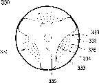
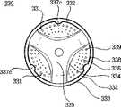
底部330包括扩展区域331,其向滚筒300的外侧突出,以扩大滚筒300的容量。因为扩展区域331沿着滚筒300的轴向朝向滚筒300的外侧突出,从而滚筒300的容量变得更大而与向滚筒300的外侧突出的扩展区域331的容量一样大。如图2中所示,为了最大化滚筒300的容量,扩展区域331突出至接近洗涤桶200的内表面的位置,即,洗涤桶200的底部。The bottom 330 includes an
如上所述,滚筒300的底部330具有连接于其上的连接器,并且扩展区域331形成于底部330的区域中,所述区域是底部330的整个区域中未被连接器占据的区域。也就是说,除了底部330上的连接器连接于其上的支座335之外的区域都沿着滚筒300的轴向朝向滚筒300外侧突出,以形成扩展区域331。因为支座335相对于扩展区域331向滚筒300内侧突出,支座335横穿扩展区域331凹陷于底部330的外表面中。连接器安装于在底部330的外表面中凹陷的支座335上。此外,作为一个示例,底部330在扩展区域331中具有设置于其上的多个孔339,以供洗涤水在滚筒300和洗涤桶200之间前后移动。本发明的滚筒300的上述底部330的结构可以按照多种实施例进行实施,稍后将对其进行详述。As described above, the
图4示出根据本发明第一优选实施例的滚筒底部的平面图,图5示出图4中滚筒底部的截面。FIG. 4 shows a plan view of a drum bottom according to a first preferred embodiment of the present invention, and FIG. 5 shows a section of the drum bottom in FIG. 4 .
参照图4和5,支座335具有与支架500互补的形状,以在其上安装具有三个支脚520的连接器(即支架500)。也就是说,有支架500的中心部分510安装于上面的支座335的中心部分占据底部330的中心部分,有支架500的支脚520安装于上面的支座335的分支部从支座335的中心部分朝向底部330的边沿333形成放射状。据此,如图4中所示,底部330的扩展区域331形成于由支座335的中心部分和分支部确定的区域中,并且由底部330的边沿333环绕。Referring to FIGS. 4 and 5, the
参照图5,邻接洗涤桶200的扩展区域331比连接器(即支架500)的表面突出得更多。为此,支座335具有比支架500更深的深度,以防止支架500在滚筒300旋转过程中接触洗涤桶200的内表面。此外,因为支架500的中心部分510具有比支脚520的端部更厚的厚度,从而支座335随着其在径向上从外侧向中心前进而具有更深的深度。Referring to FIG. 5, the
底部330具有基本上均匀的厚度,并且底部330在扩展区域331处的内表面比底部330在支座335处的内表面更加向滚筒300外侧突出。从而,如图5中所示,滚筒330的容量因为扩展区域331确定的容量‘A’而变大。底部330的边沿平行于滚筒300的轴线,其上安装有支架500的支座335利用斜面与扩展区域331相连。底部330的倾斜部334和边沿333之间存在平坦部336,在底部330的平坦部336和边沿333之间存在弯曲段332。同时,在扩展区域331上存在许多孔339,将扩展区域331连接于底部330的边沿333的那部分是圆形的。The bottom 330 has a substantially uniform thickness, and an inner surface of the bottom 330 at the
图6示出根据本发明第二优选实施例的滚筒底部的平面图,图7示出图6中滚筒底部的截面。FIG. 6 shows a plan view of a drum bottom according to a second preferred embodiment of the present invention, and FIG. 7 shows a section of the drum bottom in FIG. 6 .
参照图6和7,可以注意到,除了第二实施例的底部330具有附加地设置以加强底部330的加强肋337a之外,根据本发明第二优选实施例的滚筒底部的结构类似于根据本发明第一优选实施例的滚筒底部的结构,稍后将对其进行说明。Referring to Figures 6 and 7, it can be noticed that the structure of the bottom of the drum according to the second preferred embodiment of the present invention is similar to that according to the present invention, except that the
参照图6和7,底部330的扩展区域331设置有加强肋337a,其从扩展区域331的平坦部336向滚筒内侧突出,以提高底部330的硬度和强度。如图6和7中所示,为每个扩展区域331设置所述加强肋337a,其弧形与底部330同心,具有与底部330的边沿333相同的曲率。如图7中所示,加强肋337a在底部330的表面上与该底部形成一体。当然,加强肋337a可以通过挤压底部330形成。如上所述,一旦为扩展区域331设置了加强肋337a,滚筒300的底部330的硬度和强度就得以提高,从而在滚筒300旋转时最小化振动和变形。Referring to FIGS. 6 and 7 , the
图8示出根据本发明第三优选实施例的滚筒底部的平面图,图9示出图8中滚筒底部的截面。FIG. 8 shows a plan view of a drum bottom according to a third preferred embodiment of the present invention, and FIG. 9 shows a section of the drum bottom in FIG. 8 .
参照图8和9,根据本发明第三优选实施例的滚筒底部包括形成在扩展区域331上的加强肋337b,以提高底部的硬度和强度。然而,与第二实施例不同的是,设置于底部330的第三实施例的加强肋337b沿着底部330的径向形成。加强肋337b从边沿333或者底部330的圆形部332向倾斜部334延伸。如图9中所示,加强肋337b是通过向滚筒300内侧挤压扩展区域331的一部分而形成的。8 and 9, the drum bottom according to the third preferred embodiment of the present invention includes reinforcing
图10示出根据本发明第四优选实施例的滚筒底部的平面图,图11示出图10中滚筒底部的截面。FIG. 10 shows a plan view of a drum bottom according to a fourth preferred embodiment of the present invention, and FIG. 11 shows a section of the drum bottom in FIG. 10 .
参照图10和11,根据本发明第四优选实施例的滚筒底部的扩展区域331不仅设置有加强肋337b,而且设置有台阶部338。因为加强肋337b具有与第三实施例相同的结构,下面将对台阶部338进行说明。为扩展区域331设置台阶部338,以提高底部330的硬度和强度。如图10和11中所示,台阶部形成为与滚筒330的边沿333同心。换句话说,台阶部338的曲率中心是滚筒300的轴线。台阶部338平行于滚筒300的轴线。当然,台阶部338的结构并不局限于此,而是可以倾斜于该轴线形成。Referring to FIGS. 10 and 11 , the
如上所述,如果为底部330设置有台阶部338,如图11中所示,相对于台阶部338,扩展区域331在邻近底部330的中心的部分比在邻近底部330的边沿333的部分朝向滚筒300的外侧突出得更多。即,扩展区域331包括:第一部分,其邻近底部330的边沿333并从连接器连接于其上的部分突出预定距离;以及第二部分,其邻近底部330的中心并进一步从第一部分突出预定距离。As mentioned above, if the
图12示出根据本发明第五优选实施例的滚筒底部的平面图,图13示出图12中滚筒底部的截面。FIG. 12 shows a plan view of a drum bottom according to a fifth preferred embodiment of the present invention, and FIG. 13 shows a section of the drum bottom in FIG. 12 .
参照以上附图,根据本发明第五优选实施例的滚筒底部的扩展区域331设置有台阶部338和突出部337c。台阶部具有与第四实施例相同的结构。然而,如图13中所示,台阶部338可以关于滚筒300的轴线倾斜。当然,台阶部的结构并不局限于此,台阶部可以平行于该轴线。从台阶部338朝向底部330的径向突出的突出部337c提高底部330的硬度和强度。例如,如图12中所示,突出部337c从台阶部338朝向滚筒300的轴线突出。然而,突出部337c的结构并不局限于此,突出部337c可以在与上述方向相对的方向上突出。Referring to the above drawings, the
同时,滚筒300的底部330受到挤压,稍后将对其进行更详细说明。首先,提供具有均匀厚度的圆板,以制造底部330。当将向底部330提供图6和7中所示的加强肋337a时,可以将具有从一侧突出的加强肋的圆板提供为所述圆板。然而,如果是通过挤压形成加强肋337a,则提供基本上具有相同厚度的圆板,以制造底部330。At the same time, the
首先,所提供的圆板受到挤压,以得到用于扩展滚筒300的容量的空间。在第一次挤压中,板中心部相对于板边沿被向后挤压。在第一次挤压中,形成底部330的平行于滚筒300轴线的边沿333。此外,通过第一次挤压,得到从进行挤压前的一位置向后凹陷的扩展区域331。此外,通过第一次挤压,形成底部330的边沿333和扩展区域之间的圆形部332。通过第一次加压,至少一个肋337a或者337b可以形成于扩展区域331中。如上所述,加强肋337a或337b是与底部330同心并且具有与边沿333相同曲率的弧形,或者沿着底部330的径向形成。同样,在第一次挤压中,与底部330的边沿333同心的台阶部338可以形成于扩展区域331中。当然,在第一次挤压中,突出部337c可以与台阶部338一起形成。First, the provided circular plate is squeezed to obtain a space for expanding the capacity of the
在第一次挤压中至少得到扩展区域331,进行第二次挤压,以形成供连接器(即支架500)连接于其上的支座335。在第二次挤压中,在第一次挤压中突出的部分(即扩展区域331)的一部分在与扩展区域331突出的方向相对的方向上受到挤压。因为已经详细说明了支座335的结构,将省略对其进行的相应说明。同时,第二次挤压中形成的支座335的位置与板在第一次挤压前的位置相同,或者位于板在第一次挤压前的位置和板在第一次挤压后的位置(即扩展区域331)之间。同时,如上所述,加强肋337a或337b和突出部337c可以在第一次挤压中形成。然而,加强肋337a或337b和突出部337c也可以不形成于第一次挤压中,而是形成于第二次挤压中。At least the expanded
同时,如果将在底部330中形成孔339,孔339可以在第一次挤压前、第二次挤压前或者第二次挤压后的任一时间形成。或者,孔339可以在第一次挤压时或者第二次挤压时形成。Meanwhile, if the
下面将说明应用了本发明的滚筒组件的洗衣机的操作。在打开图1中的门150时,将衣物‘m’导入滚筒300中,并使洗衣机进行操作状态,将洗涤水供应至滚筒300和洗涤桶200。此时,因为滚筒330具有因为底部330的扩展区域331的容量‘A’而增大的容量,从而可以将更多衣物投入滚筒300中。当完成供应洗涤水时,连接于连接器的驱动部件旋转滚筒300。当滚筒300旋转时,滚筒300中的衣物和洗涤水由升降器321提升和跌落。衣物通过此时产生的摩擦和碰撞以及清洗剂的化学作用而得到洗涤。在完成洗涤时,脏洗涤水通过排水软管34从滚筒300和洗涤桶200排放到洗衣机外部。当完成排放时,向滚筒300和洗涤桶200供水,并且旋转滚筒300,以对衣物进行漂洗。在预先设定的期间内对衣物进行漂洗后,脏水被排放到洗衣机外部,重复以上步骤,以多次漂洗衣物。在完全漂洗后,滚筒300快速旋转,以通过离心力将衣物脱水。在完成快速旋转后,使用者可以打开门150,并从滚筒300中取出衣物。同时,如果洗衣机具有为其提供的干燥功能,在快速旋转后,可以通过向滚筒300供应热气同时旋转滚筒300来完全干燥衣物。The operation of the washing machine to which the drum assembly of the present invention is applied will be explained below. When the
工业应用性Industrial applicability
如上所述,对于本发明的滚筒组件,扩展区域设置于滚筒底部。从而,滚筒的容量因为扩展区域的容量而增加。据此,洗衣机的容量可以变得更大,而不需改变滚筒和洗涤桶的直径或者长度,以允许制造具有更大容量的洗衣机,而无需增加制造成本。即使滚筒容量变得较大,通过为本发明的滚筒底部设置加强肋、台阶部和突出部提高了滚筒的硬度和强度,从而最小化洗衣机操作过程中滚筒的振动和变形。As mentioned above, with the drum assembly of the present invention, the expansion area is provided at the bottom of the drum. Thus, the capacity of the drum is increased due to the capacity of the expansion area. According to this, the capacity of the washing machine can be made larger without changing the diameter or length of the drum and the tub, allowing the washing machine to be manufactured with a larger capacity without increasing the manufacturing cost. Even though the drum capacity becomes larger, the rigidity and strength of the drum are improved by providing the drum bottom of the present invention with reinforcing ribs, steps, and protrusions, thereby minimizing vibration and deformation of the drum during operation of the washing machine.
对于本领域技术人员来说很明显,在不脱离本发明的精神和范围的前提下,可以在本发明中进行各种变形和改变。从而,只要这些变形和改变处于所附权利要求及其同等结构的范围,本发明将涵盖这些变形和改变。It will be apparent to those skilled in the art that various modifications and changes can be made in the present invention without departing from the spirit and scope of the inventions. Therefore, the present invention will cover these modifications and changes as long as they are within the scope of the appended claims and their equivalents.
Claims (61)
Applications Claiming Priority (4)
| Application Number | Priority Date | Filing Date | Title |
|---|---|---|---|
| KR1020040026795 | 2004-04-19 | ||
| KR1020040026795AKR101054408B1 (en) | 2004-04-19 | 2004-04-19 | washer |
| KR10-2004-0026795 | 2004-04-19 | ||
| PCT/KR2005/000443WO2005100672A1 (en) | 2004-04-19 | 2005-03-15 | Drum assembly in washing machine and method for fabricating the same |
Publications (2)
| Publication Number | Publication Date |
|---|---|
| CN1906345Atrue CN1906345A (en) | 2007-01-31 |
| CN1906345B CN1906345B (en) | 2011-07-27 |
Family
ID=36591449
Family Applications (1)
| Application Number | Title | Priority Date | Filing Date |
|---|---|---|---|
| CN2005800014287AExpired - LifetimeCN1906345B (en) | 2004-04-19 | 2005-03-15 | Drum assembly in washing machine and manufacturing method thereof |
Country Status (11)
| Country | Link |
|---|---|
| US (2) | US8011211B2 (en) |
| EP (1) | EP1738009B1 (en) |
| JP (2) | JP4976276B2 (en) |
| KR (1) | KR101054408B1 (en) |
| CN (1) | CN1906345B (en) |
| AT (1) | ATE398200T1 (en) |
| AU (1) | AU2005233475B9 (en) |
| DE (1) | DE602005007477D1 (en) |
| ES (1) | ES2308487T3 (en) |
| RU (1) | RU2326193C2 (en) |
| WO (1) | WO2005100672A1 (en) |
Cited By (1)
| Publication number | Priority date | Publication date | Assignee | Title |
|---|---|---|---|---|
| WO2018166161A1 (en)* | 2017-03-13 | 2018-09-20 | Midea Group Co., Ltd. | Laundry washing machine with adjustable wash capacity |
Families Citing this family (24)
| Publication number | Priority date | Publication date | Assignee | Title |
|---|---|---|---|---|
| JP4854206B2 (en)* | 2005-02-17 | 2012-01-18 | 株式会社東芝 | Drum washing machine |
| KR101275198B1 (en)* | 2005-05-23 | 2013-06-18 | 엘지전자 주식회사 | Drum type washing machine and method for fabricating drum therefor |
| AU2006250175B2 (en)* | 2005-05-23 | 2009-10-29 | Lg Electronics Inc. | Drum type washing machine and method for fabricating drum therefor |
| KR101273587B1 (en) | 2006-06-01 | 2013-06-11 | 삼성전자주식회사 | Drum type washing machine |
| CN101663432A (en)* | 2007-04-02 | 2010-03-03 | 阿塞里克股份有限公司 | A washer/dryer |
| GB0817960D0 (en)* | 2008-10-01 | 2008-11-05 | Andrew Reason Ltd | Drum |
| JP5260448B2 (en)* | 2009-08-27 | 2013-08-14 | 日立アプライアンス株式会社 | Drum washing machine |
| US8454224B1 (en)* | 2009-11-30 | 2013-06-04 | The United States Of America As Represented By The Secretary Of The Army | Fomite tumbler and method of transferring biological material |
| JP2012170680A (en)* | 2011-02-23 | 2012-09-10 | Panasonic Corp | Drum-type washing machine |
| KR101951423B1 (en)* | 2012-10-09 | 2019-04-25 | 엘지전자 주식회사 | A sub-drum structure of a washing machine having a dual-drum and an assembling method of a sub-drum |
| US20130192084A1 (en)* | 2012-01-24 | 2013-08-01 | Electrolux Home Products, Inc. | Automatic Laundry Washer with Active Venting |
| DE102012107891B3 (en)* | 2012-08-28 | 2013-08-01 | Miele & Cie. Kg | Drum for washing machine e.g. household washing machine, has shaft attached at front end, that is provided for rotatably supporting hub and is compressed in axial direction, and tensioning unit extending in axial direction is in cavity |
| DE102013204987A1 (en)* | 2013-03-21 | 2014-09-25 | BSH Bosch und Siemens Hausgeräte GmbH | Laundry drum for a drum washing machine |
| JP6140022B2 (en)* | 2013-07-26 | 2017-05-31 | シャープ株式会社 | Washing machine |
| DE102014206637A1 (en)* | 2014-04-07 | 2015-10-08 | BSH Hausgeräte GmbH | A method for producing a drum base for a laundry drum of a household appliance, laundry drum and household appliance |
| US10326323B2 (en) | 2015-12-11 | 2019-06-18 | Whirlpool Corporation | Multi-component rotor for an electric motor of an appliance |
| US10704180B2 (en) | 2016-09-22 | 2020-07-07 | Whirlpool Corporation | Reinforcing cap for a tub rear wall of an appliance |
| KR102639680B1 (en)* | 2016-12-23 | 2024-02-26 | 삼성전자주식회사 | Washing machine |
| WO2018220870A1 (en)* | 2017-05-30 | 2018-12-06 | シャープ株式会社 | Washing/draining tank and washing machine |
| US10693336B2 (en) | 2017-06-02 | 2020-06-23 | Whirlpool Corporation | Winding configuration electric motor |
| JP2019022625A (en)* | 2017-07-25 | 2019-02-14 | 日立アプライアンス株式会社 | Drum type washing machine |
| KR102711550B1 (en) | 2019-06-27 | 2024-09-27 | 엘지전자 주식회사 | Washing machine and manufacturing method thereof |
| US12392079B2 (en)* | 2021-02-08 | 2025-08-19 | Lg Electronics Inc. | Laundry treating apparatus |
| JP7720528B2 (en)* | 2021-09-27 | 2025-08-08 | パナソニックIpマネジメント株式会社 | washing machine |
Family Cites Families (32)
| Publication number | Priority date | Publication date | Assignee | Title |
|---|---|---|---|---|
| US1472434A (en)* | 1922-11-15 | 1923-10-30 | Blackstone Mfg Company | Cylinder for washing machines |
| GB471970A (en) | 1935-02-14 | 1937-09-15 | Hydraulic Brake Co | Improvements relating to washing and drying machines |
| US2173603A (en)* | 1937-03-06 | 1939-09-19 | Bendix Home Appliance Inc | Cleaning machine |
| US2742772A (en)* | 1953-05-01 | 1956-04-24 | Joseph C Romine | Clothes washing machine with oscillating tub |
| US3147721A (en)* | 1960-07-11 | 1964-09-08 | Reynolds Metals Co | Die for making metal foil lids |
| US3616662A (en)* | 1970-07-17 | 1971-11-02 | Gen Motors Corp | Clothes washer tub having step means for sediment removal |
| GB1388731A (en) | 1971-05-28 | 1975-03-26 | Zanussi A Spa Industrie | Drum for a washing machine or dryer |
| US3805563A (en)* | 1972-10-19 | 1974-04-23 | J Wendorf | Automatic clothes washing machine |
| US3871314A (en)* | 1972-10-20 | 1975-03-18 | Dorn Co V | Method of making folded can ends and folded can end product |
| FR2218423B1 (en) | 1973-02-19 | 1976-09-10 | Amiens Const Electro Mec | |
| DE2432465B2 (en)* | 1974-07-06 | 1977-05-12 | Gebrüder Thielmann AG, 6341 Sechshelden | HORIZONTALLY MOUNTED DRUM FOR A DRUM WASHING MACHINE |
| IT1083527B (en) | 1977-06-17 | 1985-05-21 | Bertolino Riccardo | IMPROVEMENTS IN WASHING MACHINES |
| IT1258088B (en) | 1992-10-29 | 1996-02-20 | Zanussi Elettrodomestici | PROCEDURE FOR THE MANUFACTURE OF PLASTIC BASKET AND BASKET SO OBTAINED. |
| JP3060789B2 (en) | 1993-08-02 | 2000-07-10 | 松下電器産業株式会社 | Automatic washing machine |
| JP3423452B2 (en)* | 1994-11-02 | 2003-07-07 | 日精エー・エス・ビー機械株式会社 | Biaxially stretch blow-molded container and its mold |
| US5746070A (en)* | 1996-06-07 | 1998-05-05 | White Consolidated Industries, Inc. | Plastic and stainless steel horizontal axis spin tub |
| JP3840734B2 (en)* | 1997-03-31 | 2006-11-01 | 松下電器産業株式会社 | Drum washing machine |
| IT1291667B1 (en) | 1997-04-24 | 1999-01-19 | Miramondi Srl | PERFECTED BASKET FOR WASHING MACHINES, DRYERS AND SIMILAR AND PROCEDURE FOR ITS REALIZATION |
| JPH10328478A (en)* | 1997-05-28 | 1998-12-15 | Matsushita Electric Ind Co Ltd | Washing machine |
| US5979195A (en)* | 1998-05-15 | 1999-11-09 | Maytag Corporation | Seal arrangement between inner and outer tubs of a horizontal axis washing machine |
| JP2000229615A (en)* | 1999-02-10 | 2000-08-22 | Mitsubishi Plastics Ind Ltd | Plastic bottle |
| JP3567097B2 (en) | 1999-03-10 | 2004-09-15 | 株式会社東芝 | Drum type washing machine |
| TW470801B (en)* | 1999-03-31 | 2002-01-01 | Toshiba Corp | Drum type washing machine |
| JP2000325692A (en)* | 1999-05-21 | 2000-11-28 | Toshiba Corp | Drum type washing machine |
| US6460382B1 (en)* | 1999-10-18 | 2002-10-08 | Lg Electronics Inc. | Structure of driving unit in drum type washing machine |
| JP3772821B2 (en) | 2001-10-23 | 2006-05-10 | エルジー電子株式会社 | Washing machine |
| KR100445655B1 (en)* | 2002-01-09 | 2004-08-21 | 엘지전자 주식회사 | A drum's structure of the drum type washer |
| KR100445654B1 (en)* | 2002-01-09 | 2004-08-21 | 엘지전자 주식회사 | A lifter's installing structure of the drum type washer |
| JP3817502B2 (en)* | 2002-08-30 | 2006-09-06 | 株式会社東芝 | Drum washing machine |
| JP2004105250A (en)* | 2002-09-13 | 2004-04-08 | Toshiba Corp | Drum type washer / dryer |
| KR20040046955A (en)* | 2002-11-28 | 2004-06-05 | 엘지전자 주식회사 | The structure of drum in washer |
| AU2004203022B2 (en)* | 2003-07-08 | 2010-01-28 | Lg Electronics Inc. | Drum-type washing machine |
- 2004
- 2004-04-19KRKR1020040026795Apatent/KR101054408B1/ennot_activeExpired - Fee Related
- 2004-10-21USUS10/969,057patent/US8011211B2/enactiveActive
- 2005
- 2005-03-15ATAT05738302Tpatent/ATE398200T1/ennot_activeIP Right Cessation
- 2005-03-15WOPCT/KR2005/000443patent/WO2005100672A1/ennot_activeApplication Discontinuation
- 2005-03-15CNCN2005800014287Apatent/CN1906345B/ennot_activeExpired - Lifetime
- 2005-03-15RURU2006118684/12Apatent/RU2326193C2/ennot_activeIP Right Cessation
- 2005-03-15AUAU2005233475Apatent/AU2005233475B9/ennot_activeExpired
- 2005-03-15ESES05738302Tpatent/ES2308487T3/ennot_activeExpired - Lifetime
- 2005-03-15JPJP2007501702Apatent/JP4976276B2/ennot_activeExpired - Lifetime
- 2005-03-15DEDE602005007477Tpatent/DE602005007477D1/ennot_activeExpired - Lifetime
- 2005-03-15EPEP05738302Apatent/EP1738009B1/ennot_activeExpired - Lifetime
- 2009
- 2009-12-04USUS12/591,944patent/US20100139074A1/ennot_activeAbandoned
- 2010
- 2010-09-13JPJP2010204450Apatent/JP2011011066A/enactivePending
Cited By (3)
| Publication number | Priority date | Publication date | Assignee | Title |
|---|---|---|---|---|
| WO2018166161A1 (en)* | 2017-03-13 | 2018-09-20 | Midea Group Co., Ltd. | Laundry washing machine with adjustable wash capacity |
| US11629448B2 (en) | 2017-03-13 | 2023-04-18 | Midea Group Co., Ltd. | Laundry washing machine with adjustable wash capacity |
| US12421645B2 (en) | 2017-03-13 | 2025-09-23 | Midea Group Co., Ltd. | Laundry washing machine with adjustable wash capacity |
Also Published As
| Publication number | Publication date |
|---|---|
| US20050229651A1 (en) | 2005-10-20 |
| US8011211B2 (en) | 2011-09-06 |
| JP2011011066A (en) | 2011-01-20 |
| JP2007526811A (en) | 2007-09-20 |
| JP4976276B2 (en) | 2012-07-18 |
| AU2005233475A1 (en) | 2005-10-27 |
| RU2326193C2 (en) | 2008-06-10 |
| WO2005100672A1 (en) | 2005-10-27 |
| CN1906345B (en) | 2011-07-27 |
| AU2005233475B2 (en) | 2008-09-25 |
| EP1738009B1 (en) | 2008-06-11 |
| EP1738009A1 (en) | 2007-01-03 |
| AU2005233475B9 (en) | 2008-11-06 |
| ATE398200T1 (en) | 2008-07-15 |
| KR101054408B1 (en) | 2011-08-05 |
| US20100139074A1 (en) | 2010-06-10 |
| ES2308487T3 (en) | 2008-12-01 |
| DE602005007477D1 (en) | 2008-07-24 |
| KR20050101705A (en) | 2005-10-25 |
| RU2006118684A (en) | 2007-12-10 |
Similar Documents
| Publication | Publication Date | Title |
|---|---|---|
| CN1906345A (en) | Drum assembly in washing machine and method for fabricating the same | |
| CN101089277B (en) | Washer and method of forming drum thereof | |
| US20130081432A1 (en) | Lifter and washing machine having the same | |
| AU2004203379C1 (en) | Washing machine | |
| US9062405B2 (en) | Drum type washing machine and method for fabricating drum therefor | |
| CN1912226A (en) | Drum washing machine | |
| US9284676B2 (en) | Drum type washing machine | |
| CN1821478A (en) | front load washing machine | |
| CN107923106B (en) | washing machine | |
| CN1277015C (en) | Washers and Dryers with Improved Plumbing Construction | |
| TW202237935A (en) | Laundry treatment apparatus | |
| CN1928209A (en) | Drum washing machine | |
| US7171828B2 (en) | Washing machine | |
| TW201116661A (en) | Drum type washing machine | |
| US12012687B2 (en) | Laundry treating apparatus | |
| US11566364B2 (en) | Laundry treating apparatus | |
| CN1898431A (en) | Washing machine drum | |
| CN116024780A (en) | Clothes treating apparatus | |
| CN1443892A (en) | Washing machine | |
| CN1876940A (en) | Top cover connecting structure for washing machine | |
| KR20050114332A (en) | A assembly structure of a washing machine's console, and a assembly method |
Legal Events
| Date | Code | Title | Description |
|---|---|---|---|
| C06 | Publication | ||
| PB01 | Publication | ||
| C10 | Entry into substantive examination | ||
| SE01 | Entry into force of request for substantive examination | ||
| C14 | Grant of patent or utility model | ||
| GR01 | Patent grant | ||
| CX01 | Expiry of patent term | ||
| CX01 | Expiry of patent term | Granted publication date:20110727 |