CN1906037A - High-speed digital print device - Google Patents
High-speed digital print deviceDownload PDFInfo
- Publication number
- CN1906037A CN1906037ACNA2004800407760ACN200480040776ACN1906037ACN 1906037 ACN1906037 ACN 1906037ACN A2004800407760 ACNA2004800407760 ACN A2004800407760ACN 200480040776 ACN200480040776 ACN 200480040776ACN 1906037 ACN1906037 ACN 1906037A
- Authority
- CN
- China
- Prior art keywords
- printer
- medium
- printhead
- speed
- Prior art date
- Legal status (The legal status is an assumption and is not a legal conclusion. Google has not performed a legal analysis and makes no representation as to the accuracy of the status listed.)
- Granted
Links
- 238000007639printingMethods0.000claimsabstractdescription44
- 230000007246mechanismEffects0.000claimsdescription44
- 230000005540biological transmissionEffects0.000claimsdescription24
- 238000012423maintenanceMethods0.000claimsdescription20
- 239000012530fluidSubstances0.000claimsdescription17
- 238000005259measurementMethods0.000claimsdescription12
- 238000007789sealingMethods0.000claimsdescription9
- 238000011144upstream manufacturingMethods0.000claimsdescription4
- 230000002093peripheral effectEffects0.000claims1
- 239000000976inkSubstances0.000description87
- 238000000275quality assuranceMethods0.000description24
- 239000000123paperSubstances0.000description21
- 210000003128headAnatomy0.000description15
- 239000007921spraySubstances0.000description15
- 238000000034methodMethods0.000description14
- VYPSYNLAJGMNEJ-UHFFFAOYSA-NSilicium dioxideChemical compoundO=[Si]=OVYPSYNLAJGMNEJ-UHFFFAOYSA-N0.000description12
- 238000010586diagramMethods0.000description9
- 230000000694effectsEffects0.000description9
- 230000033001locomotionEffects0.000description9
- 230000008569processEffects0.000description9
- 230000006835compressionEffects0.000description8
- 238000007906compressionMethods0.000description8
- 238000002347injectionMethods0.000description8
- 239000007924injectionSubstances0.000description8
- 238000012545processingMethods0.000description8
- 230000008859changeEffects0.000description7
- 238000004891communicationMethods0.000description6
- 230000006870functionEffects0.000description6
- 239000000377silicon dioxideSubstances0.000description6
- 230000000007visual effectEffects0.000description6
- 239000000834fixativeSubstances0.000description5
- 235000012239silicon dioxideNutrition0.000description5
- 239000004698PolyethyleneSubstances0.000description4
- 238000013461designMethods0.000description4
- 230000005059dormancyEffects0.000description4
- 238000005516engineering processMethods0.000description4
- 239000000463materialSubstances0.000description4
- -1polyethylenePolymers0.000description4
- 229920000573polyethylenePolymers0.000description4
- XUIMIQQOPSSXEZ-UHFFFAOYSA-NSiliconChemical compound[Si]XUIMIQQOPSSXEZ-UHFFFAOYSA-N0.000description3
- NRTOMJZYCJJWKI-UHFFFAOYSA-NTitanium nitrideChemical compound[Ti]#NNRTOMJZYCJJWKI-UHFFFAOYSA-N0.000description3
- 239000004411aluminiumSubstances0.000description3
- 229910052782aluminiumInorganic materials0.000description3
- XAGFODPZIPBFFR-UHFFFAOYSA-NaluminiumChemical compound[Al]XAGFODPZIPBFFR-UHFFFAOYSA-N0.000description3
- 239000003086colorantSubstances0.000description3
- 230000006837decompressionEffects0.000description3
- 238000009792diffusion processMethods0.000description3
- 238000011049fillingMethods0.000description3
- 238000004519manufacturing processMethods0.000description3
- 229910052751metalInorganic materials0.000description3
- 239000002184metalSubstances0.000description3
- 230000002829reductive effectEffects0.000description3
- 230000000284resting effectEffects0.000description3
- 229910052710siliconInorganic materials0.000description3
- 239000010703siliconSubstances0.000description3
- 230000003068static effectEffects0.000description3
- 229910052581Si3N4Inorganic materials0.000description2
- 238000013459approachMethods0.000description2
- 230000004888barrier functionEffects0.000description2
- 230000009286beneficial effectEffects0.000description2
- 230000015572biosynthetic processEffects0.000description2
- 230000008602contractionEffects0.000description2
- 230000008878couplingEffects0.000description2
- 238000010168coupling processMethods0.000description2
- 238000005859coupling reactionMethods0.000description2
- 238000001035dryingMethods0.000description2
- 238000011156evaluationMethods0.000description2
- 230000014509gene expressionEffects0.000description2
- 238000010438heat treatmentMethods0.000description2
- 230000006698inductionEffects0.000description2
- 238000007641inkjet printingMethods0.000description2
- 230000000670limiting effectEffects0.000description2
- 238000011068loading methodMethods0.000description2
- 230000036961partial effectEffects0.000description2
- 238000002161passivationMethods0.000description2
- 238000000926separation methodMethods0.000description2
- HQVNEWCFYHHQES-UHFFFAOYSA-Nsilicon nitrideChemical groupN12[Si]34N5[Si]62N3[Si]51N64HQVNEWCFYHHQES-UHFFFAOYSA-N0.000description2
- 238000005507sprayingMethods0.000description2
- 239000000758substrateSubstances0.000description2
- 238000012360testing methodMethods0.000description2
- 238000012546transferMethods0.000description2
- VAHKBZSAUKPEOV-UHFFFAOYSA-N1,4-dichloro-2-(4-chlorophenyl)benzeneChemical compoundC1=CC(Cl)=CC=C1C1=CC(Cl)=CC=C1ClVAHKBZSAUKPEOV-UHFFFAOYSA-N0.000description1
- 241001269238DataSpecies0.000description1
- 230000009471actionEffects0.000description1
- 230000004913activationEffects0.000description1
- 238000005452bendingMethods0.000description1
- 238000006243chemical reactionMethods0.000description1
- 238000010073coating (rubber)Methods0.000description1
- 239000011248coating agentSubstances0.000description1
- 238000000576coating methodMethods0.000description1
- 230000000052comparative effectEffects0.000description1
- 238000010276constructionMethods0.000description1
- 238000001816coolingMethods0.000description1
- 239000007799corkSubstances0.000description1
- 230000032798delaminationEffects0.000description1
- 230000008034disappearanceEffects0.000description1
- 239000006185dispersionSubstances0.000description1
- 238000006073displacement reactionMethods0.000description1
- 230000005611electricityEffects0.000description1
- 238000001704evaporationMethods0.000description1
- 230000008020evaporationEffects0.000description1
- 210000000887faceAnatomy0.000description1
- 239000011521glassSubstances0.000description1
- XLYOFNOQVPJJNP-UHFFFAOYSA-MhydroxideChemical compound[OH-]XLYOFNOQVPJJNP-UHFFFAOYSA-M0.000description1
- 230000001771impaired effectEffects0.000description1
- 230000006872improvementEffects0.000description1
- 238000003780insertionMethods0.000description1
- 230000037431insertionEffects0.000description1
- 238000009434installationMethods0.000description1
- 230000003993interactionEffects0.000description1
- 230000002045lasting effectEffects0.000description1
- 210000003141lower extremityAnatomy0.000description1
- 239000011159matrix materialSubstances0.000description1
- 238000002156mixingMethods0.000description1
- 238000012544monitoring processMethods0.000description1
- 238000000465mouldingMethods0.000description1
- 238000012856packingMethods0.000description1
- 239000011087paperboardSubstances0.000description1
- 201000007094prostatitisDiseases0.000description1
- 230000009467reductionEffects0.000description1
- 230000008439repair processEffects0.000description1
- 230000000630rising effectEffects0.000description1
- 125000006850spacer groupChemical group0.000description1
- 238000001228spectrumMethods0.000description1
- 239000000126substanceSubstances0.000description1
- 238000004381surface treatmentMethods0.000description1
- 238000003786synthesis reactionMethods0.000description1
- 230000008719thickeningEffects0.000description1
Images


Classifications
- B—PERFORMING OPERATIONS; TRANSPORTING
- B41—PRINTING; LINING MACHINES; TYPEWRITERS; STAMPS
- B41J—TYPEWRITERS; SELECTIVE PRINTING MECHANISMS, i.e. MECHANISMS PRINTING OTHERWISE THAN FROM A FORME; CORRECTION OF TYPOGRAPHICAL ERRORS
- B41J2/00—Typewriters or selective printing mechanisms characterised by the printing or marking process for which they are designed
- B41J2/005—Typewriters or selective printing mechanisms characterised by the printing or marking process for which they are designed characterised by bringing liquid or particles selectively into contact with a printing material
- B41J2/01—Ink jet
- B41J2/17—Ink jet characterised by ink handling
- B41J2/175—Ink supply systems ; Circuit parts therefor
- B—PERFORMING OPERATIONS; TRANSPORTING
- B41—PRINTING; LINING MACHINES; TYPEWRITERS; STAMPS
- B41J—TYPEWRITERS; SELECTIVE PRINTING MECHANISMS, i.e. MECHANISMS PRINTING OTHERWISE THAN FROM A FORME; CORRECTION OF TYPOGRAPHICAL ERRORS
- B41J25/00—Actions or mechanisms not otherwise provided for
- B41J25/34—Bodily-changeable print heads or carriages
- B—PERFORMING OPERATIONS; TRANSPORTING
- B41—PRINTING; LINING MACHINES; TYPEWRITERS; STAMPS
- B41J—TYPEWRITERS; SELECTIVE PRINTING MECHANISMS, i.e. MECHANISMS PRINTING OTHERWISE THAN FROM A FORME; CORRECTION OF TYPOGRAPHICAL ERRORS
- B41J2/00—Typewriters or selective printing mechanisms characterised by the printing or marking process for which they are designed
- B41J2/005—Typewriters or selective printing mechanisms characterised by the printing or marking process for which they are designed characterised by bringing liquid or particles selectively into contact with a printing material
- B41J2/01—Ink jet
- B41J2/015—Ink jet characterised by the jet generation process
- B41J2/04—Ink jet characterised by the jet generation process generating single droplets or particles on demand
- B41J2/045—Ink jet characterised by the jet generation process generating single droplets or particles on demand by pressure, e.g. electromechanical transducers
- B41J2/04501—Control methods or devices therefor, e.g. driver circuits, control circuits
- B41J2/04541—Specific driving circuit
- B—PERFORMING OPERATIONS; TRANSPORTING
- B41—PRINTING; LINING MACHINES; TYPEWRITERS; STAMPS
- B41J—TYPEWRITERS; SELECTIVE PRINTING MECHANISMS, i.e. MECHANISMS PRINTING OTHERWISE THAN FROM A FORME; CORRECTION OF TYPOGRAPHICAL ERRORS
- B41J2/00—Typewriters or selective printing mechanisms characterised by the printing or marking process for which they are designed
- B41J2/005—Typewriters or selective printing mechanisms characterised by the printing or marking process for which they are designed characterised by bringing liquid or particles selectively into contact with a printing material
- B41J2/01—Ink jet
- B41J2/015—Ink jet characterised by the jet generation process
- B41J2/04—Ink jet characterised by the jet generation process generating single droplets or particles on demand
- B41J2/045—Ink jet characterised by the jet generation process generating single droplets or particles on demand by pressure, e.g. electromechanical transducers
- B41J2/04501—Control methods or devices therefor, e.g. driver circuits, control circuits
- B41J2/04543—Block driving
- B—PERFORMING OPERATIONS; TRANSPORTING
- B41—PRINTING; LINING MACHINES; TYPEWRITERS; STAMPS
- B41J—TYPEWRITERS; SELECTIVE PRINTING MECHANISMS, i.e. MECHANISMS PRINTING OTHERWISE THAN FROM A FORME; CORRECTION OF TYPOGRAPHICAL ERRORS
- B41J2/00—Typewriters or selective printing mechanisms characterised by the printing or marking process for which they are designed
- B41J2/005—Typewriters or selective printing mechanisms characterised by the printing or marking process for which they are designed characterised by bringing liquid or particles selectively into contact with a printing material
- B41J2/01—Ink jet
- B41J2/015—Ink jet characterised by the jet generation process
- B41J2/04—Ink jet characterised by the jet generation process generating single droplets or particles on demand
- B41J2/045—Ink jet characterised by the jet generation process generating single droplets or particles on demand by pressure, e.g. electromechanical transducers
- B41J2/04501—Control methods or devices therefor, e.g. driver circuits, control circuits
- B41J2/0458—Control methods or devices therefor, e.g. driver circuits, control circuits controlling heads based on heating elements forming bubbles
- B—PERFORMING OPERATIONS; TRANSPORTING
- B41—PRINTING; LINING MACHINES; TYPEWRITERS; STAMPS
- B41J—TYPEWRITERS; SELECTIVE PRINTING MECHANISMS, i.e. MECHANISMS PRINTING OTHERWISE THAN FROM A FORME; CORRECTION OF TYPOGRAPHICAL ERRORS
- B41J2/00—Typewriters or selective printing mechanisms characterised by the printing or marking process for which they are designed
- B41J2/005—Typewriters or selective printing mechanisms characterised by the printing or marking process for which they are designed characterised by bringing liquid or particles selectively into contact with a printing material
- B41J2/01—Ink jet
- B41J2/015—Ink jet characterised by the jet generation process
- B41J2/04—Ink jet characterised by the jet generation process generating single droplets or particles on demand
- B41J2/045—Ink jet characterised by the jet generation process generating single droplets or particles on demand by pressure, e.g. electromechanical transducers
- B41J2/04501—Control methods or devices therefor, e.g. driver circuits, control circuits
- B41J2/04585—Control methods or devices therefor, e.g. driver circuits, control circuits controlling heads based on thermal bent actuators
- B—PERFORMING OPERATIONS; TRANSPORTING
- B41—PRINTING; LINING MACHINES; TYPEWRITERS; STAMPS
- B41J—TYPEWRITERS; SELECTIVE PRINTING MECHANISMS, i.e. MECHANISMS PRINTING OTHERWISE THAN FROM A FORME; CORRECTION OF TYPOGRAPHICAL ERRORS
- B41J2/00—Typewriters or selective printing mechanisms characterised by the printing or marking process for which they are designed
- B41J2/005—Typewriters or selective printing mechanisms characterised by the printing or marking process for which they are designed characterised by bringing liquid or particles selectively into contact with a printing material
- B41J2/01—Ink jet
- B41J2/015—Ink jet characterised by the jet generation process
- B41J2/04—Ink jet characterised by the jet generation process generating single droplets or particles on demand
- B41J2/045—Ink jet characterised by the jet generation process generating single droplets or particles on demand by pressure, e.g. electromechanical transducers
- B41J2/04501—Control methods or devices therefor, e.g. driver circuits, control circuits
- B41J2/04591—Width of the driving signal being adjusted
- B—PERFORMING OPERATIONS; TRANSPORTING
- B41—PRINTING; LINING MACHINES; TYPEWRITERS; STAMPS
- B41J—TYPEWRITERS; SELECTIVE PRINTING MECHANISMS, i.e. MECHANISMS PRINTING OTHERWISE THAN FROM A FORME; CORRECTION OF TYPOGRAPHICAL ERRORS
- B41J2/00—Typewriters or selective printing mechanisms characterised by the printing or marking process for which they are designed
- B41J2/005—Typewriters or selective printing mechanisms characterised by the printing or marking process for which they are designed characterised by bringing liquid or particles selectively into contact with a printing material
- B41J2/01—Ink jet
- B41J2/135—Nozzles
- B41J2/14—Structure thereof only for on-demand ink jet heads
- B41J2/14016—Structure of bubble jet print heads
- B—PERFORMING OPERATIONS; TRANSPORTING
- B41—PRINTING; LINING MACHINES; TYPEWRITERS; STAMPS
- B41J—TYPEWRITERS; SELECTIVE PRINTING MECHANISMS, i.e. MECHANISMS PRINTING OTHERWISE THAN FROM A FORME; CORRECTION OF TYPOGRAPHICAL ERRORS
- B41J2/00—Typewriters or selective printing mechanisms characterised by the printing or marking process for which they are designed
- B41J2/005—Typewriters or selective printing mechanisms characterised by the printing or marking process for which they are designed characterised by bringing liquid or particles selectively into contact with a printing material
- B41J2/01—Ink jet
- B41J2/135—Nozzles
- B41J2/14—Structure thereof only for on-demand ink jet heads
- B41J2/14427—Structure of ink jet print heads with thermal bend detached actuators
- B—PERFORMING OPERATIONS; TRANSPORTING
- B41—PRINTING; LINING MACHINES; TYPEWRITERS; STAMPS
- B41J—TYPEWRITERS; SELECTIVE PRINTING MECHANISMS, i.e. MECHANISMS PRINTING OTHERWISE THAN FROM A FORME; CORRECTION OF TYPOGRAPHICAL ERRORS
- B41J2/00—Typewriters or selective printing mechanisms characterised by the printing or marking process for which they are designed
- B41J2/005—Typewriters or selective printing mechanisms characterised by the printing or marking process for which they are designed characterised by bringing liquid or particles selectively into contact with a printing material
- B41J2/01—Ink jet
- B41J2/135—Nozzles
- B41J2/145—Arrangement thereof
- B41J2/155—Arrangement thereof for line printing
- B—PERFORMING OPERATIONS; TRANSPORTING
- B41—PRINTING; LINING MACHINES; TYPEWRITERS; STAMPS
- B41J—TYPEWRITERS; SELECTIVE PRINTING MECHANISMS, i.e. MECHANISMS PRINTING OTHERWISE THAN FROM A FORME; CORRECTION OF TYPOGRAPHICAL ERRORS
- B41J2/00—Typewriters or selective printing mechanisms characterised by the printing or marking process for which they are designed
- B41J2/005—Typewriters or selective printing mechanisms characterised by the printing or marking process for which they are designed characterised by bringing liquid or particles selectively into contact with a printing material
- B41J2/01—Ink jet
- B41J2/135—Nozzles
- B41J2/16—Production of nozzles
- B41J2/1621—Manufacturing processes
- B41J2/1623—Manufacturing processes bonding and adhesion
- B—PERFORMING OPERATIONS; TRANSPORTING
- B41—PRINTING; LINING MACHINES; TYPEWRITERS; STAMPS
- B41J—TYPEWRITERS; SELECTIVE PRINTING MECHANISMS, i.e. MECHANISMS PRINTING OTHERWISE THAN FROM A FORME; CORRECTION OF TYPOGRAPHICAL ERRORS
- B41J2/00—Typewriters or selective printing mechanisms characterised by the printing or marking process for which they are designed
- B41J2/005—Typewriters or selective printing mechanisms characterised by the printing or marking process for which they are designed characterised by bringing liquid or particles selectively into contact with a printing material
- B41J2/01—Ink jet
- B41J2/135—Nozzles
- B41J2/16—Production of nozzles
- B41J2/1621—Manufacturing processes
- B41J2/1626—Manufacturing processes etching
- B41J2/1628—Manufacturing processes etching dry etching
- B—PERFORMING OPERATIONS; TRANSPORTING
- B41—PRINTING; LINING MACHINES; TYPEWRITERS; STAMPS
- B41J—TYPEWRITERS; SELECTIVE PRINTING MECHANISMS, i.e. MECHANISMS PRINTING OTHERWISE THAN FROM A FORME; CORRECTION OF TYPOGRAPHICAL ERRORS
- B41J2/00—Typewriters or selective printing mechanisms characterised by the printing or marking process for which they are designed
- B41J2/005—Typewriters or selective printing mechanisms characterised by the printing or marking process for which they are designed characterised by bringing liquid or particles selectively into contact with a printing material
- B41J2/01—Ink jet
- B41J2/135—Nozzles
- B41J2/16—Production of nozzles
- B41J2/1621—Manufacturing processes
- B41J2/1632—Manufacturing processes machining
- B41J2/1634—Manufacturing processes machining laser machining
- B—PERFORMING OPERATIONS; TRANSPORTING
- B41—PRINTING; LINING MACHINES; TYPEWRITERS; STAMPS
- B41J—TYPEWRITERS; SELECTIVE PRINTING MECHANISMS, i.e. MECHANISMS PRINTING OTHERWISE THAN FROM A FORME; CORRECTION OF TYPOGRAPHICAL ERRORS
- B41J2/00—Typewriters or selective printing mechanisms characterised by the printing or marking process for which they are designed
- B41J2/005—Typewriters or selective printing mechanisms characterised by the printing or marking process for which they are designed characterised by bringing liquid or particles selectively into contact with a printing material
- B41J2/01—Ink jet
- B41J2/135—Nozzles
- B41J2/16—Production of nozzles
- B41J2/1621—Manufacturing processes
- B41J2/1637—Manufacturing processes molding
- B—PERFORMING OPERATIONS; TRANSPORTING
- B41—PRINTING; LINING MACHINES; TYPEWRITERS; STAMPS
- B41J—TYPEWRITERS; SELECTIVE PRINTING MECHANISMS, i.e. MECHANISMS PRINTING OTHERWISE THAN FROM A FORME; CORRECTION OF TYPOGRAPHICAL ERRORS
- B41J2/00—Typewriters or selective printing mechanisms characterised by the printing or marking process for which they are designed
- B41J2/005—Typewriters or selective printing mechanisms characterised by the printing or marking process for which they are designed characterised by bringing liquid or particles selectively into contact with a printing material
- B41J2/01—Ink jet
- B41J2/135—Nozzles
- B41J2/16—Production of nozzles
- B41J2/1621—Manufacturing processes
- B41J2/164—Manufacturing processes thin film formation
- B41J2/1642—Manufacturing processes thin film formation thin film formation by CVD [chemical vapor deposition]
- B—PERFORMING OPERATIONS; TRANSPORTING
- B41—PRINTING; LINING MACHINES; TYPEWRITERS; STAMPS
- B41J—TYPEWRITERS; SELECTIVE PRINTING MECHANISMS, i.e. MECHANISMS PRINTING OTHERWISE THAN FROM A FORME; CORRECTION OF TYPOGRAPHICAL ERRORS
- B41J2/00—Typewriters or selective printing mechanisms characterised by the printing or marking process for which they are designed
- B41J2/005—Typewriters or selective printing mechanisms characterised by the printing or marking process for which they are designed characterised by bringing liquid or particles selectively into contact with a printing material
- B41J2/01—Ink jet
- B41J2/135—Nozzles
- B41J2/16—Production of nozzles
- B41J2/1648—Production of print heads with thermal bend detached actuators
- B—PERFORMING OPERATIONS; TRANSPORTING
- B41—PRINTING; LINING MACHINES; TYPEWRITERS; STAMPS
- B41J—TYPEWRITERS; SELECTIVE PRINTING MECHANISMS, i.e. MECHANISMS PRINTING OTHERWISE THAN FROM A FORME; CORRECTION OF TYPOGRAPHICAL ERRORS
- B41J2/00—Typewriters or selective printing mechanisms characterised by the printing or marking process for which they are designed
- B41J2/005—Typewriters or selective printing mechanisms characterised by the printing or marking process for which they are designed characterised by bringing liquid or particles selectively into contact with a printing material
- B41J2/01—Ink jet
- B41J2/135—Nozzles
- B41J2/165—Prevention or detection of nozzle clogging, e.g. cleaning, capping or moistening for nozzles
- B41J2/16517—Cleaning of print head nozzles
- B41J2/1652—Cleaning of print head nozzles by driving a fluid through the nozzles to the outside thereof, e.g. by applying pressure to the inside or vacuum at the outside of the print head
- B41J2/16526—Cleaning of print head nozzles by driving a fluid through the nozzles to the outside thereof, e.g. by applying pressure to the inside or vacuum at the outside of the print head by applying pressure only
- B—PERFORMING OPERATIONS; TRANSPORTING
- B41—PRINTING; LINING MACHINES; TYPEWRITERS; STAMPS
- B41J—TYPEWRITERS; SELECTIVE PRINTING MECHANISMS, i.e. MECHANISMS PRINTING OTHERWISE THAN FROM A FORME; CORRECTION OF TYPOGRAPHICAL ERRORS
- B41J2/00—Typewriters or selective printing mechanisms characterised by the printing or marking process for which they are designed
- B41J2/005—Typewriters or selective printing mechanisms characterised by the printing or marking process for which they are designed characterised by bringing liquid or particles selectively into contact with a printing material
- B41J2/01—Ink jet
- B41J2/135—Nozzles
- B41J2/165—Prevention or detection of nozzle clogging, e.g. cleaning, capping or moistening for nozzles
- B41J2/16517—Cleaning of print head nozzles
- B41J2/16535—Cleaning of print head nozzles using wiping constructions
- B—PERFORMING OPERATIONS; TRANSPORTING
- B41—PRINTING; LINING MACHINES; TYPEWRITERS; STAMPS
- B41J—TYPEWRITERS; SELECTIVE PRINTING MECHANISMS, i.e. MECHANISMS PRINTING OTHERWISE THAN FROM A FORME; CORRECTION OF TYPOGRAPHICAL ERRORS
- B41J2/00—Typewriters or selective printing mechanisms characterised by the printing or marking process for which they are designed
- B41J2/005—Typewriters or selective printing mechanisms characterised by the printing or marking process for which they are designed characterised by bringing liquid or particles selectively into contact with a printing material
- B41J2/01—Ink jet
- B41J2/135—Nozzles
- B41J2/165—Prevention or detection of nozzle clogging, e.g. cleaning, capping or moistening for nozzles
- B41J2/16585—Prevention or detection of nozzle clogging, e.g. cleaning, capping or moistening for nozzles for paper-width or non-reciprocating print heads
- B—PERFORMING OPERATIONS; TRANSPORTING
- B41—PRINTING; LINING MACHINES; TYPEWRITERS; STAMPS
- B41J—TYPEWRITERS; SELECTIVE PRINTING MECHANISMS, i.e. MECHANISMS PRINTING OTHERWISE THAN FROM A FORME; CORRECTION OF TYPOGRAPHICAL ERRORS
- B41J2/00—Typewriters or selective printing mechanisms characterised by the printing or marking process for which they are designed
- B41J2/005—Typewriters or selective printing mechanisms characterised by the printing or marking process for which they are designed characterised by bringing liquid or particles selectively into contact with a printing material
- B41J2/01—Ink jet
- B41J2/17—Ink jet characterised by ink handling
- B41J2/1707—Conditioning of the inside of ink supply circuits, e.g. flushing during start-up or shut-down
- B—PERFORMING OPERATIONS; TRANSPORTING
- B41—PRINTING; LINING MACHINES; TYPEWRITERS; STAMPS
- B41J—TYPEWRITERS; SELECTIVE PRINTING MECHANISMS, i.e. MECHANISMS PRINTING OTHERWISE THAN FROM A FORME; CORRECTION OF TYPOGRAPHICAL ERRORS
- B41J2/00—Typewriters or selective printing mechanisms characterised by the printing or marking process for which they are designed
- B41J2/005—Typewriters or selective printing mechanisms characterised by the printing or marking process for which they are designed characterised by bringing liquid or particles selectively into contact with a printing material
- B41J2/01—Ink jet
- B41J2/17—Ink jet characterised by ink handling
- B41J2/1714—Conditioning of the outside of ink supply systems, e.g. inkjet collector cleaning, ink mist removal
- B—PERFORMING OPERATIONS; TRANSPORTING
- B41—PRINTING; LINING MACHINES; TYPEWRITERS; STAMPS
- B41J—TYPEWRITERS; SELECTIVE PRINTING MECHANISMS, i.e. MECHANISMS PRINTING OTHERWISE THAN FROM A FORME; CORRECTION OF TYPOGRAPHICAL ERRORS
- B41J2/00—Typewriters or selective printing mechanisms characterised by the printing or marking process for which they are designed
- B41J2/005—Typewriters or selective printing mechanisms characterised by the printing or marking process for which they are designed characterised by bringing liquid or particles selectively into contact with a printing material
- B41J2/01—Ink jet
- B41J2/17—Ink jet characterised by ink handling
- B41J2/1721—Collecting waste ink; Collectors therefor
- B41J2/1742—Open waste ink collectors, e.g. ink receiving from a print head above the collector during borderless printing
- B—PERFORMING OPERATIONS; TRANSPORTING
- B41—PRINTING; LINING MACHINES; TYPEWRITERS; STAMPS
- B41J—TYPEWRITERS; SELECTIVE PRINTING MECHANISMS, i.e. MECHANISMS PRINTING OTHERWISE THAN FROM A FORME; CORRECTION OF TYPOGRAPHICAL ERRORS
- B41J2/00—Typewriters or selective printing mechanisms characterised by the printing or marking process for which they are designed
- B41J2/005—Typewriters or selective printing mechanisms characterised by the printing or marking process for which they are designed characterised by bringing liquid or particles selectively into contact with a printing material
- B41J2/01—Ink jet
- B41J2/17—Ink jet characterised by ink handling
- B41J2/175—Ink supply systems ; Circuit parts therefor
- B41J2/17503—Ink cartridges
- B41J2/17506—Refilling of the cartridge
- B41J2/17509—Whilst mounted in the printer
- B—PERFORMING OPERATIONS; TRANSPORTING
- B41—PRINTING; LINING MACHINES; TYPEWRITERS; STAMPS
- B41J—TYPEWRITERS; SELECTIVE PRINTING MECHANISMS, i.e. MECHANISMS PRINTING OTHERWISE THAN FROM A FORME; CORRECTION OF TYPOGRAPHICAL ERRORS
- B41J2/00—Typewriters or selective printing mechanisms characterised by the printing or marking process for which they are designed
- B41J2/005—Typewriters or selective printing mechanisms characterised by the printing or marking process for which they are designed characterised by bringing liquid or particles selectively into contact with a printing material
- B41J2/01—Ink jet
- B41J2/17—Ink jet characterised by ink handling
- B41J2/175—Ink supply systems ; Circuit parts therefor
- B41J2/17503—Ink cartridges
- B41J2/17513—Inner structure
- B—PERFORMING OPERATIONS; TRANSPORTING
- B41—PRINTING; LINING MACHINES; TYPEWRITERS; STAMPS
- B41J—TYPEWRITERS; SELECTIVE PRINTING MECHANISMS, i.e. MECHANISMS PRINTING OTHERWISE THAN FROM A FORME; CORRECTION OF TYPOGRAPHICAL ERRORS
- B41J2/00—Typewriters or selective printing mechanisms characterised by the printing or marking process for which they are designed
- B41J2/005—Typewriters or selective printing mechanisms characterised by the printing or marking process for which they are designed characterised by bringing liquid or particles selectively into contact with a printing material
- B41J2/01—Ink jet
- B41J2/17—Ink jet characterised by ink handling
- B41J2/175—Ink supply systems ; Circuit parts therefor
- B41J2/17503—Ink cartridges
- B41J2/1752—Mounting within the printer
- B—PERFORMING OPERATIONS; TRANSPORTING
- B41—PRINTING; LINING MACHINES; TYPEWRITERS; STAMPS
- B41J—TYPEWRITERS; SELECTIVE PRINTING MECHANISMS, i.e. MECHANISMS PRINTING OTHERWISE THAN FROM A FORME; CORRECTION OF TYPOGRAPHICAL ERRORS
- B41J2/00—Typewriters or selective printing mechanisms characterised by the printing or marking process for which they are designed
- B41J2/005—Typewriters or selective printing mechanisms characterised by the printing or marking process for which they are designed characterised by bringing liquid or particles selectively into contact with a printing material
- B41J2/01—Ink jet
- B41J2/17—Ink jet characterised by ink handling
- B41J2/175—Ink supply systems ; Circuit parts therefor
- B41J2/17503—Ink cartridges
- B41J2/17536—Protection of cartridges or parts thereof, e.g. tape
- B—PERFORMING OPERATIONS; TRANSPORTING
- B41—PRINTING; LINING MACHINES; TYPEWRITERS; STAMPS
- B41J—TYPEWRITERS; SELECTIVE PRINTING MECHANISMS, i.e. MECHANISMS PRINTING OTHERWISE THAN FROM A FORME; CORRECTION OF TYPOGRAPHICAL ERRORS
- B41J2/00—Typewriters or selective printing mechanisms characterised by the printing or marking process for which they are designed
- B41J2/005—Typewriters or selective printing mechanisms characterised by the printing or marking process for which they are designed characterised by bringing liquid or particles selectively into contact with a printing material
- B41J2/01—Ink jet
- B41J2/17—Ink jet characterised by ink handling
- B41J2/175—Ink supply systems ; Circuit parts therefor
- B41J2/17503—Ink cartridges
- B41J2/17553—Outer structure
- B—PERFORMING OPERATIONS; TRANSPORTING
- B41—PRINTING; LINING MACHINES; TYPEWRITERS; STAMPS
- B41J—TYPEWRITERS; SELECTIVE PRINTING MECHANISMS, i.e. MECHANISMS PRINTING OTHERWISE THAN FROM A FORME; CORRECTION OF TYPOGRAPHICAL ERRORS
- B41J2/00—Typewriters or selective printing mechanisms characterised by the printing or marking process for which they are designed
- B41J2/005—Typewriters or selective printing mechanisms characterised by the printing or marking process for which they are designed characterised by bringing liquid or particles selectively into contact with a printing material
- B41J2/01—Ink jet
- B41J2/17—Ink jet characterised by ink handling
- B41J2/175—Ink supply systems ; Circuit parts therefor
- B41J2/17503—Ink cartridges
- B41J2/17556—Means for regulating the pressure in the cartridge
- B—PERFORMING OPERATIONS; TRANSPORTING
- B41—PRINTING; LINING MACHINES; TYPEWRITERS; STAMPS
- B41J—TYPEWRITERS; SELECTIVE PRINTING MECHANISMS, i.e. MECHANISMS PRINTING OTHERWISE THAN FROM A FORME; CORRECTION OF TYPOGRAPHICAL ERRORS
- B41J2/00—Typewriters or selective printing mechanisms characterised by the printing or marking process for which they are designed
- B41J2/005—Typewriters or selective printing mechanisms characterised by the printing or marking process for which they are designed characterised by bringing liquid or particles selectively into contact with a printing material
- B41J2/01—Ink jet
- B41J2/17—Ink jet characterised by ink handling
- B41J2/175—Ink supply systems ; Circuit parts therefor
- B41J2/17566—Ink level or ink residue control
- B—PERFORMING OPERATIONS; TRANSPORTING
- B41—PRINTING; LINING MACHINES; TYPEWRITERS; STAMPS
- B41J—TYPEWRITERS; SELECTIVE PRINTING MECHANISMS, i.e. MECHANISMS PRINTING OTHERWISE THAN FROM A FORME; CORRECTION OF TYPOGRAPHICAL ERRORS
- B41J2/00—Typewriters or selective printing mechanisms characterised by the printing or marking process for which they are designed
- B41J2/005—Typewriters or selective printing mechanisms characterised by the printing or marking process for which they are designed characterised by bringing liquid or particles selectively into contact with a printing material
- B41J2/01—Ink jet
- B41J2/17—Ink jet characterised by ink handling
- B41J2/19—Ink jet characterised by ink handling for removing air bubbles
- B—PERFORMING OPERATIONS; TRANSPORTING
- B41—PRINTING; LINING MACHINES; TYPEWRITERS; STAMPS
- B41J—TYPEWRITERS; SELECTIVE PRINTING MECHANISMS, i.e. MECHANISMS PRINTING OTHERWISE THAN FROM A FORME; CORRECTION OF TYPOGRAPHICAL ERRORS
- B41J2/00—Typewriters or selective printing mechanisms characterised by the printing or marking process for which they are designed
- B41J2/485—Typewriters or selective printing mechanisms characterised by the printing or marking process for which they are designed characterised by the process of building-up characters or image elements applicable to two or more kinds of printing or marking processes
- B41J2/505—Typewriters or selective printing mechanisms characterised by the printing or marking process for which they are designed characterised by the process of building-up characters or image elements applicable to two or more kinds of printing or marking processes from an assembly of identical printing elements
- B41J2/515—Typewriters or selective printing mechanisms characterised by the printing or marking process for which they are designed characterised by the process of building-up characters or image elements applicable to two or more kinds of printing or marking processes from an assembly of identical printing elements line printer type
- B—PERFORMING OPERATIONS; TRANSPORTING
- B41—PRINTING; LINING MACHINES; TYPEWRITERS; STAMPS
- B41J—TYPEWRITERS; SELECTIVE PRINTING MECHANISMS, i.e. MECHANISMS PRINTING OTHERWISE THAN FROM A FORME; CORRECTION OF TYPOGRAPHICAL ERRORS
- B41J29/00—Details of, or accessories for, typewriters or selective printing mechanisms not otherwise provided for
- B41J29/02—Framework
- B—PERFORMING OPERATIONS; TRANSPORTING
- B41—PRINTING; LINING MACHINES; TYPEWRITERS; STAMPS
- B41J—TYPEWRITERS; SELECTIVE PRINTING MECHANISMS, i.e. MECHANISMS PRINTING OTHERWISE THAN FROM A FORME; CORRECTION OF TYPOGRAPHICAL ERRORS
- B41J29/00—Details of, or accessories for, typewriters or selective printing mechanisms not otherwise provided for
- B41J29/12—Guards, shields or dust excluders
- B41J29/13—Cases or covers
- B—PERFORMING OPERATIONS; TRANSPORTING
- B41—PRINTING; LINING MACHINES; TYPEWRITERS; STAMPS
- B41J—TYPEWRITERS; SELECTIVE PRINTING MECHANISMS, i.e. MECHANISMS PRINTING OTHERWISE THAN FROM A FORME; CORRECTION OF TYPOGRAPHICAL ERRORS
- B41J29/00—Details of, or accessories for, typewriters or selective printing mechanisms not otherwise provided for
- B41J29/38—Drives, motors, controls or automatic cut-off devices for the entire printing mechanism
- B—PERFORMING OPERATIONS; TRANSPORTING
- B29—WORKING OF PLASTICS; WORKING OF SUBSTANCES IN A PLASTIC STATE IN GENERAL
- B29C—SHAPING OR JOINING OF PLASTICS; SHAPING OF MATERIAL IN A PLASTIC STATE, NOT OTHERWISE PROVIDED FOR; AFTER-TREATMENT OF THE SHAPED PRODUCTS, e.g. REPAIRING
- B29C64/00—Additive manufacturing, i.e. manufacturing of three-dimensional [3D] objects by additive deposition, additive agglomeration or additive layering, e.g. by 3D printing, stereolithography or selective laser sintering
- B29C64/20—Apparatus for additive manufacturing; Details thereof or accessories therefor
- B29C64/205—Means for applying layers
- B29C64/209—Heads; Nozzles
- B—PERFORMING OPERATIONS; TRANSPORTING
- B41—PRINTING; LINING MACHINES; TYPEWRITERS; STAMPS
- B41J—TYPEWRITERS; SELECTIVE PRINTING MECHANISMS, i.e. MECHANISMS PRINTING OTHERWISE THAN FROM A FORME; CORRECTION OF TYPOGRAPHICAL ERRORS
- B41J2/00—Typewriters or selective printing mechanisms characterised by the printing or marking process for which they are designed
- B41J2/005—Typewriters or selective printing mechanisms characterised by the printing or marking process for which they are designed characterised by bringing liquid or particles selectively into contact with a printing material
- B41J2/01—Ink jet
- B41J2/135—Nozzles
- B41J2/14—Structure thereof only for on-demand ink jet heads
- B41J2002/14362—Assembling elements of heads
- B—PERFORMING OPERATIONS; TRANSPORTING
- B41—PRINTING; LINING MACHINES; TYPEWRITERS; STAMPS
- B41J—TYPEWRITERS; SELECTIVE PRINTING MECHANISMS, i.e. MECHANISMS PRINTING OTHERWISE THAN FROM A FORME; CORRECTION OF TYPOGRAPHICAL ERRORS
- B41J2/00—Typewriters or selective printing mechanisms characterised by the printing or marking process for which they are designed
- B41J2/005—Typewriters or selective printing mechanisms characterised by the printing or marking process for which they are designed characterised by bringing liquid or particles selectively into contact with a printing material
- B41J2/01—Ink jet
- B41J2/135—Nozzles
- B41J2/14—Structure thereof only for on-demand ink jet heads
- B41J2002/14403—Structure thereof only for on-demand ink jet heads including a filter
- B—PERFORMING OPERATIONS; TRANSPORTING
- B41—PRINTING; LINING MACHINES; TYPEWRITERS; STAMPS
- B41J—TYPEWRITERS; SELECTIVE PRINTING MECHANISMS, i.e. MECHANISMS PRINTING OTHERWISE THAN FROM A FORME; CORRECTION OF TYPOGRAPHICAL ERRORS
- B41J2/00—Typewriters or selective printing mechanisms characterised by the printing or marking process for which they are designed
- B41J2/005—Typewriters or selective printing mechanisms characterised by the printing or marking process for which they are designed characterised by bringing liquid or particles selectively into contact with a printing material
- B41J2/01—Ink jet
- B41J2/135—Nozzles
- B41J2/14—Structure thereof only for on-demand ink jet heads
- B41J2002/14419—Manifold
- B—PERFORMING OPERATIONS; TRANSPORTING
- B41—PRINTING; LINING MACHINES; TYPEWRITERS; STAMPS
- B41J—TYPEWRITERS; SELECTIVE PRINTING MECHANISMS, i.e. MECHANISMS PRINTING OTHERWISE THAN FROM A FORME; CORRECTION OF TYPOGRAPHICAL ERRORS
- B41J2/00—Typewriters or selective printing mechanisms characterised by the printing or marking process for which they are designed
- B41J2/005—Typewriters or selective printing mechanisms characterised by the printing or marking process for which they are designed characterised by bringing liquid or particles selectively into contact with a printing material
- B41J2/01—Ink jet
- B41J2/135—Nozzles
- B41J2/14—Structure thereof only for on-demand ink jet heads
- B41J2/14427—Structure of ink jet print heads with thermal bend detached actuators
- B41J2002/14435—Moving nozzle made of thermal bend detached actuator
- B—PERFORMING OPERATIONS; TRANSPORTING
- B41—PRINTING; LINING MACHINES; TYPEWRITERS; STAMPS
- B41J—TYPEWRITERS; SELECTIVE PRINTING MECHANISMS, i.e. MECHANISMS PRINTING OTHERWISE THAN FROM A FORME; CORRECTION OF TYPOGRAPHICAL ERRORS
- B41J2/00—Typewriters or selective printing mechanisms characterised by the printing or marking process for which they are designed
- B41J2/005—Typewriters or selective printing mechanisms characterised by the printing or marking process for which they are designed characterised by bringing liquid or particles selectively into contact with a printing material
- B41J2/01—Ink jet
- B41J2/135—Nozzles
- B41J2/14—Structure thereof only for on-demand ink jet heads
- B41J2002/14459—Matrix arrangement of the pressure chambers
- B—PERFORMING OPERATIONS; TRANSPORTING
- B41—PRINTING; LINING MACHINES; TYPEWRITERS; STAMPS
- B41J—TYPEWRITERS; SELECTIVE PRINTING MECHANISMS, i.e. MECHANISMS PRINTING OTHERWISE THAN FROM A FORME; CORRECTION OF TYPOGRAPHICAL ERRORS
- B41J2/00—Typewriters or selective printing mechanisms characterised by the printing or marking process for which they are designed
- B41J2/005—Typewriters or selective printing mechanisms characterised by the printing or marking process for which they are designed characterised by bringing liquid or particles selectively into contact with a printing material
- B41J2/01—Ink jet
- B41J2/135—Nozzles
- B41J2/14—Structure thereof only for on-demand ink jet heads
- B41J2002/14475—Structure thereof only for on-demand ink jet heads characterised by nozzle shapes or number of orifices per chamber
- B—PERFORMING OPERATIONS; TRANSPORTING
- B41—PRINTING; LINING MACHINES; TYPEWRITERS; STAMPS
- B41J—TYPEWRITERS; SELECTIVE PRINTING MECHANISMS, i.e. MECHANISMS PRINTING OTHERWISE THAN FROM A FORME; CORRECTION OF TYPOGRAPHICAL ERRORS
- B41J2/00—Typewriters or selective printing mechanisms characterised by the printing or marking process for which they are designed
- B41J2/005—Typewriters or selective printing mechanisms characterised by the printing or marking process for which they are designed characterised by bringing liquid or particles selectively into contact with a printing material
- B41J2/01—Ink jet
- B41J2/135—Nozzles
- B41J2/14—Structure thereof only for on-demand ink jet heads
- B41J2002/14491—Electrical connection
- B—PERFORMING OPERATIONS; TRANSPORTING
- B41—PRINTING; LINING MACHINES; TYPEWRITERS; STAMPS
- B41J—TYPEWRITERS; SELECTIVE PRINTING MECHANISMS, i.e. MECHANISMS PRINTING OTHERWISE THAN FROM A FORME; CORRECTION OF TYPOGRAPHICAL ERRORS
- B41J2/00—Typewriters or selective printing mechanisms characterised by the printing or marking process for which they are designed
- B41J2/005—Typewriters or selective printing mechanisms characterised by the printing or marking process for which they are designed characterised by bringing liquid or particles selectively into contact with a printing material
- B41J2/01—Ink jet
- B41J2/17—Ink jet characterised by ink handling
- B41J2/175—Ink supply systems ; Circuit parts therefor
- B41J2/17503—Ink cartridges
- B41J2/17513—Inner structure
- B41J2002/17516—Inner structure comprising a collapsible ink holder, e.g. a flexible bag
- B—PERFORMING OPERATIONS; TRANSPORTING
- B41—PRINTING; LINING MACHINES; TYPEWRITERS; STAMPS
- B41J—TYPEWRITERS; SELECTIVE PRINTING MECHANISMS, i.e. MECHANISMS PRINTING OTHERWISE THAN FROM A FORME; CORRECTION OF TYPOGRAPHICAL ERRORS
- B41J2202/00—Embodiments of or processes related to ink-jet or thermal heads
- B41J2202/01—Embodiments of or processes related to ink-jet heads
- B41J2202/19—Assembling head units
- B—PERFORMING OPERATIONS; TRANSPORTING
- B41—PRINTING; LINING MACHINES; TYPEWRITERS; STAMPS
- B41J—TYPEWRITERS; SELECTIVE PRINTING MECHANISMS, i.e. MECHANISMS PRINTING OTHERWISE THAN FROM A FORME; CORRECTION OF TYPOGRAPHICAL ERRORS
- B41J2202/00—Embodiments of or processes related to ink-jet or thermal heads
- B41J2202/01—Embodiments of or processes related to ink-jet heads
- B41J2202/20—Modules
- B—PERFORMING OPERATIONS; TRANSPORTING
- B41—PRINTING; LINING MACHINES; TYPEWRITERS; STAMPS
- B41J—TYPEWRITERS; SELECTIVE PRINTING MECHANISMS, i.e. MECHANISMS PRINTING OTHERWISE THAN FROM A FORME; CORRECTION OF TYPOGRAPHICAL ERRORS
- B41J2202/00—Embodiments of or processes related to ink-jet or thermal heads
- B41J2202/01—Embodiments of or processes related to ink-jet heads
- B41J2202/21—Line printing
Landscapes
- Engineering & Computer Science (AREA)
- Manufacturing & Machinery (AREA)
- Physics & Mathematics (AREA)
- Optics & Photonics (AREA)
- Ink Jet (AREA)
- Accessory Devices And Overall Control Thereof (AREA)
- Particle Formation And Scattering Control In Inkjet Printers (AREA)
- Sheets, Magazines, And Separation Thereof (AREA)
- Record Information Processing For Printing (AREA)
- Facsimiles In General (AREA)
- Handling Of Cut Paper (AREA)
- Pens And Brushes (AREA)
- Pile Receivers (AREA)
- Delivering By Means Of Belts And Rollers (AREA)
- Photoreceptors In Electrophotography (AREA)
- Control Of Motors That Do Not Use Commutators (AREA)
- Electrophotography Using Other Than Carlson'S Method (AREA)
Abstract
Description
Technical field
The present invention relates to PRN device, relate more specifically to can the flying print high quality graphic ink jet printing device, and this PRN device has the size that is easy to place on the table.
Background technology
Below application is submitted to simultaneously by applicant and the application:
VPA RRB MFA PNA RRC WPA
The disclosure of these co-pending applications is contained in this paper by reference.Above-mentioned application is indicated that by its application case reel number in case obtain application number, these application case reel numbers will be replaced by corresponding application number.
Following patent or the patent application submitted to by applicant of the present invention or assignee are contained in this paper by reference.
6,795,215 10/884,881 PEC01NP 09/575,109 10/296,535 09/575,110 6,805,419
09/607,985 6,398,332 6,394,573 6,622,923 6,747,760 10/189,459 PEC14US
PEC15US 10/727,181 10/727,162 10/727,163 10/727,245 10/727,204 10/727,233
10/727,280 10/727,157 10/727,178 10/727,210 10/727,257 10/727,238 10/727,251
10/727,159 10/727,180 10/727,179 10/727,192 10/727,274 10/727,164 10/727,161
10/727,198 10/727,158 10/754,536 10/754,938 10/727,227 10/727,160 PEA29US
10/854,521 10/854,522 10/854,488 10/854,487 10/854,503 10/854,504 10/854,509
10/854,510 10/854,496 10/854,497 10/854,495 10/854,498 10/854,511 10/854,512
10/854,525 10/854,526 10/854,516 10/854,508 10/854,507 10/854,515 10/854,506
10/854,505 10/854,493 10/854,494 10/854,489 10/854,490 10/854,492 10/854,491
10/854,528 10/854,523 10/854,527 10/854,524 10/854,520 10/854,514 10/854,519
PLT036US 10/854,499 10/854,501 PLT039US 10/854,502 10/854,518 10/854,517
PLT043US 10/728,804 10/728,952 10/728,806 10/728,834 10/729,790 10/728,8S4
10/728,970 10/728,784 10/728,783 10/728,925 10/728,842 10/728,803 10/728,780
10/728,779 10/773,189 10/773,204 10/773,198 10/773,199 10/773,190 10/773,201
10/773,191 10/773,183 10/773,195 10/773,196 10/773,186 10/773,200 10/773,185
10/773,192 10/773,197 10/773,203 10/773,187 10/773,202 10/773,188 10/773,194
10/773,193 10/773,184 10/760,272 10/760,273 10/760,187 10/760,182 10/760,188
10/760,218 10/760,217 10/760,216 10/760,233 10/760,246 10/760,212 10/760,243
10/760,201 10/760,185 10/760,253 10/760,255 10/760,209 10/760,208 10/760,194
10/760,238 10/760,234 10/760,235 10/760,183 10/760,189 10/760,262 10/760,232
10/760,231 10/760,200 10/760,190 10/760,191 10/760,227 10/760,207 10/760,181
6,746,105 6,623,101 6,406,129 6,505,916 6,457,809 6,550,895 6,457,812
6,428,133 IJ52NP 10/407212 10/407207 10/683064 10/683041 10/882774
10/884889 10/922890 JUM008US JUM009US JUM010US 10/922884 JUM012US
JUM013US JUM014US JUM015US JUM016US 10/922871 10/922880 JUM019US
10/922882 JUM021US 10/922878 JUM023US 10/922876 JUM025US 10/922877
10/815625 10/815624 10/815628 10/913375 10/913373 10/913374 IRB004US
10/913377 10/913378 10/913380 10/913379 10/913376 10/913381 IRB011US
09/575187 6727996 6591884 6439706 6760119 09/575198 09/722148
09/722146 09/721861 6290349 6428155 6785016 09/608920 09/721892
09/722171 09/721858 09/722142 10/171987 10/202021 10/291724 10/291512
10/291554 10/659027 10/659026 10/831242 10/884885 10/884883 10/901154
NPP049US NPP051US NPP052US NPP053US NPP054US NPP057US NPP058US
NPP062US 10/659027 09/693301 09/575197 09/575195 09/575159 09/575132
09/575123 09/575148 09/575130 09/575165 6813039 09/575118 09/575131
09/575116 6816274 09/575139 09/575186 6681045 6728000 09/575145
09/575192 09/575181 09/575193 09/575183 6789194 09/575150 6789191
6549935 09/575174 09/575163 6737591 09/575154 09/575129 09/575124
09/575188 09/575189 09/575170 09/575171 09/575161 6644642 6502614
66229996 669385 CAA001US CAA002US CAA003US CAA004US CAA005US
CAA006US CAA007US CAA008US CAA009US CAA010US CAA011US CAA012US
CAA013US CAA014US CAA015US CAA016US CAA017US CAB001US CAC001US
CAD001US CAE001US CAF001US CAF002US CAF003US CAF004US
Its file number has been listed in some applications.These file numbers are with replaced when learning application number.
Family expenses or office are well-known with desktop printer equipment, and they have constituted the major part of the PRN device of current manufacturing and sale.This equipment is placed on the surface of desk or workbench, near computer system---and for example personal computer, digital camera etc.In this this layout, can from computer system, select image and be sent to PRN device to be used for printing, and can collect the image of printing from PRN device easily, and the user need not to leave its desk or office.
Traditionally, the main notice of the manufacturer of such desktop PRN device is to provide a kind of simple device of realizing this handled easily pattern.The print quality of the print speed when as a result, the majority desktop PRN device that can buy is limited by its work and the image of generation.In many cases, this desktop PRN device only can produce monochrome image, and those can be printed with the speed of 5 ppm pages per minutes (ppm) usually with equipment panchromatic and that photographic quality is printed.Therefore, if print job comprises the page or leaf that much needs fine definition, panchromatic printing, transmitting print job to the remote printing equipment that is used for finishing this task so often is that comparison is expensive and time-consuming.Therefore, can not reduce the convenience of the integral body of this PRN device with the conventional desktop PRN device of high speed operation and generation high quality printed images.
In addition, in family and office, optimize working space and make the parts that the current trend of environment has caused being used for traditional workplace to produce more compromise and variable chemical industry---for example minimizing in the space of computer etc.Recently, the size of personal computer, especially computer monitor significantly reduce along with the arrival of very thin flat-panel monitor, and this makes the occupied desk-top space of these parts minimize.Traditionally, the size of desktop PRN device is limited by the size of the print media that is used to print and the mode that prints to a great extent, and this makes manufacturer be difficult to catch up with this trend.
Most desktop PRN devices are inkjet types, and use the reciprocating carriage that comprises printhead, the ink-jet when crossing print media of this printhead.This PRN device is limited by their operable speed, because for the delegation of print image, printhead may need repeatedly to cross static print media.Thus, this type of PRN device must hold multiple required mechanism so that this reciprocating motion of printhead, and traditional paper process mechanism.Therefore, between the print quality of the size of desktop PRN device and PRN device and print speed, have traditionally one compromise, this causes lacking the getable desktop PRN device from the commercial channel that can print full processing coloured image with at least 80% image coverage rate under the speed of about 60 ppm pages per minutes (PPM).
The applicant has developed a kind of printhead that can produce resolution ratio up to the image of 1600dpi.This printhead is the medium that page width printing head and extend through are printed, with when medium gradually by the time to the jet surface ink droplet of medium.In this regard, when medium gradually by the time printhead remain on resting position and do not cross medium, this makes higher print speed become possibility.Though making, this printhead provide PRN device to become possibility to produce high quality printed images at a high speed, but still needing to develop a kind of PRN device that can place on the table, this PRN device can hold this printhead and can medium be transmitted printhead so that print with controlled manner.In addition, also need to be provided at the device of safeguarding printhead under the situation that printhead need safeguard or change, can in the framework of desk device, finish at any time the maintenance of printhead.
Summary of the invention
In an embodiment of the invention, provide a kind of PRN device, comprised a body, this body has: the medium input module that is used to support print media; Be used to collect the medium output precision of print media; And be suitable for being installed to described body and have the print engine that is used for the printhead of print image on described medium; Wherein said printhead is page width printing head and can pulls down from described print engine.
In one form, printhead is arranged on the print cartridge, and this print cartridge can be pulled down so that can change printhead when needed easily from print engine.This print cartridge also can be arranged to store one or more and be used for printing-fluid by printhead prints.Printing-fluid can be the form of China ink or can comprise that a cover is used for the color ink of colour print.Similarly, printing-fluid can comprise infrared China ink or fixative, and this fixative can transmit so that fixing China ink by printhead.
The medium input module can be the dielectric disc that is suitable for holding one or more print media.This medium can be the normal paper form, for example A4 paper or photo papers.Dielectric disc can vertical substantially orientation tilt, thereby the medium that is contained in the dielectric disc is sent to print engine in the vertical mode of cardinal principle.
The medium output precision can comprise one or more dielectric disc that printhead has been printed print media afterwards that are used to hold and be collected in.These one or more dielectric disc can stretch out from the body of PRN device to hold the medium of multiple size.
Print engine can comprise a carriage, and this carriage is fixedly mounted on the body of PRN device and is suitable for holding described print cartridge and this print cartridge is supported on print position.This carriage can comprise that the control system of whole operations of a control PRN device and it comprise that at least one is used to control the SoPEC device of printhead.
This carriage can comprise further and being used for from the media transport system of medium input module to medium output precision transmission medium that its medium is printed onto the surface of medium through printhead at printhead place image.In this regard, carriage can have one and be used to admit medium to enter the medium inlet of print engine, and this medium inlet is positioned at the upstream of printhead, approaches the medium input module.Be sent to the medium output precision so that collect for the ease of the medium that will print, carriage can be provided with media outlet, and this media outlet is positioned at the printhead downstream, approaches the medium output precision.
Media transport system can comprise driven roller and nip rolls, and they one work with transmission medium under the effect of the medium transmission motor that is used to drive driven roller.Medium transmission motor can be brushless direct-current (DC) motor, and this motor is controlled with the medium of control by PRN device by control system.
Carriage also can comprise a head maintenance element, is used for safeguarding on printhead.The head maintenance element can comprise a capping face, and when printhead did not use, this capping face never position of capping moved to closure position.Closure position can be such position: in this position, the periphery of capping face contact printhead has formed the sealing around printhead thus, prevents that China ink from transmitting mouth at printhead inner drying and obstruction China ink.The motion of head maintenance element can be transmitted motor by medium to be provided under the control of control system.
Medium can be fed to the medium inlet from the medium input module by the medium picking up system, and this medium picking up system can be installed to the body of PRN device.This medium picking up system can comprise that the medium that is used for being contained in the medium input module is sent to the medium inlet by picking up the pick-up roller that motor drives.In order to control the paper transfer rate, picking up motor can be by the control of the control system of carriage, with control medium to the delivery rate of print engine so that print.
After the printing, the medium of having printed can be sent to the medium output precision from media outlet by medium transferring mechanism.Medium transferring mechanism can comprise outlet roller and idle running element, and this medium transferring mechanism receives the medium printed and this medium is sent to the medium output precision.The idle running element can be one or more idle pulleys that contact with the outlet roller rotation, perhaps can be to rotate the dummy roll that contacts with outlet roller.Outlet roller can be driven by medium transmission motor under the control of the control system of carriage, to coordinate print media shifting out from print engine.In this regard, but the media outlet of medium transferring mechanism adjacent brackets be installed on the body of PRN device, perhaps can be close to media outlet and be installed on the carriage.
With reference now to accompanying drawing, the embodiment of the printer with feature of the present invention is described by example.
In first aspect, the invention provides a kind of PRN device, comprising: body, this body has:
Be used to support the medium input module of print media;
Be used to collect the medium output precision of print media; And
Print engine with printhead, this printhead is used to print images onto the surface of medium;
Wherein this printhead is a page width printing head, and can be pulled down from described print engine by the user.
Alternatively, printhead is arranged on the print cartridge and this print cartridge can be pulled down from print engine.
Alternatively, described print cartridge is arranged to store the printing-fluid that one or more are used to print.
Alternatively, this printer is a desktop printer, and described medium input module is provided with first inclination angle, and described print engine is arranged to: described printhead is in second inclination angle, and described second inclination angle is greater than described first inclination angle.
Alternatively, described first inclination angle is between 90 to 160 degree.
Alternatively, described first inclination angle is between 110 to 130 degree.
Alternatively, described printhead has at least 10,000 black delivery nozzles disposed thereon.
Alternatively, described printhead has at least 20,000 black delivery nozzles disposed thereon.
Alternatively, described printhead has at least 50,000 black delivery nozzles disposed thereon.
Alternatively, described print engine also comprises the control system of operationally controlling printhead, and this printhead has a plurality of ink nozzles disposed thereon, be used for each ink droplet jet to dielectric surface, thereby in use, control system is determined the speed ejection ink droplet of nozzle with per second 5,000 ten thousand measurement points at least.
Alternatively, control system is determined the speed ejection ink droplet of nozzle with per second 100,000,000 measurement points at least.
Alternatively, control system is determined the speed ejection ink droplet of nozzle with per second 300,000,000 measurement points at least.
Alternatively, control system is determined the speed ejection ink droplet of nozzle with per second 1,000,000,000 measurement points at least.
Alternatively, described print engine also comprises the control system of operationally controlling printhead, and this printhead has a plurality of ink nozzles disposed thereon, be used for each ink droplet jet to dielectric surface, thereby in use, print speed is controlled so that the ratio of print speed and printer weight is at least 0.5ppm/kg.
Alternatively, print speed is controlled so that the ratio of print speed and printer weight is at least 1ppm/kg.
Alternatively, print speed is controlled so that the ratio of print speed and printer weight is at least 2ppm/kg.
Alternatively, print speed is controlled so that the ratio of print speed and printer weight is at least 5ppm/kg.
Alternatively, described print engine also comprises the control system of control printhead prints speed, and this printhead has a plurality of ink nozzles disposed thereon, be used for each ink droplet jet to dielectric surface, thereby in use, print speed is controlled so that the ratio of print speed and printer volume is at least 0.002ppm/cm3
Alternatively, print speed is controlled so that the ratio of print speed and printer volume is at least 0.005ppm/cm3
Alternatively, print speed is controlled so that the ratio of print speed and printer volume is at least 0.01ppm/cm3
Alternatively, print speed is controlled so that the ratio of print speed and printer volume is at least 0.02ppm/cm3
Alternatively, described print engine also comprises the control system of control printhead prints speed, and this printhead has a plurality of ink nozzles disposed thereon, is used for each ink droplet jet to dielectric surface, thereby in use, print speed is controlled to provide and is at least 50cm2The area print speed of/sec.
Alternatively, print speed is controlled to provide and is at least 100cm2The area print speed of/sec.
Alternatively, print speed is controlled to provide and is at least 200cm2The area print speed of/sec.
Alternatively, print speed is controlled to provide and is at least 500cm2The area print speed of/sec.
Alternatively, described medium input module is the dielectric disc that is suitable for holding one or more print media.
Alternatively, described medium is a paper.
Alternatively, described dielectric disc tilts along the direction of approximate vertical.
Alternatively, described medium output precision comprises and one or morely is used to admit and collects dielectric disc by the medium after the described printhead prints.
Alternatively, described one or more dielectric disc can be stretched out to hold variable-sized print media from described body.
Alternatively, described print engine comprises a carriage, and this carriage is fixedly installed on the described body and is suitable for admitting described print cartridge and print cartridge is supported on print position.
Alternatively, described carriage comprises the control system of whole operations of a control printer.
Alternatively, described control system comprises at least one SoPEC device.
Alternatively, described carriage comprises media transport system, and this media transport system passes through printhead to described medium output system transmission medium from described medium input system.
Alternatively, described carriage has one and is used to admit medium to enter the medium inlet of print engine, and described medium inlet is positioned at the upstream of described printhead, near the medium input module.
Alternatively, described carriage has one and is used for transmitting the media outlet of print media from described print engine, and described media outlet is positioned at the downstream of described printhead, near the medium output precision.
Alternatively, described media transport system comprises a driven roller and a nip rolls, and their actings in conjunction are with transmission medium.
Alternatively, described media transport system comprises the medium transmission motor that is used to drive described driven roller.
Alternatively, described medium transmission motor is a brushless DC motor.
Alternatively, described medium transmission motor is controlled by described control system, and this control system is controlled the operation of described media transport system.
Alternatively, described carriage comprises the head maintenance element.
Alternatively, described head maintenance element has the capping face that is suitable for the described printhead of capping.
Alternatively, described head maintenance element can move to a closure position from a non-closure position.
Alternatively, described closure position is such position: described capping face contacts with the periphery of printhead, has formed the sealing around described printhead thus.
Alternatively, the medium transmission motor that moves through under described control system control of described head maintenance element provides.
Alternatively, described medium is fed to described medium inlet by a medium picking up system from described medium input module.
Alternatively, described medium picking up system is installed to described body, and comprises a pick-up roller, and the medium that is used for being contained in the described medium input module is sent to described medium inlet.
Alternatively, described medium picking up system has the motor that picks up that drives described pick-up roller.
Alternatively, described control system control of picking up motor by carriage is with the delivery rate of control print media to print engine.
Alternatively, described print media is sent to described medium output precision by a medium transferring mechanism from described media outlet.
Alternatively, described medium transferring mechanism comprises an outlet roller and one idle running element, and this medium transferring mechanism receives print media and described medium is sent to described medium output precision.
Alternatively, described idle running element is the idle pulley that one or more and described outlet roller rotation contacts.
Alternatively, described idle running element is the dummy roll that contacts with described outlet roller rotation.
Alternatively, described outlet roller is driven by the transmission of the medium under the control of the control system of described carriage motor.
Alternatively, described medium transferring mechanism is installed to described body, the media outlet of contiguous described carriage.
Alternatively, described medium transferring mechanism is installed to described carriage, contiguous described media outlet.
Description of drawings
Fig. 1 shows at the schematic diagram according to the document data flow in the print system of one embodiment of the present invention;
Fig. 2 shows a more detailed schematic diagram, the figure shows the architecture that print system adopted among Fig. 1;
Fig. 3 shows the block diagram of embodiment of the control electronic equipment of the print system that is used for Fig. 1;
Fig. 4 shows the front perspective view of PRN device according to the preferred embodiment of the present invention;
Fig. 5 shows the rear perspective view of the PRN device among Fig. 4;
Fig. 6 shows the front view of the PRN device among Fig. 4;
Fig. 7 shows the rearview of the PRN device among Fig. 4;
Fig. 8 shows the right view of the PRN device among Fig. 4;
Fig. 9 shows the left view of the PRN device among Fig. 4;
Figure 10 shows the upward view of the PRN device among Fig. 4;
Figure 11 shows the forward sight exploded perspective view of the PRN device among Fig. 4;
Figure 12 shows the front perspective view of the PRN device among Fig. 4, and its medium output precision is in extended position and medium is encased in the medium input module;
Figure 13 shows the front perspective view of the PRN device of Fig. 4, and wherein the lid of this PRN device is opened, and has exposed print engine;
Figure 14 shows the front perspective view of the PRN device of Figure 13, and wherein said print cartridge is pulled down from described print engine;
Figure 15 shows the front perspective view of the PRN device of Figure 13, has wherein reinstalled described printer ink cartridge;
Figure 16 shows the profile of the PRN device of Fig. 4, and wherein said print engine is orientated with respect to described medium input module;
Figure 17 a and 17b show the stereogram of the parts of visual detector unit;
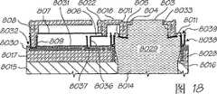
Figure 18 shows the profilograph of the single nozzle that is used for ink-jet that uses in the present invention that is in dormant state;
Figure 19 shows the profilograph of the nozzle of Figure 18 in the initial activation stage;
The nozzle that Figure 20 shows Figure 18 is at the profilograph in after a while actuating stage;
Figure 21 shows the three-dimensional partial, longitudinal cross-sectional of the nozzle of Figure 18, and this nozzle is under the actuating state shown in Figure 20;
Figure 22 shows the three-dimensional vertical section of the nozzle of Figure 18, has wherein omitted China ink;
Figure 23 shows the profilograph of the nozzle of Figure 22;
Figure 24 shows the three-dimensional partial, longitudinal cross-sectional of the nozzle of Figure 18, and this nozzle is under the actuating state shown in Figure 19;
Figure 25 shows the vertical view of the nozzle of Figure 18;
Figure 26 shows the vertical view of the nozzle of Figure 18, has wherein removed control arm and removable nozzle for the purpose of clear;
Figure 27 shows the three-dimensional longitudinal section of the part of a print head chip, the spray nozzle device of the type shown in integrated Figure 18 on this print head chip;
Figure 28 shows a schematic diagram, the figure shows the CMOS that the printer with Fig. 4 uses and drives and controll block;
Figure 29 shows a schematic diagram, the relation in the CMOS piece that the figure shows at Figure 28 between nozzle rows and the point shift register;
Figure 30 shows a more detailed schematic diagram, the figure shows a cell and and the point shift register of Figure 29 and the relation between the nozzle rows;
Figure 31 shows a circuit diagram, the figure shows the logical relation of the single nozzle of the printer that is used for Fig. 4.
The specific embodiment
Shown in Fig. 4-16, the present invention is presented as adesktop PRN device 2, can be in the scope of 60 ppm pages per minutes (ppm) image of flying print photographic quality.Should be appreciated that in the detailed description and claim below, will point to the page or leaf of printing with overall process coloured image (non-some color) all about the reference of print speed and ppm, and at least 80% image has covered this page or leaf.Like this, relatively will print requirement with all of existing PRN device based on this.
To should be readily appreciated that by the following detailed description the size ofPRN device 2 becomes with weight construction: the family expenses or the office that allow this equipment to be placed on a standard are easily used in the table environment, have occupied minimum desk-top space simultaneously.
As briefly showing among Fig. 1, when using,PRN device 2 be arranged to from external source the file printout of---forexample computer system 102---to medium, paper for example.In this regard,PRN device 2 comprises the device that permission is electrically connected betweenequipment 2 and computer system---its mode will be described afterwards---to receive the data of having been handled by computer system 102.In a kind of mode,external computer system 102 is programmed to carry out a plurality of steps that relate to mimeograph documents, comprising: receive file (step 103), deposit in buffer (step 104) and rasterisation (step 106) and then with its compression (step 108) to be transferred toPRN device 2.
Receive image according to thePRN device 2 of an embodiment of the invention from multilayer page formatouter computer 102, that be compression, wherein be arranged on controlelectronic equipment 72 cache images (step 110) in thePRN device 2, expanded images (step 112) is used for further processing then.The continuous tone layer (contone layer) of expansion carries out colour combination (step 114), is compounded on the continuous tone layer that colour combination crosses (step 116) from the black layer of spread step then.Can also apply a coded data (step 118) to form extra play, this layer makes with the naked eye invisible basically infrared China ink print (if needs).Black layer, continuous tone layer and the infrared layer crossed through colour combination combine (step 120) to form a page or leaf that is fed to printhead, are used for printing (step 122).
In this concrete device, the print data for the treatment of associated with the file is divided into high-resolution two-value mask layer that is used for text and line art and the intermediate resolution continuous tone coloured image layer that is used for image and backcolor.Alternatively, can be used for the middle high-resolution continuous tone texture layer that the text (texturingtext) and the line art of veining---have the color data that comes from image or monochromatic color---by increase supported for color text.Print structure by these continuous tones being expressed as abstract " image " and " texture " layer---it can be described as view data or monochromatic data---with these continuous tone vague generalization.Those skilled in the art understands this technology with the data delamination, and wherein these layers are based on the content of following the basic model of mixing grating amount (MRC) pattern.Be similar to the MRC basic model, print structure produces compromise under the certain situation of data overstriking.Particularly, in a form, all processes that clearly embody to trade off that overlap (are conflicted with solving in (collision resolution) and are reduced to 3 layers of representation.
As mentioned above, data with compression, the form of multilayer page-images is sent toPRN device 2, this image is a pretreatment image, preliminary treatment is carried out by themain computer system 102 based on software.Then,PRN device 2 uses main these data of hardware based system handles, and this is shown in further detail in Fig. 2.
In case the data of receiving,distributor 230 is converted to special representation at hardware with data from proprietary representation, and guarantees that these data are sent to correct hardware device, follows any restriction and requirement to these equipment transmissiondatas simultaneously.Distributor 230 is assigned in a plurality ofpipelines 232 suitable one with data converted.Pipeline is mutually the same, and provide decompression basically, convergent-divergent and some complex functionality, to produce the printable some output of a cover.
Eachpipeline 232 comprises abuffer 234 that receives data.Continuoustone decompression machine 236 decompress(ion) color continuous tone faces, and mask decompression machine decompress(ion) monotone (text) layer.Consider that the page will print to the size of the medium on it,continuous tone scaler 240 andmask scaler 242 be the continuous tone face and the mask face of convergent-divergent decompress(ion) respectively.
The continuous tone face of convergent-divergent carries out colour combination bycolour combination device 244 then.In a mode, used random dispersion point colour combination.Different with point (or amplitude modulation) colour combination in groups, spaced point (or frequency modulation) colour combination produces high spatial frequency (being image detail), almost reach the limiting value of point resolution, simultaneously when by eyes when the space is integrated, also can on the panchromatic degree of depth, reproduce low spatial frequency.Carefully design a colour combination matrix at random, relatively can not cause inappropriate low frequency patterns during with tiling demonstration on image.Thereby, typically, its size needed minimum dimension (under 257 shading value ranks, being 16 * 16 * 8 for example) when supporting specific shading value rank.
Then, the face that colour combination is crossed mode with pointwise in asynthesizer 246 is synthesized, so that the point data that is suitable for printing to be provided.These data are transferred in data allocations and thedrive electronics 248, thiselectronic equipment 248 arrivessuitable nozzle actuators 250 with data allocations again then, this nozzle actuators 250 causes China ink to spray fromsuitable nozzle 252 at reasonable time subsequently, and its ejection mode will be explained hereinafter in more detail.
Such as will be appreciated, being used to of inPRN device 2, being adopted the member of handling print image depend on the representation of data to a great extent.In this regard,PRN device 2 can adopt other software and/or hardware component, more handling inPRN device 2, thereby reduces dependence to computer system 102.Alternatively,PRN device 2 can adopt less software and/or hardware component, carrying out less processing, thereby, before data are sent toPRN device 2, depend oncomputer system 102 more and handle image.
Under all situations, carry out the parts that above-mentioned required by task wants and all be arranged in the controlelectronic equipment 72 ofPRN device 2, and Fig. 3 provides the block diagram of this electronic equipment embodiment of expression.
In this was provided with,hardware pipeline 232 was implemented in the small-sized office home office print engine chip (SoPEC).As shown in the figure, a SoPEC device comprises 3 different subsystems: a central processing unit (CPU) subsystem 301, dynamic random access memory (DRAM) subsystem 302 and a print engine pipeline (PEP) subsystem 303.
Cpu subsystem 301 comprises aCPU 30, its control and dispose all aspects of other system.It provides support generally, and with all elements of cooperation andisochronous printing equipment 2, this will be described later.It also controls the low speed communication (it will be described below) to the QA chip.Cpu subsystem 301 also comprises the ancillary equipment of various aiding CPUs, for example general input-output unit (GPIO, it comprises motor control), interruption control module (ICU), LSS main controller and general timer.Serial communication piece (SCB) on cpu subsystem provides USB1.1 interface at full speed to main frame, and provides inner SoPEC interface (ISI) to other SoPEC device (not shown).
DRAM subsystem 302 receives instruction from the piece in CPU, serial communication piece (SCB) and the PEP subsystem.DRAM subsystem 302, especially DRAM interface unit (DIU) are decided each instruction and are determined which instruction should store among the DRAM.DIU can store DRAM based on the parameter ruling that configures into fully to allow all requests.DIU has also hidden the detailed execution information of DRAM, for example quantity of page size, memory bank and refresh rate.
Print engine pipeline (PEP) subsystem 303 from DRAM receive compress page and they are converted to the two-value point that is used for given print wire, this print wire is used for a print head interface that directly is communicated with printhead (PHI).The phase I of page or leaf expansion pipeline is continuous tone decoding unit (CDU), harmless two value decoders (LBD) and also has tag encoder (TE) when needed.Continuous tone (the being generally CMYK) layer of CDU expansion JPEG compression, the two-value layer (being generally K) of LBD expansion compression, and whenPRN device 2 has the webpage function, TE is to the webpage mark of being useful on subsequent conversion encode (being generally IR or K China ink).From the output of phase I one group buffer memory: continuous tone cell fifo (CFU), some cell fifo (SFU) and label FIFO unit (TFU).CFU and SFU buffer memory are applied among the DRAM.
Second stage is halftoning synthesis unit (HCU), and it carries out colour combination and position mark and two-value are put laminatedly to become on the two-value colour combination layer that is obtained the continuous tone layer.
According to the employed printhead of SoPEC, can carry out a plurality of synthetic options.Nearly the two-value data of 6 passages produced in this stage, yet not all passage all can be present on the printhead.For example, printhead may be CMY, and is pushed into K in the CMY passage and omission IR.Alternatively, if IR China ink unavailable (or based on test purpose), then arbitrary coded markings can be printed with K.
In the phase III, the mode that dormancy nozzle compensator (DNC) spreads by color redundancy and the peripherad point tolerance of dormancy nozzle data compensates the dormancy nozzle in the printhead.
The two-value 6 access points data that obtained (be generally CMYK, infrared, fixation) be buffered also and write one group of line buffer memory that is stored among the DRAM by a dotted line r/w cell (DWU).
At last, point data is read back from DRAM, and passes to print head interface by a some FIFO.Point FIFO receives data with system clock frequency (pclk) from row loading unit (LLU), and simultaneously, print head interface (PHI) is taken data away and delivered to printhead with 2/3 times speed of system clock frequency from FIFO.
In a preferred form, the size of DRAM is 2.5Mbyte, and wherein approximately 2Mbyte can be used for page compression storage data.Page compression is contained in two or more districts band, and wherein a plurality of districts band is stored in the memory.In case PEP subsystem 303 has consumed the page or leaf of district's band and has been used for printing, and then can download new district's band.New district's band can be used for current page or following one page.
By district's band mode, can before having downloaded complete page compression, just begin to print a page or leaf, but must be noted that assurance always for printing provides data, the buffer memory situation that supply falls short of demand not so can occur.
USB 1.1 devices that embed receive the page data that compress and from the control instruction of host PC, and are convenient to transfer of data and arrive DRAM (perhaps another SoPEC device in a plurality of SoPEC system is as mentioned below).
A plurality of SoPEC devices can be used in the optional embodiment, and can realize different functions according to specific application.For example, in some cases, the SoPEC device can be used for its airborne DRAM simply, and another SoPEC device is used to realize above-mentioned various decompress(ion)s and format function.This can reduce the buffer memory possibility that supply falls short of demand, and this situation betides when just carrying out the printing of this page and in time not receiving remaining data before printer is useful on a page or leaf receiving the data.Increasing that an other SoPEC device that is used for its memory buffer performance doubled can the data in buffer amount, even do not utilize any other performance of another chip.
Each SoPEC system all can have several quality assurances (QA) devices, thereby guarantees the quality of printing mechanism, the quality of China ink supply thereby these quality assurance devices are designed to be fitted to each other, and---print-head nozzle can not damage in print procedure and the quality of software---guarantees that printhead and mechanism can be not impaired.
Usually relevant information that, each is printed SoPEC and all has corresponding PRN device QA, and it stores and the PRN device feature---for example maximum printing speed---.Print cartridge also can include a black QA chip, and it stores ink tank information---for example remaining China ink amount.Printhead also has a QA chip, is configured to as a ROM (being effective as an EEPROM), and it stores the peculiar information of printhead, for example dormancy nozzle map and printhead feature.CPU in the SoPEC device is alternatively from the QA chip, and---it is used as the EEPROM of a serial effectively---is written into working procedure and encodes.At last, the operation of the CPU in a SoPEC device logic QA chip (i.e. software QA chip).
Usually, the physique of all QA chips is identical in the system, has only the content in the flash memory to differ from one another.
Each SoPEC device all has two LSS system bus, and it can carry out system's evaluation with the communication of QA device and calculate with the China ink amount.Each bus can be used many QA devices, and these QA device positions in system are unrestricted, exception be to print the QA device should be positioned on the different LSS buses with black QA device.
In use, logic QA and the communication of black QA device are to determine remaining China ink.Coming from replying with reference to printing the QA device of black QA device judges.Come from the affirmation itself of printing the QA device and identify, thereby increase an extra evaluation rank indirectly for coming from replying of black QA device by logic QA device.
The data of transmitting between---but not printhead QA---at the QA chip are identified by data signature.In preferred embodiment, HMAC-SHA1 identifies and is used for data that RSA identifies and is used for program coding, though also can instead use other scheme.
Be appreciated that thereby the SoPEC device controls and carry out the most basic data processing task to the integrated operation ofPRN device 2, and synchronously and the operation ofcontrol PRN device 2 each parts, so that the print media easy operating.At the remainder of specification, term controlelectronic equipment 72 will be used to refer to SoPEC device and any other electronic equipment, and they use to control the operation of thisPRN device 2 inPRN device 2.
Fig. 4-16 has drawn an inkjet printing device 2, and it comprises amain body 3; Amedium input module 4 that keeps and support the print media that is used to print; Andmedium output precision 5 of after printing, collecting print media by PRNdevice.Main body 3 is arranged to holdprint engine 70 andrelevant power supply 15 and controlelectronic equipment 72, and paper operating means, this paper operating means effect is: print media was transmitted frommedium input module 4print engine 70---print media is printed here, and arrived thatmedium output precision 5---print media is collected here.This structure provides compact PRN device, and it can be advantageously used in family or working environment, to print multiple image from monochromatic text to the full color photograph image.
With reference to figure 4-12, the structure ofmain body 3 is formed by aupper frame unit 7, and this upper frame unit is configured as and is contained on the underframe unit 6.Upper andlower frame unit base portion 8, a rear portion 9 and an opening 10 together, has held acover 11 on opening 10.Opening 10 provides to the inlet of inner chamber 12, and this inner chamber has heldprint engine 70 and relevant member.
Shown in Fig. 5 and 7, the rear portion 9 of main body 3 is limited by the rear surface of underframe unit 6 and upper frame unit 7.A power supply unit 15 has formed the part at rear portion 9 and has been configured as and has been matched with the recess that is arranged in the underframe unit 6, to power to PRN device 2.Power supply unit 15 fixedly is contained in the recess that forms in underframe unit 6, yet, also can imagine power supply unit 15 can be rechargeable type, can store the electric energy that is fed to PRN device 2, and unit 15 can be pulled down from frame unit 6 when needed and be used for changing like this.An electric-connected socket 16 is arranged on the lead (not shown) that is used in the power supply unit 15 by suitable and is connected to external power source.In underframe unit 6, also formed data gang socket 17, and PRN device 2 the is connected to external source device of---for example computer system 102---be provided, with as above-mentioned mode data and order to PRN device 2 are provided.Data gang socket 17 is the form of standard ethernet and USB device receptacle, and it makes PRN device 2 be connected to terminal 102 or terminal on the net therefrom to receive data and order.This information also can be by PRN device 2 wirelessly by using WIFI card 18 and/or bluetooth card 19 to receive, and these cards are set in place under the cover plate on the rear surface of upper frame unit 7 20.In in these are provided with each, all data that receive are transferred to the SoPEC device of PRN device 2 from socket 17 and card 18,19, are used for handling as above-mentioned mode.
Shown in Fig. 4,6,8 and 11, thecover 11 ofmain body 3 comprises alid 21 that is hinged to underframe unit 6.Lid 21 has curvedupper surface 22 andfront surface 23 and two end faces 24 at angle is arranged, and the shape ofend face 24 cooperates with the top edge of upper frame unit 7.Lid 21 is connected withunderframe unit 6 pivots along the lower limb of thefront surface 23 that the angle is arranged.This pivot connection allows to cover 21 and pivots forward to provide to the inlet of the inner chamber 12 ofmain body 3.
There is thefront surface 23 at angle to have therecess 25 that is formed onwherein.Recess 25 holdsuser interface section 26, and thisunit 26 makes it possible to carry out communication between user and PRN device 2.User interface section 26 is LCD touch-screens, and it transmits information and allow option on the user by selecting display screen directly toPRN device 2 input information to the user.The information type thatuser interface section 26 can be input to PRN device to the information type and the user of user's demonstration can change, yet, usually can relate to the state, the needs that are stored in the China ink in thePRN device 2 and correct plug paper etc., and relate to the information of filling black program again.Use touch-screen as the user interface advantageous particularly, because the information that shows can become specific language by programming, overcome the needs that mark independently or text are provided onPRN device 2 thus, this mark or text can be at the national regulationizations of using this PRN device.Yet, should be appreciated thatuser interface section 26 can be different forms, for example traditional button etc., it allows the user to exchange withPRN device 2.
The front surface that the angle is arranged 23 oflid 21 also is provided withvisual detector unit 27, and it provides the visual indication of printer modes for the user.Visual detector unit 27 extends alonglid 21 surface, and is the form of elongated pipe or panel 28, and it is fromlight source 29 emission light.Color and/or the luminous intensity sent fromvisual detector unit 27 can be controlled by this way: provide the instant indication of the state ofPRN device 2 to need not with reference touser interface section 26 for the user.
Figure 17 a and 17b show the structure of visual detector unit 27.As shown in the figure, unit 27 comprises light source 29 and elongated face plate 28.Light source is three forms that are arranged on the light emitting diode (LED) 30 on the printed circuit board (PCB) (PCB) 31.LED 30 is red, green and blue LED, and it allows the light of wide spectrum to send from panel 28.Yet, should be appreciated that and also can use a LED or other color LED to finish same function.PCB 31 can be the same PCB that comprises the control electronic equipment 72 that is used for PRN device 2, or comprises the independently PCB of suitable electronic equipment, with operation LED 30 under the control of control electronic equipment 72.Elongated face plate 28 is by allowing light to make from LED 30 along its length transmission and from the material of the surface emitting of panel.Panel 28 can be the form of hollow tube, and it is placed on the LED 30 to collect the light that therefrom sends.The inner surface of pipe can cover with film, and this film makes a part of light pass through from panel 28 along length reflection and a part of light of panel 28, has illuminated panel 28 thus, and this can easily be seen from the outer surface of panel 28 by the user.
During use, can control eachLED 30, to send the light of the state of representingPRN device 2 from panel 28.For example, be in standby mode, can excite blue LED, thereby panel 28 send blue light in order to indicate user's PRN device.In print procedure, can excite green LED with transmitting green light from panel 28, and when having problems, for example paperboard or printer are made mistakes, and can excite red LED to send ruddiness from panel 28.In addition, in order to produce decorative effect, each LED can be excited in various combinations, with the light of the various colors of emission in broad spectrum.Because light sends on large tracts of land, rather than as only send light on a point source under the situation that single LED is set in PRN device, the user is easier to by the state that visually perceives printer and is careful printer when needed.This system has carried out the critical function that guarantees effective workplace, and the PRN device with aesthetic joyful sense is provided.
For the print media that is used to print toPRN device 2 supplies,medium input module 4 extends from the rear portion 9 of PRN device 2.Medium input module 4 comprises thatdish portion 32 and medium makebaffle plate 33, and they have formed together and have been used to hold one or more surface that is used for theprint media 34 printed by PRN device 2.Medium input module 4 in the vertical directions extend frommain body 3, and become such angle: in use, each ofprint media 34 supported with vertical orientation bymedium input module 4, and pulls printer into by downward path, as shown in figure 16, the back will more go through.
Can clearlyer see that from Figure 11 thedish portion 32 ofmedium input module 4 is integrally formed withupper frame unit 7, the rear surface ofdish portion 32 forms the part at the rear portion 9 ofmain body 3 thus.The general formation ofdish portion 32 held the container ofprint media 34, and comprises the workingface 35 of placingmedium 34 and at the dielectric support face 36 of one end, thisdielectric support face 36 is suitable for admitting the edge of medium so that medium 34 is remained on verticalposition.Dish portion 32 also comprises thesidewall PRN device 2.
As clearer illustrating among Figure 16,dielectric support face 36 is arranged to the obtuse angle with the workingface 35 ofdish portion 32, is used for printing to assist aprint media 34 to be sent toprint engine 70 from dish portion 32.Working face 35 hasjoint dummy roll 39 thereon, assists aprint media 34 to be sent to print engine fromdish portion 32 to be used for printing to have an effect with a mechanism for picking 60.What place alongdielectric support face 36 intervals is thebar 40 of a plurality of protuberances, and they extend and be supported on the leading edge of the medium 34 on thesurface 36 from dielectric support face 36.The leading edge that bar 40 is used for allowingmedium 34 along the surface ofbar 40 in the effect lower slider of mechanism for picking 60, so that medium 34 is from the transmission of dish portion 32.Contiguous mechanism for picking 60 is provided withpad 41 so that a rubbing surface to be provided on the surface ofbar 40, thereby is convenient to separate that medium 10 of topmost when time on the workingface 35 of many dielectric support in dish portion 32.Pad 41 can be rubber, felt or cork section bar material.
An edge sliding part is suitable for being installed on the workingface 35 ofdish portion 32 by thehook element 43 of an one.One has therecess 44 of groove to be arranged on the workingface 35 to hold the spacer (not shown) of sliding part 42.This device allows slidingpart 42 to move throughsurface 35print media 34 to hold variable-width in a controlled manner.The height ofedge sliding part 42extension dish portions 32 and be provided withwall portion 45, thiswall portion 45 stretches out from the workingface 35 ofdish portion 32, to abut against the lateral edges of print media 34.This device has guaranteed thatprint media 34 anddish portion 32 align suitably to guarantee the controlled delivery of each Zhang Jiezhi to printengine 70.
As shown in figure 11, thesidewall dish portion 32 is provided with thelocation lug 46 on inner surface, is connected to dishportion 32 to guarantee dielectric support baffle plate 33.In this regard, dielectricsupport baffle plate 33 comprises a pair ofjagged tab 47 that extends from the end, and it has heldlug 46 thus, thus dielectricsupport baffle plate 33 is fixed to like that the upper end ofdish portion 32 shown in prominent 1.With this device, dielectricsupport baffle plate 33 can pivot around the end ofdish portion 32, thereby baffleplate 33 is movable to expanding location is loaded intomedium input module 4 with support print media 34 (as shown in Figure 4), perhaps move to retrieving position and be used for packing or loading, wherein dielectricsupport baffle plate 33 is contained in the top (not shown) ofdish portion 32.
The end of dielectricsupport baffle plate 33 extend throughdish portions 32 is with theprint media 34 of bearing length greater than the length of dish portion 32.This device has guaranteed thatprint media 34 remains on a basic vertical position, as shown in Figure 8.In this regard, the surface of dielectricsupport baffle plate 33 is provided with a plurality of uniformly-spacedwing members 48 of extending along the surface longitudinal of baffle plate 33.Eachwing members 48 is extended identical amount from the surface of dielectricsupport baffle plate 35, produced a surface flat for print media thus, and the working face of itself anddish portion 32 is continuous.The inner surface that it is contemplated that dielectricsupport baffle plate 33 also can be the surface of continuous molding, is formed with suitable groove in its marginal zone, packs to fold up when dielectricsupport baffle plate 33 or holds thesidewall dish portion 32 when transportingPRN device 2.
The medium of having printed is collected bymedium output precision 5, and as shown in Figure 4, it is positioned at the base portion ofmain body 3, in the front portion of PRN device 2.Medium output precision 5 comprisesdisk casing 50 and two extensile output panels---top output panel 51 andbottom output panel 52, and two dishes all do not remain in thedisk casing 50 when being in extended position.
Shown in Figure 10 and 11,disk casing 50 is integrally formed withunderframe unit 6, and extends from the rear portion, surpasses the front portion ofPRN device 2 at theedge.Disk casing 50 has upper surface 53 and two sidewalls 54,55 that extend from upper surface 53 downwards.The leading edge of upper surface 53 is open and have therecess 56 that is formed on wherein, so that can enter the upper andlower output panel disk casing 50.
Before the use,medium output precision 5 is in retracted mode shown in Figure 4.When the user caughtstop part 58 and extendsbottom output panel 52,medium output precision 5 entered operating position, as shown in figure 12.This action causes wholemedium output precision 5 to extend to capture from thePRN device 2 interior print media that eject from disk casing 50.After coming out frommain body 3, in case touchbottom output panel 52stop parts 58, the leading edge of print media just is captured.The elongation ofmedium output precision 5 depends on the size of the medium of being printed.For example, if print media has as shown in figure 12 size, the medium of A4 size for example,print media assembly 5 need extend fully to capture and to keep print media so.
As shown in figure 10, as previously mentioned,lid 21 that can be bypivotal cover 11 forward is near the inner chamber 12 of main body 3.The paper operating mechanism that inner chamber 12 holdsprint engine 70 and is forms such as mechanism for picking 60 and paper advance mechanism.
As noted earlier, the purpose of mechanism for picking 60 is from 4 separation of medium input module and transmits individual print media, is used to be sent to theprint engine 70 that is used to print.BecausePRN device 2 can be operated reaching and surpass under the speed of 60ppm, mechanism for picking is configured to adapt to the speed separation that obtains this print speed and to transmit each print media.Thus, mechanism for picking 60 comprises pick-uproller 61, and it is arranged on from the end of thearm 62 that picks up body 63 extensions.Pick up body 63 and comprise amotor 64 by controlelectronic equipment 72 controls of PRN device 2.Picking up body 63 is pivotally mounted on theunderframe unit 6 by a carriage 65.With this set, mechanism for picking can move and be loaded by spring around carriage 65, thereby pick-uproller 61 is forced to the workingface 35 ofdish portion 32.
When not havingprint media 34 in thedish portion 32, pick-uproller 61 is forced to contact withdummy roll 39 on the workingface 35 that is arranged on dish portion 32.In order indish portion 32, to load print media, in the medium 34insertion dish portions 32 and contact be arranged oninduction element 66 on the pick-up roller 61.This contact causes mechanism for picking 60 to pivot and away from the workingface 35 ofdish portion 32, and allows print media to be contained between pick-uproller 61 and thedummy roll 39, and wherein the guide edge ofprint media 34 is supported on the dielectric support face 36.This set is shown in Figure 16.
The surface of pick-uproller 61 is provided with grabbing device, and its form can be the coating of rubber coatings or other similar type or be beneficial to the surface treatment that roller is caught a print media 34.When pick-uproller 61 rotates undermotor 64 effects,cause contacting bar 40 slips of that print media of pick-uproller 61 along protuberance, be used to be sent to print engine 70.Owing to thepad 41 of contiguous mechanism for picking 60 on the surface that is arranged onbar 40, outermost that medium separates from other Zhang Jiezhi that are present in dish portion 32.In this regard, arbitrary medium that moves along with that medium of most external will be subjected to frictional force at 41 o'clock slipping over pad, and this frictional force is greater than the frictional force that causes moving, and therefore only outermost that medium is sent to printengine 70.
Be to be understood that, using mechanism for picking 60 is for higher relativelyspeed separating medium 34 and individual medium is sent to print engine is used for printing, thus, the type that is used for carrying out the mechanism for picking 60 of this function can change, and still falls within the scope of the present invention.
Theprint engine assembly 70 that the present invention uses generally comprises two parts:bracket unit 71 and ink cartridge unit 80.With this set,ink cartridge unit 80 is arranged to be contained in thebracket unit 71.
As illustrating by different way among Figure 11, the 13-16,print cartridge Unit 80 have a body that holdsprinthead ic 81, be used for when aprint media 34 by the time print thereon.The body ofink cartridge unit 80 also holds China ink to be handled andstorage container 82, is used for the storage China ink and transmits China ink to printhead ic 81.Printhead ic 81 is printhead ics of page width, and its outside along the body of print cartridge, the zone under China ink processing andstorage container 82 are provided with, and extend the width of the medium of being printed 34.Opposite with traditional PRN device,printhead ic 81 of the present invention is fixed on a position in operation, and does not scan or pass through print media.Thus, print engine of the present invention can obtain than traditional print system a lot of print speed of obtainable height.
Power supply and data-signal provide from the controlelectronic equipment 72 that is positioned on thebracket unit 71, with the operation of control printhead ic 81.Controlelectronic equipment 72 comprises aforesaid SoPEC device, and the data on the periphery of the body of signal by being arranged onink cartridge unit 80 and power connection (not shown) are transferred toink cartridge unit 80 from control electronic equipment 72.In caseink cartridge unit 80 is insertedbracket unit 71, data and power connection cooperate with corresponding data and power connection on being arranged onbracket unit 71, and power supply and the signal be convenient to thus betweenunit
China ink processing and storage container 82 are the form of a plurality of polyethylene film bags, and these various types of China inks of polyethylene film bag separate storage and printing-fluid are used for printing.For example, ink cartridge unit 80 can be provided with six independently polyethylene film containers, and the infrared China ink and the black fixative that are used for storing cyan, reddish violet, yellow and the black ink that is used for panchromatic printing and are used for specific print application are in order to assist the fixing of China ink.Each container 82 is communicated with corresponding inlet fluid, and this inlet is arranged on refilling in the mouth 83 on the periphery of the body that is formed at ink cartridge unit 80.Thus, container 82 can be by making China ink refill distributor 84 and refill mouthfuls 83 and contact and under pressure China ink is transported in the container 82 and refill respectively, as shown in figure 15.As mentioned above, China ink refills distributor 84 can be equipped with the QA chip, and it is read by the corresponding reader on the body that is arranged on ink cartridge unit 80.Related data is sent to the SoPEC device in the control electronic equipment 72 that is arranged on bracket unit 71 then, with the integrality and the quality of the fluid that guarantees to refill.Refill in order to be beneficial to, polyethylene film container 82 is provided with like this: when filling they the time, their expansions to be holding fluid, and when in print procedure China and Mexico/fluid consuming, the container shrinkage depression.
The pipe that the China ink and the printing-fluid that are stored in thecontainer 82 are carried particular fluid by a series of the setting---for example the China ink of particular color or fixative---is sent toprinthead ic 81, and allows fluid to be assigned to the suitable black delivery nozzles that is provided with along the length of printhead ic 81.The general structure that reaches the mode of this effect andink cartridge unit 80 has been described in the applicant's submission case number in the U.S. Patent application of RRA01US to RRA33US, and its disclosure is here introduced for your guidance.Above-mentioned application number marks by its submission case, in case obtain application number, this submission case number will be replaced with corresponding application number.
As mentioned above, theprinthead ic 81 ofink cartridge unit 80 is printhead ics of page width, it is configured to extend the width of printing 22.4cm (8.8 inches), to hold the print media of degree of broadening, the about 21.6cm of this Du Keda that broadens, it equals the width of the print media ofstandard A 4 or U.S.'s letter form.Yet can also imagine, the printhead ic of page width also can manufacture has greater or lesser width, and this depends on the application ofPRN device 2 and the type of employed print media to a great extent.In order to obtain required width,printhead ic 81 can be made by the integrated circuit of one or more adjacent installations, and wherein each integrated circuit has a plurality of black delivery nozzles disposed thereon.
Describe the example that is suitable for a kind of print-head nozzle device of the present invention referring now to Figure 18 to 27, it comprises a nozzle and corresponding actuator.Figure 27 shows one group ofspray nozzle device 801 that is formed on the silicon substrate 8015.Eachspray nozzle device 801 is identical, and still,spray nozzle device 801 in groups is arranged to supply China ink or the fixative with different colours.In this regard, spray nozzle device is embarked on journey and is provided with and setting interlaced with each other, compares with the single file nozzle, and this allows ink dot nearer at interval in print procedure.This set makes it possible to provide the density of aforesaid nozzle.Multirow also allows redundancy (if needs), allows the predetermined mortality of each nozzle thus.
Eachspray nozzle device 801 all is the product of ic manufacturing technology.Particularly,spray nozzle device 801 has been determined a micro electromechanical system (MEMS).
For clear and be convenient to describe, will be referring to figs. 18 to 26 structure and the operations of describing singlespray nozzle device 801.
Silica (or glass) alternativelylayer 8017 is positioned on the substrate 8015.Silicon dioxide layer 8017 has been determined the CMOS dielectric layer.The CMOS top-level metallic has been determined a pair of aluminiumelectrode contact layer 8030 that is arranged on the alignment on the silicon dioxide layer 8017.Silicon wafer chip 8015 andsilicon dioxide layer 8017 are etched to determine that has theblack access road 8014 of circular section (in vertical view) substantially.Thealuminium diffusion barrier 8028 ofCMOS metal 1,CMOS metal 2/3, CMOS metal top layer is positioned in thesilicon dioxide layer 8017 around black access road 8014.Diffusion barrier 8028 is used for suppressing the hydroxyl ion diffusion and passes throughdrive electronics layer 8017.
The passivation layer that issilicon nitride layer 8031 forms is positioned onaluminium shrinkage layer 8030 and the silicon dioxide layer 8017.Each part that is positioned at thepassivation layer 8031 on thecontact layer 8030 has one and is limited to whereinopening 8032 withnear contact layer 8030.
Spraynozzle device 801 comprises anozzle chambers 8029 of being determined by the nozzle ring wall, and it is being in the interior upper end termination of nozzle top 8034 and innerradial nozzle edge 804---it is circular---in vertical view.Chinaink access road 8014 is communicated withnozzle chambers 8029 fluids.In the lower end of nozzle wall, be provided with by amobile edge 8010, it comprises a mobile sealing lip 8040.Annular wall 8038 is around nozzle movably, and comprises astatic sealing lip 8039, when nozzle stops as shown in figure 10, and thesestandstill seal lip 8039 contiguous mobile edges 8010.Formed fluid sealing 8011 owing to be limited in the surface tension of the China ink betweenstandstill seal lip 8039 and the hydrodynamic reciprocating sealing lip 8040.This has stoped China ink from endoluminal leak, provides the lower resistance coupling simultaneously betweenannular wall 8038 andnozzle wall 8033.
As the clearest illustrating among Figure 25, a plurality ofrecess 8035 that radially extend are formed in the top 8034 aroundnozzle edge.Recess 8035 is used for holding owing to China ink overflows the radially China ink stream thatnozzle edge 804 produces.
Leverage also comprises alever arm 8018, and thislever arm 8018 is from the nozzle wall extension and combine a horizontal buttress brace 8022.Lever arm 8018 is attached on a pair ofpassive beam 806, and thispassive beam 806 is formed and be positioned at the either side of spray nozzle device by titanium nitride, and this sees the most clearly in Figure 21 and 26.The other end ofpassive beam 806 is attached to carriage 036.
As Figure 18 and 24 the clearest illustrating,actuation beam 807 is U-shaped basically on vertical view, has determined a current path betweenelectrode 809 and comparative electrode 8041.Eachelectrode contact 809 electric coupling, actuation beam is also mechanically on grappling to the anchor shape part 808.Anchor shape part 808 is configured to the motion in the left side ofrestriction actuation beam 807 to Figure 18 to 20 when nozzle is in mode of operation.
Titanium nitride inactuation beam 807 conducts electricity, but has sufficiently high resistance, when electric current betweenelectrode passive beam 806 of flowing through, so it does not expand.
In use, be in dormant state the equipment filling China ink 8013, it has formedsemilune 803 under capillary influence.Because semilune, China ink remains in thechamber 8029, and it generally will can not leak when not having other physical influence.
As shown in figure 19, in order to penetrate China ink from nozzle, by electric current, this electric current is byactuation beam 807 betweencontact 809 and 8041.Because its resistance, oneself's heating ofbeam 807 causes this beam to expand.The size ofactuation beam 807 and design mean that most of the expansion occurs on the horizontal direction of Figure 18 to 20.Expansion is limited in the left side byanchor shape part 808, thereby theactuation beam 807 ofcontiguous lever arm 8018 is pushed to the right side.
The moving downward of lever arm 8018 (and slight rotation) by frompassive arm 806 tonozzle wall 8033 distance amplify.Moving downward of nozzle wall and top causes increasing pressure in the chamber, causes semilune to be protruded as shown in Figure 19.Notice that the surface tension of China ink means fluid sealing 11 by this motion stretching, but does not allow ink leakage.
As shown in figure 20, in the suitable time, drive current stops andactuation beam 807 cooling and contraction fast.This contraction causes lever arm to return its resting position, and this causes the pressure inchamber 8029 to reduce again.The power of the China ink that protrudes and intrinsic capillary interaction thereof, and the negative pressure that causes of moving upward ofnozzle chambers 8029 semilune that causes protruding attenuates and final fracture and formed anink droplet 802, and thisink droplet 802 continues upwards until the contiguous print media of its contact.
Followink droplet 802 after separatings closely,semilune 803 has formed concave shape shown in Figure 20.Surface tension causes the pressure inchamber 8029 to keep relatively low, 8014 is upwards inhaled by entering the mouth until China ink, and this makes spray nozzle device and China ink turn back to resting position shown in Figure 180.
With reference now to Figure 28-33, is described in the mode ofprinthead ic 81 inner control single-nozzle devices 101.
Figure 28show printhead ic 81 and with the controlelectronic equipment 72 that is arranged onPRN device 2 in the sketch plan that is connected of SoPEC device.As mentioned above,printhead ic 81 comprises anozzle core array 401---thisnozzle core array 401 comprises the logic circuit of repetition so that each nozzle ink jet, and nozzlecontrol logic circuit 402---, and this nozzlecontrol logic circuit 402 produces timing signals so that each nozzle ink jet.Nozzlecontrol logic circuit 402 receives data by connecting from the SoPEC device at a high speed.
Nozzlecontrol logic circuit 402 is configured to send a series of data by aconnection 407 to the nozzle array core and is used for printing, and thisconnection 407 can be the form of electric connection.State aboutnozzle array core 401 is connected 408 passbacks to nozzlecontrol logic circuit 402 with other operation informations by another, and this connection 408 also can be arranged on the electric connection.
The further details ofnozzle array core 401 has been shown in Figure 29 and 30.In Figure 29, can see thatnozzle array core 401 comprises the array of a nozzle rows 501.This array comprises an injection/selection shift register 502 and reaches 6 color channels that each color channel is by correspondingpoint shift register 503 expressions.
As shown in figure 30, injection/selection shift register 502 comprises that forward path is sprayedshift register 600, backward channel is sprayedshift register 601 and selected shift register 602.Eachpoint shift register 503 comprises an oddpoint shift register 603 and an even number point shift register 604.Odd and even numberpoint shift register 603 at one end is connected with 604, thus data in one direction with clock frequency by oddnumber shift register 603, then on opposite direction by even number shift register 604.Output except last even number point shift register supplies to the input of multiplexer 605.Select by signal (core scanning) in the test process of this output after making of multiplexer.In normal running, the selection of core sweep signal supplies to the some input data Dot[x of the input of other multiplexers 605].This causes being used for the Dot[x of every kind of color] be fed to otherpoint shift register 503 of branch.
Referring now to Figure 30 single row N is described.In the embodiment that illustrates, row N comprises 12 data values, comprises eachodd data value 606 and theeven data value 607 that is used for six point shift registers.Row N also comprises an oddnumber injection value 608 and the evennumber injection value 609 from contra-injection shift register 601 of sprayingshift register 600 from forward, and they supply to multiplexer 610 as input.The output ofmultiplexer 610 is byselective value 611 controls of selecting in the shift register 602.When selective value is 0, the output of odd number injection value, and when selective value is 1, the output of even number injection value.
Each odd and evennumber data value number point latch
Each some latch and relevant data value thereof form a cell, and for example cell 614.In Figure 31, be shown in further detailcell.Point latch 612 is triggers of a D type, and it receives the output ofdata value 606, and this data value is kept by thetrigger 614 of a D type, and trigger 614 has formed odd point shift register 603.Provide (unless the element of being considered is first element in shift register, its input value is Dot[x in the case] value) by the output of the last element in the odd point shift register to the input of the data of trigger 614.In case the negative pulse that provides on Lsyncl is provided, passes to latch 612 with clock frequency from the data oftrigger 614.
The output oflatch 612 is as providing to three tunnel inputs and one of door input of 65.Extremely other inputs with door 615 are Fr signal (from the output of multiplexer 610) and a pulse type signal Pr.The injecting time of nozzle is by pulse type signal Pr control, and can for example prolong to consider because of low-voltage that low supply of electric power produces (can remove in the embodiment that power supply supplies at one).This is the China ink ejection effectively from each nozzle in order to guarantee that quantity is constant relatively when the nozzle ejection.In said embodiment, pulse type signal Pr is identical for each point shift register, and it carries out balance between complexity, cost and performance.Yet at other embodiments, the Pr signal can wholely be supplied with (that is, identical for all nozzles), perhaps can individually be adapted to each cell, even each nozzle.
In case data are loaded intolatch 612, produce the Fr signal and the impulse type Pr signal that spray and supply to and door 615, combine and trigger nozzle ejection ink droplet---comprise thelatch 612 oflogical signal 1 for each.
The signal that is used for each nozzle passage is summarised in following table:
The title direction is described
D inputs to the input point mode signal of shift register position
Q output is from the output point mode signal of shift register position
The rising edge d quilt of clock of SrCIk input shift register input clock signal-at this moment
Catch
The signal that the LsyncL input can be sprayed-need assert to make nozzle ejection
The imported signal of Pr-need assert to make nozzle ejection
As shown in figure 31, injection signal Fr process on diagonal so that spraying a kind of color in the prostatitis, is sprayed next color in the row that continue, or the like.This has divided current order equally by its mode with time delay is distributed in 6 row.
The point latch and the latch that have formed various shift registers are static fully in this embodiment, and based on CMOS.The design of latch and structure are well-known for those technical staff in IC project and design field, therefore no longer describe in this article.
For thePRN device 2 that can print with about 60ppm, the speed of nozzle can reach 20kHz, even higher speed is arranged.In this nozzle velocity scope, the quantity of the China ink that is sprayed bywhole printhead 81 is at least 5,000 ten thousand per seconds.Yet,, can carry out with at least 1 hundred million per second, preferably at least 3 hundred million per seconds, the more preferably printing of the speed of at least 10 hundred million per seconds along with nozzle quantity increases so that more speed and high-quality more to be provided.Therefore, in order to cooperate the printing with these speed, controlelectronic equipment 72 must be able to determine whether nozzle sprays ink droplet with the speed that is equal to.In this regard, in some cases, the control electronic equipment must can determine that whether nozzle sprays ink droplet with the speed of at least 5,000 ten thousand measurement point per seconds.This can be increased at least 1 hundred million measurement point per second or at least 3 hundred million measurement point per seconds, and at least 10 hundred million measurement point per seconds in many cases, is used for more speed, higher-quality print application.
For color printer 100 of the present invention, above-mentioned nozzle quantity scope and the nozzle velocity print speed that is arranged on theprint head chip 81 causes 50cm at least2The area print speed of per second, and, under more speed, cause 100cm at least according to print speed2Per second, preferred 200cm at least2Per second, more preferably 500cm at least2The area print speed of per second.This set provides a kind of like this PRN device 100: its can be under the speed that can't obtain with conventional printing apparatus before this area of print media.
As mentioned above, the said nozzle device is formed in theprinthead ic 81 ofink cartridge unit 80, and thisink cartridge unit 80 has formed the part of print engine.Ink cartridge unit 80 depends on the data and the power supply that transmit from the controlelectronic equipment 72 ofbracket unit 71 and plays a role, and also depends onbracket unit 71 andprinthead ic 81 is arranged on print position and print media was transmittedprinthead ic 81 is used for printing.
In this regard,bracket unit 71 has formed the second portion ofprint engine 70, and remains in the inner chamber 12 ofmain body 3 by the carriage (not shown) that is arranged on the upper andlower frame unit 7,6.In this position, shown in Figure 13-16,bracket unit 71 can receive data from external data source byjoint component 73, and wherein thisjoint component 73 is electrically connected withdata gang socket 17 on the rear portion 9 that is arranged on main body 3.Joint component 73 is a flexible printed circuit board (PCB) preferably, be positioned as be arranged onbracket unit 71 on corresponding joint align.Similarly, power supply is fed tobracket unit 71 by thepower supply contact 74 that extends to inner chamber 12 from power-supply unit 15.Bracket unit 71 is provided with suitable joint component (not shown), and it has connectedpower supply contact 74 to send tobracket unit 71.
As the clearer demonstration of Figure 14,bracket unit 71 is configured as holdsink cartridge unit 80, thereby when being combined together, two unit have formedprint engine assembly 70 as shown in figure 13.In this was provided with, the transmission betweenunit printhead ic 81 controlled with aforementioned manner thus.
The body ofbracket unit 71 comprises: a CD-ROM drive motor 75; A drivenroller 76 and a nip rolls 77 are used for paper was transmittedprint engine 70; Ahead maintenance unit 78 is used toprinthead ic 81 that capping and other forms of maintenance are provided; And controlelectronic equipment 72, it comprises the SoPEC device of the integrated operation that is used to controlPRN device 2.
CD-ROM drive motor 75 is the brushless DC motors with standard of bi-directional capability.CD-ROM drive motor 75 and drivenroller 76 gear drives engagement are providing actuation movement to drivenroller 76, thereby control is by the transmission of the print media of printhead ic 81.The speed of the drivenroller 76 that is driven bymotor 75 transmittedprinthead 81 to guarantee paper with the speed of expectation by 72 controls of control electronic equipment, and this speed reaches usually and surpasses 60ppm.Drivenroller 76 engages with nip rolls 77, androller printhead ic 81.
As shown in figure 16, the body ofbracket unit 71 has aninlet 67 that is arranged onprinthead ic 81 upstreams, contiguous mechanism for picking 60.Inlet 67 holds the leading edge of the print media that is transmitted by mechanism for picking 60, and comprises that assistance is with the leading edge guiding drivenroller 76 of print media and the induction element 69 of nip rolls 77.
Anoutlet 68 is arranged in the body ofbracket unit 71, is in the downstream ofprinthead ic 81, is used for print media from path that printengine 70 comes out to provide one.After being printed byprinthead ic 81, the leading edge of print media comes out fromprint engine 70 under the effect of drivenroller 76 and nip rolls 77.Paper delivering mechanism 85contiguous outlets 68 are provided with to catch the paper of having printed, are used to be sent tomedium output precision 5.
Theidle pulley 87 ofpaper delivering mechanism 85 cooperates withoutlet roller 86 to catch print media and to send it to medium output precision 5.Idle pulley 87 is flexibly connected to cover 21 inner surface and be arranged to and contacts with the loop member rotation that axle alongoutlet roller 86 is provided with.As shown in figure 13,idle pulley 87 is pocket-wheel 91 forms, and it rotates on the surface of loop member 89, and is captured in medium therebetween, is sent tomedium output precision 5 from the medium of printing under the effect of outlet roller 86.That medium that this set assists control to print after printing shifts out fromprint engine 70.
Separate withprint engine 70 with the paper delivering mechanism of describing 85 though should be appreciated that diagram, it is contemplated that the paper delivering mechanism also can become one with print engine 70.In addition, have pocket-wheel 91, also can use for those skilled in the art the significantly control roll of other types, and still fall within the scope of the present invention thoughpaper delivering mechanism 85 is shown.
In described embodiment,print engine 70 is arranged in the inner chamber 12 ofmain body 3, between mechanism for picking 60 and paper delivering mechanism 85.This set allows one frommedium input module 4, byprint engine 70 and enter the simple medium transmission path ofmedium output precision 5.
As shown in figure 16, in order to simplify the path of medium byPRN device 2,print engine 70 is arranged in the inner chamber 12 ofmain body 3 angularly.The angled setting ofprint engine 70causes printhead ic 81 to be provided with angularly, angled print zone is provided thus, and this assists provides one to be used for medium arrivesmedium output precisions 5 through print zones frommedium input module 4 shallow path.Print medium path this simplification and shallow allows the medium of thickening degree and type---promptly until about 300gsm paper---, and printed byPRN device 2, this variable media processes ability does not have in traditional desktop PRN device usually.This set has reduced the possibility that print media gets clogged along its path and needs lasting monitoring and correct and repair or change in some cases under mediumcontact printhead ic 81 situations.
The above-mentioned feature ofPRN device 2 makes it possible to provide to print the colored 1600dpi image of high-quality overall process near the speed of 60ppm, and this image has covered 80% the page at least.These features have produced present commercial also impossible high speed, high-quality printer in conjunction with the size and the footprint of thePRN device 2 of above-mentioned minimizing.
For example,PRN device 2 can be constructed with about 300 millimeters integral width, about 165 millimeters whole height and about 170 millimeters overall depth.Yet, also other sizes can be arranged according to the application of printer.
Thus, it is contemplated that ZhuanPei PRN device 2 has minimum overall volume fully, that is, the actual volume summation that is occupied by the parts ofPRN device 2---comprisesmain body 3,medium input module 4 andmedium output precision 5---and is approximately 14,000cm3(its medium output precision and medium input module launch).It is contemplated that the present invention can wire up and occupy 3000cm3To 30,000cm3Volume.Thus, this causes the printing speed printed under 60ppm and the ratio of printer size (volume) to be at least 0.002ppm/cm3When PRN device can be printed with higher rate, promptly be higher than 60ppm, to print until the above-mentioned duplex of 500ppm, the ratio of printing speed and printer size is at least 0.005ppm/cm3, preferably be approximately 0.01ppm/cm at least3, more preferably be approximately 0.02ppm/cm at least3Be possible.
It is molded that in addition, the parts of printer 100 comprise housing 101,head unit 102,source tray assembly 103,base unit 112, and its a plurality of parts major parts can be by lightweight materials---for example plastics---.Thus, along with the size of above-mentioned minimizing, the weight of printer 100 also can reduce.For example, in a preferred form, printer 100 can have prints 1.5kg to 4.6kg, the weight of 1.8-2.3kg preferably approximately.Thus, under the printing speed of above-mentioned possible color printer 100---initial with about 30ppm-60ppm, the ratio of printing speed and printed weight is that about 0.5ppm/kg is possible.Make the parts of printer 100 even under different situations, use heavier material, the ratio of printing speed and printer weight is 1.0ppm/kg at least, and increase along with printing speed, preferably be at least about 2ppm/kg, more preferably be at least about 5ppm/kg.It is significant improvement that the ratio of this printing speed and printed weight is compared with the existing printer apparatus that has the overall process colour print of 80% page-images coverage rate in generation available on the market at least.
Be to be understood that,PRN device 2 of the present invention provides the desktop printer equipment that can produce the overall process coloured image that is at least 80% page coverage with the speed of about 60 pages of per minutes, and this technology is relevant with off-line, large volume, special PRN device usually.PRN device of the present invention has the similar even littler size of conventional desktop printer, and conventional printer can not be operated under speed of the present invention and print quality.
Though the present invention is explained with reference to example embodiment of the present invention, multiple change is significantly for those skilled in the art and can be easy to obtain, and do not deviate from the scope and spirit of the present invention.In addition, the scope of appended claim is not limited to the description carried out here, but claim should be done wide in range explanation.
Claims (56)
1. PRN device comprises:
Body, this body has:
Be used to support the medium input module of print media;
Be used to collect the medium output precision of print media; And
Has the print engine that is used for the printhead of print image on described dielectric surface;
Wherein said printhead is page width printing head and can be pulled down from described print engine by the user.
2. printer as claimed in claim 1, wherein said printhead are arranged on the print cartridge and described print cartridge can be pulled down from described print engine.
3. printer as claimed in claim 2, wherein said print cartridge are arranged to store the printing-fluid that one or more are used to print.
4. printer as claimed in claim 1, wherein this printer is a desktop printer, and described medium input module is provided with first inclination angle, and described print engine is arranged to: described printhead is in second inclination angle, and described second inclination angle is greater than described first inclination angle.
5. desktop printer as claimed in claim 4, wherein said first inclination angle is between 90 degree and 160 degree.
6. desktop printer as claimed in claim 5, wherein said first inclination angle is between 110 degree and 130 degree.
7. printer as claimed in claim 1, wherein said printhead have at least 10,000 black delivery nozzles disposed thereon.
8. printer as claimed in claim 7, wherein said printhead have at least 20,000 black delivery nozzles disposed thereon.
9. printer as claimed in claim 8, wherein said printhead have at least 50,000 black delivery nozzles disposed thereon.
10. printer as claimed in claim 1, wherein said print engine also comprises the upward control system of the described printhead of control of operation, and this printhead has a plurality of ink nozzles disposed thereon, be used for each ink droplet jet to dielectric surface, thereby in use, control system determines that nozzle is whether with the speed ejection ink droplet of per second 5,000 ten thousand measurement points at least.
11. printer as claimed in claim 10, wherein said control system determine that nozzle is whether with the speed ejection ink droplet of per second 100,000,000 measurement points at least.
12. printer as claimed in claim 11, wherein said control system determine that nozzle is whether with the speed ejection ink droplet of per second 300,000,000 measurement points at least.
13. printer as claimed in claim 12, wherein said control system determine that nozzle is whether with the speed ejection ink droplet of per second 1,000,000,000 measurement points at least.
14. printer as claimed in claim 1, wherein said print engine also comprises the upward control system of control printhead of operation, and this printhead has a plurality of ink nozzles disposed thereon, be used for each ink droplet jet to dielectric surface, thereby in use, print speed is controlled so that the print speed that is at least 0.5ppm/kg and the ratio of printer weight to be provided.
16. printer as claimed in claim 14, wherein print speed is controlled so that the print speed that is at least 1ppm/kg and the ratio of printer weight to be provided.
17. printer as claimed in claim 15, wherein print speed is controlled so that the print speed that is at least 2ppm/kg and the ratio of printer weight to be provided.
18. printer as claimed in claim 17, wherein print speed is controlled so that the print speed that is at least 5ppm/kg and the ratio of printer weight to be provided.
19. printer as claimed in claim 1, wherein said print engine also comprises the control system of the print speed of controlling printhead, and this printhead has a plurality of ink nozzles disposed thereon, be used for each ink droplet jet to dielectric surface, thereby in use, print speed is controlled to provide and is at least 0.002ppm/cm3Print speed and the ratio of printer volume.
20. printer as claimed in claim 19, wherein print speed is controlled to provide and is at least 0.005ppm/cm3Print speed and the ratio of printer volume.
21. printer as claimed in claim 20, wherein print speed is controlled to provide and is at least 0.01ppm/cm3Print speed and the ratio of printer volume.
22. printer as claimed in claim 21, wherein print speed is controlled to provide and is at least 0.02ppm/cm3Print speed and the ratio of printer volume.
23. printer as claimed in claim 1, wherein said print engine also comprises the control system of the print speed of controlling printhead, and this printhead has a plurality of ink nozzles disposed thereon, be used for each ink droplet jet to dielectric surface, thereby in use, print speed is controlled to provide and is at least 50cm2The area print speed of/sec.
24. printer as claimed in claim 23, wherein print speed is controlled to provide and is at least 100cm2The area print speed of/sec.
25. printer as claimed in claim 24, wherein print speed is controlled to provide and is at least 200cm2The area print speed of/sec.
26. printer as claimed in claim 25, wherein print speed is controlled to provide and is at least 500cm2The area print speed of/sec.
27. printer as claimed in claim 1, wherein said medium input module is the dielectric disc that is suitable for receiving one or more print media.
28. printer as claimed in claim 27, wherein said medium is a paper.
29. printer as claimed in claim 27, wherein said dielectric disc tilts along the direction of approximate vertical.
30. printer as claimed in claim 1, wherein said medium output precision comprise one or more dielectric disc that are used to receive and collect by the medium after the described printhead prints.
31. printer as claimed in claim 30, wherein said one or more dielectric disc can be stretched out to hold variable-sized print media from described body.
32. printer as claimed in claim 1, wherein said print engine comprises carriage, and this carriage is fixedly installed in described body and is suitable for receiving described print cartridge and print cartridge is supported on print position.
33. printer as claimed in claim 32, wherein said carriage comprises the control system of whole operations of controlling printer.
34. printer as claimed in claim 33, wherein said control system comprise at least one SoPEC device.
35. printer as claimed in claim 34, wherein said carriage comprises media transport system, and this media transport system is transferred to described medium output system from described medium input module through printhead with medium.
Be used for the medium inlet that receiver media enters print engine 36. printer as claimed in claim 35, wherein said carriage have, described medium inlet is positioned at the upstream of described printhead, near the medium input module.
Be used for transmitting the media outlet of print media from described print engine 37. printer as claimed in claim 36, wherein said carriage have, described media outlet is positioned at the downstream of described printhead, near the medium output precision.
38. printer as claimed in claim 37, wherein said media transport system comprises driven roller and nip rolls, and their actings in conjunction are with transmission medium.
39. printer as claimed in claim 38, wherein said media transport system comprise the medium transmission motor that is used to drive described driven roller.
40. printer as claimed in claim 39, wherein said medium transmission motor is a brushless DC motor.
41. printer as claimed in claim 40, wherein said medium transmission motor is controlled by described control system, and this control system is controlled the operation of described media transport system.
42. printer as claimed in claim 41, wherein said carriage comprises the head maintenance element.
43. printer as claimed in claim 42, wherein said head maintenance element has the capping face that is suitable for the described printhead of capping.
44. printer as claimed in claim 43, wherein said head maintenance element can move to closure position from non-closure position.
45. printer as claimed in claim 44, wherein said closure position are the contacted positions of peripheral part of described capping face and printhead, form sealing thus around described printhead.
46. printer as claimed in claim 45, the medium transmission motor that moves through under described control system control of wherein said head maintenance element provides.
47. printer as claimed in claim 46, wherein said medium is fed to described medium inlet by the medium picking up system from described medium input module.
48. printer as claimed in claim 47, wherein said medium picking up system is installed to described body, and comprises pick-up roller, and the medium that is used for being contained in the described medium input module is sent to described medium inlet.
49. printer as claimed in claim 48, wherein said medium picking up system have the motor that picks up that drives described pick-up roller.
50. printer as claimed in claim 49, the wherein said motor that picks up be by the control of the control system of carriage, with control medium to the print engine supply so that the speed of printing.
51. printer as claimed in claim 50, wherein said print media is sent to described medium output precision by medium transferring mechanism from described media outlet.
52. printer as claimed in claim 51, wherein said medium transferring mechanism comprise outlet roller and idle running element, this medium transferring mechanism receives print media and described medium is sent to described medium output precision.
53. printer as claimed in claim 52, wherein said idle running element are the idle pulleys that one or more and described outlet roller rotation contacts.
54. printer as claimed in claim 52, wherein said idle running element are the dummy rolls that contacts with described outlet roller rotation.
55. as claim 53 or 54 described printers, wherein said outlet roller is driven by the transmission of the medium under the control of the control system of described carriage motor.
56. printer as claimed in claim 55, wherein said medium transferring mechanism is installed to described body, the media outlet of contiguous described carriage.
57. printer as claimed in claim 56, wherein said medium transferring mechanism is installed to described carriage, contiguous described media outlet.
Applications Claiming Priority (2)
| Application Number | Priority Date | Filing Date | Title |
|---|---|---|---|
| US10/760,254US7448734B2 (en) | 2004-01-21 | 2004-01-21 | Inkjet printer cartridge with pagewidth printhead |
| US10/760,254 | 2004-01-21 |
Publications (2)
| Publication Number | Publication Date |
|---|---|
| CN1906037Atrue CN1906037A (en) | 2007-01-31 |
| CN100586715C CN100586715C (en) | 2010-02-03 |
Family
ID=34749937
Family Applications (6)
| Application Number | Title | Priority Date | Filing Date |
|---|---|---|---|
| CN2008101851388AExpired - Fee RelatedCN101450549B (en) | 2004-01-21 | 2004-12-20 | Refill unit for filling ink storage of printer assemble |
| CNB2004800407756AExpired - Fee RelatedCN100457465C (en) | 2004-01-21 | 2004-12-20 | Ink cartridge unit with negative pressure ink reservoir |
| CNB2004800408284AExpired - Fee RelatedCN100482475C (en) | 2004-01-21 | 2004-12-20 | Network inkjet printer unit with multiple media input trays |
| CN200480040776AExpired - Fee RelatedCN100586715C (en) | 2004-01-21 | 2004-12-20 | High Speed Digital Printing Equipment |
| CNB2004800407794AExpired - Fee RelatedCN100548691C (en) | 2004-01-21 | 2004-12-20 | Ink jet printing apparatus with high speed print engine |
| CNA2004800408180APendingCN1918895A (en) | 2004-01-21 | 2004-12-20 | Combination printer and image reader in l-shaped configuration |
Family Applications Before (3)
| Application Number | Title | Priority Date | Filing Date |
|---|---|---|---|
| CN2008101851388AExpired - Fee RelatedCN101450549B (en) | 2004-01-21 | 2004-12-20 | Refill unit for filling ink storage of printer assemble |
| CNB2004800407756AExpired - Fee RelatedCN100457465C (en) | 2004-01-21 | 2004-12-20 | Ink cartridge unit with negative pressure ink reservoir |
| CNB2004800408284AExpired - Fee RelatedCN100482475C (en) | 2004-01-21 | 2004-12-20 | Network inkjet printer unit with multiple media input trays |
Family Applications After (2)
| Application Number | Title | Priority Date | Filing Date |
|---|---|---|---|
| CNB2004800407794AExpired - Fee RelatedCN100548691C (en) | 2004-01-21 | 2004-12-20 | Ink jet printing apparatus with high speed print engine |
| CNA2004800408180APendingCN1918895A (en) | 2004-01-21 | 2004-12-20 | Combination printer and image reader in l-shaped configuration |
Country Status (10)
| Country | Link |
|---|---|
| US (155) | US7448734B2 (en) |
| EP (6) | EP1706274B1 (en) |
| JP (16) | JP2007518602A (en) |
| KR (11) | KR20080108569A (en) |
| CN (6) | CN101450549B (en) |
| AT (1) | ATE510696T1 (en) |
| AU (8) | AU2004314469B2 (en) |
| CA (5) | CA2550790C (en) |
| SG (21) | SG149840A1 (en) |
| WO (6) | WO2005071937A1 (en) |
Cited By (2)
| Publication number | Priority date | Publication date | Assignee | Title |
|---|---|---|---|---|
| CN102857108A (en)* | 2011-07-01 | 2013-01-02 | 佳能株式会社 | Power supply apparatus and printing apparatus |
| CN104044373A (en)* | 2014-06-20 | 2014-09-17 | 张晓玲 | Printer with automatic alarming function |
Families Citing this family (304)
| Publication number | Priority date | Publication date | Assignee | Title |
|---|---|---|---|---|
| US6738096B1 (en)* | 1998-07-10 | 2004-05-18 | Silverbrook Research Pty Ltd | Low-cost disposable camera including print media carrying indication of postage paid |
| US6647270B1 (en)* | 1999-09-10 | 2003-11-11 | Richard B. Himmelstein | Vehicletalk |
| US6526658B1 (en)* | 2000-05-23 | 2003-03-04 | Silverbrook Research Pty Ltd | Method of manufacture of an ink jet printhead having a moving nozzle with an externally arranged actuator |
| JP4380962B2 (en) | 2000-05-24 | 2009-12-09 | シルバーブルック リサーチ ピーティワイ リミテッド | Inkjet printhead manufacturing method |
| AUPS048502A0 (en) | 2002-02-13 | 2002-03-07 | Silverbrook Research Pty. Ltd. | Methods and systems (ap44) |
| AR049674A1 (en)* | 2003-08-08 | 2006-08-30 | Seiko Epson Corp | LIQUID CONTAINER CONTAINER TO SUPPLY A LIQUID SUCH CONSUMPTION APPLIANCE |
| US7249838B2 (en)* | 2004-01-21 | 2007-07-31 | Silverbrook Research Pty Ltd | Self threading wallpaper printer |
| US7469989B2 (en)* | 2004-01-21 | 2008-12-30 | Silverbrook Research Pty Ltd | Printhead chip having longitudinal ink supply channels interrupted by transverse bridges |
| US7156511B2 (en)* | 2004-01-21 | 2007-01-02 | Silverbrook Research Pty Ltd | Inkjet printer cartridge with integral maintenance station |
| US20050157000A1 (en)* | 2004-01-21 | 2005-07-21 | Silverbrook Research Pty Ltd | Inkjet printer cradle with end data and power contacts |
| US7360868B2 (en)* | 2004-01-21 | 2008-04-22 | Silverbrook Research Pty Ltd | Inkjet printer cartridge with infrared ink delivery capabilities |
| US7367647B2 (en)* | 2004-01-21 | 2008-05-06 | Silverbrook Research Pty Ltd | Pagewidth inkjet printer cartridge with ink delivery member |
| US20050157125A1 (en)* | 2004-01-21 | 2005-07-21 | Silverbrook Research Pty Ltd | Inkjet printer cartridge with integral shield |
| US7367650B2 (en) | 2004-01-21 | 2008-05-06 | Silverbrook Research Pty Ltd | Printhead chip having low aspect ratio ink supply channels |
| US7731327B2 (en)* | 2004-01-21 | 2010-06-08 | Silverbrook Research Pty Ltd | Desktop printer with cartridge incorporating printhead integrated circuit |
| US7328985B2 (en) | 2004-01-21 | 2008-02-12 | Silverbrook Research Pty Ltd | Inkjet printer cartridge refill dispenser with security mechanism |
| US7097291B2 (en) | 2004-01-21 | 2006-08-29 | Silverbrook Research Pty Ltd | Inkjet printer cartridge with ink refill port having multiple ink couplings |
| US7448734B2 (en) | 2004-01-21 | 2008-11-11 | Silverbrook Research Pty Ltd | Inkjet printer cartridge with pagewidth printhead |
| US7524016B2 (en)* | 2004-01-21 | 2009-04-28 | Silverbrook Research Pty Ltd | Cartridge unit having negatively pressurized ink storage |
| US7441865B2 (en) | 2004-01-21 | 2008-10-28 | Silverbrook Research Pty Ltd | Printhead chip having longitudinal ink supply channels |
| US20050157128A1 (en)* | 2004-01-21 | 2005-07-21 | Silverbrook Research Pty Ltd | Pagewidth inkjet printer cartridge with end electrical connectors |
| US7364263B2 (en)* | 2004-01-21 | 2008-04-29 | Silverbrook Research Pty Ltd | Removable inkjet printer cartridge |
| US7232208B2 (en)* | 2004-01-21 | 2007-06-19 | Silverbrook Research Pty Ltd | Inkjet printer cartridge refill dispenser with plunge action |
| US7374355B2 (en)* | 2004-01-21 | 2008-05-20 | Silverbrook Research Pty Ltd | Inkjet printer cradle for receiving a pagewidth printhead cartridge |
| US7364264B2 (en) | 2004-01-21 | 2008-04-29 | Silverbrook Research Pty Ltd | Inkjet printer cradle with single drive motor performing multiple functions |
| US7083273B2 (en) | 2004-01-21 | 2006-08-01 | Silverbrook Research Pty Ltd | Inkjet printer cartridge with uniform compressed air distribution |
| US7645025B2 (en)* | 2004-01-21 | 2010-01-12 | Silverbrook Research Pty Ltd | Inkjet printer cartridge with two printhead integrated circuits |
| US7303255B2 (en)* | 2004-01-21 | 2007-12-04 | Silverbrook Research Pty Ltd | Inkjet printer cartridge with a compressed air port |
| US7425050B2 (en)* | 2004-01-21 | 2008-09-16 | Silverbrook Research Pty Ltd | Method for facilitating maintenance of an inkjet printer having a pagewidth printhead |
| US7201468B2 (en) | 2004-01-21 | 2007-04-10 | Silverbrook Research Pty Ltd | Inkjet printer cartridge with fixative delivery capabilities |
| US20050157112A1 (en)* | 2004-01-21 | 2005-07-21 | Silverbrook Research Pty Ltd | Inkjet printer cradle with shaped recess for receiving a printer cartridge |
| US7198352B2 (en)* | 2004-01-21 | 2007-04-03 | Kia Silverbrook | Inkjet printer cradle with cartridge stabilizing mechanism |
| US7121655B2 (en)* | 2004-01-21 | 2006-10-17 | Silverbrook Research Pty Ltd | Inkjet printer cartridge refill dispenser |
| JP4581531B2 (en)* | 2004-07-27 | 2010-11-17 | ソニー株式会社 | Paper discharge tray, paper supply / discharge device, image forming device, and information display device |
| KR100612450B1 (en)* | 2004-10-14 | 2006-08-16 | 삼성전자주식회사 | Ink Cartridges for Wide Array Heads |
| CN101128323B (en)* | 2005-01-10 | 2010-05-12 | 西尔弗布鲁克研究有限公司 | Inkjet printhead manufacturing method |
| US7296881B2 (en)* | 2005-01-21 | 2007-11-20 | Hewlett-Packard Development Company, L.P. | Printhead de-priming |
| US7278720B2 (en)* | 2005-01-24 | 2007-10-09 | Hewlett-Packard Develpoment Company, L.P. | Ink cartridge with multiple chambers aligned along an axial length |
| US7372145B2 (en)* | 2005-02-28 | 2008-05-13 | Silverbrook Research Pty Ltd | Bonded assembly having improved adhesive bond strength |
| US7425052B2 (en)* | 2005-02-28 | 2008-09-16 | Silverbrook Research Pty Ltd | Printhead assembly having improved adhesive bond strength |
| US7468284B2 (en)* | 2005-02-28 | 2008-12-23 | Silverbrook Research Pty Ltd | Method of bonding substrates |
| JP4682862B2 (en)* | 2005-03-31 | 2011-05-11 | セイコーエプソン株式会社 | Liquid container and liquid filling method thereof |
| KR100694132B1 (en)* | 2005-06-28 | 2007-03-12 | 삼성전자주식회사 | Ink channel unit of ink cartridge and manufacturing method therefor |
| JP2007069435A (en)* | 2005-09-06 | 2007-03-22 | Brother Ind Ltd | Droplet discharge device |
| KR100813964B1 (en)* | 2005-09-22 | 2008-03-14 | 삼성전자주식회사 | Array type printhead and inkjet image forming apparatus having same |
| US7399057B2 (en)* | 2005-10-11 | 2008-07-15 | Silverbrook Research Pty Ltd | Printhead maintenance station having cylindrical engagement pad |
| AU2006301900B2 (en)* | 2005-10-11 | 2010-05-27 | Memjet Technology Limited | Printhead maintenance assembly comprising maintenance roller and cleaning mechanism |
| US7669958B2 (en)* | 2005-10-11 | 2010-03-02 | Silverbrook Research Pty Ltd | Printhead cartridge comprising integral printhead maintenance station with maintenance roller |
| US7648222B2 (en)* | 2005-10-11 | 2010-01-19 | Silverbrook Research Pty Ltd | Printhead maintenance station comprising maintenance roller and ink removal system |
| US20070104496A1 (en)* | 2005-11-10 | 2007-05-10 | Xerox Corporation | Illuminated output presence indicator |
| US7758038B2 (en)* | 2005-12-05 | 2010-07-20 | Silverbrook Research Pty Ltd | Printer having compact media pick-up device |
| US7448735B2 (en)* | 2005-12-05 | 2008-11-11 | Silverbrook Research Pty Ltd | Ink priming arrangement for inkjet printhead |
| US7455383B2 (en)* | 2005-12-05 | 2008-11-25 | Silverbrook Research Pty Ltd | Printhead maintenance station having maintenance belt with belt-cleaning station |
| US7445311B2 (en)* | 2005-12-05 | 2008-11-04 | Silverbrook Research Pty Ltd | Printhead maintenance station having maintenance belt |
| US7470002B2 (en)* | 2005-12-05 | 2008-12-30 | Silverbrook Research Ptv Ltd | Printer having self-reference mounted printhead |
| US7448739B2 (en)* | 2005-12-05 | 2008-11-11 | Silverbrook Research Pty Ltd | Constant negative pressure head ink supply arrangement for inkjet printhead |
| US7465033B2 (en)* | 2005-12-05 | 2008-12-16 | Silverbrook Research Ptv Ltd | Self-referencing printhead assembly |
| US7681876B2 (en)* | 2005-12-05 | 2010-03-23 | Silverbrook Research Pty Ltd | Printer having disengageably gear driven media pick-up roller |
| US7448724B2 (en)* | 2005-12-05 | 2008-11-11 | Silverbrook Research Pty Ltd | Method of maintaining a printhead using a maintenance belt |
| US7465042B2 (en)* | 2005-12-05 | 2008-12-16 | Silverbrook Research Pty Ltd | Method of priming inkjet printhead |
| US7722161B2 (en)* | 2005-12-05 | 2010-05-25 | Silverbrook Research Pty Ltd | Method of locating printhead on printer |
| US7632032B2 (en)* | 2005-12-05 | 2009-12-15 | Silverbrook Research Pty Ltd | Method of assembling printer media transport arrangement |
| US7735955B2 (en) | 2005-12-05 | 2010-06-15 | Silverbrook Research Pty Ltd | Method of assembling printhead capping mechanism |
| US7475963B2 (en)* | 2005-12-05 | 2009-01-13 | Silverbrook Research Pty Ltd | Printing cartridge having commonly mounted printhead and capper |
| US7452055B2 (en)* | 2005-12-05 | 2008-11-18 | Silverbrook Research Pty Ltd | Printing cartridge having self-referencing printhead |
| JP4681654B2 (en)* | 2006-03-03 | 2011-05-11 | シルバーブルック リサーチ ピーティワイ リミテッド | Inkjet printer |
| CA2619870C (en)* | 2006-03-03 | 2011-11-08 | Silverbrook Research Pty Ltd | Pulse damped fluidic architecture |
| US7721441B2 (en)* | 2006-03-03 | 2010-05-25 | Silverbrook Research Pty Ltd | Method of fabricating a printhead integrated circuit attachment film |
| US7837297B2 (en) | 2006-03-03 | 2010-11-23 | Silverbrook Research Pty Ltd | Printhead with non-priming cavities for pulse damping |
| KR100754212B1 (en)* | 2006-03-25 | 2007-09-03 | 삼성전자주식회사 | Ink sets, ink cartridges and inkjet recording apparatus containing them |
| JP4725394B2 (en)* | 2006-03-31 | 2011-07-13 | 富士フイルム株式会社 | Inkjet recording device |
| US7992961B2 (en)* | 2006-03-31 | 2011-08-09 | Brother Kogyo Kabushiki Kaisha | Ink-jet head |
| US7726791B2 (en)* | 2006-03-31 | 2010-06-01 | Lexmark International, Inc. | Conduit construction using films |
| JP2007290137A (en)* | 2006-04-20 | 2007-11-08 | Seiko Epson Corp | Liquid cartridge and manufacturing method thereof |
| US20080062452A1 (en)* | 2006-09-11 | 2008-03-13 | Silverbrook Research Pty Ltd | PictBridge printer with photo-sized display screen |
| US7663784B2 (en)* | 2006-09-11 | 2010-02-16 | Silverbrook Research Pty Ltd | Method of storing and displaying photos on a digital photo frame |
| US20080062445A1 (en)* | 2006-09-11 | 2008-03-13 | Silverbrook Research Pty Ltd | Method of printing photos from a printer |
| BRPI0718250A2 (en)* | 2006-11-06 | 2014-01-07 | Seiko Epson Corp | CONTAINER FOR LIQUID |
| MX2009004815A (en)* | 2006-11-06 | 2009-08-28 | Seiko Epson Corp | Liquid container, container holder, and liquid consumption device. |
| JP4946751B2 (en)* | 2006-11-06 | 2012-06-06 | セイコーエプソン株式会社 | Container holder, liquid consumption apparatus, and liquid container |
| US7568694B2 (en) | 2006-11-27 | 2009-08-04 | Eastman Kodak Company | Printed medium collector |
| ES2326841T3 (en)* | 2006-12-28 | 2009-10-20 | Seiko Epson Corporation | MEDIA PROCESSING DEVICE. |
| US20080157405A1 (en)* | 2007-01-03 | 2008-07-03 | International Business Machines Corporation | Chip stack with precision alignment, high yield assembly and thermal conductivity |
| USD580972S1 (en)* | 2007-01-10 | 2008-11-18 | Master Ink Co., Ltd. | Ink cartridge |
| USD575331S1 (en)* | 2007-01-10 | 2008-08-19 | Kenneth Yuen | Ink cartridge |
| US7605009B2 (en) | 2007-03-12 | 2009-10-20 | Silverbrook Research Pty Ltd | Method of fabrication MEMS integrated circuits |
| US7758177B2 (en)* | 2007-03-21 | 2010-07-20 | Silverbrook Research Pty Ltd | High flowrate filter for inkjet printhead |
| WO2008113094A1 (en)* | 2007-03-21 | 2008-09-25 | Silverbrook Research Pty Ltd | Fluidically damped printhead |
| JP4962092B2 (en)* | 2007-03-30 | 2012-06-27 | ブラザー工業株式会社 | Image forming apparatus |
| JP4962094B2 (en)* | 2007-03-30 | 2012-06-27 | ブラザー工業株式会社 | Image forming apparatus |
| JP5056163B2 (en)* | 2007-05-25 | 2012-10-24 | ブラザー工業株式会社 | Ink cartridge determination device and determination method |
| US7866795B2 (en)* | 2007-06-15 | 2011-01-11 | Silverbrook Research Pty Ltd | Method of forming connection between electrode and actuator in an inkjet nozzle assembly |
| US7819503B2 (en)* | 2007-06-15 | 2010-10-26 | Silverbrook Research Pty Ltd | Printhead integrated circuit comprising inkjet nozzle assemblies having connector posts |
| US8789905B2 (en) | 2007-07-02 | 2014-07-29 | Seiko Epson Corporation | Liquid discharging apparatus and method of discharging liquid |
| US20090009541A1 (en) | 2007-07-02 | 2009-01-08 | Seiko Epson Corporation | Liquid discharging apparatus and method of discharging liquid |
| JP2009029112A (en)* | 2007-07-02 | 2009-02-12 | Seiko Epson Corp | Liquid ejection apparatus and liquid ejection method |
| US8128210B2 (en)* | 2007-07-20 | 2012-03-06 | Seiko Epson Corporation | Fluid ejecting apparatus and fluid filling method of fluid ejecting apparatus |
| CA2596123A1 (en) | 2007-08-03 | 2009-02-03 | Carlo Fascio | Refillable ink cartridge |
| JP2009051046A (en)* | 2007-08-24 | 2009-03-12 | Canon Inc | Ink jet recording head and bubble removal method |
| US7914132B2 (en)* | 2007-10-16 | 2011-03-29 | Silverbrook Research Pty Ltd | Inkjet printer with selectively isolatable pump |
| EP2237965B1 (en)* | 2008-01-16 | 2012-09-26 | Silverbrook Research Pty. Ltd | Multiple conduit fluid coupling with leakage flow control |
| US20090179967A1 (en)* | 2008-01-16 | 2009-07-16 | Silverbrook Research Pty Ltd | Multiple conduit fluid coupling with leakage flow control |
| US7845778B2 (en)* | 2008-01-16 | 2010-12-07 | Silverbrook Research Pty Ltd | Printer with zero insertion force printhead cartridge |
| US7922279B2 (en)* | 2008-01-16 | 2011-04-12 | Silverbrook Research Pty Ltd | Printhead maintenance facility with ink storage and driven vacuum drainage coupling |
| EP2543514B1 (en)* | 2008-01-16 | 2015-05-06 | Memjet Technology Limited | Printer with zero insertion force printhead cartridge |
| WO2009114893A1 (en)* | 2008-03-17 | 2009-09-24 | Silverbrook Research Pty Ltd | Fabrication of a printhead integrated circuit attachment film by photopatterning |
| US7845755B2 (en)* | 2008-03-17 | 2010-12-07 | Silverbrook Research Pty Ltd | Printhead integrated circuit attachment film having differentiated adhesive layers |
| US20090233050A1 (en)* | 2008-03-17 | 2009-09-17 | Silverbrook Research Pty Ltd | Fabrication of a printhead integrated circuit attachment film by photopatterning |
| JP4692567B2 (en)* | 2008-03-29 | 2011-06-01 | ブラザー工業株式会社 | Image forming apparatus |
| US7815273B2 (en)* | 2008-04-01 | 2010-10-19 | Hewlett-Packard Development Company, L.P. | Fluid ejection device |
| US8858501B2 (en)* | 2008-04-11 | 2014-10-14 | Medtronic Minimed, Inc. | Reservoir barrier layer systems and methods |
| US9295776B2 (en)* | 2008-04-11 | 2016-03-29 | Medtronic Minimed, Inc. | Reservoir plunger head systems and methods |
| US8206353B2 (en)* | 2008-04-11 | 2012-06-26 | Medtronic Minimed, Inc. | Reservoir barrier layer systems and methods |
| US8293338B2 (en)* | 2008-04-15 | 2012-10-23 | Xerox Corporation | Applying a transparent protective coating to marked media in a print engine |
| US8496320B2 (en)* | 2008-05-08 | 2013-07-30 | Hewlett-Packard Development Company, L.P. | Ink cartridge having a staked vent sealing member |
| US8272704B2 (en) | 2008-05-22 | 2012-09-25 | Zipher Limited | Ink containment system and ink level sensing system for an inkjet cartridge |
| US8091993B2 (en)* | 2008-05-22 | 2012-01-10 | Videojet Technologies Inc. | Ink containment system and ink level sensing system for an inkjet cartridge |
| CN102036829B (en)* | 2008-05-23 | 2013-10-30 | 富士胶片株式会社 | Fluid droplet ejection device and method for fluid droplet ejection |
| JP4687745B2 (en)* | 2008-05-23 | 2011-05-25 | 富士ゼロックス株式会社 | Image processing apparatus, image recording system, and program |
| KR101255579B1 (en)* | 2008-05-23 | 2013-04-17 | 후지필름 가부시키가이샤 | Methods and devices for mounting fluid drain modules |
| USD609272S1 (en)* | 2008-07-18 | 2010-02-02 | Videojet Technologies Inc. | Printer module |
| JP4814927B2 (en) | 2008-10-17 | 2011-11-16 | 株式会社沖データ | Sheet deposition apparatus and image forming apparatus |
| US7631864B1 (en)* | 2008-12-17 | 2009-12-15 | Xerox Corporation | Catch tray for document production device |
| US8342391B2 (en)* | 2008-12-18 | 2013-01-01 | Ncr Corporation | Travel kiosk |
| WO2010068963A1 (en)* | 2008-12-19 | 2010-06-24 | Silverbrook Research Pty Ltd | Ink manifold with multiple conduit shut off valve |
| US8025374B2 (en) | 2008-12-19 | 2011-09-27 | Silverbrook Research Pty Ltd | Ink manifold with multiple conduit shut off valve |
| CN102264870B (en)* | 2008-12-23 | 2014-01-08 | 英特卡设备有限公司 | Substance recovery apparatus and method for regulating substance inventory in one or more units |
| KR20100081555A (en)* | 2009-01-06 | 2010-07-15 | 삼성전자주식회사 | Nozzle capping apparatus for ink-jet printer |
| KR20100081867A (en)* | 2009-01-07 | 2010-07-15 | 삼성전자주식회사 | Ink cartridge and ink circulation system |
| US8544992B2 (en)* | 2009-02-27 | 2013-10-01 | Hewlett-Packard Development Company, L.P. | Fluid cartridge for a printing device |
| US20100228090A1 (en)* | 2009-03-06 | 2010-09-09 | Ethicon Endo-Surgery, Inc. | Methods and devices for providing access into a body cavity |
| US20100231673A1 (en)* | 2009-03-12 | 2010-09-16 | Yuhei Chiwata | Image forming method and apparatus |
| USD642610S1 (en)* | 2009-05-05 | 2011-08-02 | Xerox Corporation | Cleaner apparatus for a phase change ink printer |
| EP2432641A4 (en) | 2009-05-17 | 2012-10-10 | Hewlett Packard Development Co | Fluid-ejection printhead die having mixing barrier |
| US8323993B2 (en)* | 2009-07-27 | 2012-12-04 | Zamtec Limited | Method of fabricating inkjet printhead assembly having backside electrical connections |
| JP5466293B2 (en)* | 2009-07-31 | 2014-04-09 | ザムテック・リミテッド | Printing system with fixed printing head and movable vacuum platen |
| US9048802B2 (en) | 2009-08-17 | 2015-06-02 | Skyworks Solutions, Inc. | Radio frequency power amplifier with linearizing predistorter |
| WO2011023629A1 (en)* | 2009-08-27 | 2011-03-03 | Sanofi-Aventis Deutschland Gmbh | Injector device |
| US9474540B2 (en) | 2009-10-08 | 2016-10-25 | Ethicon-Endo-Surgery, Inc. | Laparoscopic device with compound angulation |
| US8388096B2 (en)* | 2009-12-17 | 2013-03-05 | Hewlett-Packard Development Company, L.P. | Detecting and removing fibers |
| JP5458922B2 (en)* | 2010-02-03 | 2014-04-02 | 富士ゼロックス株式会社 | Image processing apparatus and program |
| JP5077381B2 (en)* | 2010-03-29 | 2012-11-21 | ブラザー工業株式会社 | Liquid ejection device |
| US8256876B2 (en)* | 2010-03-31 | 2012-09-04 | Eastman Kodak Company | Ink passageways connecting inlet ports and chambers |
| JP5577827B2 (en)* | 2010-04-28 | 2014-08-27 | ブラザー工業株式会社 | Inkjet recording device |
| US8313179B2 (en) | 2010-04-29 | 2012-11-20 | Hewlett-Packard Development Company, L.P. | Liquid delivery for a printhead |
| EP2567257B1 (en) | 2010-05-06 | 2021-03-24 | Immunolight, Llc. | Adhesive bonding composition and method of use |
| US8562592B2 (en) | 2010-05-07 | 2013-10-22 | Ethicon Endo-Surgery, Inc. | Compound angle laparoscopic methods and devices |
| US9226760B2 (en) | 2010-05-07 | 2016-01-05 | Ethicon Endo-Surgery, Inc. | Laparoscopic devices with flexible actuation mechanisms |
| US8529028B2 (en) | 2010-05-17 | 2013-09-10 | Zamtec Ltd | Fluid distribution system having printhead bypass from container |
| US20110279535A1 (en)* | 2010-05-17 | 2011-11-17 | Silverbrook Research Pty Ltd | Maintenance apparatus having rotatable wiper and transfer rollers for printhead |
| US8460337B2 (en) | 2010-06-09 | 2013-06-11 | Ethicon Endo-Surgery, Inc. | Selectable handle biasing |
| JP5545058B2 (en) | 2010-06-17 | 2014-07-09 | ブラザー工業株式会社 | Image recording device |
| US20110312078A1 (en)* | 2010-06-17 | 2011-12-22 | Geneasys Pty Ltd | Microfluidic device for detecting target nucleic acid sequences in mitochondrial dna |
| US8205965B2 (en)* | 2010-07-20 | 2012-06-26 | Hewlett-Packard Development Company, L.P. | Print bar structure |
| USD648785S1 (en)* | 2010-07-21 | 2011-11-15 | Hong Kong Applied Science And Technology Research Institute Co., Ltd. | Ink cartridge |
| JP5736702B2 (en)* | 2010-09-21 | 2015-06-17 | セイコーエプソン株式会社 | Recording device |
| JP5621495B2 (en)* | 2010-10-14 | 2014-11-12 | セイコーエプソン株式会社 | Printer control apparatus, printing system, printer control method and program |
| RU2560393C2 (en)* | 2010-10-21 | 2015-08-20 | Органово, Инк. | Devices, systems and methods of making fabric |
| US8020850B1 (en)* | 2010-10-29 | 2011-09-20 | Lexmark International, Inc. | Removable input tray assembly having a dual function roller for feeding media and separating media in an image forming device |
| US8235376B2 (en)* | 2010-10-29 | 2012-08-07 | Lexmark International, Inc. | Removable input tray assembly having an integrated roller nip for an image forming device |
| US20120127246A1 (en)* | 2010-11-18 | 2012-05-24 | Chi-Chang Liu | Ink cartridge structure |
| USD665019S1 (en)* | 2010-11-19 | 2012-08-07 | Domino Printing Sciences Plc | Printer service module |
| US8894190B2 (en)* | 2010-11-19 | 2014-11-25 | Domino Printing Sciences Plc | Relating to inkjet printers |
| USD665842S1 (en)* | 2010-11-19 | 2012-08-21 | Domino Printing Sciences Plc | Printer service module |
| JP2012121168A (en)* | 2010-12-06 | 2012-06-28 | Canon Inc | Liquid ejection head, and method of producing the same |
| JP5724398B2 (en)* | 2011-01-14 | 2015-05-27 | セイコーエプソン株式会社 | Container unit and liquid jet system |
| JP5343994B2 (en)* | 2011-03-31 | 2013-11-13 | ブラザー工業株式会社 | Recording device |
| WO2012166439A1 (en)* | 2011-05-27 | 2012-12-06 | Dsa Detection Llc | Multi-dopant permeation tube |
| US20130025125A1 (en)* | 2011-07-27 | 2013-01-31 | Petruchik Dwight J | Method of fabricating a layered ceramic substrate |
| US8897629B1 (en) | 2012-01-27 | 2014-11-25 | Scent Sciences Corporation | Scent delivery apparatus |
| JP6045227B2 (en)* | 2012-07-05 | 2016-12-14 | キヤノン株式会社 | Inkjet recording device |
| US8905528B2 (en)* | 2012-07-24 | 2014-12-09 | Eastman Kodak Company | Ink tank with a compliant wick |
| JP6135073B2 (en) | 2012-09-01 | 2017-05-31 | 株式会社リコー | Image forming apparatus |
| US9421781B2 (en)* | 2012-10-15 | 2016-08-23 | Seiko Epson Corporation | Recording apparatus |
| JP5794221B2 (en)* | 2012-12-19 | 2015-10-14 | コニカミノルタ株式会社 | Image forming apparatus |
| JP2014151976A (en)* | 2013-02-05 | 2014-08-25 | Seiko Epson Corp | Medium transport device and recording apparatus |
| JP5692265B2 (en)* | 2013-03-07 | 2015-04-01 | セイコーエプソン株式会社 | Liquid ejecting apparatus, liquid supply apparatus, and liquid container |
| US8851617B1 (en) | 2013-03-25 | 2014-10-07 | Hewlett-Packard Development Company, L.P. | Provide printing fluid to printhead |
| US10105901B2 (en) | 2013-09-13 | 2018-10-23 | Microjet Technology Co., Ltd. | Rapid prototyping apparatus with page-width array printing module |
| TWI579151B (en)* | 2014-12-19 | 2017-04-21 | 研能科技股份有限公司 | Page width printing rapid prototyping device |
| US9015903B2 (en)* | 2013-09-20 | 2015-04-28 | Hewlett-Packard Development Company, L.P. | Pin connector |
| WO2015047231A1 (en)* | 2013-09-25 | 2015-04-02 | Hewlett-Packard Development Company, L.P. | Printhead assembly with one-piece printhead support |
| JP6221566B2 (en)* | 2013-09-26 | 2017-11-01 | セイコーエプソン株式会社 | Method for regenerating liquid container and liquid container |
| CN105705340B (en) | 2013-11-19 | 2018-06-26 | 马姆杰特科技有限公司 | The method of printing color base oil ink, for its ink group, ink and printing machine |
| GB2520745A (en)* | 2013-11-29 | 2015-06-03 | Ingegneria Ceramica S R L | An improved support bar for a printhead |
| US9420503B2 (en) | 2014-01-21 | 2016-08-16 | Cisco Technology, Inc. | System and method for seamless mobility in a network environment |
| PL3552828T3 (en) | 2014-01-31 | 2021-03-08 | Hewlett-Packard Development Company, L.P. | Ink supplies and methods to prepare ink supplies |
| CN103832080B (en)* | 2014-03-20 | 2015-10-28 | 北京美科艺数码科技发展有限公司 | Assistant print cartridges, ink feeding system and inkjet-printing device |
| JP6361861B2 (en)* | 2014-03-25 | 2018-07-25 | セイコーエプソン株式会社 | Recording device |
| JP6187364B2 (en) | 2014-03-31 | 2017-08-30 | ブラザー工業株式会社 | Printing device |
| CN103862889A (en)* | 2014-04-04 | 2014-06-18 | 晏石英 | Dust-free printing system |
| US9427048B2 (en)* | 2014-06-09 | 2016-08-30 | Nike, Inc. | Polymeric component with injected, embedded ink and apparatus and method for manufacturing same |
| DE102014213874A1 (en)* | 2014-07-16 | 2016-01-21 | Siemens Aktiengesellschaft | Preconcentrator for adsorbing and / or desorbing at least one component of a gas |
| WO2016010543A1 (en) | 2014-07-17 | 2016-01-21 | Hewlett-Packard Development Company, L.P. | Print bar structure |
| USD763140S1 (en)* | 2014-07-25 | 2016-08-09 | Inter-Power Corporation | Billet push rod |
| USD761338S1 (en)* | 2014-07-25 | 2016-07-12 | Inter-Power Corporation | Billet push rod |
| USD763331S1 (en)* | 2014-07-25 | 2016-08-09 | Inter-Power Corporation | Billet push rod |
| US10668727B2 (en) | 2014-07-30 | 2020-06-02 | Hewlett-Packard Development Company, L.P. | Printer cap |
| JP6394185B2 (en)* | 2014-08-28 | 2018-09-26 | セイコーエプソン株式会社 | Printing device |
| US9546292B2 (en) | 2014-11-19 | 2017-01-17 | Memjet Technology Limited | Ink additive combinations for improving printhead lifetime |
| TWI633018B (en)* | 2014-12-19 | 2018-08-21 | 研能科技股份有限公司 | Rapid prototyping device using page-width array printing |
| CN107206806B (en) | 2015-01-29 | 2019-09-17 | 惠普发展公司,有限责任合伙企业 | Method for starting to use printing system and printing system |
| US10377556B2 (en) | 2015-02-04 | 2019-08-13 | S.C. Johnson & Son, Inc. | Retaining apparatus |
| RU2699443C2 (en)* | 2015-05-28 | 2019-09-05 | Сикпа Холдинг Са | Ink reservoir with back pressure system |
| USD763332S1 (en)* | 2015-05-31 | 2016-08-09 | Huai Wu | 3D printhead |
| JP2017056629A (en)* | 2015-09-16 | 2017-03-23 | 船井電機株式会社 | Image formation device |
| WO2017074354A1 (en) | 2015-10-28 | 2017-05-04 | Hewlett-Packard Development Company, L.P. | Printer cartridge with multiple backpressure chambers |
| CN106739525A (en)* | 2015-11-25 | 2017-05-31 | 周利平 | Caritrdge |
| CN106808802A (en)* | 2015-11-28 | 2017-06-09 | 周利军 | The external ink feeding system of environment-protecting intelligent |
| US9969165B2 (en) | 2016-01-08 | 2018-05-15 | Canon Kabushiki Kaisha | Liquid discharge head and liquid discharge apparatus |
| US10022979B2 (en) | 2016-01-08 | 2018-07-17 | Canon Kabushiki Kaisha | Liquid ejection head, liquid ejection apparatus, and manufacturing method |
| JP6987498B2 (en)* | 2016-01-08 | 2022-01-05 | キヤノン株式会社 | Liquid discharge board, liquid discharge head, and liquid discharge device |
| EP3238676B1 (en) | 2016-04-29 | 2019-01-02 | The Procter and Gamble Company | Absorbent core with profiled distribution of absorbent material |
| EP3448687B1 (en) | 2016-04-29 | 2022-06-01 | Hewlett-Packard Development Company, L.P. | Printer door hinge assembly |
| TWI715755B (en)* | 2016-05-02 | 2021-01-11 | 愛爾蘭商滿捷特科技公司 | Monochrome inkjet printhead configured for high-speed printing |
| US10507679B2 (en)* | 2016-05-24 | 2019-12-17 | Electronics For Imaging, Inc. | Replication alignment of components for use in inkjet printing applications |
| US10076902B2 (en) | 2016-05-27 | 2018-09-18 | Canon Kabushiki Kaisha | Print element substrate, liquid ejection head, and printing device |
| JP6821331B2 (en) | 2016-05-30 | 2021-01-27 | キヤノン株式会社 | Recording element substrate, liquid discharge head, and liquid discharge device |
| JP6742825B2 (en)* | 2016-06-06 | 2020-08-19 | キヤノン株式会社 | Control device and control method |
| JP6901246B2 (en)* | 2016-08-03 | 2021-07-14 | 富士通コンポーネント株式会社 | Printer |
| EP3509845A4 (en) | 2016-09-09 | 2020-04-22 | Hewlett-Packard Development Company, L.P. | PRINTING MODULE AND ACCESSORIES COUPLING |
| JP2019531206A (en) | 2016-09-12 | 2019-10-31 | ヒューレット−パッカード デベロップメント カンパニー エル.ピー.Hewlett‐Packard Development Company, L.P. | Printing subassembly |
| EP3509857A4 (en)* | 2016-09-12 | 2020-04-15 | Hewlett-Packard Development Company, L.P. | Apparatus with light sources |
| JP7005232B2 (en) | 2016-09-27 | 2022-01-21 | キヤノン株式会社 | Recording head, element board, and recording device |
| JP2018054949A (en)* | 2016-09-29 | 2018-04-05 | 富士ゼロックス株式会社 | Image formation apparatus |
| JP2018054948A (en)* | 2016-09-29 | 2018-04-05 | 富士ゼロックス株式会社 | Image forming apparatus |
| JP2018054947A (en)* | 2016-09-29 | 2018-04-05 | 富士ゼロックス株式会社 | Image formation apparatus |
| IT201600098327A1 (en)* | 2016-09-30 | 2018-03-30 | Omso Officina Macchine Per Stampa Su Oggetti Spa | Ink jet printing machine for three-dimensional objects, in particular tubular objects |
| JP6891488B2 (en)* | 2016-12-27 | 2021-06-18 | セイコーエプソン株式会社 | Printing equipment |
| TW201838829A (en) | 2017-02-06 | 2018-11-01 | 愛爾蘭商滿捷特科技公司 | Inkjet print head for full color page wide printing |
| CN110573345B (en) | 2017-03-14 | 2021-04-23 | 伊利诺斯工具制品有限公司 | Quick connect assemblies for fluid and electrical connections |
| US10283476B2 (en) | 2017-03-15 | 2019-05-07 | Immunolight, Llc. | Adhesive bonding composition and electronic components prepared from the same |
| CN110546009B (en) | 2017-03-30 | 2021-12-31 | 惠普发展公司,有限责任合伙企业 | Module, image forming apparatus and system for increasing storage capacity of medium |
| JP7125421B2 (en) | 2017-04-13 | 2022-08-24 | メムジェット テクノロジー リミテッド | Low toxicity ink formulation with improved printhead life |
| CN107415477A (en)* | 2017-09-12 | 2017-12-01 | 陆永添 | A kind of high speed weaving ink jet printer with shower nozzle cleaning moisturizing mechanism |
| CN107757131B (en)* | 2017-09-28 | 2019-06-25 | 北京盛通印刷股份有限公司 | A kind of ink storage device of improved cartridge of ink-jet printer |
| WO2019078899A1 (en)* | 2017-10-20 | 2019-04-25 | Hewlett-Packard Development Company, L.P. | Ink cartridge caps |
| CN109693449B (en)* | 2017-10-24 | 2020-09-15 | 精工爱普生株式会社 | Recording device and liquid storage unit |
| JP7026486B2 (en) | 2017-11-07 | 2022-02-28 | エスアイアイ・プリンテック株式会社 | Liquid injection head and liquid injection recorder |
| JP7059591B2 (en)* | 2017-11-28 | 2022-04-26 | セイコーエプソン株式会社 | Liquid sprayer |
| KR102024615B1 (en)* | 2017-12-06 | 2019-09-24 | 세메스 주식회사 | Apparatus for Cleaning Droplet in Inkjet Head and Method for Cleaning Droplet in Inkjet |
| US11639056B2 (en) | 2017-12-15 | 2023-05-02 | Hewlett-Packard Development Company, L.P. | Fluidic ejection controllers with selectively removable ejection boards |
| CN108099412A (en)* | 2017-12-28 | 2018-06-01 | 南宁远卓新能源科技有限公司 | Anti-bubble print cartridge |
| EP3658382B1 (en)* | 2018-01-31 | 2024-11-13 | Hewlett-Packard Development Company, L.P. | Print substance end-of-life predictions |
| CN110126471A (en)* | 2018-02-08 | 2019-08-16 | 亿码(厦门)标识科技有限公司 | Push type ink-supplying ink cartridge |
| JP7005376B2 (en) | 2018-02-15 | 2022-01-21 | キヤノン株式会社 | Device substrate, recording head, and recording device |
| CN111819083B (en)* | 2018-03-08 | 2022-03-29 | 惠普发展公司,有限责任合伙企业 | Attachment, dummy cartridge, method for inserting dummy cartridge into printer |
| US11925932B2 (en) | 2018-04-24 | 2024-03-12 | Hewlett-Packard Development Company, L.P. | Microfluidic devices |
| WO2019209375A1 (en) | 2018-04-24 | 2019-10-31 | Hewlett-Packard Development Company, L.P. | Droplet ejectors to draw fluids through microfluidic networks |
| WO2020018074A1 (en)* | 2018-07-17 | 2020-01-23 | Hewlett-Packard Development Company, L.P. | Droplet ejectors to provide fluids to droplet ejectors |
| KR20190124014A (en)* | 2018-04-25 | 2019-11-04 | 휴렛-팩커드 디벨롭먼트 컴퍼니, 엘.피. | Sensor cleaning for paper feeding system of image forming apparatus |
| US11020966B2 (en)* | 2018-04-27 | 2021-06-01 | Canon Kabushiki Kaisha | Liquid ejection head substrate, method of manufacturing liquid ejection head substrate, and liquid ejection head |
| WO2019211070A1 (en) | 2018-05-03 | 2019-11-07 | Memjet Technology Limited | Inkjet printhead with encapsulant-retaining features |
| US20210147166A1 (en)* | 2018-05-09 | 2021-05-20 | Hewlett-Packard Development Company, L.P. | Print devices |
| WO2020009699A1 (en) | 2018-07-04 | 2020-01-09 | Hewlett-Packard Development Company, L.P. | Liquid delivery system for an inkjet type dispenser |
| ES2931994T3 (en)* | 2018-07-13 | 2023-01-05 | Hewlett Packard Development Co | Hose-fed casing printing fluid supply interconnect |
| EP3820703B1 (en)* | 2018-07-13 | 2024-01-10 | Hewlett-Packard Development Company, L.P. | Print substance reservoirs |
| RU2751584C1 (en)* | 2018-07-13 | 2021-07-15 | Хьюлетт-Паккард Дивелопмент Компани, Л.П. | Device for supplying printing liquid |
| US11535036B2 (en) | 2018-07-13 | 2022-12-27 | Hewlett-Packard Development Company, L.P. | Unattended reservoir refillings |
| US11547993B2 (en) | 2018-07-17 | 2023-01-10 | Hewlett-Packard Development Company, L.P. | Droplet ejectors with target media |
| US20210322970A1 (en)* | 2018-07-17 | 2021-10-21 | Hewlett-Packard Development Company, L.P. | Droplet ejectors to mix fluids |
| TWI657036B (en)* | 2018-07-18 | 2019-04-21 | 信紘科技股份有限公司 | Automatic slot filling docking device |
| US11305540B2 (en) | 2018-07-20 | 2022-04-19 | Hewlett-Packard Development Company, L.P. | Cleaning print head cap |
| US20210237351A1 (en)* | 2018-08-30 | 2021-08-05 | Hewlett-Packard Development Company, L.P. | Syringe bodies |
| WO2020046329A1 (en) | 2018-08-30 | 2020-03-05 | Hewlett-Packard Development Company, L.P. | Valve housing rotation prevention |
| CN112262347B (en) | 2018-08-30 | 2023-11-10 | 惠普发展公司,有限责任合伙企业 | Contacts for printing particle input recesses |
| RU2767283C1 (en)* | 2018-08-30 | 2022-03-17 | Хьюлетт-Паккард Дивелопмент Компани, Л.П. | Syringes with plungers |
| WO2020046311A1 (en) | 2018-08-30 | 2020-03-05 | Hewlett-Packard Development Company, L.P. | Rotatable dispensing nozzles |
| CN108726215A (en)* | 2018-09-07 | 2018-11-02 | 天津光电通信技术有限公司 | A kind of the print media dilatation frame and image forming apparatus of image forming apparatus |
| KR20200052726A (en)* | 2018-11-07 | 2020-05-15 | 휴렛-팩커드 디벨롭먼트 컴퍼니, 엘.피. | Coupler holder based toner locking system |
| WO2020101686A1 (en) | 2018-11-15 | 2020-05-22 | Hewlett-Packard Development Company, L.P. | Print substance gauge authentication |
| USD934341S1 (en) | 2018-12-03 | 2021-10-26 | Hewlett-Packard Development Company, L.P. | Ink cartridge |
| WO2020117217A1 (en)* | 2018-12-04 | 2020-06-11 | Hewlett-Packard Development Company, L.P. | Print device functionalities |
| US11919313B2 (en) | 2018-12-04 | 2024-03-05 | Hewlett-Packard Development Company, L.P. | Print device functionalities |
| CN109671040B (en)* | 2018-12-31 | 2023-05-12 | 珠海智汇网络设备有限公司 | Print picture data processing method, computer device, and computer-readable storage medium |
| US20210165346A1 (en)* | 2019-01-24 | 2021-06-03 | Hewlett-Packard Development Company, L.P. | Refill dispenser for refilling developer cartridge |
| WO2020159517A1 (en) | 2019-01-31 | 2020-08-06 | Hewlett-Packard Development Company, L.P. | Fluidic die with surface condition monitoring |
| CN113412194B (en) | 2019-02-06 | 2023-01-13 | 惠普发展公司,有限责任合伙企业 | Integrated circuit including memory cells |
| US11494481B2 (en)* | 2019-05-10 | 2022-11-08 | Canon Kabushiki Kaisha | Authentication apparatus for authenticating authentication target device |
| CN110077119A (en)* | 2019-05-20 | 2019-08-02 | 黄春燕 | A kind of environment-friendly type ink-feeding device |
| CN113329882B (en)* | 2019-07-08 | 2023-01-06 | 惠普发展公司有限责任合伙企业 | Device for supplying printing material |
| WO2021006880A1 (en) | 2019-07-09 | 2021-01-14 | Hewlett-Packard Development Company, L.P. | Photoconductor having optical tag |
| US11794483B2 (en) | 2019-08-30 | 2023-10-24 | Primera Technology, Inc. | Delivery tray mounting system for food product printer |
| US20220227138A1 (en)* | 2019-09-11 | 2022-07-21 | Hewlett-Packard Development Company, L.P. | Printers with refillable printing fluid reservoirs |
| WO2021054931A1 (en)* | 2019-09-16 | 2021-03-25 | Hewlett-Packard Development Company, L.P. | Circulation paths for fluid dispensing devices |
| WO2021086383A1 (en)* | 2019-10-31 | 2021-05-06 | Hewlett-Packard Development Company, L.P. | Maintenance scheduling |
| WO2021086400A1 (en)* | 2019-11-01 | 2021-05-06 | Hewlett-Packard Development Company, L.P. | Apparatus having electric interconnects |
| JP2021111280A (en)* | 2020-01-15 | 2021-08-02 | キヤノン株式会社 | How to form a mutual authentication pair and authentication device |
| WO2021216063A1 (en)* | 2020-04-22 | 2021-10-28 | Hewlett-Packard Development Company, L.P. | Fluid ejection apparatus |
| US11090938B1 (en)* | 2020-05-15 | 2021-08-17 | Funai Electric Co., Ltd. | Multi-array ejection head and method of use |
| WO2022033814A1 (en) | 2020-08-13 | 2022-02-17 | Memjet Technology Limited | Inkjet printhead having robust encapsulation of wirebonds |
| JP7463918B2 (en)* | 2020-09-03 | 2024-04-09 | セイコーエプソン株式会社 | Liquid injection device |
| US20230398735A1 (en)* | 2020-10-20 | 2023-12-14 | General Electric Company | Printing assemblies and methods for using the same |
| WO2022087044A1 (en) | 2020-10-21 | 2022-04-28 | General Electric Company | Material supply system and method for using the same |
| WO2022093233A1 (en)* | 2020-10-29 | 2022-05-05 | Hewlett-Packard Development Company, L.P. | Tray to hold sheet media for printing |
| US12246540B2 (en) | 2020-11-20 | 2025-03-11 | Hewlett-Packard Development Company, L.P. | Profile governing servicing maintenance of fluidic printhead nozzles |
| JP7635052B2 (en)* | 2021-03-31 | 2025-02-25 | キヤノン株式会社 | Liquid ejection head and manufacturing method thereof |
| WO2022268427A1 (en) | 2021-06-23 | 2022-12-29 | Memjet Technology Limited | Thermal regulation in long inkjet printhead |
| US11529599B1 (en) | 2021-12-13 | 2022-12-20 | Cana Technology, Inc. | Electromechanical valve sequencing for fluid mixture dispensing devices |
| CN115570897B (en)* | 2022-05-21 | 2024-11-19 | 河南印都数码科技有限公司 | Circulation powder shaking device |
| CN115071289A (en)* | 2022-06-30 | 2022-09-20 | 珠海恒盛条码设备有限公司 | Main part and base quick detach formula printer |
| JP2024052286A (en)* | 2022-09-30 | 2024-04-11 | セイコーエプソン株式会社 | Liquid ejection device |
| WO2024193932A1 (en) | 2023-03-23 | 2024-09-26 | Memjet Technology Limited | Inks for improving printhead lifetime |
| CN117262812B (en)* | 2023-11-21 | 2024-02-09 | 南京爱德印刷有限公司 | Special thin dictionary paper Zhang Jiqi folding device |
Family Cites Families (746)
| Publication number | Priority date | Publication date | Assignee | Title |
|---|---|---|---|---|
| US386898A (en)* | 1888-07-31 | Secondary battery | ||
| US270177A (en)* | 1883-01-02 | brooks | ||
| US590669A (en)* | 1897-09-28 | Horse-collar pad | ||
| US485435A (en)* | 1892-11-01 | Combined easy | ||
| US620651A (en)* | 1899-03-07 | Dress-guard for bicycles | ||
| US450148A (en)* | 1891-04-14 | Rotary fan | ||
| US587788A (en)* | 1897-08-10 | Morton | ||
| US10A (en)* | 1836-08-10 | Bariah Swift | Dye-wood and dye-stuff cutting and shaving machine | |
| US86467A (en)* | 1869-02-02 | Egbert w | ||
| US656198A (en)* | 1897-03-10 | 1900-08-21 | James R Maccoll | Lappet-loom. |
| US644355A (en)* | 1898-04-02 | 1900-02-27 | George B Haycock | Fountain-cuspidor. |
| US628912A (en)* | 1898-07-29 | 1899-07-18 | George William Bayley | Acetylene-gas lamp. |
| US654398A (en)* | 1899-04-15 | 1900-07-24 | Ernest Hollings | Guncotton-press. |
| US667584A (en)* | 1900-05-01 | 1901-02-05 | Sterling Arc Lamp Company | Electric-arc lamp. |
| US655976A (en)* | 1900-06-16 | 1900-08-14 | Henry S Jacobs | Bait or other net. |
| US6789191B1 (en) | 1999-05-25 | 2004-09-07 | Silverbrook Research Pty Ltd | Interactive device network registration protocol |
| US1880354A (en) | 1931-07-30 | 1932-10-04 | Herman C Mueller | Fluid gun |
| US3214067A (en) | 1962-09-11 | 1965-10-26 | Thomas R Linington | Fluid dispenser |
| US3270182A (en)* | 1964-03-26 | 1966-08-30 | Hynes Electric Heating Company | High temperature fluid heater |
| GB1051747A (en)* | 1964-08-28 | |||
| US3403679A (en) | 1964-12-11 | 1968-10-01 | Secr Defence Brit | Hypodermic injection apparatus with a secondary capsule-collapsing means |
| US3950761A (en) | 1973-01-04 | 1976-04-13 | Casio Computer Co., Ltd. | Ink pressurizing apparatus for an ink jet recorder |
| US3948259A (en) | 1973-03-09 | 1976-04-06 | Population Research Incorporated | Dispensing instrument |
| US3886938A (en)* | 1973-10-23 | 1975-06-03 | Scala Anthony | Power operated fluid infusion device |
| US3868698A (en)* | 1973-10-24 | 1975-02-25 | Mead Corp | Stimulation control apparatus for an ink jet recorder |
| DE2460573A1 (en) | 1974-12-20 | 1976-07-01 | Siemens Ag | DEVICE FOR INKJET PEN FOR SUPPLYING PIEZOELECTRICALLY OPERATED WRITING NOZZLES WITH WRITING LIQUID |
| US4007465A (en)* | 1975-11-17 | 1977-02-08 | International Business Machines Corporation | System for self-cleaning ink jet head |
| DE2607313C3 (en) | 1976-02-23 | 1979-01-25 | Siemens Ag, 1000 Berlin Und 8000 Muenchen | Protection and cleaning device for writing heads in ink writing devices |
| DE2610518C3 (en) | 1976-03-12 | 1983-04-07 | Siemens AG, 1000 Berlin und 8000 München | Ink reservoirs for ink writing devices |
| US4183031A (en) | 1976-06-07 | 1980-01-08 | Silonics, Inc. | Ink supply system |
| JPS54103351A (en)* | 1978-01-31 | 1979-08-14 | Sharp Corp | Fluid feed mechanism |
| JPS54123950A (en) | 1978-03-17 | 1979-09-26 | Matsushita Electric Ind Co Ltd | Ink jet recorder |
| JPS55158975A (en)* | 1979-05-26 | 1980-12-10 | Ricoh Co Ltd | Ink supplying mechanism of ink jet recording device |
| DE3022128C2 (en)* | 1980-06-10 | 1983-12-08 | Mannesmann AG, 4000 Düsseldorf | Print head for generating print characters using the matrix printing process |
| DE3021913A1 (en) | 1980-06-11 | 1981-12-17 | Siemens AG, 1000 Berlin und 8000 München | PIVOTING INK REFLECTOR FOR THE SCAN HEAD OF AN INK WRITER |
| US4342042A (en) | 1980-12-19 | 1982-07-27 | Pitney Bowes Inc. | Ink supply system for an array of ink jet heads |
| US4329698A (en)* | 1980-12-19 | 1982-05-11 | International Business Machines Corporation | Disposable cartridge for ink drop printer |
| US4333456A (en) | 1981-02-09 | 1982-06-08 | Sterling Drug Inc. | Self-aspirating hypodermic syringe and self-aspirating assembly therefor |
| JPS57159658A (en) | 1981-03-27 | 1982-10-01 | Fujitsu Ltd | Ink jet recording head |
| JPS57201682A (en)* | 1981-06-08 | 1982-12-10 | Canon Inc | Ink cassette |
| US4415101A (en)* | 1982-01-22 | 1983-11-15 | Shapiro Justin J | Incremental liquid dispensing device |
| NZ203203A (en) | 1982-02-16 | 1985-09-13 | Commw Scient Ind Res Org | Controlled release device:gas diffusion limited |
| US4558326A (en)* | 1982-09-07 | 1985-12-10 | Konishiroku Photo Industry Co., Ltd. | Purging system for ink jet recording apparatus |
| US4500148A (en)* | 1983-01-31 | 1985-02-19 | H. King & Associates, Ltd. | Display and storage unit |
| US4594697A (en)* | 1983-05-25 | 1986-06-10 | Pascouet Adrien P | Pneumatically-operated liquid slug projector apparatus |
| US6247803B1 (en)* | 1983-10-13 | 2001-06-19 | Seiko Epson Corporation | Ink jet recording apparatus and method for replenishing ink in the tank cartridge |
| DE3401071A1 (en)* | 1984-01-13 | 1985-07-25 | Siemens AG, 1000 Berlin und 8000 München | Device for refilling ink containers in inking apparatuses |
| JPH0626886B2 (en)* | 1984-01-30 | 1994-04-13 | キヤノン株式会社 | Liquid jet recording device |
| JPH0753450B2 (en)* | 1984-03-31 | 1995-06-07 | キヤノン株式会社 | Liquid jet recording device |
| EP0168592B1 (en)* | 1984-05-29 | 1988-08-03 | Siemens Aktiengesellschaft | Device for reading and/or for printing on record carriers |
| US4580148A (en)* | 1985-02-19 | 1986-04-01 | Xerox Corporation | Thermal ink jet printer with droplet ejection by bubble collapse |
| US5202702A (en)* | 1985-04-08 | 1993-04-13 | Canon Kabushiki Kaisha | Ink jet recording apparatus and a method of cleaning a recording head used in the apparatus |
| US4591869A (en) | 1985-04-12 | 1986-05-27 | Eastman Kodak Company | Ink jet printing apparatus and method providing an induced, clean-air region |
| US4719474A (en) | 1985-07-19 | 1988-01-12 | Rudolf Hell Gmbh | Apparatus for imaging text and graphics on photosensitive material |
| US4594597A (en)* | 1985-08-13 | 1986-06-10 | Sanders Associates, Inc. | Thermal printer |
| US4612010A (en) | 1985-08-14 | 1986-09-16 | Hamacher Edward N | Infiltration pump |
| US4694597A (en)* | 1985-10-15 | 1987-09-22 | Kuei Wen Sheu | Electric perpetual calendar |
| JPS63502573A (en) | 1986-02-25 | 1988-09-29 | ジ−メンス アクチエンゲゼルシヤフト | Method and apparatus for sealing and cleaning ink outlet openings in ink print heads |
| US4832918A (en) | 1986-06-12 | 1989-05-23 | Inpal Co., Ltd. | Rotary ozonizer |
| US4771295B1 (en)* | 1986-07-01 | 1995-08-01 | Hewlett Packard Co | Thermal ink jet pen body construction having improved ink storage and feed capability |
| US4727378A (en)* | 1986-07-11 | 1988-02-23 | Tektronix, Inc. | Method and apparatus for purging an ink jet head |
| US4728969A (en)* | 1986-07-11 | 1988-03-01 | Tektronix, Inc. | Air assisted ink jet head with single compartment ink chamber |
| GB2197751A (en)* | 1986-11-24 | 1988-05-25 | Philips Electronic Associated | Variable shaped spot electron beam pattern generator |
| US5019839A (en)* | 1986-12-25 | 1991-05-28 | Canon Kabushiki Kaisha | Recording apparatus having a movable sheet guide member |
| US4727387A (en) | 1987-06-24 | 1988-02-23 | Blaser Industries, Inc. | Paper-handling mechanism for laser printer |
| DE3855368T2 (en)* | 1987-11-10 | 1997-02-20 | Mita Industrial Co Ltd | Imaging device |
| US4831389A (en)* | 1987-12-21 | 1989-05-16 | Hewlett-Packard Company | Off board ink supply system and process for operating an ink jet printer |
| CH678169A5 (en)* | 1988-03-07 | 1991-08-15 | Rutishauser Data Ag | |
| JPH01231755A (en)* | 1988-03-08 | 1989-09-18 | Fuji Xerox Co Ltd | Device for detecting number of sheet of discharged paper |
| US4971527A (en)* | 1988-03-30 | 1990-11-20 | Videojet Systems International, Inc. | Regulator valve for an ink marking system |
| DE3814720A1 (en)* | 1988-04-30 | 1989-11-09 | Olympia Aeg | METHOD FOR PRODUCING A BASE PLATE WITH INTEGRATED WORKINGS FOR AN INK PRINT HEAD |
| US5182581A (en)* | 1988-07-26 | 1993-01-26 | Canon Kabushiki Kaisha | Ink jet recording unit having an ink tank section containing porous material and a recording head section |
| US5184178A (en) | 1988-09-13 | 1993-02-02 | Canon Kabushiki Kaisha | Image recording apparatus having an interchangeable cartridge |
| JPH02132026A (en) | 1988-10-20 | 1990-05-21 | Ricoh Co Ltd | image forming device |
| US6097407A (en) | 1988-11-09 | 2000-08-01 | Canon Kabushiki Kaisha | Package for ink jet head |
| US4992802A (en) | 1988-12-22 | 1991-02-12 | Hewlett-Packard Company | Method and apparatus for extending the environmental operating range of an ink jet print cartridge |
| JP2683126B2 (en) | 1988-12-28 | 1997-11-26 | キヤノン株式会社 | Ink jet recording device |
| JP2575205B2 (en)* | 1989-01-13 | 1997-01-22 | キヤノン株式会社 | Ink tank |
| US4959667A (en)* | 1989-02-14 | 1990-09-25 | Hewlett-Packard Company | Refillable ink bag |
| US5049898A (en)* | 1989-03-20 | 1991-09-17 | Hewlett-Packard Company | Printhead having memory element |
| US4907019A (en)* | 1989-03-27 | 1990-03-06 | Tektronix, Inc. | Ink jet cartridges and ink cartridge mounting system |
| US5006002A (en) | 1989-04-11 | 1991-04-09 | Clancy Systems International, Inc. | Portable printing apparatus with movable paper feed gate |
| JP2810701B2 (en)* | 1989-05-31 | 1998-10-15 | キヤノン株式会社 | Ink jet recording head and ink jet recording apparatus |
| US4973993A (en) | 1989-07-11 | 1990-11-27 | Hewlett-Packard Company | Ink-quantity and low ink sensing for ink-jet printers |
| US4967207A (en)* | 1989-07-26 | 1990-10-30 | Hewlett-Packard Company | Ink jet printer with self-regulating refilling system |
| US4968998A (en)* | 1989-07-26 | 1990-11-06 | Hewlett-Packard Company | Refillable ink jet print system |
| US4935750A (en) | 1989-08-31 | 1990-06-19 | Xerox Corporation | Sealing means for thermal ink jet printheads |
| US5027134A (en)* | 1989-09-01 | 1991-06-25 | Hewlett-Packard Company | Non-clogging cap and service station for ink-jet printheads |
| JP2771278B2 (en)* | 1989-09-20 | 1998-07-02 | 株式会社日立製作所 | Facsimile machine |
| US4935751A (en)* | 1989-09-21 | 1990-06-19 | Hewlett-Packard Company | Level sensor for ink bag |
| EP0495785B1 (en)* | 1989-10-13 | 1994-12-07 | Eastman Kodak Company | Printer |
| US4985710A (en) | 1989-11-29 | 1991-01-15 | Xerox Corporation | Buttable subunits for pagewidth "Roofshooter" printheads |
| CA2019290A1 (en)* | 1990-01-12 | 1991-07-12 | Bruce Cowger | Pressure-sensitive accumulator for ink-jet pens |
| US4978343A (en)* | 1990-01-16 | 1990-12-18 | Dysarz Edward D | Trap in barrel one handed retractable safety syringe |
| EP0438270B1 (en)* | 1990-01-17 | 1996-01-10 | Canon Kabushiki Kaisha | Liquid jet recording head |
| US5186449A (en)* | 1990-01-23 | 1993-02-16 | Mita Industrial Co., Ltd. | Sheet feeder unit |
| JP2752495B2 (en) | 1990-02-13 | 1998-05-18 | キヤノン株式会社 | Ink jet recording device |
| ES2080246T3 (en) | 1990-02-02 | 1996-02-01 | Canon Kk | PRINTING METHOD AND APPARATUS. |
| DE69122539T2 (en)* | 1990-02-13 | 1997-03-13 | Canon Kk | A cover device and an ink jet recording device using the same |
| GB2242867B (en)* | 1990-02-15 | 1994-04-13 | Canon Kk | Waste ink receiving cartridge and ink recording apparatus using said cartridge |
| US5717444A (en) | 1990-04-11 | 1998-02-10 | Canon Kabushiki Kaisha | Suction recovery device and ink jet recording apparatus using the device |
| GB9010289D0 (en) | 1990-05-08 | 1990-06-27 | Xaar Ltd | Drop-on-demand printing apparatus and method of manufacture |
| US5051761A (en) | 1990-05-09 | 1991-09-24 | Xerox Corporation | Ink jet printer having a paper handling and maintenance station assembly |
| JPH0427556A (en)* | 1990-05-23 | 1992-01-30 | Canon Inc | Ink jet recorder |
| US5469199A (en)* | 1990-08-16 | 1995-11-21 | Hewlett-Packard Company | Wide inkjet printhead |
| JP2713811B2 (en)* | 1990-10-03 | 1998-02-16 | キヤノン株式会社 | Recording medium feeding device and recording device |
| US6249481B1 (en)* | 1991-10-15 | 2001-06-19 | Kabushiki Kaisha Toshiba | Semiconductor memory device |
| US5159348A (en)* | 1990-10-29 | 1992-10-27 | Xerox Corporation | Ink jet printing apparatus |
| US5138332A (en)* | 1990-10-29 | 1992-08-11 | Xerox Corporation | Ink jet printing apparatus |
| JP2752793B2 (en)* | 1990-12-10 | 1998-05-18 | キヤノン株式会社 | Ink jet recording apparatus and ink tank cartridge for the apparatus |
| US5233369A (en)* | 1990-12-27 | 1993-08-03 | Xerox Corporation | Method and apparatus for supplying ink to an ink jet printer |
| DE69224921T2 (en)* | 1991-01-11 | 1998-08-27 | Canon Kk | Ink jet recorder |
| JP2962838B2 (en) | 1991-01-18 | 1999-10-12 | キヤノン株式会社 | Ink jet recording device |
| US6019457A (en)* | 1991-01-30 | 2000-02-01 | Canon Information Systems Research Australia Pty Ltd. | Ink jet print device and print head or print apparatus using the same |
| JP3054208B2 (en)* | 1991-03-01 | 2000-06-19 | 帝人製機株式会社 | Magnetic field measurement device |
| JPH04288261A (en) | 1991-03-18 | 1992-10-13 | Canon Inc | recording device |
| US5624196A (en)* | 1991-04-16 | 1997-04-29 | Hewlett-Packard Company | Method and apparatus for paper control including kickers |
| US5185614A (en)* | 1991-04-17 | 1993-02-09 | Hewlett-Packard Company | Priming apparatus and process for multi-color ink-jet pens |
| US5191382A (en)* | 1991-04-22 | 1993-03-02 | Canon Kabushiki Kaisha | Image forming system |
| JP2955384B2 (en)* | 1991-04-26 | 1999-10-04 | キヤノン株式会社 | Image recording device |
| US5160945A (en) | 1991-05-10 | 1992-11-03 | Xerox Corporation | Pagewidth thermal ink jet printhead |
| US6264314B1 (en) | 1991-05-27 | 2001-07-24 | Seiko Epson Corporation | Ink cartridge for ink jet recording apparatus |
| US5192959A (en) | 1991-06-03 | 1993-03-09 | Xerox Corporation | Alignment of pagewidth bars |
| US5359353A (en) | 1991-06-19 | 1994-10-25 | Hewlett-Packard Company | Spring-bag printer ink cartridge with volume indicator |
| US5963238A (en)* | 1991-06-19 | 1999-10-05 | Hewlett-Packard Company | Intermittent refilling of print cartridge installed in an inkjet printer |
| US5748216A (en)* | 1991-06-19 | 1998-05-05 | Hewlett-Packard Company | Inkjet print cartridge having valve connectable to an external ink reservoir for recharging the print cartridge |
| US5745137A (en)* | 1992-08-12 | 1998-04-28 | Hewlett-Packard Company | Continuous refill of spring bag reservoir in an ink-jet swath printer/plotter |
| US5793387A (en)* | 1991-06-19 | 1998-08-11 | Hewlett-Packard Company | Method and apparatus for ink-jet ink level detection |
| US5187498A (en)* | 1991-07-24 | 1993-02-16 | Xerox Corporation | Ink supply container and system |
| US5155497A (en) | 1991-07-30 | 1992-10-13 | Hewlett-Packard Company | Service station for ink-jet printer |
| JP3012043B2 (en)* | 1991-08-20 | 2000-02-21 | 三田工業株式会社 | Optional equipment |
| JP3351436B2 (en) | 1991-08-21 | 2002-11-25 | セイコーエプソン株式会社 | Two-part adhesive sheet material having pores |
| JPH0584919A (en)* | 1991-09-27 | 1993-04-06 | Seiko Epson Corp | Ink jet head |
| JP3009764B2 (en) | 1991-10-03 | 2000-02-14 | キヤノン株式会社 | Ink jet recording device |
| JP2761685B2 (en)* | 1991-10-17 | 1998-06-04 | 三菱電機株式会社 | Method for manufacturing semiconductor device |
| KR940003112B1 (en)* | 1991-10-25 | 1994-04-13 | 삼성전자 주식회사 | Cassettes used in electrophotographic equipment |
| US5216442A (en)* | 1991-11-14 | 1993-06-01 | Xerox Corporation | Moving platen architecture for an ink jet printer |
| US5222186A (en)* | 1991-12-06 | 1993-06-22 | Globol Gmbh | Electrical apparatus for vaporizing of active substances |
| US5613952A (en) | 1991-12-23 | 1997-03-25 | Syringe Develpoment Partners | Safety syringe |
| US5477963A (en)* | 1992-01-28 | 1995-12-26 | Seiko Epson Corporation | Ink-jet recording apparatus and ink tank cartridge therefor |
| CN1096943C (en) | 1992-02-26 | 2002-12-25 | 佳能株式会社 | Ink jet record method and recorded material thereof |
| DE69325532T2 (en) | 1992-03-09 | 1999-12-02 | Canon K.K., Tokio/Tokyo | Multiple recording device using a monochrome printer |
| US5406320A (en)* | 1992-03-10 | 1995-04-11 | Scitex Digital Printing, Inc. | Ink replenishment assemblies for ink jet printers |
| US5467118A (en) | 1993-12-21 | 1995-11-14 | Hewlett-Packard Company | Ink cartridge for a hard copy printing or plotting apparatus |
| US5396268A (en)* | 1992-03-27 | 1995-03-07 | Scitex Digital Printing, Inc. | Refill apparatus and method |
| DE69309153T2 (en)* | 1992-06-04 | 1997-10-09 | Tektronix Inc | On-demand ink jet print head with improved cleaning performance |
| IT1256844B (en)* | 1992-06-08 | 1995-12-21 | Olivetti & Co Spa | METHOD AND DEVICE FOR THE RECOGNITION OF THE END-INK IN AN INK-JET PRINT HEAD. |
| US5294946A (en)* | 1992-06-08 | 1994-03-15 | Signtech Usa, Ltd. | Ink jet printer |
| US5450112A (en)* | 1992-12-23 | 1995-09-12 | Hewlett-Packard Company | Laminated film for ink reservoir |
| US5754207A (en) | 1992-08-12 | 1998-05-19 | Hewlett-Packard Company | Volume indicating ink reservoir cartridge system |
| US5757390A (en)* | 1992-08-12 | 1998-05-26 | Hewlett-Packard Company | Ink volume sensing and replenishing system |
| JPH06125141A (en)* | 1992-08-25 | 1994-05-06 | Olympus Optical Co Ltd | Semiconductor quantum well optical element |
| US5455609A (en) | 1992-09-30 | 1995-10-03 | Hewlett-Packard Company | Printhead servicing station for printers |
| US5561450A (en) | 1992-09-30 | 1996-10-01 | Pitney Bowes Inc. | Apparatus for mounting an ink jet cartridge on a support therefor |
| US5359356A (en) | 1992-09-30 | 1994-10-25 | Ecklund Joel E | Collapsible jet-ink container assembly and method |
| US5238044A (en)* | 1992-10-20 | 1993-08-24 | Gilley Paul D | Window treatment support device |
| US5221397A (en) | 1992-11-02 | 1993-06-22 | Xerox Corporation | Fabrication of reading or writing bar arrays assembled from subunits |
| US5404158A (en)* | 1992-11-12 | 1995-04-04 | Xerox Corporation | Ink jet printer maintenance system |
| CA2112182C (en) | 1992-12-25 | 2000-06-27 | Masami Ikeda | Detachable ink jet unit and ink jet apparatus |
| US5527871A (en)* | 1992-12-28 | 1996-06-18 | Kabushiki Kaisha Toyota Chuo Kenkyusho | Layered inorganic-organic polymer shaped article thereof and process for producing the same |
| JP3356818B2 (en)* | 1993-03-09 | 2002-12-16 | 富士ゼロックス株式会社 | Ink supply device for inkjet recording device |
| US5365645A (en) | 1993-03-19 | 1994-11-22 | Compaq Computer Corporation | Methods of fabricating a page wide piezoelectric ink jet printhead assembly |
| JPH06317953A (en)* | 1993-04-28 | 1994-11-15 | Canon Inc | Frame structure and image forming device |
| US5825378A (en)* | 1993-04-30 | 1998-10-20 | Hewlett-Packard Company | Calibration of media advancement to avoid banding in a swath printer |
| US5392063A (en)* | 1993-04-30 | 1995-02-21 | Hewlett-Packard Company | Spring cartridge clamp for inkjet printer carriage |
| US6206514B1 (en)* | 1993-06-29 | 2001-03-27 | Canon Kabushiki Kaisha | Ink tank unit, an ink jet cartridge having said ink tank unit and an ink jet apparatus having said ink jet cartridge |
| JPH0728392A (en)* | 1993-07-12 | 1995-01-31 | Omron Corp | Programmable controller |
| DE69426390T2 (en) | 1993-07-31 | 2001-04-12 | Weston Medical Ltd., Stradbroke Eye | NEEDLE-FREE INJECTOR |
| JPH0749463A (en)* | 1993-08-05 | 1995-02-21 | Fuji Xerox Co Ltd | Optical deflector |
| JP3155667B2 (en) | 1993-08-10 | 2001-04-16 | キヤノン株式会社 | Recording device |
| JP3133906B2 (en)* | 1993-08-19 | 2001-02-13 | キヤノン株式会社 | Ink tank cartridge |
| SG72660A1 (en)* | 1993-08-23 | 2000-05-23 | Canon Kk | Exchangeable ink cartridge |
| US5532825A (en)* | 1993-08-30 | 1996-07-02 | Hewlett-Packard Company | Add-on scanner for existing ink jet printer |
| JP3217610B2 (en)* | 1993-09-03 | 2001-10-09 | キヤノン株式会社 | Ink jet recording device and information processing system |
| IT1272050B (en) | 1993-11-10 | 1997-06-11 | Olivetti Canon Ind Spa | PARALLEL PRINTER DEVICE WITH MODULAR STRUCTURE AND RELATED CONSTRUCTION PROCEDURE. |
| US5696546A (en)* | 1993-11-15 | 1997-12-09 | Xerox Corporation | Ink supply cartridge with ink jet printhead having improved fluid seal therebetween |
| JP3219609B2 (en)* | 1993-11-29 | 2001-10-15 | キヤノン株式会社 | Ink refill device and ink refill method |
| US5619239A (en) | 1993-11-29 | 1997-04-08 | Canon Kabushiki Kaisha | Replaceable ink tank |
| US5400573A (en)* | 1993-12-14 | 1995-03-28 | Crystal; Richard G. | Kit and method for opening, refilling and sealing a cartridge |
| JP3298279B2 (en)* | 1993-12-24 | 2002-07-02 | 株式会社村田製作所 | Dielectric resonator device, method of adjusting coupling coefficient thereof, and device for manufacturing the same |
| US5657065A (en)* | 1994-01-03 | 1997-08-12 | Xerox Corporation | Porous medium for ink delivery systems |
| US5369017A (en)* | 1994-02-04 | 1994-11-29 | The Scripps Research Institute | Process for solid phase glycopeptide synthesis |
| US5565900A (en) | 1994-02-04 | 1996-10-15 | Hewlett-Packard Company | Unit print head assembly for ink-jet printing |
| US5682186A (en)* | 1994-03-10 | 1997-10-28 | Hewlett-Packard Company | Protective capping apparatus for an ink-jet pen |
| US5572245A (en) | 1994-03-10 | 1996-11-05 | Hewlett-Packard Company | Protective cover apparatus for an ink-jet pen |
| US5712668A (en)* | 1994-03-25 | 1998-01-27 | Hewlett-Packard Company | Rotary Multi-ridge capping system for inkjet printheads |
| US5574489A (en)* | 1994-03-30 | 1996-11-12 | Hewlett-Packard Company | Ink cartridge system for ink-jet printer |
| US5515663A (en) | 1994-04-06 | 1996-05-14 | Nu-Kote International, Inc. | Method of refilling ink-jet printer cartridges |
| JPH07311058A (en)* | 1994-05-20 | 1995-11-28 | Citizen Watch Co Ltd | Ink cartridge |
| US5640644A (en)* | 1994-06-07 | 1997-06-17 | Konica Corporation | Image forming apparatus having toner replenishment device |
| US5581287A (en) | 1994-06-30 | 1996-12-03 | Jetfill, Inc. | Inkjet printer ink cartridge refilling structure |
| US5572244A (en) | 1994-07-27 | 1996-11-05 | Xerox Corporation | Adhesive-free edge butting for printhead elements |
| AU3241795A (en)* | 1994-08-09 | 1996-03-07 | Encad, Inc. | Printer ink cartridge |
| CA2434525C (en) | 1994-08-24 | 2006-01-03 | Canon Kabushiki Kaisha | Ink container for ink jet printer, holder for the container carriage for the holder and ink jet printer |
| US5530463A (en)* | 1994-08-25 | 1996-06-25 | Xerox Corporation | Integral seal for ink jet printheads |
| US5431389A (en)* | 1994-08-26 | 1995-07-11 | Wensink; Gary L. | Hand scanner support and paper guide apparatus |
| US6238042B1 (en)* | 1994-09-16 | 2001-05-29 | Seiko Epson Corporation | Ink cartridge for ink jet printer and method of charging ink into said cartridge |
| US5673073A (en)* | 1994-09-29 | 1997-09-30 | Hewlett-Packard Company | Syringe for filling print cartridge and establishing correct back pressure |
| US5587730A (en) | 1994-09-30 | 1996-12-24 | Xerox Corporation | Redundant full width array thermal ink jet printing for improved reliability |
| US5585528A (en)* | 1994-09-30 | 1996-12-17 | Shell Oil Company | Cobalt-catalyzed process for preparing 1,3-propanediol using a lipophilic tertiary amine promoter |
| JP3230948B2 (en)* | 1994-10-03 | 2001-11-19 | キヤノン株式会社 | Image forming device |
| JPH08174860A (en)* | 1994-10-26 | 1996-07-09 | Seiko Epson Corp | Ink cartridge for inkjet printer |
| US6367918B1 (en) | 1994-10-31 | 2002-04-09 | Hewlett-Packard Company | Unitary latching device for secure positioning of print cartridge during printing, priming and replenishment |
| US5673072A (en) | 1994-10-31 | 1997-09-30 | Hewlett-Packard Company | Method and apparatus for refilling a print cartridge having a spherical stopper |
| US5980032A (en) | 1994-10-31 | 1999-11-09 | Hewlett-Packard Company | Compliant ink interconnect between print cartridge and carriage |
| US5852459A (en) | 1994-10-31 | 1998-12-22 | Hewlett-Packard Company | Printer using print cartridge with internal pressure regulator |
| DE69514617T2 (en)* | 1994-11-02 | 2000-09-21 | Seiko Epson Corp., Tokio/Tokyo | Ink jet recorders and associated printer |
| US6010213A (en) | 1994-11-18 | 2000-01-04 | Seiko Epson Corporation | Ink supply device for use in ink jet printer and ink tank for use in the same device |
| US5575466A (en)* | 1994-11-21 | 1996-11-19 | Unisys Corporation | Document transport with variable pinch-roll force for gap adjust |
| US5581284A (en) | 1994-11-25 | 1996-12-03 | Xerox Corporation | Method of extending the life of a printbar of a color ink jet printer |
| US5585825A (en) | 1994-11-25 | 1996-12-17 | Xerox Corporation | Ink jet printer having temperature sensor for replaceable printheads |
| US5680164A (en)* | 1994-11-29 | 1997-10-21 | Hewlett-Packard Company | Refill method and apparatus for ink cartridge units |
| US5812156A (en) | 1997-01-21 | 1998-09-22 | Hewlett-Packard Company | Apparatus controlled by data from consumable parts with incorporated memory devices |
| US5699091A (en) | 1994-12-22 | 1997-12-16 | Hewlett-Packard Company | Replaceable part with integral memory for usage, calibration and other data |
| JP3417434B2 (en) | 1995-01-05 | 2003-06-16 | セイコーエプソン株式会社 | Ink cartridge for inkjet printer |
| EP0722839A3 (en) | 1995-01-17 | 1998-01-07 | Hewlett-Packard Company | Inkjet printer system with auxiliary high volume input tray |
| US5620269A (en)* | 1995-01-17 | 1997-04-15 | Hewlett-Packard Company | Print media transport apparatus for moving print media through a printer from a high volume input tray accessory |
| US5742305A (en)* | 1995-01-20 | 1998-04-21 | Hewlett-Packard | PWA inkjet printer element with resident memory |
| JPH08267871A (en) | 1995-02-03 | 1996-10-15 | Alps Electric Co Ltd | Thermal printer |
| JPH08230260A (en)* | 1995-03-01 | 1996-09-10 | Seiko Epson Corp | Image forming device |
| JP3324629B2 (en) | 1995-03-13 | 2002-09-17 | セイコーエプソン株式会社 | Storage case for inkjet printing unit |
| US5631681A (en)* | 1995-03-29 | 1997-05-20 | Hewlett-Packard Company | Ink replenishing system and method for ink-jet printers |
| US5984446A (en)* | 1995-04-12 | 1999-11-16 | Eastman Kodak Company | Color office printer with a high capacity digital page image store |
| US6053598A (en) | 1995-04-13 | 2000-04-25 | Pitney Bowes Inc. | Multiple print head packaging for ink jet printer |
| US7249831B2 (en) | 1995-04-27 | 2007-07-31 | Hewlett-Packard Development Company, L.P. | Ink container refurbishment system |
| US5900896A (en)* | 1995-04-27 | 1999-05-04 | Hewlett-Packard Company | Ink cartridge adapters |
| US6322207B1 (en)* | 1995-04-27 | 2001-11-27 | Hewlett-Packard Company | Replaceable pump module for receiving replaceable ink supplies to provide ink to an ink jet printing system |
| US6318850B1 (en) | 1995-12-04 | 2001-11-20 | Hewlett-Packard Company | Ink container refurbishment system |
| US5877788A (en)* | 1995-05-09 | 1999-03-02 | Moore Business Forms, Inc. | Cleaning fluid apparatus and method for continuous printing ink-jet nozzle |
| US5992985A (en) | 1995-05-31 | 1999-11-30 | Hewlett-Packard Company | Variable pressure control for ink replenishment of on-carriage print cartridge |
| EP0854038B1 (en)* | 1995-06-12 | 2001-11-07 | Citizen Watch Co., Ltd. | Ink jet head method of production thereof, and jig for producing ink jet head |
| US5736957A (en)* | 1995-06-30 | 1998-04-07 | The Johns Hopkins University | Delay compensated doppler radar altimeter |
| US5711516A (en)* | 1995-07-05 | 1998-01-27 | Storm Technology Inc. | Sheet feeder having sloping sheet support side for use with detachable image scanner |
| JP3376216B2 (en) | 1995-07-18 | 2003-02-10 | キヤノン株式会社 | Image forming device |
| JPH0939265A (en)* | 1995-07-29 | 1997-02-10 | Seiko Epson Corp | Ink cartridge and its identification device in printer |
| US5623876A (en)* | 1995-08-23 | 1997-04-29 | Pitney Bowes Inc. | Apparatus and method for positioning a printing mechanism between stations in a mail handling apparatus |
| US5577613A (en)* | 1995-09-06 | 1996-11-26 | Hewlett-Packard Company | Integrated carry handle and accessory interlock system |
| EP0770489B1 (en)* | 1995-10-26 | 1999-05-26 | Hewlett-Packard Company | Ink containment system for an ink-jet pen |
| US6135586A (en) | 1995-10-31 | 2000-10-24 | Hewlett-Packard Company | Large area inkjet printhead |
| US6017117A (en) | 1995-10-31 | 2000-01-25 | Hewlett-Packard Company | Printhead with pump driven ink circulation |
| DE69624063T2 (en)* | 1995-11-08 | 2003-02-13 | Canon K.K., Tokio/Tokyo | Dye refill method and apparatus, ink container and ink jet recording apparatus with such a device |
| JP3653833B2 (en)* | 1995-11-18 | 2005-06-02 | ブラザー工業株式会社 | Inkjet printer |
| US5785308A (en)* | 1995-11-28 | 1998-07-28 | Lexmark International, Inc. | Media pass through configuration for printers |
| US5900895A (en)* | 1995-12-04 | 1999-05-04 | Hewlett-Packard Company | Method for refilling an ink supply for an ink-jet printer |
| US5790146A (en)* | 1995-12-04 | 1998-08-04 | Xerox Corporation | Fluid applicator for maintenance of liquid ink printers |
| DE19545775C2 (en)* | 1995-12-07 | 1999-03-25 | Pelikan Produktions Ag | Liquid cartridge, in particular an ink cartridge for a print head of an ink jet printer |
| US5997121A (en)* | 1995-12-14 | 1999-12-07 | Xerox Corporation | Sensing system for detecting presence of an ink container and level of ink therein |
| US5676475A (en)* | 1995-12-15 | 1997-10-14 | Encad, Inc. | Smart print carriage incorporating circuitry for processing data |
| KR100200965B1 (en)* | 1995-12-30 | 1999-06-15 | 윤종용 | A second cassette feeder using electrographic method |
| EP0827836B1 (en) | 1996-02-21 | 2005-05-04 | Seiko Epson Corporation | Ink cartridge |
| US5886719A (en) | 1996-03-14 | 1999-03-23 | Hewlett-Packard Company | Ink valve having a releasable tip for a print cartridge recharge system |
| JP3467676B2 (en) | 1996-03-14 | 2003-11-17 | セイコーエプソン株式会社 | Ink jet recording device and ink cartridge |
| JP3366522B2 (en)* | 1996-03-16 | 2003-01-14 | 京セラミタ株式会社 | Image forming apparatus positioning mechanism |
| US5751311A (en)* | 1996-03-29 | 1998-05-12 | Xerox Corporation | Hybrid ink jet printer with alignment of scanning printheads to pagewidth printbar |
| KR0174704B1 (en)* | 1996-03-29 | 1999-05-15 | 김광호 | Re-charging method of color ink of ink jet printer |
| DE19613945C2 (en) | 1996-04-06 | 1999-04-22 | Francotyp Postalia Gmbh | Reusability lock for an ink supply container |
| FI961649A0 (en)* | 1996-04-15 | 1996-04-15 | Labsystems Oy | Spaerrpipett |
| JP3450643B2 (en)* | 1996-04-25 | 2003-09-29 | キヤノン株式会社 | Liquid replenishing method for liquid container, liquid ejection recording apparatus using the replenishing method, liquid replenishing container, liquid container, and head cartridge |
| KR0174668B1 (en)* | 1996-05-22 | 1999-05-15 | 김광호 | Head Cartridge Unit in Inkjet Printers |
| US5877795A (en)* | 1996-05-24 | 1999-03-02 | Hewlett-Packard Co. | Methods and designs to purge air from ink tubes during initial startup |
| ES2147084B1 (en) | 1996-07-05 | 2001-04-01 | Seiko Epson Corp | INK CARTRIDGE AND LOAD MECHANISM FOR INK CARTRIDGE. |
| JPH1024582A (en)* | 1996-07-12 | 1998-01-27 | Canon Inc | Liquid discharge head, recovery method and manufacturing method of the liquid discharge head, and liquid discharge device using the liquid discharge head |
| US6116716A (en)* | 1996-07-12 | 2000-09-12 | Canon Kabushiki Kaisha | Method for standardizing an ink jet recording head and an ink jet recording head for attaining such standardization, ink jet recording method, and information processing apparatus, and host apparatus |
| US6290343B1 (en)* | 1996-07-15 | 2001-09-18 | Hewlett-Packard Company | Monitoring and controlling ink pressurization in a modular ink delivery system for an inkjet printer |
| JPH1044418A (en)* | 1996-07-31 | 1998-02-17 | Canon Inc | Ink jet recording head and ink jet recording apparatus using the head |
| JP3445097B2 (en)* | 1996-08-12 | 2003-09-08 | キヤノン株式会社 | Printing equipment |
| JPH10109458A (en) | 1996-08-14 | 1998-04-28 | Seiko Epson Corp | Printhead position adjustment mechanism in ink jet printing apparatus |
| JPH1058758A (en) | 1996-08-20 | 1998-03-03 | Brother Ind Ltd | Scanning printer |
| JPH1063454A (en)* | 1996-08-21 | 1998-03-06 | Niigata Nippon Denki Software Kk | Printing processing system |
| US6347863B1 (en)* | 1996-08-23 | 2002-02-19 | Kenneth Yuen | Ink cap |
| TW330907B (en) | 1996-09-09 | 1998-05-01 | Riso Kagaku Corp | The ink container and ink supplied device for packing ink container |
| JPH1086467A (en) | 1996-09-10 | 1998-04-07 | Mutoh Ind Ltd | Paper bail in ink jet printer |
| FI104222B (en) | 1996-10-03 | 1999-11-30 | Nokia Mobile Phones Ltd | Modular mobile communication system |
| US5929883A (en) | 1997-03-03 | 1999-07-27 | Hewlett-Packard Company | Printing system with single on/off control valve for periodic ink replenishment of inkjet printhead |
| US6113229A (en)* | 1996-10-07 | 2000-09-05 | Hewlett-Packard Company | Interchangeable fluid interconnect attachment and interface |
| US6120132A (en)* | 1996-10-07 | 2000-09-19 | Hewlett-Packard Company | Assembly technique using modular ink delivery components for installation in an inkjet printer |
| JPH10134163A (en)* | 1996-11-05 | 1998-05-22 | Pfu Ltd | Device with scanner |
| KR100211795B1 (en)* | 1996-11-08 | 1999-08-02 | 윤종용 | Drive for auxiliary paper feeder of laser beam printer |
| JP3513377B2 (en) | 1996-12-05 | 2004-03-31 | キヤノン株式会社 | Method for filling liquid into liquid container, filling unit for carrying out the method, liquid container manufactured by the method, and liquid ejection recording apparatus |
| US5788388A (en)* | 1997-01-21 | 1998-08-04 | Hewlett-Packard Company | Ink jet cartridge with ink level detection |
| US6227638B1 (en) | 1997-01-21 | 2001-05-08 | Hewlett-Packard Company | Electrical refurbishment for ink delivery system |
| US5870117A (en) | 1997-01-21 | 1999-02-09 | Xerox Corporation | Liquid ink printer including a camming printhead to enable increased resolution printing |
| US5746528A (en)* | 1997-02-26 | 1998-05-05 | Hewlett-Packard Company | Hard copy apparatus with a print media telescoping tray system |
| US6139135A (en)* | 1997-03-03 | 2000-10-31 | Hewlett-Packard Company | Inkjet printing with replaceable set of ink-related components (printhead/service module/ink supply) for each color of ink |
| DE19710070C2 (en)* | 1997-03-12 | 2000-11-30 | Voith Turbo Kg | Power transmission unit |
| US5730537A (en)* | 1997-03-13 | 1998-03-24 | Hewlett-Packard Company | Print media handling and ejection system |
| JP2874687B2 (en) | 1997-03-27 | 1999-03-24 | 日本電気株式会社 | Ink cartridge and inkjet recording device |
| US6045214A (en)* | 1997-03-28 | 2000-04-04 | Lexmark International, Inc. | Ink jet printer nozzle plate having improved flow feature design and method of making nozzle plates |
| EP0874191B1 (en)* | 1997-04-24 | 2002-09-04 | Bridgestone Corporation | Optical transmission tube, method for making it and linear illuminant system |
| JP3332795B2 (en)* | 1997-04-28 | 2002-10-07 | キヤノン株式会社 | Ink tank and inkjet cartridge |
| CN2353532Y (en)* | 1997-05-12 | 1999-12-15 | 珠海飞马耗材有限公司 | Ink filling device |
| JP3382501B2 (en)* | 1997-05-15 | 2003-03-04 | キヤノン株式会社 | Image forming device |
| US6010210A (en) | 1997-06-04 | 2000-01-04 | Hewlett-Packard Company | Ink container having a multiple function chassis |
| US5949459A (en) | 1997-06-04 | 1999-09-07 | Hewlett-Packard Company | Method and apparatus for securing an ink container |
| US6067906A (en) | 1997-06-10 | 2000-05-30 | Walter Stobb Assoicates, Inc. | Method and apparatus for dispensing ink to a printing press |
| US6092943A (en)* | 1997-06-11 | 2000-07-25 | Brother Kogyo Kabushiki Kaisha | Apparatus and method for measuring printing paper quantity and warning printing part exchange time |
| US6547364B2 (en)* | 1997-07-12 | 2003-04-15 | Silverbrook Research Pty Ltd | Printing cartridge with an integrated circuit device |
| US7556356B1 (en)* | 1997-07-15 | 2009-07-07 | Silverbrook Research Pty Ltd | Inkjet printhead integrated circuit with ink spread prevention |
| US6270182B1 (en)* | 1997-07-15 | 2001-08-07 | Silverbrook Research Pty Ltd | Inkjet print head recapping mechanism |
| US6652052B2 (en) | 1997-07-15 | 2003-11-25 | Silverbrook Research Pty Ltd | Processing of images for high volume pagewidth printing |
| AUPP398798A0 (en)* | 1998-06-09 | 1998-07-02 | Silverbrook Research Pty Ltd | Image creation method and apparatus (ij43) |
| US20040246311A1 (en)* | 1997-07-15 | 2004-12-09 | Kia Silverbrook | Inkjet printhead with heater element close to drive circuits |
| US6318849B1 (en) | 1997-07-15 | 2001-11-20 | Silverbrook Research Pty Ltd | Fluid supply mechanism for multiple fluids to multiple spaced orifices |
| US6679584B2 (en) | 1997-07-15 | 2004-01-20 | Silverbrook Research Pty Ltd. | High volume pagewidth printing |
| US6293658B1 (en) | 1997-07-15 | 2001-09-25 | Silverbrook Research Pty Ltd | Printhead ink supply system |
| US6382769B1 (en) | 1997-07-15 | 2002-05-07 | Silverbrook Research Pty Ltd | Method of tab alignment in an integrated circuit type device |
| AUPP259398A0 (en) | 1998-03-25 | 1998-04-23 | Silverbrook Research Pty Ltd | Image creation method and apparatus (IJ41) |
| US6857724B2 (en) | 1997-07-15 | 2005-02-22 | Silverbrook Research Pty Ltd | Print assembly for a wide format pagewidth printer |
| US6672706B2 (en)* | 1997-07-15 | 2004-01-06 | Silverbrook Research Pty Ltd | Wide format pagewidth inkjet printer |
| US6588882B2 (en)* | 1997-07-15 | 2003-07-08 | Silverbrook Research Pty Ltd | Inkjet printheads |
| US6152619A (en) | 1997-07-15 | 2000-11-28 | Silverbrook Research Pty. Ltd. | Portable camera with an ink jet printer and cutting blade |
| JPH1170720A (en)* | 1997-08-29 | 1999-03-16 | Seiko Epson Corp | Test dot recording method and recording device |
| DE69808772T2 (en)* | 1997-08-01 | 2003-02-27 | Videojet Technologies Inc., Wood Dale | DEVICE FOR SELF-STARTING AN INK-JET PRINTER |
| DE69831883T2 (en) | 1997-08-20 | 2006-07-13 | Brother Kogyo K.K., Nagoya | Ink tank for inkjet printers |
| AUPO888097A0 (en)* | 1997-08-29 | 1997-09-25 | Biotech Australia Pty Limited | Cross-linked particles |
| US6033060A (en)* | 1997-08-29 | 2000-03-07 | Topaz Technologies, Inc. | Multi-channel ink supply pump |
| US6027209A (en) | 1997-09-03 | 2000-02-22 | Hewlett-Packard Company | Ordered storage and/or removal of inkjet cartridges and capping means from a storage container |
| FR2768078B1 (en)* | 1997-09-10 | 1999-11-26 | Neopost Ind | MAINTENANCE STATION FOR INK JET PRINTING MACHINE |
| JPH1178013A (en)* | 1997-09-12 | 1999-03-23 | Seiko Epson Corp | Inkjet line type recording head |
| US6158837A (en)* | 1997-09-19 | 2000-12-12 | Xerox Corporation | Printer having print mode for non-qualified marking material |
| US6276787B1 (en)* | 1997-09-26 | 2001-08-21 | Brother Kogyo Kabushiki Kaisha | Ink supplying device |
| US6508546B2 (en) | 1998-10-16 | 2003-01-21 | Silverbrook Research Pty Ltd | Ink supply arrangement for a portable ink jet printer |
| EP0911700B1 (en)* | 1997-10-24 | 2003-07-23 | Oki Data Corporation | Image recording device |
| US6350013B1 (en)* | 1997-10-28 | 2002-02-26 | Hewlett-Packard Company | Carrier positioning for wide-array inkjet printhead assembly |
| US6123410A (en) | 1997-10-28 | 2000-09-26 | Hewlett-Packard Company | Scalable wide-array inkjet printhead and method for fabricating same |
| US6250738B1 (en)* | 1997-10-28 | 2001-06-26 | Hewlett-Packard Company | Inkjet printing apparatus with ink manifold |
| JPH11198495A (en)* | 1997-11-11 | 1999-07-27 | Brother Ind Ltd | Image forming device |
| US6128098A (en)* | 1997-11-17 | 2000-10-03 | Canon Kabushiki Kaisha | Control over print head driving parameters |
| US6206506B1 (en)* | 1997-11-17 | 2001-03-27 | Canon Kabushiki Kaisha | Ink jet printer having an ink cleaning mechanism |
| US6203139B1 (en)* | 1997-12-05 | 2001-03-20 | Hewlett-Packard Company | Carriage random vibration |
| US6113232A (en) | 1997-12-19 | 2000-09-05 | Hewlett-Packard Company | Stationary pen printer |
| US6158848A (en)* | 1997-12-31 | 2000-12-12 | Liu; Win-Yin | Refilling device for ink cartridge of a jet printer |
| JPH11192720A (en) | 1998-01-05 | 1999-07-21 | Seiko Epson Corp | Ink jet recording apparatus, ink filling method, and ink supply method |
| US6079819A (en)* | 1998-01-08 | 2000-06-27 | Xerox Corporation | Ink jet printhead having a low cross talk ink channel structure |
| US6155669A (en)* | 1998-01-08 | 2000-12-05 | Xerox Corporation | Pagewidth ink jet printer including a printbar mounted encoding system |
| US6305793B1 (en)* | 1998-01-23 | 2001-10-23 | Hewlett-Packard Company | Diaphragm pump having an integral pressure plate |
| US6481824B1 (en) | 1998-01-30 | 2002-11-19 | Seiko Epson Corporation | Ink jet recording apparatus and recording head cleaning control method thereon |
| KR100307584B1 (en)* | 1998-02-27 | 2001-12-12 | 윤종용 | Apparatus for supplying ink for liquid electrographic printer |
| US6271928B1 (en) | 1998-03-04 | 2001-08-07 | Hewlett-Packard Company | Electrical storage device for a replaceable printing component |
| US6439682B1 (en)* | 1998-03-05 | 2002-08-27 | Seiko Epson Corporation | Printing method, printing apparatus, and recording medium |
| JP4018286B2 (en)* | 1998-03-11 | 2007-12-05 | キヤノン株式会社 | Inkjet recording method and apparatus and recording system |
| US6493937B1 (en) | 1998-03-16 | 2002-12-17 | Hewlett-Packard Company | Method of manufacture for ink-jet hard copy apparatus using a modular approach to ink-jet technology |
| DE69918368T2 (en)* | 1998-04-28 | 2005-08-18 | Canon K.K. | Ink jet recording apparatus |
| SG95595A1 (en)* | 1998-05-13 | 2003-04-23 | Seiko Epson Corp | Ink cartridge for ink-jet printing apparatus |
| EP2179848A1 (en) | 1998-05-18 | 2010-04-28 | Seiko Epson Corporation | Ink-jet printing apparatus and ink cartridge therefor |
| JPH11334051A (en) | 1998-05-28 | 1999-12-07 | Toshiba Tec Corp | Ink jet recording device |
| JPH11342621A (en)* | 1998-05-29 | 1999-12-14 | Canon Inc | Ink jet recording device |
| US6820959B1 (en)* | 1998-06-03 | 2004-11-23 | Lexmark International, In.C | Ink jet cartridge structure |
| US6161915A (en) | 1998-06-19 | 2000-12-19 | Lexmark International, Inc | Identification of thermal inkjet printer cartridges |
| US6158850A (en)* | 1998-06-19 | 2000-12-12 | Lexmark International, Inc. | On carrier secondary ink tank with memory and flow control means |
| US6155664A (en)* | 1998-06-19 | 2000-12-05 | Lexmark International, Inc. | Off-carrier inkjet print supply with memory |
| US6206511B1 (en)* | 1998-06-19 | 2001-03-27 | Lexmark International, Inc. | Multiple-cartridge off-board ink supplies for color ink jet printers |
| US5969736A (en)* | 1998-07-14 | 1999-10-19 | Hewlett-Packard Company | Passive pressure regulator for setting the pressure of a liquid to a predetermined pressure differential below a reference pressure |
| US6282769B1 (en)* | 1998-07-15 | 2001-09-04 | Cosma International Inc. | Motor vehicle end module assembly |
| JP3610236B2 (en)* | 1998-07-30 | 2005-01-12 | キヤノン株式会社 | Recording device |
| US6378984B1 (en)* | 1998-07-31 | 2002-04-30 | Hewlett-Packard Company | Reinforcing features in flex circuit to provide improved performance in a thermal inkjet printhead |
| US6454400B1 (en) | 1998-09-01 | 2002-09-24 | Canon Kabushiki Kaisha | Liquid container, cartridge including liquid container, printing apparatus using cartridge and liquid discharge printing apparatus |
| US6488352B1 (en) | 1998-09-03 | 2002-12-03 | Hewlett-Packard Company | Method and apparatus for checking compatibility of a replaceable printing component |
| WO2000017226A1 (en)* | 1998-09-23 | 2000-03-30 | The Regents Of The University Of California | Synthetic peptides, conjugation reagents and methods |
| US6505924B2 (en)* | 1998-09-30 | 2003-01-14 | Brother Kogyo Kabushiki Kaisha | Ink cartridge |
| US6065826A (en)* | 1998-10-06 | 2000-05-23 | Hewlett-Packard Company | Modular print cartridge receptacle for use in inkjet printing systems |
| US6148172A (en)* | 1998-10-09 | 2000-11-14 | Konica Corporation | Image forming apparatus having means for enhancing accuracy of conveyance of recording sheets |
| DE69929170T2 (en)* | 1998-10-13 | 2006-08-31 | Seiko Epson Corp. | INK JET RECORDING DEVICE |
| JP2000118783A (en)* | 1998-10-16 | 2000-04-25 | Canon Inc | Image forming device |
| US6151041A (en)* | 1998-10-19 | 2000-11-21 | Lexmark International, Inc. | Less restrictive print head cartridge installation in an ink jet printer |
| JP3495926B2 (en)* | 1998-10-27 | 2004-02-09 | キヤノン株式会社 | Recording device |
| US6136210A (en)* | 1998-11-02 | 2000-10-24 | Xerox Corporation | Photoetching of acoustic lenses for acoustic ink printing |
| MY138350A (en)* | 1998-11-02 | 2009-05-29 | Seiko Epson Corp | Ink cartridge and printer using the same |
| US6547368B2 (en) | 1998-11-09 | 2003-04-15 | Silverbrook Research Pty Ltd | Printer including printhead capping mechanism |
| AUPP701998A0 (en) | 1998-11-09 | 1998-12-03 | Silverbrook Research Pty Ltd | Image creation method and apparatus (ART74) |
| AUPP702698A0 (en) | 1998-11-09 | 1998-12-03 | Silverbrook Research Pty Ltd | Image creation method and apparatus(ART78) |
| AUPP702498A0 (en)* | 1998-11-09 | 1998-12-03 | Silverbrook Research Pty Ltd | Image creation method and apparatus (ART77) |
| US6149256A (en) | 1998-11-24 | 2000-11-21 | Eastman Kodak Company | Insertable cartridge for digital camera with ink jet printer |
| JP4314702B2 (en)* | 1998-11-26 | 2009-08-19 | セイコーエプソン株式会社 | Printing apparatus, writing method, and printer |
| JP2000158748A (en) | 1998-11-27 | 2000-06-13 | Canon Inc | Image forming device |
| US6400844B1 (en)* | 1998-12-02 | 2002-06-04 | Xerox Corporation | Method and apparatus for segmenting data to create mixed raster content planes |
| US6130684A (en)* | 1998-12-09 | 2000-10-10 | Xerox Corporation | Maintenance station for an ink jet printhead with improved capping and wiping system |
| DE69932652T2 (en)* | 1998-12-16 | 2007-08-09 | Silverbrook Research Pty. Ltd., Balmain | Control system for printing on both sides of a print medium |
| SG116487A1 (en)* | 1998-12-16 | 2005-11-28 | Silverbrook Res Pty Ltd | Duplex inkjet printing system. |
| US6428145B1 (en) | 1998-12-17 | 2002-08-06 | Hewlett-Packard Company | Wide-array inkjet printhead assembly with internal electrical routing system |
| US6341845B1 (en) | 2000-08-25 | 2002-01-29 | Hewlett-Packard Company | Electrical connection for wide-array inkjet printhead assembly with hybrid carrier for printhead dies |
| EP1013449B1 (en) | 1998-12-24 | 2007-02-14 | Seiko Epson Corporation | Ink bag for ink jet type recording apparatus and package suitable for packing such ink bag |
| US6541872B1 (en)* | 1999-01-11 | 2003-04-01 | Micron Technology, Inc. | Multi-layered adhesive for attaching a semiconductor die to a substrate |
| JP2000211115A (en)* | 1999-01-20 | 2000-08-02 | Toshiba Tec Corp | Inkjet printer |
| US6172695B1 (en) | 1999-01-25 | 2001-01-09 | Win-Yin Liu | Ink replenishing device for link cartridge of a jet printer |
| JP3592172B2 (en)* | 1999-01-27 | 2004-11-24 | キヤノン株式会社 | Method of manufacturing ink jet recording head, ink jet recording head manufactured by the method, and ink jet recording apparatus equipped with the ink jet recording head |
| US6241349B1 (en)* | 1999-01-28 | 2001-06-05 | Hewlett-Packard Company | High-durability ink containment unit for use in an ink delivery system |
| JP3455798B2 (en) | 1999-02-04 | 2003-10-14 | カシオ計算機株式会社 | Ink jet recording apparatus, ink cartridge and ink replenishing tool used therefor |
| US6137508A (en)* | 1999-02-04 | 2000-10-24 | Hewlett-Packard Company | Printhead de-multiplexing and interconnect on carriage mounted flex circuit |
| DE60032842T2 (en) | 1999-02-15 | 2007-10-18 | Seiko Epson Corp. | INKJET |
| US6349908B1 (en)* | 1999-02-17 | 2002-02-26 | Eagle Electric Manufacturing Co., Inc. | Standoff assembly and method for supporting an electrical component |
| US6364458B2 (en)* | 1999-02-18 | 2002-04-02 | Hewlett-Packard Company | Pivoted printhead handle with recessed rest position |
| US6476928B1 (en)* | 1999-02-19 | 2002-11-05 | Hewlett-Packard Co. | System and method for controlling internal operations of a processor of an inkjet printhead |
| US6474776B1 (en) | 1999-03-04 | 2002-11-05 | Encad, Inc. | Ink jet cartridge with two jet plates |
| US6183063B1 (en) | 1999-03-04 | 2001-02-06 | Lexmark International, Inc. | Angled printer cartridge |
| GB2343415C (en) | 1999-03-09 | 2014-10-22 | Richard Gardiner | An ink jet printer |
| AU2541999A (en) | 1999-03-12 | 2000-10-04 | Meditecnic Inc. | Device for sealing the pulp cavity in a devitalized tooth |
| AUPP922299A0 (en)* | 1999-03-16 | 1999-04-15 | Silverbrook Research Pty Ltd | An image creation method and apparatus (macro 01) |
| EP1080918B1 (en) | 1999-03-29 | 2004-05-26 | Seiko Epson Corporation | Method and device for filling ink into ink cartridge |
| TW522099B (en) | 1999-03-31 | 2003-03-01 | Seiko Epson Corp | Printing system, printing controller, printer, method for controlling printing operations, printing method, ink box, ink provider, and recording medium |
| US6106178A (en)* | 1999-04-12 | 2000-08-22 | Hewlett-Packard Company | Printer and printer paper tray |
| AUPP996099A0 (en) | 1999-04-23 | 1999-05-20 | Silverbrook Research Pty Ltd | A method and apparatus(sprint01) |
| US6293649B1 (en) | 1999-04-30 | 2001-09-25 | Hewlett-Packard Company | Print cartridge latching mechanism for a displaceable print cartridge chute |
| DE19920921B4 (en)* | 1999-05-06 | 2005-03-03 | Artech Gmbh Design + Production In Plastic | Ink supply tank for an inkjet printhead |
| SG114455A1 (en)* | 1999-05-10 | 2005-09-28 | Kong Keng Wah Trading As Oem S | An ink cartridge refilling system and a method of refilling an ink cartridge |
| US6728000B1 (en) | 1999-05-25 | 2004-04-27 | Silverbrook Research Pty Ltd | Method and system for printing a document |
| US7079712B1 (en)* | 1999-05-25 | 2006-07-18 | Silverbrook Research Pty Ltd | Method and system for providing information in a document |
| AUPQ056099A0 (en) | 1999-05-25 | 1999-06-17 | Silverbrook Research Pty Ltd | A method and apparatus (pprint01) |
| CA2310181C (en) | 1999-05-31 | 2004-06-22 | Canon Kabushiki Kaisha | Ink tank, ink-jet cartridge, ink-supplying apparatus, ink-jet printing apparatus and method for supplying ink |
| US6611707B1 (en) | 1999-06-04 | 2003-08-26 | Georgia Tech Research Corporation | Microneedle drug delivery device |
| US6210522B1 (en)* | 1999-06-15 | 2001-04-03 | Lexmark International, Inc. | Adhesive bonding laminates |
| DE10028318B4 (en)* | 1999-06-28 | 2017-02-16 | Heidelberger Druckmaschinen Ag | Method and apparatus for cleaning a printhead of an inkjet printer |
| JP2001010081A (en) | 1999-06-30 | 2001-01-16 | Canon Inc | Ink jet cartridge, ink jet device, and method of manufacturing ink jet cartridge |
| JP2001198684A (en)* | 1999-06-30 | 2001-07-24 | Canon Inc | Laser processing method, method of manufacturing ink jet recording head using the laser processing method, ink jet recording head manufactured by the manufacturing method |
| ATE292562T1 (en) | 1999-06-30 | 2005-04-15 | Silverbrook Res Pty Ltd | SUPPORT STRUCTURE AND SUPPORT ARRANGEMENT FOR A PRINT HEAD |
| GB9916532D0 (en)* | 1999-07-14 | 1999-09-15 | Videojet Systems Int | A droplet generator for a continuous stream ink jet print head |
| WO2001005596A1 (en)* | 1999-07-14 | 2001-01-25 | Seiko Epson Corporation | Ink cartridge, ink jet printer, method of replacing ink cartridge |
| JP2001058418A (en)* | 1999-08-20 | 2001-03-06 | Canon Inc | Carriage and inkjet recording device |
| JP2001063901A (en)* | 1999-08-24 | 2001-03-13 | Canon Inc | Image reading device and image processing device |
| JP2001063058A (en) | 1999-08-24 | 2001-03-13 | Canon Inc | Recording system, recording device, information processing device and control method thereof, computer readable memory |
| US6982969B1 (en)* | 1999-09-28 | 2006-01-03 | Tachyon, Inc. | Method and system for frequency spectrum resource allocation |
| JP2001072309A (en)* | 1999-09-01 | 2001-03-21 | Fujitsu Ltd | Image forming apparatus and medium discharging apparatus |
| JP2001071523A (en) | 1999-09-03 | 2001-03-21 | Canon Inc | Printing equipment |
| JP2001071521A (en) | 1999-09-08 | 2001-03-21 | Casio Comput Co Ltd | Inkjet printer |
| KR100358341B1 (en) | 1999-09-13 | 2002-10-25 | 삼성전자 주식회사 | Apparatus for decision of cartridge type in the printer for micro injecting device |
| US6145973A (en) | 1999-09-14 | 2000-11-14 | Wisertek International Corp. | Ink-jet cartridge |
| US6658219B1 (en) | 1999-09-30 | 2003-12-02 | Fuji Photo Film Co., Ltd. | Method, device, system and recording medium for detecting improper cartridge, and cartridge |
| US6229114B1 (en)* | 1999-09-30 | 2001-05-08 | Xerox Corporation | Precision laser cutting of adhesive members |
| JP2001096847A (en)* | 1999-10-01 | 2001-04-10 | Canon Inc | Printing equipment |
| ES2257323T3 (en)* | 1999-10-04 | 2006-08-01 | Seiko Epson Corporation | INK JET REGISTRATION DEVICE, SEMICONDUCTOR DEVICE AND REGISTRATION HEAD DEVICE. |
| JP4084511B2 (en)* | 1999-10-05 | 2008-04-30 | 株式会社沖データ | Printer |
| US6155678A (en) | 1999-10-06 | 2000-12-05 | Lexmark International, Inc. | Replaceable ink cartridge for ink jet pen |
| US6577713B1 (en)* | 1999-10-08 | 2003-06-10 | Iquest Technologies, Inc. | Method of creating a telephone data capturing system |
| US6263658B1 (en)* | 1999-10-12 | 2001-07-24 | D&W Jewelry, Inc. | Oval faceted jewelry rope chain |
| AU772145B2 (en)* | 1999-10-25 | 2004-04-08 | Silverbrook Research Pty Ltd | Electronically controllable pen |
| US6190002B1 (en)* | 1999-10-27 | 2001-02-20 | Lexmark International, Inc. | Ink jet pen |
| US6460985B1 (en)* | 1999-10-29 | 2002-10-08 | Hewlett-Packard Company | Ink reservoir for an inkjet printer |
| US6494630B2 (en) | 1999-10-31 | 2002-12-17 | Hewlett-Packard Company | Datum structure for compact print cartridge |
| US6213596B1 (en)* | 1999-11-30 | 2001-04-10 | Lexmark International, Inc. | Method and apparatus for reducing entrained air in ink for ink jet cartridges used in ink jet printers |
| DE60039417D1 (en) | 1999-12-01 | 2008-08-21 | Sony Corp | PRINTHEAD CONTROL METHOD FOR INK RADIUS PRINTER AND THEREFORE INK INJECTED ENGINE PRINTER |
| CA2327067A1 (en)* | 1999-12-06 | 2001-06-06 | Canon Kabushiki Kaisha | Surface reformed fiber body, liquid container using fiber absorber, and method of producing fiber absorber for use in liquid ejection |
| AUPQ455999A0 (en) | 1999-12-09 | 2000-01-06 | Silverbrook Research Pty Ltd | Memjet four color modular print head packaging |
| JP2001239662A (en)* | 1999-12-20 | 2001-09-04 | Canon Inc | Image recording device |
| US6644801B2 (en) | 1999-12-27 | 2003-11-11 | Canon Kabushiki Kaisha | Ink jet recording apparatus |
| JP2001187459A (en) | 1999-12-28 | 2001-07-10 | Fuji Xerox Co Ltd | Ink jet recorder |
| DE60040245D1 (en) | 2000-01-05 | 2008-10-23 | Hewlett Packard Co | Inkjet pen with a two-part lid |
| JP4797313B2 (en)* | 2000-01-20 | 2011-10-19 | ソニー株式会社 | RECORDING HEAD DRIVING METHOD, RECORDING HEAD, AND INK JET PRINTER |
| ES2335521T3 (en) | 2000-01-21 | 2010-03-29 | Seiko Epson Corporation | INK CARTRIDGE. |
| US6488369B1 (en)* | 2000-01-31 | 2002-12-03 | Hewlett-Packard Company | Ink container configured to establish reliable electrical and fluidic connections to a receiving station |
| US6612032B1 (en)* | 2000-01-31 | 2003-09-02 | Lexmark International, Inc. | Manufacturing method for ink jet pen |
| US6827432B2 (en) | 2000-01-31 | 2004-12-07 | Hewlett-Packard Development Company, L.P. | Replaceable ink container for an inkjet printing system |
| JP2001212984A (en)* | 2000-02-03 | 2001-08-07 | Canon Inc | Ink jet recording device |
| JP4124939B2 (en) | 2000-02-03 | 2008-07-23 | キヤノン株式会社 | Ink-recording medium integrated pack |
| US6270117B1 (en)* | 2000-02-11 | 2001-08-07 | Delphi Technologies, Inc. | Deceleration sensor for vehicle air bag |
| CN1280103C (en)* | 2000-02-16 | 2006-10-18 | 精工爱普生株式会社 | Cartriage and connecting assembly for ink-jet printer and ink-jet printer |
| US6213597B1 (en)* | 2000-02-29 | 2001-04-10 | Win-Yin Liu | Apparatus for ink cartridge of a jet printer |
| AUPQ595700A0 (en) | 2000-03-02 | 2000-03-23 | Silverbrook Research Pty Ltd | Alignment module for printheads |
| US6634746B2 (en)* | 2000-03-02 | 2003-10-21 | Canon Kabushiki Kaisha | Recording apparatus |
| AUPQ595900A0 (en)* | 2000-03-02 | 2000-03-23 | Silverbrook Research Pty Ltd | Modular printhead |
| JP4593813B2 (en)* | 2000-03-16 | 2010-12-08 | キヤノン株式会社 | Optional apparatus for image forming apparatus, image forming apparatus, and image forming system |
| US6250751B1 (en) | 2000-03-28 | 2001-06-26 | Lexmark International, Inc. | Ink jet printer cartridge manufacturing method and apparatus |
| JP4221930B2 (en)* | 2000-03-31 | 2009-02-12 | 富士フイルム株式会社 | Inkjet head |
| US7014286B2 (en)* | 2000-04-11 | 2006-03-21 | Seiko Epson Corporation | Liquid jetting apparatus |
| US6267468B1 (en)* | 2000-04-13 | 2001-07-31 | Hewlett-Packard Company | Printhead substrate having a mixture of single and double sided elongate ink feed channels |
| US6199977B1 (en)* | 2000-04-13 | 2001-03-13 | Lexmark International, Inc. | Cartridge body for ink jet printer |
| JP2001293873A (en) | 2000-04-14 | 2001-10-23 | Sony Corp | Head cartridge for ink jet printer |
| US6238039B1 (en) | 2000-04-17 | 2001-05-29 | Hewlett-Packard Company | Carriage for ink-jet hard copy apparatus |
| EP1280669B1 (en)* | 2000-05-04 | 2007-02-28 | Trodat GmbH | Self-inking stamp |
| JP2001322293A (en) | 2000-05-12 | 2001-11-20 | Sony Corp | Ink jet printer and its head cartridge |
| US6281912B1 (en)* | 2000-05-23 | 2001-08-28 | Silverbrook Research Pty Ltd | Air supply arrangement for a printer |
| US6652078B2 (en)* | 2000-05-23 | 2003-11-25 | Silverbrook Research Pty Ltd | Ink supply arrangement for a printer |
| US6488422B1 (en) | 2000-05-23 | 2002-12-03 | Silverbrook Research Pty Ltd | Paper thickness sensor in a printer |
| US6409323B1 (en) | 2000-05-23 | 2002-06-25 | Silverbrook Research Pty Ltd | Laminated ink distribution assembly for a printer |
| US6988840B2 (en)* | 2000-05-23 | 2006-01-24 | Silverbrook Research Pty Ltd | Printhead chassis assembly |
| US6318920B1 (en)* | 2000-05-23 | 2001-11-20 | Silverbrook Research Pty Ltd | Rotating platen member |
| US6588886B2 (en) | 2000-05-23 | 2003-07-08 | Silverbrook Research Pty Ltd | Nozzle guard for an ink jet printhead |
| US6604810B1 (en) | 2000-05-23 | 2003-08-12 | Silverbrook Research Pty Ltd | Printhead capping arrangement |
| CN1195634C (en) | 2000-05-24 | 2005-04-06 | 西尔弗布鲁克研究有限公司 | Rotary Platen Parts |
| US6969144B2 (en) | 2002-11-23 | 2005-11-29 | Silverbrook Research Pty Ltd | Printhead capping mechanism with rotary platen assembly |
| AU2000247329B2 (en) | 2000-05-24 | 2004-04-08 | Memjet Technology Limited | Laminated ink distribution assembly for a printer |
| JP3509853B2 (en) | 2000-05-29 | 2004-03-22 | セイコーエプソン株式会社 | Cartridge filling device |
| US6851797B2 (en) | 2000-05-29 | 2005-02-08 | Seiko Epson Corporation | Method of filling recording material in recording material container and filling apparatus |
| US6692107B2 (en)* | 2000-06-01 | 2004-02-17 | Lexmark International, Inc. | Ink cartridge body and carrier assembly |
| US6491371B1 (en)* | 2000-06-16 | 2002-12-10 | Xerox Corporation | Ink blotter for an ink jet printer maintenance station providing increased ink carrying capacity |
| US6390615B1 (en)* | 2000-06-19 | 2002-05-21 | Xerox Corporation | Ink tank with securing means and seal |
| TW492114B (en)* | 2000-06-19 | 2002-06-21 | Advantest Corp | Method and apparatus for edge connection between elements of an integrated circuit |
| US6394573B1 (en)* | 2000-06-28 | 2002-05-28 | Silverbrook Research Pty Ltd | Printing with a multi-segment printhead |
| US6676250B1 (en) | 2000-06-30 | 2004-01-13 | Silverbrook Research Pty Ltd | Ink supply assembly for a print engine |
| US6347864B1 (en)* | 2000-06-30 | 2002-02-19 | Silverbrook Research Pty Ltd | Print engine including an air pump |
| EP1303413B1 (en)* | 2000-06-30 | 2008-08-13 | Silverbrook Research Pty. Limited | Print cartridge with air filtering means |
| EP1299239B1 (en) | 2000-06-30 | 2007-05-09 | Silverbrook Research Pty. Limited | An ink feed arrangement for a print engine |
| JP4613399B2 (en)* | 2000-07-14 | 2011-01-19 | ソニー株式会社 | Cartridge management apparatus, cartridge management method, and computer-readable program storage medium storing a program having a cartridge management function |
| US6758934B2 (en)* | 2000-07-17 | 2004-07-06 | Lexmark International, Inc. | Method and apparatus for adhesively securing ink jet pen components using thin film adhesives |
| JP2002103597A (en)* | 2000-07-25 | 2002-04-09 | Sony Corp | Printer and printer head |
| JP2002036586A (en)* | 2000-07-25 | 2002-02-05 | Sony Corp | Printer and cartridge |
| EP1179954A3 (en)* | 2000-07-31 | 2002-04-10 | Texas Instruments Incorporated | Digital subscriber line modem with automated line connection |
| GB2354202B (en)* | 2000-08-07 | 2002-09-18 | Dynamic Cassette Int | A printer cartridge kit and method |
| JP2002060117A (en) | 2000-08-21 | 2002-02-26 | Fuji Photo Film Co Ltd | Wall-mounted printer |
| JP2002059558A (en)* | 2000-08-22 | 2002-02-26 | Sony Corp | Head cartridge and ink jet printer |
| US6830646B2 (en)* | 2000-08-30 | 2004-12-14 | Lexmark International, Inc. | Radiation curable resin layer |
| JP2002067343A (en)* | 2000-08-30 | 2002-03-05 | Casio Comput Co Ltd | Long recording head |
| US6581799B1 (en)* | 2000-09-08 | 2003-06-24 | Eveready Battery Company, Inc. | Product dispenser |
| JP2002087602A (en)* | 2000-09-13 | 2002-03-27 | Sharp Corp | Paper feeder |
| JP3593308B2 (en) | 2000-09-13 | 2004-11-24 | シャープ株式会社 | Image recording device |
| US6612240B1 (en) | 2000-09-15 | 2003-09-02 | Silverbrook Research Pty Ltd | Drying of an image on print media in a modular commercial printer |
| US6386535B1 (en)* | 2000-09-15 | 2002-05-14 | Silverbrook Research Pty Ltd | Loading mechanism for a modular commercial printer |
| US6640843B2 (en)* | 2000-09-29 | 2003-11-04 | Lee Yong-Soo | Ink refilling apparatus and method for cartridge of ink jet printer |
| JP2002103644A (en) | 2000-10-02 | 2002-04-09 | Ricoh Co Ltd | Ink jet recording device |
| JP4536897B2 (en)* | 2000-10-02 | 2010-09-01 | キヤノン株式会社 | Image forming apparatus |
| JP2002103638A (en) | 2000-10-02 | 2002-04-09 | Sharp Corp | Line head cleaning device for inkjet printer |
| JP2002103717A (en)* | 2000-10-05 | 2002-04-09 | Sharp Corp | Image forming device |
| US6846070B2 (en) | 2000-10-06 | 2005-01-25 | Nu-Kote International, Inc. | Pressurized ink filling method for dual compartment ink-jet cartridge used in ink-jet printer |
| EP1201438A3 (en)* | 2000-10-11 | 2002-06-26 | Seiko Epson Corporation | Ink cartridge and inkjet printer |
| US6485435B1 (en) | 2000-10-18 | 2002-11-26 | The United States Of America As Represented By The Secretary Of The Interior | Fistula device and method for in-vivo evaluation of fish egg development |
| CA2469450C (en)* | 2000-10-20 | 2010-02-23 | Seiko Epson Corporation | Ink cartridge for ink jet recording device |
| US6302022B1 (en) | 2000-10-20 | 2001-10-16 | Shiny Shih | Ink refillable stamp |
| US6859225B1 (en) | 2000-10-20 | 2005-02-22 | Silverbrook Research Pty Ltd | Method and apparatus for fault tolerant data storage on photographs |
| US6457810B1 (en)* | 2000-10-20 | 2002-10-01 | Silverbrook Research Pty Ltd. | Method of assembly of six color inkjet modular printhead |
| US7535582B1 (en) | 2000-10-20 | 2009-05-19 | Silverbrook Research Pty Ltd | Digital photographic duplication system with image quality restoration |
| US6485135B1 (en)* | 2000-10-20 | 2002-11-26 | Silverbrook Research Pty Ltd | Ink feed for six color inkjet modular printhead |
| JP2002127426A (en)* | 2000-10-20 | 2002-05-08 | Sony Corp | Printer |
| JP3843730B2 (en)* | 2000-11-13 | 2006-11-08 | ブラザー工業株式会社 | Image forming apparatus and recording medium supply apparatus |
| US6550882B2 (en) | 2000-11-17 | 2003-04-22 | Canon Kabushiki Kaisha | Ink jet printing apparatus |
| TW562750B (en) | 2000-12-05 | 2003-11-21 | Benq Corp | Pressure-compensation device |
| TW528684B (en) | 2000-12-08 | 2003-04-21 | Benq Corp | Pressure regulating device of ink cartridge for an ink-jet printer |
| US20020075350A1 (en)* | 2000-12-15 | 2002-06-20 | Xerox Corporation | Ink jet printer having a cleaning blade cleaner assembly |
| AUPR224200A0 (en)* | 2000-12-21 | 2001-01-25 | Silverbrook Research Pty. Ltd. | An apparatus (ap16) |
| AUPR224300A0 (en)* | 2000-12-21 | 2001-01-25 | Silverbrook Research Pty. Ltd. | An apparatus (mj72) |
| US6644796B2 (en)* | 2000-12-22 | 2003-11-11 | Hewlett-Packard Development Company, L.P. | Fluid interconnect in a replaceable ink reservoir for pigmented ink |
| JP2002254673A (en)* | 2000-12-25 | 2002-09-11 | Seiko Epson Corp | Ink cartridge for inkjet recording device |
| JP2002192741A (en) | 2000-12-26 | 2002-07-10 | Fuji Xerox Co Ltd | Ink cartridge, and method for filling ink cartridge with ink |
| TW533135B (en)* | 2001-01-08 | 2003-05-21 | Int United Technology Co Ltd | Ink container having pressure regulation device |
| US6717040B1 (en)* | 2001-01-12 | 2004-04-06 | Pioneer Hi-Bred International, Inc. | Inbred maize line PH5W4 |
| US6839155B2 (en)* | 2001-01-16 | 2005-01-04 | Xerox Corporation | Locating edges of a scanned document |
| AUPR256401A0 (en)* | 2001-01-17 | 2001-02-08 | Silverbrook Research Pty. Ltd. | An apparatus (AP17) |
| JP2002210940A (en)* | 2001-01-19 | 2002-07-31 | Canon Inc | Inkjet recording method |
| US6488368B2 (en)* | 2001-01-26 | 2002-12-03 | Hewlett-Packard Company | Manifold for providing fluid connections between carriage-mounted ink containers and printheads |
| US6523935B2 (en) | 2001-01-30 | 2003-02-25 | Hewlett-Packard Company | Narrow ink jet printhead |
| US6502926B2 (en)* | 2001-01-30 | 2003-01-07 | Lexmark International, Inc. | Ink jet semiconductor chip structure |
| CA2371040A1 (en)* | 2001-02-09 | 2002-08-09 | Nobuyuki Hatasa | Liquid container and recording apparatus |
| JP4095308B2 (en) | 2001-02-09 | 2008-06-04 | キヤノン株式会社 | Cartridge, carriage, ink jet recording apparatus and recording head |
| US6695429B2 (en) | 2001-02-12 | 2004-02-24 | Hewlett-Packard Development Company, L.P. | Fluid assisted printhead blotter for an inkjet printer service station |
| JP3386052B2 (en)* | 2001-02-13 | 2003-03-10 | トヨタ自動車株式会社 | Pump device |
| US6557976B2 (en)* | 2001-02-14 | 2003-05-06 | Hewlett-Packard Development Company, L.P. | Electrical circuit for wide-array inkjet printhead assembly |
| US6390613B1 (en) | 2001-02-16 | 2002-05-21 | Win-Yin Liu | Ink-refilling device for ink cartridge of a jet printer |
| JP4878081B2 (en)* | 2001-02-20 | 2012-02-15 | キヤノン株式会社 | Recording device |
| JP4945843B2 (en) | 2001-02-21 | 2012-06-06 | ソニー株式会社 | Inkjet head and inkjet printer |
| US6491376B2 (en)* | 2001-02-22 | 2002-12-10 | Eastman Kodak Company | Continuous ink jet printhead with thin membrane nozzle plate |
| US6974205B2 (en)* | 2001-02-27 | 2005-12-13 | Hewlett-Packard Development Company, L.P. | Printhead employing both slotted and edgefeed fluid delivery to firing resistors |
| US6554398B2 (en) | 2001-03-08 | 2003-04-29 | Agfa-Gevaert | Ink-jet printer equipped for aligning the printheads |
| US6572214B2 (en)* | 2001-03-09 | 2003-06-03 | Hewlett-Packard Development Company, L.P. | Inkjet printing systems using filter fluid interconnects for pigmented inks |
| JP2002273878A (en) | 2001-03-19 | 2002-09-25 | Ricoh Co Ltd | Line type inkjet head and inkjet recording apparatus |
| US6478415B2 (en)* | 2001-03-21 | 2002-11-12 | Hewlett-Packard Company | Rejuvenation station and printer cartridge therefore |
| AU2002306803A1 (en)* | 2001-03-21 | 2002-10-08 | Macdermid Colorspan, Inc. | Co-operating mechanical subassemblies for a scanning carriage, digital wide-format color inkjet print engine |
| AUPR399301A0 (en)* | 2001-03-27 | 2001-04-26 | Silverbrook Research Pty. Ltd. | An apparatus and method(ART106) |
| AUPR399101A0 (en) | 2001-03-27 | 2001-04-26 | Silverbrook Research Pty. Ltd. | An apparatus and method(ART105) |
| AUPR399601A0 (en)* | 2001-03-27 | 2001-04-26 | Silverbrook Research Pty. Ltd. | An apparatus and method(ART108) |
| US6619776B2 (en)* | 2001-03-30 | 2003-09-16 | Brother Kogyo Kabushiki Kaisha | Image forming device capable of detecting existence of ink and ink cartridge with high accuracy |
| US6666542B2 (en)* | 2001-03-30 | 2003-12-23 | Brother Kogyo Kabushiki Kaisha | Ink cartridge for printer or the like and ink cartridge positioning and locking mechanism |
| CA2379725C (en) | 2001-04-03 | 2007-06-12 | Seiko Epson Corporation | Ink cartridge |
| JP2002295419A (en)* | 2001-04-03 | 2002-10-09 | Tateyama Alum Ind Co Ltd | Coupling tool and coupling structure for column member |
| US6908179B2 (en) | 2001-04-04 | 2005-06-21 | Eastman Kodak Company | Ink level and negative pressure control in an ink jet printer |
| JP2002302325A (en) | 2001-04-05 | 2002-10-18 | Canon Inc | Wall-mounted printing device |
| US6364473B1 (en) | 2001-04-06 | 2002-04-02 | Win-Yin Liu | Refilling needle for refilling an ink cartridge |
| US6916088B2 (en)* | 2001-04-20 | 2005-07-12 | Hewlett-Packard Development Company, L.P. | Ink container configured to establish reliable fluidic connection to a receiving station |
| US6739696B2 (en)* | 2001-04-20 | 2004-05-25 | Seiko Epson Corporation | Apparatus and method for cleaning ink jet printer |
| KR100389001B1 (en) | 2001-05-03 | 2003-06-25 | 삼성전자주식회사 | ink-cartridge for ink-jet printer |
| JP2003136728A (en) | 2001-11-05 | 2003-05-14 | Sony Corp | Ink jet printing head, ink jet printer with the same, and method for manufacturing ink jet printing head |
| US20020171718A1 (en) | 2001-05-18 | 2002-11-21 | Park Sung Joon | Liquid refiller |
| JP2002356026A (en) | 2001-05-31 | 2002-12-10 | Sharp Corp | Inkjet printer |
| US6386691B1 (en) | 2001-06-05 | 2002-05-14 | Win-Yin Liu | Ink cartridge of a printer facilitating second refilling |
| JP2003072107A (en) | 2001-06-11 | 2003-03-12 | Canon Inc | Portable electronic device, portable printing device, portable electronic device, charging device, and portable electronic device system |
| JP4666818B2 (en) | 2001-06-15 | 2011-04-06 | キヤノン株式会社 | RECORDING HEAD, RECORDING HEAD CARTRIDGE, AND RECORDING DEVICE THEREOF |
| JP2002370375A (en)* | 2001-06-18 | 2002-12-24 | Canon Inc | Ink jet printing apparatus, ink tank, and ink supply method |
| JP3581675B2 (en)* | 2001-06-18 | 2004-10-27 | キヤノン株式会社 | Ink storage container and inkjet printing device |
| US6948803B2 (en)* | 2001-06-18 | 2005-09-27 | Canon Kabushiki Kaisha | Ink container, inkjet printing apparatus and ink supplying method |
| KR100926001B1 (en)* | 2001-06-20 | 2009-11-09 | 소니 가부시끼 가이샤 | Liquid Discharge Device and Liquid Discharge Method |
| JP2003001902A (en) | 2001-06-26 | 2003-01-08 | Sharp Corp | Wall mounted printer |
| TW524754B (en)* | 2001-07-24 | 2003-03-21 | Nano Dynamics Inc | Ink supplying cassette having under pressure regulation mechanism |
| US6729714B2 (en) | 2001-07-31 | 2004-05-04 | Hewlett-Packard Development Company, L.P. | Separable key for establishing detachable printer component compatibility with a printer |
| US6481837B1 (en)* | 2001-08-01 | 2002-11-19 | Benjamin Alan Askren | Ink delivery system |
| JP3977097B2 (en)* | 2001-08-01 | 2007-09-19 | キヤノン株式会社 | Liquid supply apparatus and liquid discharge recording apparatus |
| US6959984B2 (en) | 2001-08-14 | 2005-11-01 | Canon Kabushiki Kaisha | Liquid container and inkjet cartridge |
| US6505926B1 (en) | 2001-08-16 | 2003-01-14 | Eastman Kodak Company | Ink cartridge with memory chip and method of assembling |
| US6481838B1 (en)* | 2001-09-05 | 2002-11-19 | Hewlett-Packard Company | Ink tube connection to printhead carriage cover |
| JP2003080772A (en) | 2001-09-13 | 2003-03-19 | Ricoh Co Ltd | Color image processing apparatus and image forming apparatus |
| JP4741761B2 (en) | 2001-09-14 | 2011-08-10 | キヤノン株式会社 | Ink jet recording head, ink jet recording apparatus using the ink jet recording head, and method of manufacturing ink jet recording head |
| JP2003089215A (en)* | 2001-09-17 | 2003-03-25 | S T Sangyo Kk | Method and device for replenishing ink cartridge with ink for ink jet printer |
| US6481829B1 (en) | 2001-09-18 | 2002-11-19 | Lexmark International, Inc. | Manually actuated carrier latch mechanism |
| US6619784B2 (en) | 2001-09-28 | 2003-09-16 | Hewlett-Packard Development Company, L.P. | System and method for reducing service station fluid waste and to improve print throughout with spit strips |
| JP4054555B2 (en)* | 2001-10-01 | 2008-02-27 | キヤノン株式会社 | Recording apparatus, control method therefor, and recording medium |
| US6554397B1 (en)* | 2001-10-02 | 2003-04-29 | Hewlett-Packard Company | Pen positioning in page wide array printers |
| EP1300247B1 (en) | 2001-10-05 | 2006-05-17 | Canon Kabushiki Kaisha | Liquid container, liquid supplying apparatus, and recording apparatus |
| CN1200821C (en)* | 2001-10-17 | 2005-05-11 | 精工爱普生株式会社 | Fixed piece transporting device and liquid fixed device using the same |
| US6749292B2 (en) | 2001-10-18 | 2004-06-15 | Hewlett-Packard Development Company, L.P. | Replaceable ink container for an inkjet printing system |
| TW543317B (en)* | 2001-10-19 | 2003-07-21 | Primax Electronics Ltd | Image scanning device with retractable data storage module reading function |
| US20030076391A1 (en)* | 2001-10-24 | 2003-04-24 | Wilson John F. | Supply adaptor for an on-axis printer |
| JP4167436B2 (en)* | 2002-03-05 | 2008-10-15 | 松下電器産業株式会社 | Recording device |
| US6585348B2 (en)* | 2001-10-29 | 2003-07-01 | Hewlett-Packard Development Company, L.P. | Inkjet printer cartridge adapted for enhanced cleaning thereof and method of assembling the printer cartridge |
| US6682165B2 (en)* | 2001-10-30 | 2004-01-27 | Hewlett-Packard Development Company, L.P. | Wiping fluid spray system for inkjet printhead |
| US6592200B2 (en)* | 2001-10-30 | 2003-07-15 | Hewlett-Packard Development Company, L.P. | Integrated print module and servicing assembly |
| US6637858B2 (en)* | 2001-10-30 | 2003-10-28 | Hewlett-Packard Development Company, L.P. | Printing mechanism hinged printbar assembly |
| US6595619B2 (en)* | 2001-10-30 | 2003-07-22 | Hewlett-Packard Development Company, L.P. | Printing mechanism service station for a printbar assembly |
| US6648465B2 (en)* | 2001-10-31 | 2003-11-18 | Hewlett-Packard Development Company, L.P. | Heated media deflector |
| FR2831855B1 (en) | 2001-11-06 | 2004-04-02 | Gemplus Card Int | ARRANGEMENT FOR SUPPLYING A FLUID TO A MACHINE COMPRISING FALLING MEANS |
| JP3815308B2 (en)* | 2001-11-26 | 2006-08-30 | セイコーエプソン株式会社 | Ink jet recording apparatus and ink cartridge |
| JP2003163774A (en) | 2001-11-27 | 2003-06-06 | Canon Inc | Image processing device |
| KR100433529B1 (en) | 2001-12-04 | 2004-05-31 | 삼성전자주식회사 | Ink cartridge with pressure-controlling module |
| JP2003191488A (en)* | 2001-12-27 | 2003-07-08 | Canon Inc | Liquid container, inkjet cartridge and inkjet recording device |
| JP2003196774A (en) | 2001-12-28 | 2003-07-11 | Ricoh Elemex Corp | Metering equipment, device management system using the metering equipment, program for realizing function of the system and recording medium |
| US7149753B2 (en) | 2002-01-11 | 2006-12-12 | Sap Aktiengesellschaft | Providing selective access to tracking information |
| JP2003206064A (en) | 2002-01-11 | 2003-07-22 | Seiko Epson Corp | Printer |
| JP3705208B2 (en)* | 2002-01-16 | 2005-10-12 | セイコーエプソン株式会社 | Ink jet recording apparatus control method and ink jet recording apparatus |
| US7452061B2 (en) | 2002-01-30 | 2008-11-18 | Hewlett-Packard Development Company, L.P. | Method and device for filling a printing-fluid container |
| US6962408B2 (en)* | 2002-01-30 | 2005-11-08 | Hewlett-Packard Development Company, L.P. | Printing-fluid container |
| US6758558B2 (en) | 2002-02-07 | 2004-07-06 | Nanodynamics Inc. | Ink container having a pressure stabilizer module |
| AUPS048602A0 (en) | 2002-02-13 | 2002-03-07 | Silverbrook Research Pty. Ltd. | Methods and systems (ap46) |
| AUPS049202A0 (en) | 2002-02-13 | 2002-03-07 | Silverbrook Research Pty. Ltd. | Methods and systems (ap52) |
| AUPS048102A0 (en) | 2002-02-13 | 2002-03-07 | Silverbrook Research Pty. Ltd. | Methods and systems (ap77) |
| US6679594B2 (en) | 2002-02-16 | 2004-01-20 | Hewlett-Packard Development Company, Lp. | Imaging media cartridge having a reserve chamber |
| JP4147969B2 (en) | 2002-02-20 | 2008-09-10 | ブラザー工業株式会社 | Ink jet head and ink jet printer having the same |
| JP3658373B2 (en)* | 2002-02-22 | 2005-06-08 | キヤノン株式会社 | Liquid storage container, ink jet cartridge, and ink jet recording apparatus |
| US8328350B2 (en)* | 2002-02-28 | 2012-12-11 | Hewlett-Packard Development Company, L.P. | Vertical mount printing device |
| US6622325B1 (en)* | 2002-03-01 | 2003-09-23 | Jesse Garza | Facial fatigue reducing pillow construction |
| JP3889979B2 (en)* | 2002-03-06 | 2007-03-07 | 株式会社東海理化電機製作所 | Connector and connector fixing structure |
| JP2003334935A (en)* | 2002-03-15 | 2003-11-25 | Sharp Corp | Recording device |
| JP3739716B2 (en) | 2002-03-22 | 2006-01-25 | シャープ株式会社 | Print head maintenance mechanism |
| US6655793B2 (en)* | 2002-03-26 | 2003-12-02 | Hewlett-Packard Development Company, L.P. | Print cartridge supporting apparatus |
| EP1681846B1 (en)* | 2002-03-28 | 2008-07-30 | Brother Kogyo Kabushiki Kaisha | Printing device |
| US6857731B2 (en)* | 2002-04-10 | 2005-02-22 | Hewlett-Packard Development Company, Lp. | Ink level indicator and ink cartridge having the same |
| US7083245B2 (en)* | 2002-04-15 | 2006-08-01 | Canon Kabushiki Kaisha | Recording apparatus |
| JP2003312023A (en)* | 2002-04-19 | 2003-11-06 | Brother Ind Ltd | Cleaning device for inkjet print head |
| US6676252B2 (en)* | 2002-04-24 | 2004-01-13 | Hewlett-Packard Development Company, L.P. | Printer ink cartridge and method of assembling same |
| US6637860B1 (en) | 2002-05-13 | 2003-10-28 | Creo Srl | High throughput inkjet printer with provision for spot color printing |
| ITTO20020428A1 (en)* | 2002-05-20 | 2003-11-20 | Tecnost Sistemi S P A | INK JET PRINTER WITH HIGH CAPACITY TANK AND RELATED INK SUPPLY SYSTEM. |
| JP2003341023A (en)* | 2002-05-24 | 2003-12-03 | Seiko Epson Corp | Printing apparatus, printing method, computer program, and computer system |
| JP3901019B2 (en)* | 2002-06-04 | 2007-04-04 | ブラザー工業株式会社 | ink cartridge |
| US6991331B2 (en)* | 2002-06-25 | 2006-01-31 | Canon Kabushiki Kaisha | Recording apparatus |
| JP2004034336A (en)* | 2002-06-28 | 2004-02-05 | Fuji Xerox Co Ltd | Ink supply unit, subink tank and inkjet recorder |
| US20050062791A1 (en)* | 2002-07-09 | 2005-03-24 | Yuji Yakura | Image forming device and control method therefor |
| JP4019829B2 (en) | 2002-07-10 | 2007-12-12 | ソニー株式会社 | Image forming apparatus and control method thereof |
| US7702419B2 (en)* | 2002-07-16 | 2010-04-20 | Hewlett-Packard Development Company, L.P. | System and method for filling a reservoir |
| US6824129B2 (en)* | 2002-08-19 | 2004-11-30 | Sides, Ii William R. | Printer system for vertical or horizontal mounting |
| JP4284942B2 (en) | 2002-08-20 | 2009-06-24 | セイコーエプソン株式会社 | Printing apparatus, computer program, computer system, and correction pattern manufacturing method |
| US6705714B1 (en)* | 2002-08-21 | 2004-03-16 | Eastman Kodak Company | Ink cartridge having ink supply bag filled to less than capacity and folded in cartridge housing |
| AU2002336381A1 (en) | 2002-08-26 | 2004-03-11 | Penjet Corporation | Apparatus for needle-less injection with a degassed fluid |
| US6729360B2 (en) | 2002-09-04 | 2004-05-04 | Hewlett-Packard Development Company, L.P. | Ink cartridge refilling station |
| US6715857B2 (en)* | 2002-09-05 | 2004-04-06 | Lexmark International, Inc. | Printhead carrier housing and flexible printed circuit attached to same |
| US6799610B2 (en)* | 2002-09-20 | 2004-10-05 | Kenneth Yuen | Method and apparatus for refilling an ink cartridge |
| JP4338170B2 (en)* | 2002-09-30 | 2009-10-07 | キヤノン株式会社 | Image forming apparatus |
| JP4193458B2 (en) | 2002-10-03 | 2008-12-10 | セイコーエプソン株式会社 | Adjusting the recording position misalignment during bidirectional printing |
| US6688734B1 (en) | 2002-10-04 | 2004-02-10 | Win-Yin Liu | Pull handle of an ink refill cylinder |
| US6749294B2 (en)* | 2002-10-10 | 2004-06-15 | Hewlett-Packard Development Company, L.P. | Keying methods and apparatus for inkjet print cartridges and inkjet printers |
| JP2004142315A (en) | 2002-10-25 | 2004-05-20 | Canon Inc | Inkjet recording device |
| US6869165B2 (en) | 2002-10-30 | 2005-03-22 | Hewlett-Packard Development Company, L.P. | Fluid interconnect for printhead assembly |
| US6764171B2 (en)* | 2002-11-13 | 2004-07-20 | Hewlett-Packard Development Company, L.P. | Pressure regulator, cartridge using the same and method for indicating remaining cartridge content |
| JP4018513B2 (en)* | 2002-11-20 | 2007-12-05 | キヤノン株式会社 | Liquid storage device |
| KR100794826B1 (en) | 2002-11-20 | 2008-01-15 | 실버브룩 리서치 피티와이 리미티드 | Capping of Platen Assembly and Printhead |
| US6755509B2 (en)* | 2002-11-23 | 2004-06-29 | Silverbrook Research Pty Ltd | Thermal ink jet printhead with suspended beam heater |
| US6669333B1 (en) | 2002-11-23 | 2003-12-30 | Silverbrook Research Pty Ltd | Stacked heater elements in a thermal ink jet printhead |
| US6719406B1 (en)* | 2002-11-23 | 2004-04-13 | Silverbrook Research Pty Ltd | Ink jet printhead with conformally coated heater |
| JP3624950B2 (en)* | 2002-11-26 | 2005-03-02 | セイコーエプソン株式会社 | ink cartridge |
| JP3919734B2 (en)* | 2002-12-06 | 2007-05-30 | 株式会社リコー | Ink cartridge, casing thereof, and image forming apparatus |
| ES2307864T3 (en)* | 2002-12-10 | 2008-12-01 | Seiko Epson Corporation | INK CARTRIDGE AND INK INJECTION PRINTER. |
| US7044574B2 (en) | 2002-12-30 | 2006-05-16 | Lexmark International, Inc. | Method and apparatus for generating and assigning a cartridge identification number to an imaging cartridge |
| US7382499B2 (en)* | 2003-01-08 | 2008-06-03 | Brother Kogyo Kabushiki Kaisha | Media access lamp |
| JP2004216680A (en) | 2003-01-14 | 2004-08-05 | Konica Minolta Holdings Inc | Ink jet image forming apparatus |
| JP4274412B2 (en)* | 2003-01-21 | 2009-06-10 | 理想科学工業株式会社 | Ink remaining amount calculation method and apparatus, and ink container |
| US6966639B2 (en)* | 2003-01-28 | 2005-11-22 | Hewlett-Packard Development Company, L.P. | Ink cartridge and air management system for an ink cartridge |
| US6872874B1 (en)* | 2003-01-31 | 2005-03-29 | Pioneer Hi-Bred International, Inc. | Inbred maize line PH890 |
| KR100544459B1 (en)* | 2003-02-21 | 2006-01-24 | 삼성전자주식회사 | Automatic maintenance device for office equipment and its method |
| US6749298B1 (en) | 2003-02-27 | 2004-06-15 | Hewlett-Packard Development Company, L.P. | Power transmission arrangement |
| JP3770252B2 (en)* | 2003-02-27 | 2006-04-26 | ソニー株式会社 | Liquid ejection apparatus and liquid ejection method |
| US6851787B2 (en)* | 2003-03-06 | 2005-02-08 | Hewlett-Packard Development Company, L.P. | Printer servicing system and method |
| JP2004276374A (en)* | 2003-03-14 | 2004-10-07 | Fuji Xerox Co Ltd | Recorder |
| JP4218385B2 (en)* | 2003-03-24 | 2009-02-04 | 富士ゼロックス株式会社 | Ink jet recording head and ink jet recording apparatus |
| JP2004284253A (en)* | 2003-03-24 | 2004-10-14 | Fuji Xerox Co Ltd | Inkjet recording head and inkjet recording device |
| JP2004314602A (en)* | 2003-04-04 | 2004-11-11 | Canon Inc | Liquid container and manufacturing method thereof |
| US6869166B2 (en) | 2003-04-09 | 2005-03-22 | Joaquim Brugue | Multi-die fluid ejection apparatus and method |
| US6871028B2 (en) | 2003-04-24 | 2005-03-22 | Hewlett-Packard Development Company, L.P. | Image forming devices, image forming device consumable assemblies and image forming device communication methods |
| US20040223859A1 (en) | 2003-05-09 | 2004-11-11 | Ingersoll-Rand Company | Air compressor assembly |
| US6971740B2 (en)* | 2003-05-13 | 2005-12-06 | Kenneth Yuen | Ink cartridge refill system and method of use |
| US6736488B1 (en) | 2003-05-23 | 2004-05-18 | Hewlett-Packard Development Company, L.P. | Electrical interconnect for printhead assembly |
| US7147314B2 (en)* | 2003-06-18 | 2006-12-12 | Lexmark International, Inc. | Single piece filtration for an ink jet print head |
| JP2005028779A (en)* | 2003-07-07 | 2005-02-03 | Canon Inc | Ink tank and ink tank holder |
| US6981783B2 (en)* | 2003-07-10 | 2006-01-03 | Everspring Industry Co., Ltd. | Burglar alarm light |
| USD527278S1 (en) | 2003-07-18 | 2006-08-29 | Fuji Seal International, Inc. | Flexible pouch |
| US7029091B2 (en) | 2003-08-05 | 2006-04-18 | Hewlett-Packard Development Company, L.P. | Inkjet consumable cartridge with integrated nozzle cap |
| CA105801S (en) | 2003-08-08 | 2005-05-26 | Seiko Epson Corp | Ink pack |
| US6913342B2 (en)* | 2003-09-10 | 2005-07-05 | Eastman Kodak Company | Apparatus for securing print cartridge in ink jet printer |
| US6935731B2 (en)* | 2003-09-10 | 2005-08-30 | Eastman Kodak Company | Ink jet print system including print cartridge |
| JP2005099289A (en)* | 2003-09-24 | 2005-04-14 | Fuji Xerox Co Ltd | Printer device |
| JP4378221B2 (en)* | 2003-10-08 | 2009-12-02 | キヤノン株式会社 | Process cartridge and electrophotographic image forming apparatus |
| FR2860735B1 (en)* | 2003-10-10 | 2006-12-22 | Degremont | PRESSURIZED WATER RELIEF NOZZLE FOR GENERATING MICROBULLS IN A FLOATING SYSTEM |
| US7025440B2 (en) | 2003-10-15 | 2006-04-11 | Lexmark International, Inc. | Low profile ink jet cartridge assembly |
| US7306320B2 (en) | 2003-11-12 | 2007-12-11 | Silverbrook Research Pty Ltd | High speed digital printer unit |
| US7063402B2 (en)* | 2003-11-24 | 2006-06-20 | Eastman Kodak Company | Flexible lamination for use with primary ink jet components |
| US7172272B2 (en)* | 2003-11-26 | 2007-02-06 | Fuji Xerox Co., Ltd. | Systems and methods for vent path leakage prevention |
| US7029083B2 (en)* | 2003-11-26 | 2006-04-18 | Fuji Xerox Co., Ltd. | Systems and methods for controllably refilling a fluid quantity sensing fluid ejection head |
| US7107836B2 (en)* | 2003-12-19 | 2006-09-19 | Neopost Industrie Sa | Radio frequency tagging for indicia printing and product information |
| US7210771B2 (en) | 2004-01-08 | 2007-05-01 | Eastman Kodak Company | Ink delivery system with print cartridge, container and reservoir apparatus and method |
| US7165833B2 (en)* | 2004-01-08 | 2007-01-23 | Eastman Kodak Company | Ink container installation and alignment feature |
| US7441880B2 (en) | 2004-01-21 | 2008-10-28 | Silverbrook Research Pty Ltd | Common inkjet printer cradle for pagewidth printhead printer cartridge |
| US7165834B2 (en)* | 2004-01-21 | 2007-01-23 | Silverbrook Research Pty Ltd | Printhead module with fixedly attached printhead tiles |
| US7469989B2 (en) | 2004-01-21 | 2008-12-30 | Silverbrook Research Pty Ltd | Printhead chip having longitudinal ink supply channels interrupted by transverse bridges |
| US7364264B2 (en)* | 2004-01-21 | 2008-04-29 | Silverbrook Research Pty Ltd | Inkjet printer cradle with single drive motor performing multiple functions |
| US7645025B2 (en)* | 2004-01-21 | 2010-01-12 | Silverbrook Research Pty Ltd | Inkjet printer cartridge with two printhead integrated circuits |
| US7367647B2 (en)* | 2004-01-21 | 2008-05-06 | Silverbrook Research Pty Ltd | Pagewidth inkjet printer cartridge with ink delivery member |
| US7156511B2 (en) | 2004-01-21 | 2007-01-02 | Silverbrook Research Pty Ltd | Inkjet printer cartridge with integral maintenance station |
| US7303255B2 (en)* | 2004-01-21 | 2007-12-04 | Silverbrook Research Pty Ltd | Inkjet printer cartridge with a compressed air port |
| US7374355B2 (en) | 2004-01-21 | 2008-05-20 | Silverbrook Research Pty Ltd | Inkjet printer cradle for receiving a pagewidth printhead cartridge |
| US7198352B2 (en)* | 2004-01-21 | 2007-04-03 | Kia Silverbrook | Inkjet printer cradle with cartridge stabilizing mechanism |
| US7258432B2 (en)* | 2004-01-21 | 2007-08-21 | Silverbrook Research Pty Ltd | Inkjet printer cartridge with controlled refill |
| US7448734B2 (en)* | 2004-01-21 | 2008-11-11 | Silverbrook Research Pty Ltd | Inkjet printer cartridge with pagewidth printhead |
| US7232208B2 (en)* | 2004-01-21 | 2007-06-19 | Silverbrook Research Pty Ltd | Inkjet printer cartridge refill dispenser with plunge action |
| US7731327B2 (en) | 2004-01-21 | 2010-06-08 | Silverbrook Research Pty Ltd | Desktop printer with cartridge incorporating printhead integrated circuit |
| US7303251B2 (en) | 2004-01-21 | 2007-12-04 | Silverbrook Research Pty Ltd | Inkjet printer cradle with integrated cartridge engaging mechanism |
| US7441865B2 (en)* | 2004-01-21 | 2008-10-28 | Silverbrook Research Pty Ltd | Printhead chip having longitudinal ink supply channels |
| US7121655B2 (en) | 2004-01-21 | 2006-10-17 | Silverbrook Research Pty Ltd | Inkjet printer cartridge refill dispenser |
| US7097291B2 (en) | 2004-01-21 | 2006-08-29 | Silverbrook Research Pty Ltd | Inkjet printer cartridge with ink refill port having multiple ink couplings |
| US7328985B2 (en) | 2004-01-21 | 2008-02-12 | Silverbrook Research Pty Ltd | Inkjet printer cartridge refill dispenser with security mechanism |
| US7083273B2 (en) | 2004-01-21 | 2006-08-01 | Silverbrook Research Pty Ltd | Inkjet printer cartridge with uniform compressed air distribution |
| US7287846B2 (en) | 2004-01-21 | 2007-10-30 | Silverbrook Research Pty Ltd | Inkjet printer cartridge with combined blotter |
| US7201470B2 (en) | 2004-01-21 | 2007-04-10 | Silverbrook Research Pty Ltd | Inkjet printer cradle with compressed air delivery system |
| US7364263B2 (en) | 2004-01-21 | 2008-04-29 | Silverbrook Research Pty Ltd | Removable inkjet printer cartridge |
| US7118192B2 (en)* | 2004-01-21 | 2006-10-10 | Silverbrook Research Pty Ltd | Printhead assembly with support for print engine controller |
| US7111930B2 (en)* | 2004-03-25 | 2006-09-26 | Hewlett-Packard Development Company, L.P. | Fluid supply having a fluid absorbing material |
| US7168798B2 (en)* | 2004-04-26 | 2007-01-30 | Hewlett-Packard Development Company, L.P. | Hybrid ink delivery system |
| US7125184B2 (en) | 2004-06-03 | 2006-10-24 | Lite-On Technology Corp. | Printer with replaceable modules |
| US20060012634A1 (en)* | 2004-07-15 | 2006-01-19 | Squie Roger W | Print cartridge adapter |
| US7284844B2 (en)* | 2004-07-30 | 2007-10-23 | Hewlett-Packard Development Comapny, L.P. | Air-driven delivery assembly |
| CN101128323B (en)* | 2005-01-10 | 2010-05-12 | 西尔弗布鲁克研究有限公司 | Inkjet printhead manufacturing method |
| US7341330B2 (en) | 2005-02-28 | 2008-03-11 | Silverbrook Research Pty Ltd | Substrates adapted for adhesive bonding |
| JP4682862B2 (en)* | 2005-03-31 | 2011-05-11 | セイコーエプソン株式会社 | Liquid container and liquid filling method thereof |
| EP1712207B1 (en)* | 2005-04-15 | 2012-05-09 | Eden Spine Europe SA | Intervertebral disc |
| KR100657335B1 (en) | 2005-09-15 | 2006-12-14 | 삼성전자주식회사 | Mixed Inkjet Image Forming Device |
| US7415050B2 (en)* | 2006-09-18 | 2008-08-19 | Biolase Technology, Inc. | Electromagnetic energy distributions for electromagnetically induced mechanical cutting |
| US7976144B2 (en)* | 2006-11-21 | 2011-07-12 | Xerox Corporation | System and method for delivering solid ink sticks to a melting device through a non-linear guide |
| US7547831B1 (en)* | 2006-12-15 | 2009-06-16 | Pioneer Hi-Bred International, Inc. | Inbred maize line PHGJB |
| US7959266B2 (en)* | 2007-03-28 | 2011-06-14 | Xerox Corporation | Self aligned port hole opening process for ink jet print heads |
| US7997069B2 (en)* | 2007-06-26 | 2011-08-16 | GM Global Technology Operations LLC | Ash reduction system using electrically heated particulate matter filter |
| US7802478B2 (en)* | 2007-06-27 | 2010-09-28 | Corning Incorporated | Methods and apparatus for measuring elastic modulus of non-solid ceramic materials by resonance |
| JP2009158151A (en)* | 2007-12-25 | 2009-07-16 | Sumitomo Wiring Syst Ltd | Connector |
| US8189738B2 (en)* | 2008-06-02 | 2012-05-29 | Elekta Ltd. | Methods and systems for guiding clinical radiotherapy setups |
| EP2181963B1 (en)* | 2008-10-06 | 2018-12-12 | Amminex Emissions Technology A/S | Release of stored ammonia at start-up |
| KR101283751B1 (en) | 2009-02-10 | 2013-07-08 | 미쓰비시덴키 가부시키가이샤 | Parent station device and grant allocation method |
- 2004
- 2004-01-21USUS10/760,254patent/US7448734B2/ennot_activeExpired - Lifetime
- 2004-12-20EPEP04802092Apatent/EP1706274B1/ennot_activeCeased
- 2004-12-20SGSG200900280-9Apatent/SG149840A1/enunknown
- 2004-12-20USUS11/014,765patent/US7357493B2/ennot_activeExpired - Fee Related
- 2004-12-20USUS11/014,712patent/US7311381B2/ennot_activeExpired - Fee Related
- 2004-12-20USUS11/014,754patent/US7300140B2/ennot_activeExpired - Fee Related
- 2004-12-20SGSG200900389-8Apatent/SG149863A1/enunknown
- 2004-12-20WOPCT/AU2004/001788patent/WO2005071937A1/enactiveApplication Filing
- 2004-12-20AUAU2004314469Apatent/AU2004314469B2/ennot_activeCeased
- 2004-12-20USUS11/014,746patent/US7249833B2/ennot_activeExpired - Lifetime
- 2004-12-20SGSG200900402-9Apatent/SG149865A1/enunknown
- 2004-12-20EPEP04802086Apatent/EP1706268A4/ennot_activeWithdrawn
- 2004-12-20SGSG200900277-5Apatent/SG149838A1/enunknown
- 2004-12-20SGSG200900379-9Apatent/SG149860A1/enunknown
- 2004-12-20USUS11/014,714patent/US7303252B2/ennot_activeExpired - Lifetime
- 2004-12-20CNCN2008101851388Apatent/CN101450549B/ennot_activeExpired - Fee Related
- 2004-12-20USUS11/014,739patent/US7331660B2/ennot_activeExpired - Fee Related
- 2004-12-20USUS11/014,713patent/US7249822B2/ennot_activeExpired - Lifetime
- 2004-12-20CNCNB2004800407756Apatent/CN100457465C/ennot_activeExpired - Fee Related
- 2004-12-20USUS11/014,727patent/US7686446B2/ennot_activeExpired - Fee Related
- 2004-12-20AUAU2004314466Apatent/AU2004314466B2/ennot_activeCeased
- 2004-12-20SGSG200900272-6Apatent/SG149834A1/enunknown
- 2004-12-20SGSG200900275-9Apatent/SG149837A1/enunknown
- 2004-12-20SGSG200900378-1Apatent/SG149859A1/enunknown
- 2004-12-20WOPCT/AU2004/001786patent/WO2005070686A1/enactiveIP Right Grant
- 2004-12-20SGSG200900282-5Apatent/SG149841A1/enunknown
- 2004-12-20USUS11/014,752patent/US7255430B2/ennot_activeExpired - Fee Related
- 2004-12-20SGSG200900285-8Apatent/SG149843A1/enunknown
- 2004-12-20USUS11/014,745patent/US7322685B2/ennot_activeExpired - Fee Related
- 2004-12-20EPEP04802090Apatent/EP1709790B1/ennot_activeExpired - Lifetime
- 2004-12-20CACA2550790Apatent/CA2550790C/ennot_activeExpired - Fee Related
- 2004-12-20AUAU2004314467Apatent/AU2004314467B2/ennot_activeCeased
- 2004-12-20USUS11/014,715patent/US7270405B2/ennot_activeExpired - Fee Related
- 2004-12-20EPEP04802088Apatent/EP1706277B1/ennot_activeCeased
- 2004-12-20USUS11/014,757patent/US7407262B2/ennot_activeExpired - Lifetime
- 2004-12-20USUS11/014,753patent/US7284845B2/ennot_activeExpired - Fee Related
- 2004-12-20USUS11/014,759patent/US7350896B2/ennot_activeExpired - Fee Related
- 2004-12-20KRKR1020087026043Apatent/KR20080108569A/ennot_activeCeased
- 2004-12-20SGSG200900296-5Apatent/SG149847A1/enunknown
- 2004-12-20USUS11/014,750patent/US7681967B2/ennot_activeExpired - Fee Related
- 2004-12-20USUS11/014,738patent/US7416287B2/ennot_activeExpired - Fee Related
- 2004-12-20USUS11/014,749patent/US7588301B2/ennot_activeExpired - Fee Related
- 2004-12-20KRKR1020067016603Apatent/KR100814171B1/ennot_activeExpired - Fee Related
- 2004-12-20KRKR1020067016332Apatent/KR20060117353A/ennot_activeCeased
- 2004-12-20CNCNB2004800408284Apatent/CN100482475C/ennot_activeExpired - Fee Related
- 2004-12-20USUS11/014,717patent/US7431424B2/ennot_activeExpired - Fee Related
- 2004-12-20USUS11/014,741patent/US7328984B2/ennot_activeExpired - Fee Related
- 2004-12-20AUAU2004314613Apatent/AU2004314613B2/ennot_activeCeased
- 2004-12-20USUS11/014,767patent/US7322671B2/ennot_activeExpired - Lifetime
- 2004-12-20EPEP12180807.5Apatent/EP2527150B1/ennot_activeExpired - Lifetime
- 2004-12-20JPJP2006549771Apatent/JP2007518602A/enactivePending
- 2004-12-20SGSG200900288-2Apatent/SG149845A1/enunknown
- 2004-12-20USUS11/014,735patent/US7470007B2/ennot_activeExpired - Fee Related
- 2004-12-20USUS11/014,736patent/US7390075B2/ennot_activeExpired - Lifetime
- 2004-12-20USUS11/014,744patent/US7390080B2/ennot_activeExpired - Lifetime
- 2004-12-20USUS11/014,756patent/US7364257B2/ennot_activeExpired - Fee Related
- 2004-12-20JPJP2006549769Apatent/JP2007521988A/enactivePending
- 2004-12-20USUS11/014,751patent/US7303268B2/ennot_activeExpired - Fee Related
- 2004-12-20ATAT04802092Tpatent/ATE510696T1/ennot_activeIP Right Cessation
- 2004-12-20USUS11/014,732patent/US7585054B2/ennot_activeExpired - Fee Related
- 2004-12-20USUS11/014,724patent/US7311382B2/ennot_activeExpired - Lifetime
- 2004-12-20KRKR1020087001839Apatent/KR20080015949A/ennot_activeCeased
- 2004-12-20KRKR1020067016333Apatent/KR20060117354A/ennot_activeCeased
- 2004-12-20EPEP04802091Apatent/EP1706272B1/ennot_activeCeased
- 2004-12-20USUS11/014,768patent/US7350913B2/ennot_activeExpired - Lifetime
- 2004-12-20CNCN200480040776Apatent/CN100586715C/ennot_activeExpired - Fee Related
- 2004-12-20USUS11/014,763patent/US7669961B2/ennot_activeExpired - Fee Related
- 2004-12-20SGSG200900286-6Apatent/SG149844A1/enunknown
- 2004-12-20SGSG200900274-2Apatent/SG149836A1/enunknown
- 2004-12-20WOPCT/AU2004/001785patent/WO2005070674A1/enactiveApplication Filing
- 2004-12-20SGSG200900380-7Apatent/SG149861A1/enunknown
- 2004-12-20USUS11/014,716patent/US7470006B2/ennot_activeExpired - Lifetime
- 2004-12-20CACA2550799Apatent/CA2550799C/ennot_activeExpired - Fee Related
- 2004-12-20SGSG200900284-1Apatent/SG149842A1/enunknown
- 2004-12-20KRKR1020097005894Apatent/KR20090036609A/ennot_activeCeased
- 2004-12-20USUS11/014,743patent/US7331661B2/ennot_activeExpired - Fee Related
- 2004-12-20CNCNB2004800407794Apatent/CN100548691C/ennot_activeExpired - Fee Related
- 2004-12-20AUAU2004314465Apatent/AU2004314465B2/ennot_activeCeased
- 2004-12-20SGSG200900279-1Apatent/SG149839A1/enunknown
- 2004-12-20SGSG200900399-7Apatent/SG149864A1/enunknown
- 2004-12-20JPJP2006549774Apatent/JP2007534519A/enactivePending
- 2004-12-20KRKR1020067016677Apatent/KR20060116851A/ennot_activeCeased
- 2004-12-20USUS11/014,755patent/US7357492B2/ennot_activeExpired - Fee Related
- 2004-12-20AUAU2004314468Apatent/AU2004314468B2/ennot_activeCeased
- 2004-12-20CACA002550817Apatent/CA2550817A1/ennot_activeAbandoned
- 2004-12-20WOPCT/AU2004/001790patent/WO2005070678A1/enactiveApplication Filing
- 2004-12-20WOPCT/AU2004/001784patent/WO2005070673A1/enactiveApplication Filing
- 2004-12-20CNCNA2004800408180Apatent/CN1918895A/enactivePending
- 2004-12-20SGSG200900273-4Apatent/SG149835A1/enunknown
- 2004-12-20USUS11/014,761patent/US7328973B2/ennot_activeExpired - Lifetime
- 2004-12-20USUS11/014,740patent/US7380902B2/ennot_activeExpired - Lifetime
- 2004-12-20KRKR1020067016330Apatent/KR100778960B1/ennot_activeExpired - Fee Related
- 2004-12-20USUS11/014,737patent/US7488052B2/ennot_activeExpired - Lifetime
- 2004-12-20JPJP2006549770Apatent/JP2007527802A/enactivePending
- 2004-12-20USUS11/014,718patent/US7380910B2/ennot_activeExpired - Lifetime
- 2004-12-20USUS11/014,725patent/US7384135B2/enactiveActive
- 2004-12-20WOPCT/AU2004/001789patent/WO2005070677A1/enactiveApplication Filing
- 2004-12-20USUS11/014,719patent/US7393076B2/ennot_activeExpired - Fee Related
- 2004-12-20KRKR1020087001860Apatent/KR101000175B1/ennot_activeExpired - Fee Related
- 2004-12-20SGSG200900381-5Apatent/SG149862A1/enunknown
- 2004-12-20USUS11/014,766patent/US7566106B2/ennot_activeExpired - Fee Related
- 2004-12-20USUS11/014,758patent/US7429096B2/ennot_activeExpired - Fee Related
- 2004-12-20USUS11/014,760patent/US7427121B2/ennot_activeExpired - Fee Related
- 2004-12-20USUS11/014,726patent/US7322684B2/ennot_activeExpired - Lifetime
- 2004-12-20USUS11/014,731patent/US7543808B2/ennot_activeExpired - Fee Related
- 2004-12-20USUS11/014,721patent/US7152972B2/ennot_activeExpired - Lifetime
- 2004-12-20USUS11/014,764patent/US7621620B2/ennot_activeExpired - Fee Related
- 2004-12-20JPJP2006549772Apatent/JP4634400B2/ennot_activeExpired - Fee Related
- 2004-12-20USUS11/014,742patent/US7347534B2/ennot_activeExpired - Lifetime
- 2004-12-20USUS11/014,762patent/US7537309B2/ennot_activeExpired - Lifetime
- 2004-12-20USUS11/014,720patent/US7284816B2/ennot_activeExpired - Lifetime
- 2004-12-20USUS11/014,748patent/US7331663B2/ennot_activeExpired - Lifetime
- 2004-12-20KRKR1020087002339Apatent/KR100973611B1/ennot_activeExpired - Fee Related
- 2004-12-20USUS11/014,747patent/US7360861B2/ennot_activeExpired - Fee Related
- 2004-12-20USUS11/014,729patent/US7490927B2/ennot_activeExpired - Lifetime
- 2004-12-20JPJP2006549773Apatent/JP2007518603A/enactivePending
- 2004-12-20USUS11/014,723patent/US7360860B2/ennot_activeExpired - Fee Related
- 2004-12-20CACA2550813Apatent/CA2550813C/ennot_activeExpired - Fee Related
- 2004-12-20SGSG200900298-1Apatent/SG149848A1/enunknown
- 2004-12-20USUS11/014,733patent/US7524043B2/ennot_activeExpired - Lifetime
- 2004-12-20USUS11/014,728patent/US7377635B2/ennot_activeExpired - Fee Related
- 2004-12-20CACA2550774Apatent/CA2550774C/ennot_activeExpired - Fee Related
- 2004-12-20USUS11/014,734patent/US7399072B2/ennot_activeExpired - Fee Related
- 2004-12-20KRKR1020067016331Apatent/KR100733490B1/ennot_activeExpired - Fee Related
- 2006
- 2006-11-06USUS11/592,996patent/US7513615B2/ennot_activeExpired - Fee Related
- 2007
- 2007-06-05USUS11/758,640patent/US7547098B2/ennot_activeExpired - Fee Related
- 2007-07-09USUS11/775,143patent/US7703886B2/ennot_activeExpired - Lifetime
- 2007-07-16USUS11/778,567patent/US7726789B2/ennot_activeExpired - Fee Related
- 2007-08-14USUS11/838,877patent/US7467860B2/ennot_activeExpired - Fee Related
- 2007-09-10USUS11/852,907patent/US7748828B2/ennot_activeExpired - Fee Related
- 2007-09-10USUS11/852,958patent/US7914140B2/ennot_activeExpired - Fee Related
- 2007-10-15USUS11/872,038patent/US7549738B2/ennot_activeExpired - Fee Related
- 2007-11-22USUS11/944,453patent/US7753507B2/ennot_activeExpired - Fee Related
- 2007-11-25USUS11/944,633patent/US7467861B2/ennot_activeExpired - Fee Related
- 2007-12-12USUS11/955,093patent/US8079684B2/ennot_activeExpired - Fee Related
- 2007-12-12USUS11/955,065patent/US7658466B2/ennot_activeExpired - Fee Related
- 2007-12-20USUS11/961,578patent/US7611223B2/ennot_activeExpired - Fee Related
- 2008
- 2008-01-03USUS12/003,875patent/US8109616B2/ennot_activeExpired - Fee Related
- 2008-01-03USUS12/003,952patent/US8020976B2/ennot_activeExpired - Fee Related
- 2008-01-16USUS12/007,818patent/US7771035B2/ennot_activeExpired - Fee Related
- 2008-01-16USUS12/007,817patent/US7712882B2/ennot_activeExpired - Fee Related
- 2008-01-29USUS12/022,023patent/US7914136B2/ennot_activeExpired - Fee Related
- 2008-01-30USUS12/023,018patent/US7686437B2/ennot_activeExpired - Fee Related
- 2008-01-30USUS12/023,000patent/US7762652B2/ennot_activeExpired - Fee Related
- 2008-02-11USUS12/068,679patent/US7771031B2/ennot_activeExpired - Fee Related
- 2008-02-14USUS12/031,582patent/US7806519B2/ennot_activeExpired - Fee Related
- 2008-02-19USUS12/071,187patent/US7658479B2/ennot_activeExpired - Fee Related
- 2008-03-06USUS12/043,708patent/US7686439B2/ennot_activeExpired - Fee Related
- 2008-03-21USUS12/076,664patent/US7513610B2/ennot_activeExpired - Fee Related
- 2008-03-21USUS12/076,666patent/US7819490B2/ennot_activeExpired - Fee Related
- 2008-03-21USUS12/076,665patent/US7556359B2/ennot_activeExpired - Fee Related
- 2008-03-31USUS12/079,897patent/US7588324B2/ennot_activeExpired - Fee Related
- 2008-04-04USUS12/062,512patent/US20080185774A1/ennot_activeAbandoned
- 2008-05-16USUS12/121,792patent/US7537315B2/ennot_activeExpired - Fee Related
- 2008-05-18USUS12/122,711patent/US7748818B2/ennot_activeExpired - Fee Related
- 2008-05-18USUS12/122,712patent/US7658483B2/ennot_activeExpired - Fee Related
- 2008-05-19USUS12/123,403patent/US7815300B2/ennot_activeExpired - Fee Related
- 2008-05-19USUS12/123,371patent/US7841707B2/ennot_activeExpired - Fee Related
- 2008-05-19USUS12/123,394patent/US7780282B2/ennot_activeExpired - Fee Related
- 2008-06-13USUS12/138,420patent/US7806522B2/ennot_activeExpired - Fee Related
- 2008-06-13USUS12/138,424patent/US7802879B2/ennot_activeExpired - Fee Related
- 2008-06-13USUS12/138,417patent/US7677692B2/ennot_activeExpired - Fee Related
- 2008-06-13USUS12/138,418patent/US8007087B2/ennot_activeExpired - Fee Related
- 2008-07-09USUS12/170,431patent/US8057023B2/ennot_activeExpired - Fee Related
- 2008-07-22USUS12/177,868patent/US7699448B2/ennot_activeExpired - Fee Related
- 2008-07-22USUS12/177,864patent/US7699446B2/ennot_activeExpired - Fee Related
- 2008-07-22USUS12/177,871patent/US7887169B2/ennot_activeExpired - Fee Related
- 2008-07-22USUS12/177,866patent/US7699447B2/ennot_activeExpired - Fee Related
- 2008-08-12USUS12/190,586patent/US7901043B2/ennot_activeExpired - Fee Related
- 2008-08-12USUS12/190,561patent/US7695125B2/ennot_activeExpired - Fee Related
- 2008-08-20USUS12/194,536patent/US7837296B2/ennot_activeExpired - Fee Related
- 2008-09-21USUS12/234,695patent/US20090009571A1/ennot_activeAbandoned
- 2008-09-26AUAU2008229654Apatent/AU2008229654B2/ennot_activeCeased
- 2008-11-03USUS12/264,126patent/US7901062B2/ennot_activeExpired - Fee Related
- 2008-11-04USUS12/264,749patent/US7661812B2/ennot_activeExpired - Fee Related
- 2008-11-23USUS12/276,404patent/US7695121B2/ennot_activeExpired - Fee Related
- 2008-11-23USUS12/276,358patent/US7938530B2/ennot_activeExpired - Fee Related
- 2008-11-23USUS12/276,384patent/US7857436B2/ennot_activeExpired - Fee Related
- 2008-11-26USUS12/324,573patent/US7845782B2/ennot_activeExpired - Fee Related
- 2008-11-26USUS12/324,610patent/US7703885B2/ennot_activeExpired - Fee Related
- 2009
- 2009-03-03USUS12/397,249patent/US7775642B2/ennot_activeExpired - Fee Related
- 2009-04-13USUS12/422,879patent/US7708392B2/ennot_activeExpired - Fee Related
- 2009-04-30USUS12/433,862patent/US7942502B2/ennot_activeExpired - Fee Related
- 2009-05-06USUS12/436,127patent/US20090213176A1/ennot_activeAbandoned
- 2009-05-06USUS12/436,124patent/US7874665B2/ennot_activeExpired - Fee Related
- 2009-05-31USUS12/475,553patent/US7946697B2/ennot_activeExpired - Fee Related
- 2009-05-31USUS12/475,562patent/US7938518B2/ennot_activeExpired - Fee Related
- 2009-06-09USUS12/480,686patent/US7938519B2/ennot_activeExpired - Fee Related
- 2009-06-28USUS12/493,236patent/US8007065B2/ennot_activeExpired - Fee Related
- 2009-07-08JPJP2009161506Apatent/JP4891370B2/ennot_activeExpired - Fee Related
- 2009-07-08JPJP2009161505Apatent/JP4960994B2/ennot_activeExpired - Fee Related
- 2009-07-08JPJP2009161502Apatent/JP2009262566A/enactivePending
- 2009-07-08JPJP2009161498Apatent/JP4922354B2/ennot_activeExpired - Fee Related
- 2009-07-08JPJP2009161664Apatent/JP2009262569A/enactivePending
- 2009-08-12USUS12/540,360patent/US8070266B2/ennot_activeExpired - Fee Related
- 2009-08-17USUS12/542,691patent/US7976137B2/ennot_activeExpired - Fee Related
- 2009-08-17USUS12/542,645patent/US8251499B2/ennot_activeExpired - Fee Related
- 2009-08-17USUS12/542,647patent/US8240825B2/ennot_activeExpired - Fee Related
- 2009-10-08JPJP2009234475Apatent/JP5302843B2/ennot_activeExpired - Lifetime
- 2009-10-08JPJP2009234474Apatent/JP5302842B2/ennot_activeExpired - Lifetime
- 2009-10-25USUS12/605,365patent/US8376533B2/ennot_activeExpired - Fee Related
- 2009-11-04USUS12/612,660patent/US20100053273A1/ennot_activeAbandoned
- 2009-12-29USUS12/649,311patent/US8007093B2/ennot_activeExpired - Fee Related
- 2010
- 2010-01-26USUS12/694,036patent/US8025381B2/ennot_activeExpired - Fee Related
- 2010-01-28USUS12/696,031patent/US8002393B2/ennot_activeExpired - Fee Related
- 2010-01-31USUS12/697,271patent/US7971978B2/ennot_activeExpired - Fee Related
- 2010-02-08USUS12/702,103patent/US8079700B2/ennot_activeExpired - Fee Related
- 2010-02-24USUS12/711,258patent/US8366244B2/ennot_activeExpired - Fee Related
- 2010-03-09USUS12/720,590patent/US8485651B2/ennot_activeExpired - Fee Related
- 2010-03-09USUS12/720,665patent/US8042922B2/ennot_activeExpired - Fee Related
- 2010-03-09USUS12/720,342patent/US20100165058A1/ennot_activeAbandoned
- 2010-03-10USUS12/721,541patent/US8251501B2/ennot_activeExpired - Fee Related
- 2010-03-29USUS12/749,252patent/US8398216B2/ennot_activeExpired - Fee Related
- 2010-04-09USUS12/757,039patent/US8047639B2/ennot_activeExpired - Fee Related
- 2010-04-13USUS12/758,801patent/US8002394B2/ennot_activeExpired - Fee Related
- 2010-04-13USUS12/758,800patent/US8007083B2/ennot_activeExpired - Fee Related
- 2010-04-22USUS12/765,803patent/US8348386B2/ennot_activeExpired - Fee Related
- 2010-04-23USUS12/765,862patent/US8220900B2/ennot_activeExpired - Fee Related
- 2010-04-28USUS12/769,533patent/US8075110B2/ennot_activeExpired - Fee Related
- 2010-04-29USUS12/770,709patent/US20100220126A1/ennot_activeAbandoned
- 2010-05-04USUS12/773,655patent/US8500259B2/ennot_activeExpired - Fee Related
- 2010-05-23USUS12/785,475patent/US20100225714A1/ennot_activeAbandoned
- 2010-07-01USUS12/829,324patent/US20100271421A1/ennot_activeAbandoned
- 2010-07-01USUS12/829,260patent/US8235502B2/ennot_activeExpired - Fee Related
- 2010-07-08USUS12/832,923patent/US20100271427A1/ennot_activeAbandoned
- 2010-07-13USUS12/835,493patent/US20100277556A1/ennot_activeAbandoned
- 2010-09-01JPJP2010195992Apatent/JP2010264770A/enactivePending
- 2010-10-15JPJP2010232911Apatent/JP2011020456A/enactivePending
- 2010-11-12AUAU2010241381Apatent/AU2010241381B2/ennot_activeCeased
- 2011
- 2011-11-14USUS13/296,197patent/US20120056941A1/ennot_activeAbandoned
- 2011-12-19USUS13/330,255patent/US8439497B2/ennot_activeExpired - Fee Related
- 2012
- 2012-10-23JPJP2012233714Apatent/JP5648034B2/ennot_activeExpired - Fee Related
- 2013
- 2013-02-21USUS13/773,488patent/US8672450B2/ennot_activeExpired - Lifetime
- 2014
- 2014-02-14USUS14/180,585patent/US9044956B2/ennot_activeExpired - Fee Related
- 2015
- 2015-02-27USUS14/634,226patent/US20150165800A1/ennot_activeAbandoned
Cited By (5)
| Publication number | Priority date | Publication date | Assignee | Title |
|---|---|---|---|---|
| CN102857108A (en)* | 2011-07-01 | 2013-01-02 | 佳能株式会社 | Power supply apparatus and printing apparatus |
| US8814327B2 (en) | 2011-07-01 | 2014-08-26 | Canon Kabushiki Kaisha | Power supply apparatus and printing apparatus |
| CN102857108B (en)* | 2011-07-01 | 2015-05-06 | 佳能株式会社 | Power supply apparatus and printing apparatus |
| US9143038B2 (en) | 2011-07-01 | 2015-09-22 | Canon Kabushiki Kaisha | Power supply apparatus and printing apparatus |
| CN104044373A (en)* | 2014-06-20 | 2014-09-17 | 张晓玲 | Printer with automatic alarming function |
Also Published As
Similar Documents
| Publication | Publication Date | Title |
|---|---|---|
| CN1906037A (en) | High-speed digital print device | |
| CN1072114C (en) | Inkjet recording method and device | |
| CN1230306C (en) | Ink jet recording apparatus | |
| CN1079735C (en) | Image recording apparatus utilizing serial recording head and image recording method therefor | |
| CN1578732A (en) | Ink supply equipment for portable inkjet printers | |
| CN1186193C (en) | Image processing method and equipment | |
| CN1207656C (en) | Control to drive paramateters of printing head | |
| CN1072116C (en) | Method for producing liquid ejecting head and liquid ejecting head obtained by same method | |
| CN1960879A (en) | Ink supplying device, recording device, ink supplying method and recording method | |
| CN1325504A (en) | Digital camera device with internal printer | |
| CN1401495A (en) | Liquid container and ink-jet cartridge | |
| CN1109823A (en) | Valve and liquid container using the same | |
| CN1713990A (en) | Thermal inkjet printhead with high nozzle areal density | |
| CN1284431A (en) | Ink rail, ink-jet box, ink supply apparatus, ink-jet printer and ink supply method | |
| CN1713993A (en) | Thermal inkjet printhead with cantilever heater | |
| CN1613648A (en) | Printhead substrate, printhead using the substrate, head cartridge including the printhead, method of driving the printhead, and printing apparatus using the printhead | |
| CN1121947C (en) | Liquid ejection head and apparatus, and manufacturing method for liquid ejection head | |
| CN100340403C (en) | Recording apparatus and recording method | |
| CN1085159A (en) | Printing equipment | |
| CN1798656A (en) | Image forming apparatus, printer complex system and medium conveying apparatus for the apparatus, information processing apparatus for supplying image data to the image forming apparatus, and image forming system and image forming method including these | |
| CN1990242A (en) | Inkjet recording device and driving unit provided therein | |
| CN1713996A (en) | High Efficiency Thermal Inkjet Printhead | |
| CN1390703A (en) | Image printing device, control method, storing medium and program | |
| CN1738714A (en) | Liquid emitting device and liquid emitting method | |
| CN1115248C (en) | Liquid ejecting method, liquid ejecting head, and head cartridge using same |
Legal Events
| Date | Code | Title | Description |
|---|---|---|---|
| C06 | Publication | ||
| PB01 | Publication | ||
| C10 | Entry into substantive examination | ||
| SE01 | Entry into force of request for substantive examination | ||
| C14 | Grant of patent or utility model | ||
| GR01 | Patent grant | ||
| ASS | Succession or assignment of patent right | Owner name:ZAMTEC LTD. Free format text:FORMER OWNER: SILVERBROOK RESEARCH PTY. LTD. Effective date:20140325 | |
| C41 | Transfer of patent application or patent right or utility model | ||
| TR01 | Transfer of patent right | Effective date of registration:20140325 Address after:Dublin, Ireland Patentee after:Silverbrook Research Pty Ltd. Address before:New South Wales Australia Patentee before:Silverbrook Research Pty. Ltd. | |
| C56 | Change in the name or address of the patentee | Owner name:MAGTE TECHNOLOGY CO., LTD. Free format text:FORMER NAME: ZAMTEC LTD. | |
| CP01 | Change in the name or title of a patent holder | Address after:Dublin, Ireland Patentee after:MEMJET TECHNOLOGY LTD. Address before:Dublin, Ireland Patentee before:Silverbrook Research Pty Ltd. | |
| CF01 | Termination of patent right due to non-payment of annual fee | Granted publication date:20100203 Termination date:20191220 | |
| CF01 | Termination of patent right due to non-payment of annual fee |