CN1901251B - Battery device loaded on electronic device - Google Patents
Battery device loaded on electronic deviceDownload PDFInfo
- Publication number
- CN1901251B CN1901251BCN200610094370.1ACN200610094370ACN1901251BCN 1901251 BCN1901251 BCN 1901251BCN 200610094370 ACN200610094370 ACN 200610094370ACN 1901251 BCN1901251 BCN 1901251B
- Authority
- CN
- China
- Prior art keywords
- terminal
- battery
- contact
- battery pack
- mentioned
- Prior art date
- Legal status (The legal status is an assumption and is not a legal conclusion. Google has not performed a legal analysis and makes no representation as to the accuracy of the status listed.)
- Expired - Fee Related
Links
- 238000003825pressingMethods0.000claimsdescription14
- 238000000465mouldingMethods0.000claimsdescription12
- 239000007787solidSubstances0.000claimsdescription9
- 230000000903blocking effectEffects0.000description52
- 230000001681protective effectEffects0.000description25
- PCHJSUWPFVWCPO-UHFFFAOYSA-NgoldChemical compound[Au]PCHJSUWPFVWCPO-UHFFFAOYSA-N0.000description19
- 239000010931goldSubstances0.000description19
- 229910052737goldInorganic materials0.000description19
- 238000007747platingMethods0.000description18
- 210000000078clawAnatomy0.000description17
- 239000000758substrateSubstances0.000description14
- 239000000463materialSubstances0.000description13
- PXHVJJICTQNCMI-UHFFFAOYSA-NNickelChemical compound[Ni]PXHVJJICTQNCMI-UHFFFAOYSA-N0.000description8
- DMFGNRRURHSENX-UHFFFAOYSA-Nberyllium copperChemical compound[Be].[Cu]DMFGNRRURHSENX-UHFFFAOYSA-N0.000description8
- 230000007246mechanismEffects0.000description8
- 230000002265preventionEffects0.000description8
- 229910000906BronzeInorganic materials0.000description7
- OAICVXFJPJFONN-UHFFFAOYSA-NPhosphorusChemical compound[P]OAICVXFJPJFONN-UHFFFAOYSA-N0.000description7
- 239000010974bronzeSubstances0.000description7
- KUNSUQLRTQLHQQ-UHFFFAOYSA-Ncopper tinChemical compound[Cu].[Sn]KUNSUQLRTQLHQQ-UHFFFAOYSA-N0.000description7
- 238000012360testing methodMethods0.000description7
- 238000011179visual inspectionMethods0.000description6
- 238000000605extractionMethods0.000description5
- 238000003780insertionMethods0.000description5
- 230000037431insertionEffects0.000description5
- 229910001369BrassInorganic materials0.000description4
- 239000010951brassSubstances0.000description4
- 238000000034methodMethods0.000description4
- 229910052759nickelInorganic materials0.000description4
- 230000004888barrier functionEffects0.000description3
- 230000006835compressionEffects0.000description3
- 238000007906compressionMethods0.000description3
- 230000002452interceptive effectEffects0.000description3
- 238000005452bendingMethods0.000description2
- 238000013461designMethods0.000description2
- 238000003466weldingMethods0.000description2
- 230000004308accommodationEffects0.000description1
- 239000000853adhesiveSubstances0.000description1
- 230000001070adhesive effectEffects0.000description1
- 230000008859changeEffects0.000description1
- 230000036461convulsionEffects0.000description1
- 238000005520cutting processMethods0.000description1
- 230000000593degrading effectEffects0.000description1
- 238000001514detection methodMethods0.000description1
- 230000000694effectsEffects0.000description1
- 230000002349favourable effectEffects0.000description1
- 238000005242forgingMethods0.000description1
- 238000007689inspectionMethods0.000description1
- 238000009413insulationMethods0.000description1
- 230000009191jumpingEffects0.000description1
- 229910052751metalInorganic materials0.000description1
- 239000002184metalSubstances0.000description1
- 238000011056performance testMethods0.000description1
- 230000008569processEffects0.000description1
- 150000003839saltsChemical class0.000description1
- 238000005507sprayingMethods0.000description1
- 238000010998test methodMethods0.000description1
- 230000000007visual effectEffects0.000description1
- 239000002699waste materialSubstances0.000description1
- XLYOFNOQVPJJNP-UHFFFAOYSA-NwaterSubstancesOXLYOFNOQVPJJNP-UHFFFAOYSA-N0.000description1
Images


Classifications
- H—ELECTRICITY
- H01—ELECTRIC ELEMENTS
- H01R—ELECTRICALLY-CONDUCTIVE CONNECTIONS; STRUCTURAL ASSOCIATIONS OF A PLURALITY OF MUTUALLY-INSULATED ELECTRICAL CONNECTING ELEMENTS; COUPLING DEVICES; CURRENT COLLECTORS
- H01R13/00—Details of coupling devices of the kinds covered by groups H01R12/70 or H01R24/00 - H01R33/00
- H01R13/62—Means for facilitating engagement or disengagement of coupling parts or for holding them in engagement
- H01R13/629—Additional means for facilitating engagement or disengagement of coupling parts, e.g. aligning or guiding means, levers, gas pressure electrical locking indicators, manufacturing tolerances
- H—ELECTRICITY
- H01—ELECTRIC ELEMENTS
- H01M—PROCESSES OR MEANS, e.g. BATTERIES, FOR THE DIRECT CONVERSION OF CHEMICAL ENERGY INTO ELECTRICAL ENERGY
- H01M50/00—Constructional details or processes of manufacture of the non-active parts of electrochemical cells other than fuel cells, e.g. hybrid cells
- H01M50/20—Mountings; Secondary casings or frames; Racks, modules or packs; Suspension devices; Shock absorbers; Transport or carrying devices; Holders
- H—ELECTRICITY
- H01—ELECTRIC ELEMENTS
- H01M—PROCESSES OR MEANS, e.g. BATTERIES, FOR THE DIRECT CONVERSION OF CHEMICAL ENERGY INTO ELECTRICAL ENERGY
- H01M50/00—Constructional details or processes of manufacture of the non-active parts of electrochemical cells other than fuel cells, e.g. hybrid cells
- H01M50/10—Primary casings; Jackets or wrappings
- H01M50/102—Primary casings; Jackets or wrappings characterised by their shape or physical structure
- H01M50/103—Primary casings; Jackets or wrappings characterised by their shape or physical structure prismatic or rectangular
- H—ELECTRICITY
- H01—ELECTRIC ELEMENTS
- H01M—PROCESSES OR MEANS, e.g. BATTERIES, FOR THE DIRECT CONVERSION OF CHEMICAL ENERGY INTO ELECTRICAL ENERGY
- H01M50/00—Constructional details or processes of manufacture of the non-active parts of electrochemical cells other than fuel cells, e.g. hybrid cells
- H01M50/20—Mountings; Secondary casings or frames; Racks, modules or packs; Suspension devices; Shock absorbers; Transport or carrying devices; Holders
- H01M50/204—Racks, modules or packs for multiple batteries or multiple cells
- H01M50/207—Racks, modules or packs for multiple batteries or multiple cells characterised by their shape
- H01M50/209—Racks, modules or packs for multiple batteries or multiple cells characterised by their shape adapted for prismatic or rectangular cells
- H—ELECTRICITY
- H01—ELECTRIC ELEMENTS
- H01M—PROCESSES OR MEANS, e.g. BATTERIES, FOR THE DIRECT CONVERSION OF CHEMICAL ENERGY INTO ELECTRICAL ENERGY
- H01M50/00—Constructional details or processes of manufacture of the non-active parts of electrochemical cells other than fuel cells, e.g. hybrid cells
- H01M50/20—Mountings; Secondary casings or frames; Racks, modules or packs; Suspension devices; Shock absorbers; Transport or carrying devices; Holders
- H01M50/296—Mountings; Secondary casings or frames; Racks, modules or packs; Suspension devices; Shock absorbers; Transport or carrying devices; Holders characterised by terminals of battery packs
- H—ELECTRICITY
- H01—ELECTRIC ELEMENTS
- H01R—ELECTRICALLY-CONDUCTIVE CONNECTIONS; STRUCTURAL ASSOCIATIONS OF A PLURALITY OF MUTUALLY-INSULATED ELECTRICAL CONNECTING ELEMENTS; COUPLING DEVICES; CURRENT COLLECTORS
- H01R13/00—Details of coupling devices of the kinds covered by groups H01R12/70 or H01R24/00 - H01R33/00
- H01R13/40—Securing contact members in or to a base or case; Insulating of contact members
- H01R13/405—Securing in non-demountable manner, e.g. moulding, riveting
- H—ELECTRICITY
- H01—ELECTRIC ELEMENTS
- H01R—ELECTRICALLY-CONDUCTIVE CONNECTIONS; STRUCTURAL ASSOCIATIONS OF A PLURALITY OF MUTUALLY-INSULATED ELECTRICAL CONNECTING ELEMENTS; COUPLING DEVICES; CURRENT COLLECTORS
- H01R13/00—Details of coupling devices of the kinds covered by groups H01R12/70 or H01R24/00 - H01R33/00
- H01R13/64—Means for preventing incorrect coupling
- H—ELECTRICITY
- H01—ELECTRIC ELEMENTS
- H01M—PROCESSES OR MEANS, e.g. BATTERIES, FOR THE DIRECT CONVERSION OF CHEMICAL ENERGY INTO ELECTRICAL ENERGY
- H01M2220/00—Batteries for particular applications
- H01M2220/30—Batteries in portable systems, e.g. mobile phone, laptop
- H—ELECTRICITY
- H01—ELECTRIC ELEMENTS
- H01R—ELECTRICALLY-CONDUCTIVE CONNECTIONS; STRUCTURAL ASSOCIATIONS OF A PLURALITY OF MUTUALLY-INSULATED ELECTRICAL CONNECTING ELEMENTS; COUPLING DEVICES; CURRENT COLLECTORS
- H01R13/00—Details of coupling devices of the kinds covered by groups H01R12/70 or H01R24/00 - H01R33/00
- H01R13/02—Contact members
- H01R13/03—Contact members characterised by the material, e.g. plating, or coating materials
- H—ELECTRICITY
- H01—ELECTRIC ELEMENTS
- H01R—ELECTRICALLY-CONDUCTIVE CONNECTIONS; STRUCTURAL ASSOCIATIONS OF A PLURALITY OF MUTUALLY-INSULATED ELECTRICAL CONNECTING ELEMENTS; COUPLING DEVICES; CURRENT COLLECTORS
- H01R13/00—Details of coupling devices of the kinds covered by groups H01R12/70 or H01R24/00 - H01R33/00
- H01R13/02—Contact members
- H01R13/10—Sockets for co-operation with pins or blades
- H01R13/11—Resilient sockets
- H01R13/112—Resilient sockets forked sockets having two legs
- H—ELECTRICITY
- H01—ELECTRIC ELEMENTS
- H01R—ELECTRICALLY-CONDUCTIVE CONNECTIONS; STRUCTURAL ASSOCIATIONS OF A PLURALITY OF MUTUALLY-INSULATED ELECTRICAL CONNECTING ELEMENTS; COUPLING DEVICES; CURRENT COLLECTORS
- H01R13/00—Details of coupling devices of the kinds covered by groups H01R12/70 or H01R24/00 - H01R33/00
- H01R13/02—Contact members
- H01R13/10—Sockets for co-operation with pins or blades
- H01R13/11—Resilient sockets
- H01R13/113—Resilient sockets co-operating with pins or blades having a rectangular transverse section
- H—ELECTRICITY
- H01—ELECTRIC ELEMENTS
- H01R—ELECTRICALLY-CONDUCTIVE CONNECTIONS; STRUCTURAL ASSOCIATIONS OF A PLURALITY OF MUTUALLY-INSULATED ELECTRICAL CONNECTING ELEMENTS; COUPLING DEVICES; CURRENT COLLECTORS
- H01R13/00—Details of coupling devices of the kinds covered by groups H01R12/70 or H01R24/00 - H01R33/00
- H01R13/62—Means for facilitating engagement or disengagement of coupling parts or for holding them in engagement
- H01R13/629—Additional means for facilitating engagement or disengagement of coupling parts, e.g. aligning or guiding means, levers, gas pressure electrical locking indicators, manufacturing tolerances
- H01R13/62933—Comprising exclusively pivoting lever
- H—ELECTRICITY
- H01—ELECTRIC ELEMENTS
- H01R—ELECTRICALLY-CONDUCTIVE CONNECTIONS; STRUCTURAL ASSOCIATIONS OF A PLURALITY OF MUTUALLY-INSULATED ELECTRICAL CONNECTING ELEMENTS; COUPLING DEVICES; CURRENT COLLECTORS
- H01R13/00—Details of coupling devices of the kinds covered by groups H01R12/70 or H01R24/00 - H01R33/00
- H01R13/62—Means for facilitating engagement or disengagement of coupling parts or for holding them in engagement
- H01R13/629—Additional means for facilitating engagement or disengagement of coupling parts, e.g. aligning or guiding means, levers, gas pressure electrical locking indicators, manufacturing tolerances
- H01R13/631—Additional means for facilitating engagement or disengagement of coupling parts, e.g. aligning or guiding means, levers, gas pressure electrical locking indicators, manufacturing tolerances for engagement only
- Y—GENERAL TAGGING OF NEW TECHNOLOGICAL DEVELOPMENTS; GENERAL TAGGING OF CROSS-SECTIONAL TECHNOLOGIES SPANNING OVER SEVERAL SECTIONS OF THE IPC; TECHNICAL SUBJECTS COVERED BY FORMER USPC CROSS-REFERENCE ART COLLECTIONS [XRACs] AND DIGESTS
- Y02—TECHNOLOGIES OR APPLICATIONS FOR MITIGATION OR ADAPTATION AGAINST CLIMATE CHANGE
- Y02E—REDUCTION OF GREENHOUSE GAS [GHG] EMISSIONS, RELATED TO ENERGY GENERATION, TRANSMISSION OR DISTRIBUTION
- Y02E60/00—Enabling technologies; Technologies with a potential or indirect contribution to GHG emissions mitigation
- Y02E60/10—Energy storage using batteries
Landscapes
- Chemical & Material Sciences (AREA)
- Chemical Kinetics & Catalysis (AREA)
- Electrochemistry (AREA)
- General Chemical & Material Sciences (AREA)
- Battery Mounting, Suspending (AREA)
Abstract
Translated fromChineseDescription
Translated fromChinese本申请是一件分案申请,相应母案的申请日为2002年7月24日,申请号为200610006097.2,发明名称为用于装载在电子装置上的电池器件;而所述母案又是申请日为2002年7月24日、申请号为02802874.0(PCT/JP02/07498)、发明名称为端子和要装载部件的结构的分案申请。This application is a divisional application, the application date of the corresponding parent application is July 24, 2002, the application number is 200610006097.2, and the title of the invention is a battery device for loading on an electronic device; and the parent application is an application The date is July 24, 2002, the application number is 02802874.0 (PCT/JP02/07498), and the title of the invention is a divisional application of the structure of terminals and components to be loaded.
技术领域technical field
本发明涉及一种用于装载在电子装置上的电池器件。The invention relates to a battery device loaded on an electronic device.
背景技术Background technique
作为用于与主体装置进行电接触的要装载部件,提供了要装在摄像机上的电池组。As a component to be mounted for making electrical contact with the main body device, a battery pack to be mounted on the video camera is provided.
除了摄像机外,该电池组可以装在摄像灯、电池充电器等上,并需要与这些设备进行电接触,所有这些设备都分别有相同形式的端子。In addition to video cameras, the battery pack can be mounted on video lights, battery chargers, etc., and requires electrical contact with these devices, all of which have terminals of the same type respectively.
另外,根据不同容量,有多种类型的电池,而且,作为与电池组类似的、具有相同形式端子的要装载部件,有例如干电池组、DC板等。顺便说明,DC板是一种要装载部件,它的外形与要装在电池装载部分上的电池组类似,有与电池充电器相连的电线,并通过上述要装载部件向主体装置根据直流电。In addition, there are various types of batteries according to different capacities, and, as components to be mounted similar to a battery pack and having terminals of the same form, there are, for example, dry cell packs, DC boards, and the like. By the way, the DC board is a part to be loaded, and its shape is similar to the battery pack to be mounted on the battery loading part, has a wire connected to the battery charger, and supplies direct current to the main unit through the above-mentioned part to be loaded.
然后,为了在主体侧装置和要装载部件之间进行电接触,提供有例如由本发明申请人在日本专利申请公开No.10-312782中介绍的端子结构。Then, for electrical contact between the main body side device and the component to be loaded, there is provided a terminal structure such as that described by the applicant of the present invention in Japanese Patent Application Laid-Open No. 10-312782.
简单地说,分别采用了嵌入电池壳体的管状套筒端子或与上述套筒端子啮合的圆柱状插销端子。Briefly, a tubular sleeve terminal fitted into a battery case or a cylindrical pin terminal engaged with the above sleeve terminal are used, respectively.
然后,这些套筒端子和插销端子通过插入电池壳体或电池装载部分的模制部分中而进行模制。Then, these sleeve terminals and pin terminals are molded by being inserted into the molded part of the battery case or the battery loading part.
因为该端子,特别是电池侧端子的套筒端子嵌入电池壳体中,该套筒端子并不暴露,因此,可以防止由于钥匙保持器、项链、链条等在套筒端子之间进行接触而引起短路的故障。Since the terminal, especially the sleeve terminal of the battery side terminal is embedded in the battery case, the sleeve terminal is not exposed, and therefore, it is possible to prevent the contact between the sleeve terminals caused by key holders, necklaces, chains, etc. short circuit fault.
这样的电池组通过形成于电池壳体和主体侧装置的电池装载部分中的凸形和凹形啮合部分而装在主体侧装置上。因此,虽然通过增加两端子自身的位置精度和尺寸精度并使这些端子啮合来进行定位,但是两者的定位大致通过这些凸形和凹形啮合部分来进行。Such a battery pack is mounted on the main body side unit through male and female engaging portions formed in the battery case and the battery loading portion of the main body side unit. Therefore, although positioning is performed by increasing the positional accuracy and dimensional accuracy of the two terminals themselves and engaging these terminals, the positioning of both is generally performed by these convex and concave engaging portions.
然后,通过使上述套筒端子或插销端子沿轴向滑动,同时将主体侧插销端子相对插入电池侧套筒端子以便在端子之间形成电连接,从而装载电池组。Then, the battery pack is loaded by sliding the above-mentioned sleeve terminal or pin terminal in the axial direction while relatively inserting the main body side pin terminal into the battery side sleeve terminal to form an electrical connection between the terminals.
不过,如上所述,在传统的端子结构中,因为套筒端子和插销端子通过插入模制而嵌入它们的相应部分中,因此,位置精度不会很高,这样,因为这些端子的定位取决于这些端子的啮合,因此有两个端子接触不稳定的问题。However, as mentioned above, in the conventional terminal structure, since the sleeve terminal and the pin terminal are embedded in their corresponding parts by insert molding, the positional accuracy will not be very high, thus, because the positioning of these terminals depends on The engagement of these terminals, therefore, has a problem of unstable contact between the two terminals.
即,尽管一个端子相对于本体(电池壳体、电池装载部分)的位置精度可以在某种程度上增加,但是因为在电池组中有至少两个端子(如后面所述,有时有三个端子),在多个端子之间的位置精度将降低。That is, although the positional accuracy of one terminal relative to the body (battery case, battery loading portion) can be increased to some extent, since there are at least two terminals (sometimes three terminals as described later) in the battery pack , the positional accuracy between multiple terminals will decrease.
此外,在传统的端子结构中,电池组需要通过沿一个方向相对于主体侧装置滑动,直到套筒端子和插销端子之间完成啮合,从而装载主体侧部上。这样,难以使主体侧装置和/或要装载部件最小化。Furthermore, in the conventional terminal structure, the battery pack needs to be loaded on the main body side by sliding in one direction relative to the main body side device until the engagement between the sleeve terminal and the pin terminal is completed. Thus, it is difficult to minimize the main body side device and/or components to be loaded.
也就是说,用于电池组的电池装载部分沿纵向比电池组更长,因此,其长度需要至少等于或长于上述套筒端子和插销端子彼此啮合所需的滑移量。因此,考虑到两端子的滑移量,主体侧装置的电池装载部分必须提供附加空间,这阻碍了主体侧装置的最小化。That is, the battery loading portion for the battery pack is longer than the battery pack in the longitudinal direction, and therefore, its length needs to be at least equal to or longer than the above-mentioned sliding amount required for the sleeve terminal and the pin terminal to engage with each other. Therefore, an additional space must be provided in the battery loading portion of the body-side device in consideration of the slippage amount of both terminals, which prevents miniaturization of the body-side device.
而且,因为上述主体侧端子(插销端子)暴露在电池装载部分中,很可能由于某些碰撞而变形。在这种情况下,有使得在两端子连接时的接触稳定性进一步降低的问题。Also, since the above-mentioned main body side terminals (plug terminals) are exposed in the battery loading portion, it is likely to be deformed by some impact. In this case, there is a problem of further degrading the contact stability when both terminals are connected.
特别是,当电池组以方向错误的方式装在电池装载部分中时或当电池组通过倾斜移动而强行装入电池装载部分中时,不合适的力(外力)施加在上述主体侧端子(插销端子)上,从而导致上述主体侧端子变形的故障。In particular, when the battery pack is loaded in the battery loading section in the wrong direction or when the battery pack is forcibly loaded in the battery loading section by tilting, unsuitable force (external force) is applied to the above-mentioned main body side terminals (latch pins). terminal), resulting in the above-mentioned failure of deformation of the terminal on the main body side.
发明内容Contents of the invention
根据本发明,提供了一种用于装载在电子装置上的电池器件,包括:According to the present invention, a battery device for loading on an electronic device is provided, including:
电池壳体,该电池壳体包括两个表面壳体并用于在其中容置电池单元;a battery housing comprising two surface housings for accommodating battery cells therein;
端子,该端子包括:terminals, which include:
端子壳体,该端子壳体为扁平实体立方块形状;a terminal housing, the terminal housing is in the shape of a flat solid cube;
多个端子部件,所述多个端子部件通过插入模制而布置在端子壳体内;a plurality of terminal parts disposed within the terminal housing by insert molding;
所述端子壳体设置有所述多个端子部件设置其中的多个端子布置槽,所述端子布置槽向所述端子壳体的两个相邻的侧表面开口,且两个相对的接触件设置在所述多个端子布置槽的每一个中;所述端子壳体还设置有第一和第二引导槽,第一和第二引导槽分别设置于所述多个端子布置槽的相对端部处并向所述端子壳体的所述两个相邻的侧表面开口;The terminal housing is provided with a plurality of terminal arranging grooves in which the plurality of terminal parts are disposed, the terminal arranging grooves are open to two adjacent side surfaces of the terminal housing, and two opposing contacts disposed in each of the plurality of terminal arrangement grooves; the terminal housing is also provided with first and second guide grooves, the first and second guide grooves are respectively arranged at opposite ends of the plurality of terminal arrangement grooves part and open to the two adjacent side surfaces of the terminal housing;
所述两个表面壳体之一上表面的前部形成有凹入部分,在该凹入部分处形成有矩形切口,该矩形切口开口于所述两个表面壳体所述之一的与所述两个表面壳体中另一个表面壳体相对的两个表面侧;A concave portion is formed on the front portion of the upper surface of one of the two surface shells, and a rectangular cutout is formed at the concave portion, and the rectangular cutout is opened between the one of the two surface shells and the the opposite surface sides of the other of the two surface shells;
所述端子壳体设置于所述两个表面壳体所述之一的所述切口内并与另一个表面壳体接触。The terminal housing is disposed in the cutout of one of the two surface housings and is in contact with the other surface housing.
优选地,所述两个表面壳体所述之一上、于所述端子附近设置有用以区别电池类型的识别标记。Preferably, an identification mark for distinguishing the battery type is provided on the one of the two surface cases near the terminal.
优选地,所述识别标记相邻所述第一和第二引导槽中的每一个设置。Preferably, said identification mark is disposed adjacent to each of said first and second guide grooves.
优选地,所述识别标记为识别肋。Preferably, the identification marks are identification ribs.
优选地,所述引导槽的尺寸大于所述多个端子布置槽的尺寸。Preferably, the size of the guide groove is larger than the size of the plurality of terminal arrangement grooves.
优选地,在每个接触件的接触部分处形成半球形接触凸起部分。Preferably, a hemispherical contact convex portion is formed at the contact portion of each contact.
优选地,两个接触凸起部分在不施加压力的状态下相互接触。Preferably, the two contact convex portions contact each other without applying pressure.
优选地,当看所述端子的端子布置槽时,只能看见两个接触凸起部分。Preferably, only two contact protrusion portions are visible when looking at the terminal arrangement groove of the terminal.
根据本发明另一方面,提供了一种用于装载在电子装置上的电池器件,包括:According to another aspect of the present invention, a battery device for loading on an electronic device is provided, including:
电池壳体,该电池壳体包括两个表面壳体并用以在其中容纳电池单元;a battery housing comprising two surface housings for accommodating battery cells therein;
端子,该端子包括:terminals, which include:
端子壳体,该端子壳体为扁平实体立方块形状;a terminal housing, the terminal housing is in the shape of a flat solid cube;
多个端子部件,所述多个端子部件通过插入模制而布置在端子壳体 内;a plurality of terminal parts arranged within the terminal housing by insert molding;
所述端子壳体设置有向所述端子壳体的两个相邻的侧表面开口、且所述多个端子部件设置其中的多个端子布置槽,两个相对的接触件设置在所述多个端子布置槽的每一个中;所述端子壳体还设置有第一和第二引导槽,第一和第二引导槽分别设置于所述多个端子布置槽的相对端部处并向所述端子壳体的所述两个相邻的侧表面开口;The terminal housing is provided with a plurality of terminal arrangement grooves open to two adjacent side surfaces of the terminal housing and in which the plurality of terminal parts are disposed, and two opposite contacts are disposed in the plurality of In each of the terminal arrangement grooves; the terminal housing is also provided with first and second guide grooves, the first and second guide grooves are respectively provided at the opposite ends of the plurality of terminal arrangement grooves and directed toward the plurality of terminal arrangement grooves The two adjacent side surfaces of the terminal housing are open;
所述两个表面壳体之一上表面的前部形成有凹入部分,所述凹入部分向所述两个表面壳体所述之一的两个表面开口,且该凹入部分与所述第一和第二引导槽中的每一个相邻设置并设置有用于区别电池类型的识别标记;以及A front portion of an upper surface of one of the two surface cases is formed with a concave portion that opens to both surfaces of the one of the two surface cases, and the concave portion is connected to the Each of the first and second guide grooves is disposed adjacently and provided with an identification mark for distinguishing the battery type; and
其中至少一个小凸出条设于所述凹入部分内。Wherein at least one small protruding strip is arranged in the concave part.
优选地,所述识别标记包括识别肋。Preferably, the identification mark includes identification ribs.
优选地,在每个接触件的接触部分处形成半球形接触凸起部分。Preferably, a hemispherical contact convex portion is formed at the contact portion of each contact.
优选地,两个接触凸起部分在不施加压力的状态下相互接触。Preferably, the two contact convex portions contact each other without applying pressure.
优选地,当看所述端子的端子布置槽时,只能看见两个接触凸起部分。Preferably, only two contact protrusion portions are visible when looking at the terminal arrangement groove of the terminal.
本发明涉及端子结构,并用于在将要装载部件安装在主体侧装置上时使主体侧装置和要装载部件之间进行电连接,主体侧装置有主体侧端子,而要装载部件有要装载部件侧端子,用于与上述主体侧端子连接,其中,上述主体侧端子的端子件插入模制到模制部件上,同时至少一个引导件成一体布置在该模制部件上,上述要装载部件侧的端子部件插入模制到模制部件上,且引导槽形成于该模制部件上,以便与上述引导件相对应。通过使上述引导件与形成于要装载部件上的引导槽啮合,实现主体侧端子和要装载部件的端子的定位。The present invention relates to a terminal structure for electrically connecting between a main body side device and a part to be loaded when the part to be loaded is mounted on the main body side device, the main body side device has a main body side terminal, and the part to be loaded has a part to be loaded side A terminal for connecting with the above-mentioned body-side terminal, wherein the terminal pieces of the above-mentioned body-side terminal are insert-molded onto a molded part, while at least one guide is integrally arranged on the molded part, and the above-mentioned side of the part to be loaded The terminal part is insert-molded to the molded part, and a guide groove is formed on the molded part so as to correspond to the above-mentioned guide. The positioning of the body-side terminal and the terminal of the component to be loaded is achieved by engaging the above guide with a guide groove formed on the component to be loaded.
此外,本发明涉及一种要装载部件,该要装载部件有要装载部件侧端子,用于当要装载部件装在主体侧装置上时与主体侧装置的主体侧端子进行电连接,其中,上述要装载部件侧端子的端子部件插入模制而成,并有形成于模制部件上的引导槽,与在上述主体侧装置上的引导件相对应。通过使引导槽与上述主体侧装置的引导件啮合,实现上述主体侧端子和要装载部件的端子的定位。Furthermore, the present invention relates to a component to be loaded having a component-to-be-loaded side terminal for electrically connecting with a body-side terminal of a body-side device when the component to be loaded is mounted on the body-side device, wherein the above-mentioned The terminal part to which the part-side terminal is to be mounted is insert-molded, and has guide grooves formed on the molded part corresponding to the guides on the above-mentioned body-side device. The positioning of the above-mentioned body-side terminal and the terminal of the component to be loaded is achieved by engaging the guide groove with the guide of the above-mentioned body-side device.
在该发明中,因为主体侧端子和要装载部件侧端子的定位通过使插入模制在模制部件上的端子件和/或端子部件与形成于模制部件上的引导件和引导槽进行啮合而实现,因此,通过提高在两端子的端子件和引导槽之间的模制精度,就能够提高两端子的端子件和端子部件的位置精度,从而当两端子彼此连接时,能够稳定地保持端子件和端子部件之间的连接状态。In this invention, since the positioning of the main body side terminal and the part-to-be-loaded side terminal is performed by engaging the terminal piece and/or the terminal part insert-molded on the molded part with the guide and the guide groove formed on the molded part And realize, therefore, by improving the molding accuracy between the terminal pieces of both terminals and the guide groove, it is possible to improve the positional accuracy of the terminal pieces of both terminals and the terminal parts, so that when the two terminals are connected to each other, it is possible to stably hold the The state of the connection between the terminal piece and the terminal part.
此外,在本发明的端子的结构中,主体侧装置的主体侧端子具有平板状接触部分,要装载部件的要装载部件侧端子有彼此相对的两个接触件。而且,上述主体侧端子和要装载部件侧端子能够相对于上述接触部分的平面方向沿两个方向彼此组合,这样,当主体侧端子和要装载部件侧端子彼此连接时,上述两个接触件夹住上述接触部分。Further, in the structure of the terminal of the present invention, the body-side terminal of the body-side device has a flat contact portion, and the component-to-be-mounted-side terminal has two contacts facing each other. Moreover, the above-mentioned body-side terminal and the part-to-be-loaded side terminal can be combined with each other in two directions with respect to the planar direction of the above-mentioned contact portion, so that when the body-side terminal and the part-to-be-loaded side terminal are connected to each other, the above-mentioned two contacts hold Live above the contact part.
而且,本发明的要装载部件有彼此相对的两个接触件,而且,上述主体侧端子和要装载部件侧端子能够相对于上述接触部分的平面方向沿两个方向彼此组合,这样,当主体侧端子和要装载部件彼此连接时,上述两个接触件夹住上述接触部分。Moreover, the component to be loaded of the present invention has two contact members facing each other, and the above-mentioned main body side terminal and the component to be loaded side terminal can be combined with each other in two directions with respect to the planar direction of the above-mentioned contact portion, so that when the main body side When the terminal and the part to be loaded are connected to each other, the above-mentioned two contact pieces sandwich the above-mentioned contact portion.
在该发明中,因为要装载部件侧端子的两个接触件夹住平板状接触部分,将要装载部件侧端子插入主体侧装置内和从该主体侧装置内拔出沿至少两个方向进行,在将要装载部件装在主体侧装置上时的方向可以与在将端子彼此连接时的方向不同。因此,不管在将端子彼此连接时的方向如何,都能够增加关于将要装载部件装在主体侧装置上的设计自由度,并能够使主体侧装置和/或要装载部件最小化。In this invention, since the two contacts of the terminal on the side of the component to be loaded sandwich the flat contact portion, insertion and extraction of the terminal on the side of the component to be loaded into and out of the main body side device are performed in at least two directions, in The direction when the component to be loaded is mounted on the main body side device may be different from the direction when the terminals are connected to each other. Therefore, regardless of the direction when the terminals are connected to each other, it is possible to increase the degree of freedom in design regarding the mounting of components to be loaded on the main body side device, and it is possible to minimize the main body side device and/or the components to be loaded.
附图说明Description of drawings
图1是表示根据本发明,刚好在将电池组装在摄像机上之前时的状态的透视图;1 is a perspective view showing a state just before a battery is assembled on a video camera according to the present invention;
图2是从右侧看时的电池装载部分的正视图;Fig. 2 is a front view of the battery loading portion viewed from the right side;
图3是电池装载部分沿图2中的线III-III时的放大剖视图;Fig. 3 is an enlarged cross-sectional view of the battery loading part along line III-III in Fig. 2;
图4是分解的电池组的透视图;Figure 4 is a perspective view of an exploded battery pack;
图5是表示整个电池组的透视图;Fig. 5 is a perspective view showing the entire battery pack;
图6是表示从与图5不同的方向看时整个电池组的透视图;Fig. 6 is a perspective view showing the entire battery pack viewed from a different direction from Fig. 5;
图7是电池组在分解后从上侧看时的放大图;Figure 7 is an enlarged view of the battery pack viewed from the upper side after disassembly;
图8是从上侧看时电池组的放大图;Fig. 8 is an enlarged view of the battery pack viewed from the upper side;
图9是电池侧端子部分在分解时的放大图,且各部分上下方向转换,并从右侧看。Fig. 9 is an enlarged view of the terminal part on the battery side when it is disassembled, and the upper and lower directions of each part are switched, and it is viewed from the right side.
图10是电池装载部分的放大透视图,其中,(a)表示了主体侧端子的保护板旋转时的状态,而(b)表示了主体侧端子的保护板没有旋转时的状态;10 is an enlarged perspective view of a battery loading portion, wherein (a) shows a state when the protective plate of the main body side terminal is rotated, and (b) shows a state when the protective plate of the main body side terminal is not rotated;
图11是锁定机构的放大透视图,该锁定机构处于与电池装载部分拆开时的状态;Fig. 11 is an enlarged perspective view of the locking mechanism in a state when it is disassembled from the battery loading section;
图12是锁定机构在拆开后的放大透视图;Figure 12 is an enlarged perspective view of the locking mechanism after it has been disassembled;
图13是在图14至16的情况下将电池组装在电池装载部分上或与该电池装载部分脱开时的外观部分的放大图,该图从正向看,且该图表示了初始装载阶段;Fig. 13 is an enlarged view of the appearance part when the battery is assembled on or disengaged from the battery loading part under the circumstances of Figs. ;
图14是表示电池组在装入的中途阶段时的视图;Fig. 14 is a view showing a battery pack at an intermediate stage of loading;
图15是表示电池组在装入的结束阶段时的视图;Fig. 15 is a view showing the battery pack at the end stage of loading;
图16是表示脱开的电池组以及处于由防跳出杆抬起时的状态的电池组部分的视图;Fig. 16 is a view showing the battery pack disengaged and the battery pack portion in a state when it is lifted by the anti-pop-out lever;
图17是从上侧看时电池侧端子的放大图;Fig. 17 is an enlarged view of the battery side terminal viewed from the upper side;
图18是从左侧看时电池侧端子的放大图;Fig. 18 is an enlarged view of the battery side terminal viewed from the left side;
图19是从后侧看时电池侧端子的放大图;Fig. 19 is an enlarged view of the battery side terminal viewed from the rear side;
图20是电池侧端子沿图18中的线XX-XX的放大剖视图;Fig. 20 is an enlarged sectional view of the battery side terminal along the line XX-XX in Fig. 18;
图21是电池侧端子沿图19中的线XXI-XXI的放大剖视图;Fig. 21 is an enlarged sectional view of the battery side terminal along line XXI-XXI in Fig. 19;
图22是从左侧看时主体侧端子的放大图;Fig. 22 is an enlarged view of the main body side terminal viewed from the left side;
图23是从底侧看时主体侧端子的放大图;Fig. 23 is an enlarged view of the main body side terminal viewed from the bottom side;
图24是主体侧端子沿图22中的线XXIV-XXIV的放大剖视图;Fig. 24 is an enlarged sectional view of the main body side terminal along line XXIV-XXIV in Fig. 22;
图25是主体侧端子沿图22中的线XXV-XXV的放大剖视图;Fig. 25 is an enlarged sectional view of the main body side terminal along the line XXV-XXV in Fig. 22;
图26是电池侧端子和主体侧端子的放大剖视图,表示了两者怎样彼此连接,且该图表示了初始连接阶段,其中,引导件处于将进入引导槽中时的状态;26 is an enlarged cross-sectional view of the battery side terminal and the main body side terminal, showing how the two are connected to each other, and the figure shows the initial connection stage, wherein the guide is in a state when it will enter the guide groove;
图27是表示在连接的中途阶段接触部分将与接触件接触时的状态的视图;Fig. 27 is a view showing the state when the contact portion will be in contact with the contact piece in the middle stage of connection;
图28是表示连接的最终状态的视图;Figure 28 is a view representing the final state of the connection;
图29是沿图28中的线XXIX-XXIX的放大剖视图;Figure 29 is an enlarged sectional view along line XXIX-XXIX in Figure 28;
图30是沿图28中的线XXX-XXX的放大剖视图;Figure 30 is an enlarged sectional view along the line XXX-XXX in Figure 28;
图31与图32、33一起表示了端子件和端子部件以及被覆金属的材料检 验结果,该图是表示接触电阻的结果表的视图;Figure 31 and Figure 32, 33 have represented terminal piece and terminal part and the material inspection result of covering metal together, and this figure is the view that represents the result table of contact resistance;
图32是表示啮合力的结果表的视图;Fig. 32 is a view showing a result table of engagement force;
图33是表示脱开力的结果表的视图;Figure 33 is a view representing a result table of disengagement force;
图34是接触部分在标准位置保持在接触件之间时的状态的放大剖视图;Fig. 34 is an enlarged cross-sectional view of the state when the contact portion is held between the contacts at the standard position;
图35是接触部分在沿一个方向偏移的位置保持在接触件之间时的状态的放大剖视图;35 is an enlarged cross-sectional view of a state when the contact portion is held between the contacts at a position shifted in one direction;
图36是表示接触件的移动量和接触压力之间的关系的曲线图;Fig. 36 is a graph showing the relationship between the amount of movement of the contact and the contact pressure;
图37与图38至40一起是用于解释根据多种识别标记和阻挡部分的组合来确定是否能装载的视图,该图表示了类型I的阻挡部分和相应的识别标记之间的关系;37 is a view for explaining whether loading is determined based on a combination of various identification marks and blocking portions together with FIGS. 38 to 40, which shows the relationship between the type I blocking portion and the corresponding identification marks;
图38表示了类型II的阻挡部分和相应的识别标记之间的关系;Figure 38 shows the relationship between the blocking portion of type II and the corresponding identification mark;
图39表示了类型III的阻挡部分和相应的识别标记之间的关系;以及Figure 39 shows the relationship between Type III blocking portions and corresponding identification marks; and
图40表示了类型IV的阻挡部分和相应的识别标记之间的关系。Figure 40 shows the relationship between type IV blocking portions and corresponding identification marks.
具体实施方式Detailed ways
下面将根据附图所示实施例详细介绍本发明。Hereinafter, the present invention will be described in detail according to the embodiments shown in the drawings.
另外,图中所示的实施例是这样,即本发明用于将电池组装入摄像机的结构,其中,“摄像机”对应于在要求保护的技术方案中所述的“主体侧装置”,而“电池组”对应于在要求保护的技术方案中所述的“要装载部件”。此外,在后面所述的“摄像灯”、“电池充电器”对应于“主体侧装置”,“干电池组”对应于在要求保护的技术方案中所述的“要装载部件”。In addition, the embodiment shown in the figure is such that the structure of the present invention is used to incorporate a battery pack into a video camera, wherein "camera" corresponds to the "main body side device" described in the claimed technical solution, and " The "battery pack" corresponds to the "parts to be loaded" described in the claimed technical solution. In addition, the "camera light" and "battery charger" described later correspond to the "device on the main body", and the "dry battery pack" corresponds to the "parts to be loaded" described in the claims.
而且,在下面介绍的摄像机是这样类型的摄像机,它有镜头本体管,当处于普通使用状态时,该镜头本体管位于摄像机主体的上部,同时电池组可拆卸地装在右侧表面上。因此,后面的介绍将以该方向作为标准,这意味着在各图中的箭头标记分别表示的U方向、D方向、L方向、R方向、F方向和B方向分别意味着向上方向、向下方向、向左方向、向右方向、向前方向以及向后方向。而且,电池组的定向(方向性)并不是唯一的,尽管为了介绍电池组将装在上述摄像机时的情况,将介绍具有相同方向(方向性)的电池组。Also, the video camera described below is a video camera of the type that has a lens body tube that is located on the upper portion of the camera body when in normal use, while a battery pack is detachably mounted on the right side surface. Therefore, the following introduction will use this direction as a standard, which means that the U direction, D direction, L direction, R direction, F direction and B direction respectively indicated by the arrow marks in each figure mean the upward direction and the downward direction respectively. direction, left direction, right direction, forward direction, and backward direction. Also, the orientation (directivity) of the battery pack is not unique, although for the purpose of describing the case when the battery pack will be mounted in the above-mentioned video camera, a battery pack having the same orientation (directivity) will be described.
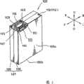
摄像机1包括:矩形固体摄像机主体2;镜头本体管3,该镜头本体管3在摄像机主体2的上部;显示面板(未示出)等,该显示面板在摄像机主体 2的左侧表面上。
另外,在摄像机主体2的右侧表面上有电池装载部分10,该电池装载部分由四个框架体(前框架体、后框架体、上框架体、下框架体)包围(参考图1和2)。In addition, there is a
当从前面看时,电池装载部分10形成为矩形,并形成为稍大于电池组100的前部凸起形状。而且,沿左右方向延伸的小肋16、16...分别布置在前框架本体11的内表面(后表面)11a和后框架本体12的内表面(前表面)12a偏向上端和底端的位置处,尽管该小肋16的凸出量较小,而且在靠近电池装载部分10的底表面15的位置处的肋形成为凸出量稍微大些,也就是形成为逐渐变细。在底表面15处彼此相对的小肋16、16之间的间隔形成为近似等于或稍微小于电池组的前后(宽度)尺寸(参考图3)。The
在构成电池装载部分10的上框架体13的前部的内表面13a上,提供有端子30(下文称为“主体侧端子”),用于与上述电池组100的端子120(下文称为“电池组侧端子”)连接,用于将电池组100保持在电池装载部分10中的锁定机构40设在底框架体14的中心(参考图1)。On the
首先介绍将用于摄像机1的电池组100。First, the
电池组100包括:矩形固体电池壳体101;电池102、102,该电池102、102将装在电池壳体101内;基片104,该基片上装有IC芯片103,用于计算和储存电池组等的残余量;以及电池侧端子120,该电池侧端子120将安装在基片104上,用于与主体侧端子30相连(参考图4)。The
其中,电池组100有多种电池组,主要因为它们的容量不同,图1、图3至9、图13至16中所示的电池组属于标准型电池组,在多种电池组100中,该电池组的外形最小(厚度薄)。Among them, the
这时,电池壳体101包括前表面壳体105和后表面壳体106(参考图4),在多种类型的电池组100中,尽管前表面壳体105的尺寸(厚度)并不相同,但是该后表面壳体106的尺寸都相同(参考图37至图40)。At this time, the
在后表面壳体106的上表面的前部,形成有凹入部分107,该凹入部分107是低于其它部分的凹槽,且在该凹入部分107处形成有矩形切口108,该矩形切口108开口于前表面侧(右侧方向)和后表面侧(左侧方向),同时上述电池侧端子从前表面侧(右侧)滑入,以便安装在矩形切口108上。安装在矩形切口108上的电池侧端子120的上表面的高度与除凹入部分107 外的其它部分的高度相同(参考图9)。In the front part of the upper surface of the
在后表面壳体106的矩形切口108的前后侧边缘处分别形成有肋(下文称为“端子定位肋”)109、109,该肋109、109向上凸出,同时沿左右方向延伸,端子定位肋109、109左端形成于从后表面壳体的后表面106a稍微靠右的位置处,并不延伸到后表面壳体106的后表面106a,同时这两个端子定位肋109、109的上表面的高度与除了电池侧端子的上表面和后表面壳体106的凹入部分107之外的其它部分的高度相同(参考图9)。Ribs (hereinafter referred to as "terminal positioning ribs") 109, 109 are respectively formed at the front and rear side edges of the
而且,两个端子定位肋109、109之间的间隔形成为近似等于上述电池侧端子120的前后方向的尺寸,两个端子定位肋109、109从安装的电池侧端子120的右侧边缘部分向右延伸,分别沿彼此相反方向(向前和向后方向)延伸的小凸出条110、110与定位肋109、109的左端形成一体。在电池侧端子120附近形成的凸出部分例如小凸出条110、110和上述端子定位肋109、109起到识别标记111、111的作用,用于识别电池组100的种类,这将在后面介绍(参考图7)。Moreover, the interval between the two
当前表面壳体105与后表面壳体106组合时,上述端子定位肋109的右端109a从后表面壳体106伸出,且当电池组100装在摄像机主体2的电池装载部分10上时,该端子定位肋109的右端部分109a成为一个上侧要锁定部分112,这将在后面介绍(参考图8)。When the
在后表面壳体106的上表面的后侧拐角部分处提供有比较小的凹形部分113,该凹形部分113向上侧和后侧开口,当电池组100装在电池装载部分10上时,该小凹形部分113成为一个上侧要锁定部分112(参考图8)。At the rear side corner portion of the upper surface of the
而且,在后表面壳体106的底表面106b上形成有凹形条要锁定槽114,该凹形条要锁定槽114沿前后方向延伸,在摄像机主体2侧的锁定机构40的锁定爪将锁定在该凹形条要锁定槽114内(后面将介绍),该要锁定槽114起到电池组100的底侧要锁定部分112的作用(参考图6)。Moreover, on the
这样,通过在电池组侧的后表面壳体106的多个部分(也就是在一个部件的多个部分)提供要锁定部分112(端子定位肋109的右端部分109a、凹形部分113以及要锁定槽114),因此,电池组100在装在电池装载部分10上时的位置精度可以提高(参考图15)。In this way, the portion to be locked 112 (the
即,通过使后表面壳体106的后表面106a(左侧表面)与底表面15接触(参考图15),同时使在电池组侧多个部分处的要锁定部分112(端子定 位肋109的右端部分109a、凹形部分113以及要锁定槽114)由电池装载部分10侧的相应锁定部分(后面将介绍的伸出部分17、小凸形部分20、锁定爪41)锁定,从而将电池组100装在电池装载部分10上。如果多个要锁定部分112、112...布置在不同部件上,例如布置在后表面壳体106和前表面壳体105上,那么当后表面壳体106和前表面壳体105装配不精确时,可能在锁定状态下产生游隙,并引起电池侧端子120和主体侧端子30之间的连接状态的问题。That is, by bringing the
这时,通过在电池组100中使前述要锁定部分112集中布置在一个部件(后表面壳体106)上,可以提高电池组100处于装载状态时的位置精度,这可以使后表面壳体106和前表面壳体105之间的连接精度不必很精确。At this time, by arranging the aforementioned to-
此外,在前表面壳体105的上侧前部并对应于上述电池侧端子120的区域中形成有凹口部分115,该凹口部分115的高度近似与后表面壳体106的凹形部分107相同,在该凹口部分115的左侧边缘处形成有端子推压肋116,用于从右侧推压电池侧端子120(参考图7至9)。In addition, a
端子推压肋116沿前后方向的长度形成为近似与上述后表面壳体106的两个端子定位肋109、109之间的间隔相同,也就是,几乎与电池侧端子120沿前后方向的尺寸相同,因此,当前表面壳体105装配到后表面壳体106上时,端子推压肋116定位在上述端子定位肋109、109之间,并从左侧推压电池侧端子120,后表面壳体106的两个端子定位肋109、109比端子推压肋116稍微更向右凸出,而作为要锁定部分112、112(参考图8)。The length of the terminal
对于标准容量类型的电池组100,两个矩形固体电池102、102以前后对准的方式装于电池壳体101中,上述基片104安装在电池的上部,上述电池侧端子120安装在基片104前部,而上述IC芯片103等安装在该基片104的后部(参考图4)。For the
这样,因为电池侧端子120布置在相对于电池组100沿一个方向偏移的位置处,因此可以在其相对侧部分处提供相对较大的空间,可以在该空间中布置电子部分,例如IC芯片103等,以便提高空间使用效率。特别是,当矩形固体电池102布置在电池壳体101中时,没有死空间,因此,电池102、102可以高效布置在电池组100内。尽管难以保证布置在基片104上的电池侧端子120、IC芯片103等从电池102上凸出的部件,但是通过如上述将电池侧端子120布置在相对于电池组100偏移的位置,可以有效利用空间(参 考图4和7)。In this way, since the
另外,因为电池侧端子120布置在相对于电池组100偏移的位置,可以防止将电池组错误装入摄像机主体2中。In addition, since the
后面将详细介绍电池侧端子120和容纳该电池侧端子120的矩形切口108的详细形状以及它们的装配方法。Detailed shapes of the battery-
下面将详细介绍摄像机主体2的电池装载部分10。The
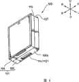
摄像机主体2的电池装载部分10从顶部到底部的尺寸形成为稍微大于上述电池壳体101的后表面壳体106的厚度(沿左右方向的厚度)。因此,当电池组100装在电池装载部分10上时,后表面壳体106布置在电池装载部分10的内部,几乎全部前表面壳体105从摄像机主体2中凸出(参考图3和15)。The
主体侧端子30布置在与上述电池侧端子120相对的位置处,也就是,在上框架体13的内表面(底侧表面)和底表面15之间的拐角部分处,或者在斜上部前侧的位置处(参考图10)。The main
在与布置有上述主体侧端子30的位置相对应的区域中,形成有向下凸出的伸出部分17,该区域是上框架体13的内表面13a的开口侧边缘(右侧边缘),且该伸出部分17和电池装载部分10的底表面15之间的尺寸形成为与上述后表面壳体106的后表面106a和端子定位肋109的右端部分之间的尺寸相同(参考图15)。In a region corresponding to the position where the above-mentioned main
因此,当电池组100装在电池装载部分10上时,端子定位肋109的右端部分109a由该伸出部分17锁定,在它们之间没有游隙。因此,可以在电池组100的上部的前侧区域没有游隙的情况下进行锁定(参考图15)。Therefore, when the
从伸出部分17的后部朝着电池装载部分10的底表面15(左侧方向)成一体形成有凸出条(下文称为“阻挡凸出条”)18,该阻挡凸出条18的顶端部分延伸到离该底表面15一定距离的位置(参考图10),这样,它不会与上述电池组100的后表面壳体106的上述识别标记111干涉。A protruding strip (hereinafter referred to as "blocking protruding strip") 18 is integrally formed from the rear of the protruding
这样的阻挡凸出条18和在主体侧端子30附近的较小凸出部分18a(后面将介绍)起到阻挡部分19的作用,用于判断是否装有电池组100。同时,因为上述阻挡部分19并不与电池组100的识别标记111干涉,因此能够将电池组100装在电池装载部分10上,尽管在用于装电池组10的装置例如摄像灯(具有较低容量的电池组100不能装在该摄像灯上)中,由于电池组100 的容量不同而可能有不允许装载电池组100的情况。Such a blocking
在这种情况下,设计成使上述阻挡部分19延伸到电池装载部分10的底表面15附近,以便与上述识别标记111干涉,从而阻止电池组100的装载。是否允许装载电池组100将取决于上述电池组100侧的识别标记111和上述阻挡部分19之间的形状和位置关系,这将在后面介绍。In this case, the blocking
在与上述后表面壳体106的小凹形部分113相对应的位置处形成有小凸形部分20,该位置是电池装载部分10的上框架体13的内表面(底侧表面)13a的后侧和后框架体12的内表面(前侧表面)12a之间的拐角部分,该小凸形部分20恰好与小凹形部分113啮合(参考图10),且该小凸形部分20离电池装载部分10的底表面15的位置与上述小凹形部分113的位置离后表面壳体106的后表面106a的位置相一致。因此,当电池组100装载电池装载部分10上时,电池组100在上部的后侧区域中的锁定在没有任何游隙的情况下进行。A small
矩形孔(下文称为“上推板布置孔”)21形成于电池装载部分10的底表面15的底部中心处,并在底框架体14的内表面(上侧表面)中有切除部分(下文称为“锁定杆布置孔”)22,该切除部分22与前述上推板布置孔21连续。A rectangular hole (hereinafter referred to as “upper push plate arrangement hole”) 21 is formed at the bottom center of the
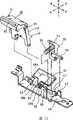
锁定机构40包括:锁定杆42,该锁定杆42有锁定爪41,该锁定爪41与形成于电池组100的底表面上的要锁定槽114啮合;上推板43,用于沿使底表面106a脱开的方向推压电池组100的底表面106a;防跳出杆,该防跳出杆44用于在通过前述锁定杆42释放锁定时防止电池组100跳出,且这些锁定杆42、上推板43以及防跳出杆44通过在底框架体14和底表面15之间的拐角部分内侧上的基板45可旋转地支承在相同轴上(参考图11和12)。The
然后,基板45装于底框架体14内部并固定在底框架体14上,且上述锁定杆42布置在底框架体14的上述锁定杆布置孔22内,上推板43布置在上推板布置孔21内,防跳出杆44布置在与孔22连续形成的矩形切除部分(下文中称为“防跳出杆布置孔”)46内。Then, the
此外,螺旋扭转弹簧48的线圈部分48a环绕旋转轴47安装,该旋转轴47可旋转地支承锁定杆42、上推板43和防跳出杆44,且该弹簧48的一个臂部分48b作用在锁定杆42上,另一个臂部分48c作用在上推板43上,以便可旋转地沿向上方向推动锁定杆42以及沿向右方向推动上推板43(参考 图12)。In addition, a
锁定杆42的外形是这样,整个锁定杆为字母L形,并侧向放置,并且有:上表面件49,该上表面件49形成上述底框架体14的内表面(上侧表面)的一部分;锁定爪41,该锁定爪41有三角形截面,沿前后方向形成,并延伸到偏离上表面件49的旋转中心的位置;以及操作部分50,该操作部分50形成于右侧表面的底部处,用于操作该锁定杆42(参考图11和12)。The profile of the locking
然后,锁定爪41形成为这样,它从电池装载部分10的底表面15稍微向右(前侧)偏移,其中,离该底表面15的距离等于要锁定槽114离上述电池组100的底表面106a的距离,这样,当锁定爪41与要锁定槽114啮合时,电池组100将压靠在电池装载部分10的底表面15上(参考图15)。Then, the locking
此外,在锁定杆42的上表面件49的左侧部分和右侧部分上都分别形成有小凸起51、51,该小凸起51、51与底框架体14的锁定杆布置孔22的边缘部分接触,同时凸起51、51从内侧与上述锁定杆布置孔22的边缘部分相撞,从而阻挡由上述螺旋扭转弹簧48引起的旋转。在该状态下,上表面件49的上表面与底框架体14的上表面平齐。In addition,
上推板43有成一体形成的较小部件52、52,该较小部件52、52从旋转中心向下凸出,同时该较小部件52、52与上述基板45接触,从而阻挡由上述螺旋扭转弹簧48引起的旋转。在该状态下,上推板43处于从上推板布置孔21向右凸出的状态(参考图12)。The
防跳出杆44有螺旋压缩弹簧54,该螺旋压缩弹簧54在防跳出杆的旋转端的底表面和凸出件53之间成压缩形状,因此,沿向上方向可转动地促动该防跳出杆44,与前述锁定杆42一样(参考图13至16)。顺便说明,在图13至16中,上述电池侧端子120和主体侧端子30都省略。The
防跳出杆44有爪部分55,该爪部分55形成于向上凸出的旋转端,且该防跳出杆44在其底端部分有成一体形成的旋转阻挡件,该旋转阻挡件56向前凸出。通过使旋转阻挡件56与形成于基板中的限制件57相撞,将阻挡由上述螺旋压缩弹簧54引起的旋转。在该状态下,上述爪部分55从底框架体14的上表面向上凸出(参考图13至16)。The anti-jump-out
此外,防跳出杆44的爪部分55形成为比锁定杆42的锁定爪41更靠右(参考图13至16)。Further, the
这样,当电池组100并不处于装在电池装载部分10中的状态时,锁定 杆42的锁定爪41和防跳出杆44的爪部分从底框架体14的上侧表面向上凸出,上推板43处于从电池装载部分10的底表面向右凸出的状态(参考图13至16)。In this way, when the
因此,当电池组100装在电池装载部分10上时,该过程将以如下方式实现,装入的电池组100将通过上述锁定机构而在电池装载部分10中保持锁定状态。Therefore, when the
首先,电池组100在其上部倾斜的情况下插入电池装载部分10中,电池侧端子120(包括后表面壳体106的端子定位肋109和前表面壳体105的端子推压肋116)滑入电池装载部分10的伸出部分17的内部。然后,如前所述,因为在电池组100侧的识别标记111并不与在主体侧的部件(阻挡部分19)干涉,因此,电池组100的电池侧端子120、端子定位肋109和端子推压肋116能够深深地滑入伸出部分17中(参考图13)。First, the
这时,尽管图中未示出,但是上述电池侧端子120的端子部件122、122、122和主体侧端子30的三个端子件31、31、31分别彼此连接。At this time, although not shown in the figure, the above-mentioned
此外,如后面详细所述,当在电池组100侧部的识别标记111与在电池装载部分10侧部的阻挡部分19形成为彼此干涉时,上述电池侧端子120不能深深滑入电池装载部分10的伸出部分17中。因此,电池侧端子120的端子部件122与主体侧端子30的端子件31将不能彼此连接。In addition, as will be described later in detail, when the
而且,如果即使在装载部分10的阻挡部分19与电池组100的识别标记111彼此干涉时也强行将电池组100装在电池装载部分10上,那么将电池组装在该电池装载部分10上的可能性很小,因为当深深识别标记111推压阻挡部分19时使得上端电池装载部分10的上框架体13弯曲。Moreover, if the
不过,这时,因为阻挡部分19和识别标记111形成于两个端子120、30附近,主体侧端子30沿它的受压方向退出,导致两个端子不能彼此连接。因此,端子件31和端子部件122不能彼此接触,从而避免了电接触。However, at this time, since the blocking
然后,通过以电池组100的上部(电池侧端子120部分,它由伸出部分17锁定)作为旋转支点,电池组100的底部向左旋转,从而将它装在电池装载部分10上(参考图14和15)。Then, by taking the upper part of the battery pack 100 (the
这时,当上述锁定机构40的防跳出杆44的爪部分55被电池组100的底部左侧向下推开,爪部分55与要锁定槽114啮合(参考图14)。At this time, when the
而且,当电池组100的底部压靠在电池装载部分10上时,上述防跳出 杆44的爪部分55由要锁定槽114的边缘部分推开,同时,锁定杆42的锁定爪41由底部左侧边缘部分推开(底表面侧拐角部分),然后,锁定爪41与要锁定槽114啮合,以便完成电池组100的装载(参考图15)。And when the bottom of the
另外,在锁定爪41与要锁定槽114啮合之前,电池组100的底表面106a使上推板43向左旋转,这样,电池组100的底表面106a近似与电池装载部分10的底表面15进行面对面接触(参考图15)。In addition, before the locking
然后,这些锁定杆42、防跳出杆44和上推板43克服上述螺旋扭转弹簧48和螺旋压缩弹簧54的弹簧力而进行旋转。Then, these locking
这时,电池侧端子120的端子部件122与主体侧端子30的端子件31连接,同时,在电池组100上部的端子定位肋109的右端部分109a(要锁定部分112)与伸出部分17啮合,同时电池组100的凹形部分113(要锁定部分112)与电池装载部分10的小凸形部分20啮合。At this time, the
因此,在电池组100的上部,端子定位肋109的右端部分109a(要锁定部分112)和伸出部分17以及小凹形部分113(要锁定部分112)和小凸形部分20分别彼此啮合,同时,锁定爪41和要锁定槽114在电池组100的底部彼此啮合,这样,电池组100保持在电池装载部分10中(参考图15)。Therefore, in the upper part of the
锁定杆42的锁定爪41以及防跳出杆44的爪部分55向上推压电池组100,以便使电池组100压靠上框架体13,这样,进行它们沿上下方向的定位(参考图15)。The locking
因此,电池侧端子120压靠在主体侧端子30上,这样,端子部件122和端子件31之间将保持稳定连接状态。特别是,电池侧端子120和主体侧端子30在相对于电池组100向前偏移的位置处,且因为防跳出杆44在从前后方向的中部向前偏移的位置,也就是该防跳出杆44在与两端子120、30相对的位置,因此,电池组100由爪部分55向上推压,从而能够在端子部件122和端子件31之间保持稳定连接状态(参考图2)。Therefore, the battery-
还有,因为电池组100的底部由上推板43向上推压,且该上推板43通过锁定爪41和要锁定槽114之间的啮合而阻挡,因此进行沿电池组100的装载方向(左右方向)的定位,而且,因为电池组100通过形成于前框架体11的内表面(后侧表面)11a上和形成于后框架体12的内表面(前侧表面)12a上的小肋16、16进行调节,因此进行沿前后方向的定位(参考图3)。Also, since the bottom of the
已经以这样的方式装在摄像机主体2的电池装载部分10上的电池组100 将以如下方式拆开。The
也就是,首先,通过用手或手指按压操作部分50而使锁定机构的锁定脱开(参考图16)。That is, first, the lock of the lock mechanism is released by pressing the
当操作锁定杆42时,它克服螺旋扭转弹簧48的弹簧力而向下旋转,从而与电池组100的要锁定槽114脱开。When the
当锁定爪41与电池组100脱开时,电池组100的底部由上推板43向左推压,并从电池装载部分10的底表面15上升高(参考图16)。When the locking
这时,当电池组100的底部稍微从底表面15上升起时,防跳出杆44的爪部分55与要锁定槽114啮合。因此,尽管电池组100从电池装载部分10上升起,但是因为防跳出杆44的爪部分55卡住啮合槽114,电池组100不会无意中跳出。特别是,当摄像机1定位成上述方向(最初进行摄像的方向)时,即使电池组100的锁定脱开,防跳出杆44的爪部分55也将卡住要锁定槽114,这样,该电池组100不会从电池装载部分10中脱出,因此,能够防止电池组100从中跌落。At this time, when the bottom of the
然后,通过用手抓住底部已经升起的电池组100,并沿使电池组脱出的方向(向右)将该电池组100拉出,因为防跳出杆44的爪部分55和要锁定槽114之间脱开,从而很容易地使电池组100与电池装载部分10脱开。Then, by grasping the
下面将详细介绍电池侧端子120和怎样使它装配到电池组100上。Next, the
如上所述,电池侧端子120包括端子壳体121和端子部件122、122、122,该端子部件122通过插入模制而布置在端子壳体121内,且该端子壳体121自身为扁平实体立方块形状,并有五个槽123、123、124、124、124,这些槽形成为向上和向左开口(参考图17至19)。As described above, the
上述五个槽中,在前侧和后侧的两个槽123、123的宽度比其它三个槽124、124、124的宽度更大,并其形成为比其它三个槽124、124、124长度更长和深度更深,并作为用于相对于主体侧端子30定位的引导槽(参考图17至19),如后面所述。Among the above-mentioned five grooves, the width of the two
另外,上述五个槽的中间三个槽124、124、124作为端子布置槽124、124,有一对接触件125,该对接触件125在各个槽124中布置成彼此相对,用于装上述接触件125、125的容纳空间126形成于端子布置槽124、124、124的内部(参考图17和18)。这里,在图17和18中只通过虚线表示了一个端子部件122,省略了其它两个端子部件122、122。In addition, the middle three
而且,对这些引导槽123、123和端子布置槽124、124的开口侧边缘进行倒角处理,例如R拐角、倾斜拐角等。因此,如后面所述,主体侧端子30的引导件32、32和端子件31、31、31很容易地插入相应的槽123、123、124、124、124中(参考图26至28)。Also, the opening side edges of these
电池侧端子120的各端子部件122由彼此相对的接触件125、125形成一体、使一个接触件125与另一接触件125相连的基座件127以及引出件128整体形成,该引出件128钎焊在布置于电池壳体101中的基片104上,并沿与接触件125、125相反的方向从基座件127中伸出(参考图21、22)。Each
接触件125、125有嵌入上述端子壳体121中的基座部分,半圆形接触凸起部分125a、125a形成于它的顶端部分,该接触凸起部分125a、125a沿彼此接近的方向凸出,这两个接触凸起部分125a、125a处于彼此接触的状态,同时相互之间没有压力(所谓的零接触状态)。当看电池侧端子120的端子布置槽124、124、124时,只能看见两个接触凸起部分125a、125a(参考图20、21)。The
因此,当接触部分35插入端子布置槽124中时,它只与接触凸起部分125a、125a接触。接触部分35可以沿两个方向(左右方向和从上到下方向)的任意一个插入端子布置槽124中,因为接触件125、125的弹簧特性相同,因此能够保证端子120和30之间的接触稳定性。当然,该效果只限于只注意端子结构时的情况,在上述实施例中,对于将电池组100装在摄像机上,实际上只能从左右方向插入。Therefore, when the
基座件127在它安装在端子壳体121的右侧表面上的位置处露出,引出件128弯成直角,并从基座件127的底边缘向右延伸,以便与端子壳体121的底表面121a近似平齐(参考图20、21)。The
在端子壳体121的前侧和后侧表面上都形成有沿左右方向延伸的滑动凸形部分129、129,且该滑动凸形部分129、129是上述后表面壳体106的矩形切除部分108的前侧和后侧边缘,并与形成于端子定位肋109的底侧上的滑动槽117、117滑动啮合,这样,该电池侧端子120支承在后表面壳体106上(参考图9)。Sliding
后表面壳体106的滑动槽117、117的左端堵塞,这样,当电池侧端子与该滑动槽滑动啮合时,使得该电池侧端子120向左定位。也就是说,调节从后表面壳体106的后表面106a到电池侧端子的位置。The left ends of the
还形成有切割槽130、130,该切割槽130、130分别是右侧表面和前侧表面之间的拐角部分和在右侧表面和后侧表面之间的拐角部分处,并从上述滑动凸形部分129、129的上侧延续,且该切割槽130、130将与从上述端子推压肋116的前端和后端部分向左布置的凸起118、118啮合(参考图9)。Cutting
该电池侧端子120有三个引出件128、128、128,这些引出件钎焊在上述基片104的预定位置(前侧左拐角部分)处,并安装在基片104的前侧拐角部分上(参考图4和7)。另外,电子部件例如IC芯片103等安装在基片104的预定后侧位置上,电池侧端子120并不安装在该位置处(参考图7)。This
因此,电池组100的装配如下。Therefore, the assembly of the
也就是,电池102、102以前后对齐的状态彼此组合,上述基片104安装在电池102、102的上部上,上述电池侧端子120、IC芯片103等装在该基片104上(参考图4)。That is, the
然后,已经安装有该基片104的电池102、102从右侧插入后表面壳体106。这时,电池侧端子120从右侧滑动插入后表面壳体106的矩形切除部分108中(参考图7)。Then, the
然后,如上所述,电池侧端子120的滑动凸形部分129、129插入后表面壳体106的滑动槽117、117中。(参考图7)。Then, as described above, the sliding
最后,使前表面壳体105与后表面壳体106彼此组合,以便覆盖电池102(参考图8)。Finally, the
这时,前表面壳体105的凸起118、118与后表面壳体106的切割槽130、130啮合,同时,端子推压肋116推压端子壳体121的右侧表面,以便覆盖端子部件122的、从其右侧表面露出的基座件127、127、127。然后,沿左右方向定位电池端子120,同时使电池端子120保持在后表面壳体106和前表面壳体105之间。At this time, the
在前表面壳体105和后表面壳体106的开口周边通过超声波焊接而彼此连接的状态下,执行前表面壳体105和后表面壳体106之间的组合。另外,两者可以通过粘接剂彼此粘接,以代替超声波焊接。Combination between the
如上所述,电池组100可以由三个部分组成,这样,后表面壳体106、电池102(包括电池侧端子120、基片104等)、前表面壳体105沿一个方向装配。As described above, the
下面将详细介绍主体侧端子30和上述电池侧端子120的组合。The combination of the main
首先,主体侧端子30布置在上述位置(前部后表面侧拐角),并包括:三个端子件31、31、31,这三个端子件31、31、31布置成从底表面15和上框架体13的内表面13a上凸出;两个引导件32、32,这两个引导件32、32布置成从前后方向夹住这些端子件31、31、31;以及保护板33,该保护板33可旋转地布置在上框架体13上,以便覆盖各端子件31、31、31的上部空间(参考图22和23)。First, the main
从前后方向看,端子件31为矩形平板,其中,它的上边缘和左侧边缘嵌入上框架体13中,引出部分34布置成从上框架体13凸出(参考图24),从上框架体13暴露的部分(底边缘和右侧边缘)作为接触部分35保持在上述电池侧端子120的接触件125、125之间,且它的端部侧边缘进行了倒角。Viewed from the front and rear directions, the
三个端子件31、31、31形成为有与上述电池侧端子120的端子布置槽124、124、125相同的间距,且各端子件31的厚度形成为近似等于形成于上述电池侧端子120中的端子布置槽124的宽度的一半(参考图22和23)。The three
当从前后方向看时,引导件32为矩形形状,与上述端子件31的形状类似,并与上框架体13和电池装载部分的底表面15形成一体(参考图24)。When viewed from the front-to-back direction, the
此外,当从前后方向看时,引导端子32、32比端子件31的接触部分35更大,它的板厚度形成为比端子件31更厚。而且,引导端子32、32形成为间距与形成于上述电池端子120中的引导槽123、123之间的间距相同,且各引导件32、32的板厚度形成为稍微小于上述电池侧端子120的端子壳体121的引导槽123、123的宽度,且它的端部侧边缘进行倒角(参考图23)。Furthermore, the
如上所述,因为引导件32形成为比端子件31的接触部分35更大,因此,当主体侧端子30将与电池侧端子120组合时,与接触部分35进入端子槽124相比,引导件32更早进入引导槽123中(参考图26)。As described above, since the
保护板33支承在靠近上框架体13的内表面(底侧表面)的前端部分的开口侧边缘(右侧边缘)的位置处,以便沿上下方向自由旋转(参考图24和25)。具体的说,在上框架体13的内表面(底侧表面)的前端部分处形成有凸形保护框架壳体13b,在保护板33的前、后侧边缘处成一体形成有支承轴凸出部分36、36,用于可旋转地与上述保护板壳体部分13b的右端两侧部分啮合,线圈弹簧37环绕该支承轴凸出部分36前侧布置。当从向后方向看时,将沿逆时针方向推动该保护板33(参考图24、25)。The
在保护板33的旋转支点部分处提供有旋转阻挡部分38、38(图中只表 示了其中的一个),该旋转阻挡部分38、38与上框架体13接触,以便阻挡上述逆时针方向旋转,且当保护板33的旋转端定向成向左斜向下方向时(大约45度),保护板33成为逆时针方向侧的旋转端(参考图10a、24和29)。此外,保护板33的顺时针方向侧的旋转端在它装于上框架体13的保护板壳体部分13b中的位置,或者近似处于水平位置(参考图10b)。At the rotation fulcrum part of the
保护板33沿前后方向的尺寸稍微小于上述引导件32、32之间的距离,并总在两个引导件32、32之间进行旋转。在与上述端子件31相对应的位置处形成有狭槽39、39、39,该狭槽开口于旋转端侧边缘。因此,当保护板33向上旋转时,各端子件31、31、31插入这些狭槽39、39、39中,以便允许保护板33旋转,同时使该端子件31、31、31在旋转时露出(参考图10、22和23)。这里,图10(a)表示了保护板已经旋转时的状态,而图10(b)表示了保护板没有旋转时的状态。The size of the
然后,当外力并不施加在保护板33上时,在保护板33沿逆时针方向的旋转端处,在两个引导件32、32之间的拐角部分处于覆盖保护板33的旋转端边缘的两侧端的状态(参考图24)。此外,在该状态下,上述各端子31、31、31的接触部分35、35、35的拐角处于与上述狭槽39、39、39啮合的状态(参考图25)。Then, when an external force is not applied to the
然后,如下面详细所述,当电池组100装在电池装载部分10上时,电池侧端子120的端子壳体121推压上述保护板33,以便使该保护板33克服螺旋扭转弹簧37的弹簧力顺时针方向旋转,并终止于处在上框架体13的保护板壳体部分13b中的位置(参考图29)。Then, as described in detail below, when the
因此,主体端子30的接触部分35、35、35露出并相对地进入端子壳体121的端子布置槽124、124、124中,以便保持在一对接触件125、125之间,并形成电接触(参考图28)。Therefore, the
这样,当保护板33处于并不受到外力的状态时,因为保护板33处于覆盖接触部分35、35、35的状态,接触部分35、35、35并不暴露,从而防止外部材料粘在该接触部分上(参考图25)。In this way, when the
此外,当在主体端子30的部分上发生任何类型的碰撞时,例如当电池组100以错误方向装载时(错误装载),不同于电池端子120的部件可能与主体侧端子30相撞。Furthermore, when any type of collision occurs on a portion of the
即使在该情况下,因为引导件32、32形成为大于接触部分35、35、35, 因此,外力主要作用在引导件32、32上,而不是作用在接触部分35、35、35上,从而防止接触部分35、35、35变形。Even in this case, since the
而且,当相对较小的外部材料与主体侧端子30相撞时,由于存在上述保护板33,它们在与端子件31(接触部分35)相撞之前与保护板33相撞,因此,减缓了外力,从而使接触部分35不会直接受到较大外力。Moreover, when relatively small external materials collide with the main
而且,如上所述,因为保护板处于保持在两个引导件32、32之间的状态,当具有前后方向分量的外力施加在保护板33上时,因为引导件32、32用于支承保护板33,还因为如上所述三个相应的接触部分35、35、35插入狭槽39、39、39中,因此,外力通过相应狭槽39、39、39作用在接触部分35、35、35上,以防止保护板33前后方向移动。因为外力不是作用在一个接触部分35时,因此可以防止接触部分35、35、35变形。Also, as described above, since the protective plate is in a state held between the two
在上述实施例中,这样的主体侧端子30可以有成一体形成于上框架体13部分处的引导件32、32,并有通过插入模制成一体形成的端子件31、31、31,或者还提供有可旋转的保护板33,或者是,主体侧端子可以有相应部分,该部分模制或形成为预定形状的基座部件中的另外部件,以便将该部件安装在上框架体13上作为端子。In the above-described embodiment, such a main
下面将介绍在将电池组100装载电池装载部分10上时怎样使电池侧端子120与主体侧端子30相连。How to connect the
首先,电池组100有倾斜布置的电池侧端子120(包括端子定位肋109、端子推压肋116),以便布置到上框架体13的伸出部分17下面,从而使主体侧端子30和电池侧端子120彼此相对。First, the
然后,当电池侧端子120布置到上述伸出部分17下面时(参考图13),主体侧端子30的引导件32、32相对地插入电池侧端子120的引导槽123、123中(参考图26)。这时,因为引导槽123、123有进行倒角的开口侧边缘,且引导件的端部侧边缘也进行了倒角,因此将使两者容易安装。Then, when the
在该条件下,引导件32、32处于稍微插入引导槽123、123中的状态,因此使电池端子120相对于主体端子30进行定位。如上所述,在接触件125、125与接触部分35、35、35接触之前,因为由模制部件组成的引导件32、32引导槽125、125啮合,因此,通过精确形成部件,能够进行定位。因此,在两个端子120、30的接触件125、125和接触部分35之间彼此接触之前,两个端子120、30能够精确定位,因此,随后在接触件125、125和接触部 分35之间的接触可以高度精确地进行。In this condition, the
从该状态,电池组100的底部进行旋转,然后装在电池装载部分10上。电池组100的旋转通过使后表面壳体106的要锁定部分被由上述伸出部分17卡住来进行,该区域作为旋转支点(参考图14)。From this state, the bottom of the
然后,主体侧端子30的接触部分35相对进入电池侧端子120的端子布置槽124中(参考图27),并与两个接触凸形部分125a、125a接触,且将这两个接触凸形部分推开,这样,接触部件125、125弹性弯曲,并夹住接触部分35。因此,在电池侧端子120和主体侧端子30之间建立电连接(参考图28)。Then, the
此外,接触部分35和接触件125、125之间的关系为这样,即接触部分35沿表面方向相对运动,且因为两个接触件125、125以其顶端部分(接触凸形部分125a、125a)被推动彼此离开的方式弹性弯曲,不合适的力不会作用在它们之间,因此,接触部分35和接触件125、125不会变形。In addition, the relationship between the
而且,因为电池侧端子120和主体侧端子30之间的关系为这样:电池侧端子120的、沿两个方向开口的端子布置槽124、124、124与扁平板状接触部分35、35、35接触,该扁平板状接触部分35、35、35有近似直角的拐角,电池侧端子120可以从90度范围的方向与主体侧端子30组合,该方向包括左右方向和上下方向。Also, because the relationship between the
也就是,当只考虑电池侧端子120和主体侧端子30的结构时,电池侧端子120可以从包括前述方向的左侧或底侧或左斜下侧而与主体侧端子30组合,这意味着该电池侧端子120可以从大约90度的范围内的任意方向与主体侧端子30进行组合,而且,在沿该方向进行的任意组合中,不合适的力都不会作用在接触部分35和接触件125、125上,因此接触部分35和接触件125、125都不会变形。That is, when only the structures of the battery-
当然,在上述电池组100和摄像机主体2的电池装载部分10之间的关系中,因为电池侧端子120将大约从左侧与主体侧端子30组合,因此,可以说电池侧端子120和主体侧端子30的结构并没有充分利用。Of course, in the above-mentioned relationship between the
不过,因为将上述电池组100装在电池装载部分10上通过旋转来进行,因此,端子120和30的组合并不是只有一个方向的方向分量,通过采用该端子结构,端子120和30的接触部分35和接触件125、125在彼此接触时并不会受到不合适的力,从而不会变形。However, since the above-mentioned
此外,因为在接触件125、125的顶端部分提供有接触凸形部分125a、125a,从而使该接触凸形部分125a、125a与接触部分35接触,因此,两个端子还可以在包括上述两个方向的90度范围内彼此组合。In addition, since the contact
也就是,尽管接触部分35进入并推开接触件125、125,从而使接触件彼此离开,但是,因为接触部分35只与接触凸形部分125a、125a接触,因此,在两个端子120、30从包括上述两个方向的90度范围内的任意方向进行的任意组合中,电池装载部分10可以以相同的方式接收电池组100。That is, although the
而且,因为接触凸形部分125a、125a在接触件125、125的顶端部分处,因此,即使当接触件125、125和接触部分35沿前后方向的位置稍微偏移,也可以在两个端子(接触件125、125和接触部分35)之间保持稳定的连接状态。Also, since the contact
下面将介绍端子部件122的材料质量和宽度,它们将影响两个端子120和30组合时在接触件125、125和接触部分35之间的接触状态。The material quality and width of the
端子件31由黄铜制成(厚度:t=0.35mm),它的接触部分镀有0.76μm厚的金。而且,选择黄铜作为端子件31的材料的原因是因为从成本和可加工性考虑,通常采用黄铜、磷青铜、铍铜作为接触点。The
而且,着眼于增加安全性,对于镀金,镍层可以用作基层,0.75的厚度设置成用眼睛看,因为考虑到电池组100和摄像机1的使用情况,电池组频繁进行重复地插入和拔出。Also, with an eye on increasing safety, for gold plating, a nickel layer can be used as a base layer, and the thickness of 0.75 is set to be seen by eyes, because considering the use of the
因此,当用于摄像机1和电池组100的端子结构,接触凸形部分125a、125a完全可以不用镀金,以避免如通常使用时的浪费。Therefore, when used in the terminal structure of the
此外,0.76μm的镀金厚度主要用于接触部分,也就是接触部分35,不过对于引出部分34,推荐的镀金层厚不超过0.1μm。这用于保证两者之间的稳定电接触。In addition, the gold plating thickness of 0.76 μm is mainly used for the contact portion, that is, the
然后,对于端子部件122,对四个实例进行了试验,以便从中选择一个。对于该试验的材料,如上所述考虑了三种材料(黄铜、磷青铜、铍铜),但是考虑到接触件125、125的弹簧力,对磷青铜和铍铜进行了试验,因为它们的特性有利。Then, for the
试样(1)采用磷青铜(厚度:t=0.2mm)作为材料,同时对接触部分镀上0.76μm的金;试样(2)采用磷青铜(厚度:t=0.15mm)作为材料,同时对接触部分镀上0.76μm的金;试样(3)采用铍铜(厚度:t=0.2mm)作 为材料,同时对接触部分镀上0.76μm的金;试样(4)采用铍铜(厚度:t=0.15mm)作为材料,同时对接触部分镀上0.76μm的金。而且,对于镀金,镍层用作基层,如上述端子部件122那样。此外,选择0.76μm层厚的原因也相同。而且,在接触件125、125上的0.76μm镀金与接触部分上的厚度相同,也就是与接触凸形部分125、125上的相同,并推荐在引出件128上的镀金不超过0.1μm厚。Specimen (1) is made of phosphor bronze (thickness: t=0.2mm) as material, and the contact part is plated with 0.76μm gold; specimen (2) is made of phosphor bronze (thickness: t=0.15mm), and at the same time The contact part is plated with 0.76μm gold; sample (3) is made of beryllium copper (thickness: t=0.2mm) as material, and the contact part is plated with 0.76μm gold; sample (4) is made of beryllium copper ( Thickness: t = 0.15 mm) was used as the material, while the contact portion was plated with 0.76 µm of gold. Also, for gold plating, a nickel layer is used as a base layer, as in the
对于试样方法,进行了耐久性试样,其中,端子件31插入端子部件122内和从该端子部件122内拔出7000次。For the test method, a durability test was performed in which the
对例如接触电阻、总啮合力、总脱开力和外观检查等项目进行试验,前三个试验项目表示了从1到7000的预定次数的相应值,此外,外观检查在经过7000次耐久性试验后通过视觉观察进行。Test items such as contact resistance, total engagement force, total disengagement force, and visual inspection. The first three test items represent the corresponding values from 1 to 7000 predetermined times. In addition, the visual inspection is performed after 7000 durability tests. followed by visual observation.
而且,接触电阻通过采用四端子方法进行测量,其中,开路电压设置成不超过20mV,短路电流不超过100mA,规定值为最大20mΩ。Also, the contact resistance was measured by using the four-terminal method, in which the open circuit voltage was set to not exceed 20mV, the short circuit current to not exceed 100mA, and the specified value was 20mΩ maximum.
通过使端子120和端子30啮合(组合)来测量总啮合力,然后测量啮合力,该啮合力设置成最大10N(牛顿)。The total engaging force is measured by engaging (combining) the
对于总脱开力,在释放端子120和端子30之间的啮合(组合)时测量脱开力,该脱开力设置成最小0.3N(牛顿)。For the total disengagement force, the disengagement force is measured when the engagement (combination) between the terminal 120 and the terminal 30 is released, and the disengagement force is set to a minimum of 0.3 N (Newton).
前述三个试验项目的试验结果如图31至33所示。The test results of the aforementioned three test items are shown in FIGS. 31 to 33 .
对于试样(1),接触电阻显示发散较小且稳定(参考图31),插入拔出力也能稳定地获得良好值(参考图32和33)。此外,外观检查显示接触件125、125的接触凸形部分125a、125a磨损量合适,没有发现问题。For the sample (1), the contact resistance showed little divergence and was stable (refer to FIG. 31 ), and the insertion and extraction force also stably obtained good values (refer to FIGS. 32 and 33 ). In addition, the visual inspection revealed that the contact
对于试样(2),接触电阻显示在7000次耐久性试样中有较大发散,总啮合力较小(参考图32)。此外,外观检查显示有几个擦痕。还观察到总啮合力较弱,致使接触压力较小,从而引起接触电阻问题。For the sample (2), the contact resistance showed a large divergence in the 7000-times durability sample, and the total engagement force was small (refer to FIG. 32 ). Also, visual inspection revealed several scratches. It was also observed that the overall meshing force was weaker, resulting in lower contact pressure, which caused contact resistance problems.
对于试样(3),尽管接触电阻和总啮合力都没有问题,但是在7000次耐久性试样中脱开力变化较大,在脱开时将有所谓的急动感觉。而且,外观检查显示有更大的啮合力变化,在端子件31上产生更大磨损擦伤,而且,端子件31的接触凸形部分125a、125a磨损更严重。As for the sample (3), although there is no problem in the contact resistance and the total engaging force, the disengagement force varies greatly in the 7000-times durability sample, and there will be a so-called jerk feeling at the time of disengagement. Furthermore, the visual inspection revealed a greater change in the engagement force, greater wear and tear on the
对于试样(4),总啮合力较弱,接触电阻相对稳定,尽管这隐藏了接触电阻值可能出现的问题。此外,外观检查显示可以达到总啮合力较小、几乎没有磨损擦痕的程度。For specimen (4), the overall meshing force is weak and the contact resistance is relatively stable, although this hides possible problems with the contact resistance value. In addition, visual inspection showed that a low total engagement force and little or no wear marks could be achieved.
因此,对于四个试样,可以认为试样(1)最合适。Therefore, among the four samples, it can be considered that sample (1) is the most suitable.
而且,对于铍铜,在对铍铜进行镀金时,只能进行所谓的后电镀(电镀处理在制成预定形状后进行),因此选择试样(1)。Furthermore, for beryllium copper, only so-called post-plating (plating treatment is performed after forming a predetermined shape) can be performed when gold-plating beryllium copper, so sample (1) was selected.
也就是,铍铜通常难以在镀金后进行成形(压力加工,例如弯曲和锻造),因此,采用上述端子部件22的形式,它在成形后的形状为接触凸形部分125a、125a彼此接触,因此,当对有这样的接触部分的任何物件进行镀金时,接触部分不能通过后电镀而进行镀金,因为它们彼此接触。That is, beryllium copper is generally difficult to form (press working, such as bending and forging) after gold plating, and therefore, in the form of the above-mentioned
同时,对于上述四个试样,它们都满足上述规定值(接触电阻:20mΩmax;啮合力:10Nmax;脱开力:0.3Nmin),因此选择任意一个实例都没有任何问题。不过,当考虑到更坏条件,试样(1)是优选选择,因为可获得良好结果。Meanwhile, for the above-mentioned four samples, they all satisfy the above-mentioned specified values (contact resistance: 20mΩmax; engaging force: 10Nmax; disengaging force: 0.3Nmin), so there is no problem in selecting any one of the examples. However, when considering worse conditions, sample (1) is the preferred choice because good results can be obtained.
而且,当考虑到接触件125、125的弹簧力的接触压力时,选择试样(1)作为端子部件122的材料(参考图34至36)。Also, when considering the contact pressure of the spring force of the
在下面的描述之前,先清楚地介绍一下端子部件122和布置该端子部件122的端子布置槽124的尺寸等(参考图34、35)。Before the following description, the dimensions and the like of the
如前所述,端子部件122的接触部件125、125的厚度为0.2mm,宽度为1.2mm,从埋入部分露出的部分的长度为3.9mm,所形成的上述接触凸形部分125a、125a,其r=0.3,从其边缘朝着中心基座件127侧偏离0.45mm的位置(参考图34和35)。此外,接触件125、125从埋入部分中伸出,这样,它们彼此接近,并大致在纵向方向的中心处弯曲而彼此平行,同时从弯曲部分到边缘部分,它们之间的间距形成为0.6mm。因此,接触凸形部分125a、125a彼此进行零接触(参考图21)。As mentioned above, the thickness of the
端子布置槽124的开口宽度形成为0.45mm,上述接触部分35的板厚t为0.35,因此,当接触部分35进入标准位置(中部)的端子布置槽124中时端子布置槽124的内边缘和接触部分35之间的间距为((0.45-0.35)/2=0.05mm)(参考图34和35)。The opening width of the
这时,两个接触件125、125有近似相同的弯曲,移动量为0.175mm。此外,这时的接触压力为1.0091N(参考图36)。At this time, the two
然后,当接触部分35通过沿一个方向偏移而进入端子布置槽124中时,对于一个接触件125产生最大量的移动,而对于另一接触件125则产生最小量的移动,因此,这时的接触压力分别为1.4416N和0.4609N(参考图36)。Then, when the
因此,在采用上述试样(1)的上述材料(磷青铜)的情况下,当接触部分35与接触凸形部分125a接触时,可以发现接触压力最大为1.4416N,最小为0.4609N,这足够作为接触压力。Therefore, in the case of using the above-mentioned material (phosphor bronze) of the above-mentioned sample (1), when the
当采用镀金时,通常0.09812N-0.1961N就足以作为接触压力,而在上述试样(1)中,施加的接触压力大于该值,这似乎太大。When gold plating is used, usually 0.09812N-0.1961N is sufficient as the contact pressure, while in the above sample (1), the applied contact pressure is greater than this value, which seems to be too large.
不过,因为端子结构基于使电池组100和摄像机1之间电接触的前提条件,很容易预计插入和拔出的次数很多,镀金可能磨损。However, since the terminal structure is based on the premise of making electrical contact between the
因此,即使在镀金磨损的情况下暴露出作为基层的镍层时,也必须保证接触电阻值低于规定值。Therefore, even when the nickel layer as the base layer is exposed when the gold plating is worn, it is necessary to keep the contact resistance value below the specified value.
这时,因为据认为当镍的接触压力为大致0.5884N时也能保证接触电阻为规定值,因此,通过保证一个接触件125的最大值1.4416N,而另一接触件125的上述最小值为0.4609N,即使在镀金磨损时也能满足规定值(参考图36)。At this time, since it is considered that the contact resistance can be guaranteed to be at a specified value even when the contact pressure of nickel is approximately 0.5884N, by securing the maximum value of 1.4416N for one
另外,绝缘电阻和耐压也作为与上述项目不同的项目来进行检查,结果,上述四个试样都在规定值内,没有发现任何特殊差异。In addition, insulation resistance and withstand voltage were also inspected as items different from the above items. As a result, the above four samples were all within the specified values, and no special difference was found.
而且,作为抗外界环境性能,对于潮湿电阻、温度循环和喷洒盐水的情况也进行了电性能和机械性能试验,结果没有任何特殊差异。Also, as resistance to external environments, electrical and mechanical performance tests were also conducted for the case of moisture resistance, temperature cycle, and salt water spraying, and the results did not show any particular difference.
在上述实施例中,引用了具有电池侧端子120的电池组100(要装载部件)和有主体侧端子30的摄像机(主体侧装置),并以它们为例进行了说明,但是,也可以是具有与电池组100相同的电池侧端子120的干电池组140(要装载部件)以及具有与摄像机1相同的主体端子30的摄像灯150和电池充电器160(参考图37至40)。In the above-mentioned embodiment, the
另外,相对于电池组100,根据容量的不同,可以有多种类型;对于摄像机1,包括有充电功能的可充电类型1A和没有充电功能的不可充电类型1B(参考图37至40)。In addition, with respect to the
当所有这些多种具有侧端子120的装置(多种电池组100、干电池组140等)都能够装在具有主体端子30的装置(摄像机1n(可充电类型1A和不可充电类型1B)、摄像灯150和电池充电器160)上时,将可能出现问题。When all these various devices having side terminals 120 (various battery packs 100, dry cell packs 140, etc.) 150 and battery charger 160), problems may arise.
例如,干电池组140能够装在摄像机1B(不可充电类型)上,但该干电池组140不能装在摄像机1A(可充电类型)和电池充电器160上,而且,对于摄像灯150,高容量类型的摄像灯150A只允许安装在电池组100的高 容量电池组100H,不能装载在其它的低容量电池组100L、标准容量电池组100S和干电池组140上。For example, the
这里,可充电类型摄像机1A装备有DC输入插座端子,且当DC输入插座与它相连时,摄像机主体2可以由装在电池装载部分10上的、正在充电的电池组100来驱动,而不可充电类型的摄像机1B是没有这样的充电功能的装置,在上述实施例中例举的摄像机1属于可充电类型1A,上述干电池组140不能装在该摄像机1A上。Here, the rechargeable
这时,需要判断有这样的电池侧端子120的电池组100能否装在有主体侧端子30的装置上,从而在判断不允许装载时防止它的装载。At this time, it is necessary to determine whether the
这时,识别标记111布置在上述电池侧端子120附近,而用于阻挡电池组100等装载的上述阻挡部分19在主体侧端子30附近的相应区域处。At this time, the
下面表示了电池侧端子120的识别标记111和主体侧端子30的阻挡部分19的具体实例。Specific examples of the
对于电池侧端子120的识别标记111的种类,有四种,例如L型、H型、D型和S型,L型识别标记111L用于低容量类型的电池组L,S型识别标记111S用于标准类型的电池组100S,H型识别标记111H用于高容量类型的电池组100H,而D型识别标记111D用于干电池组140(参考图37至40)。For the kind of
此外,对于主体侧端子30的阻挡部分19的种类,有四种,例如I型、II型、III型和IV型,I型阻挡部分用于可充电类型的摄像机1A(与电池充电器160相同),II型阻挡部分用于不可充电类型的摄像机1B,III型阻挡部分用于高容量专用的摄像灯150A,IV型阻挡部分用于非低容量摄像灯150B(参考图37至40)。In addition, for the kinds of the blocking
用于标准容量电池组100S的S型识别标记111S如上述构成,它有小凸出条110,该凸出条110从端子定位肋109的左端以彼此相反的方向(前后方向)伸出。识别标记S形成于从后表面壳体106的后表面106a大致向右侧偏移的位置(参考图37至40)。The S-shaped
用于低容量电池组100L的L型识别标记111L形成为这样:形成于上述S型识别标记111S的端子定位肋109的左端的小凸出条110延伸到后表面壳体106的后表面106a上,因此,L型识别标记111L的小凸出条110L形成为与后表面壳体106的后表面106a连续(参考图37至40)。The L-shaped
用于高容量电池组100H的H型识别标记111H形成为这样:并不形成 在上述S型识别标记111S和L型识别标记111L中以彼此相反方向(前后方向)延伸的小凸出条110、110L。The H-shaped
用于干电池组100D的D型识别标记111D形成为这样:并不与上述L和S型识别标记一样形成从端子定位肋109的左端伸出的小凸出条110、110L,但是在前表面壳体105中成一体形成有从端子推压肋116的中部向右伸出的识别肋141(参考图37至40)。The D-
下面将介绍相应阻挡部分19的结构以及该阻挡部分19怎样与上述相应识别标记111组合。The structure of the corresponding blocking
首先,在上述实施例中,主体侧端子30的I型阻挡部分用于摄像机1A(可充电类型1A),并包括形成于主体侧端子30的上框架体13中的伸出部分17以及形成为从伸出部分17的后端向左伸出的上述阻挡凸出条18(参考图37)。First, in the above-described embodiment, the I-type blocking portion of the main
在该I型阻挡部分中,因为伸出部分17的中心部分与D型识别标记111的识别肋141干涉,因此不允许对它进行装载,不过,对于其它L、S和H型识别标记,允许对它进行装载,因为伸出部分17的中心部分不会与该识别标记111干涉。In this type I blocking part, because the central part of the protruding
因此,干电池组140不能装在采用了I型阻挡部分的可充电类型摄像机1A上,因此,可以防止干电池组140错误充电的问题。另一方面,采用了其它类型的识别标记111L、111S、111H的电池组100L、100S、100H能够装在电池装载部分10上,不管它的容量为较高或较低(参考图37)。Therefore, the
在II型阻挡部分中,在伸出部分17的中心部分形成有切除部分17a,因此,因为伸出部分17不会与识别标记141干涉,因此能够对它进行装载,同时,不会有任何部分与其它类型的识别标记111S、111L、111H干涉,因此,所有类型的识别标记111L、111S、111H都允许装载(参考图38)。In the type II blocking portion, a cutout portion 17a is formed at the central portion of the protruding
因此,低容量电池组100L、标准容量电池组100S、高容量电池组100H以及干电池组140都能装在采用了II型阻挡部分的不可充电类型摄像机1B(参考图38)。Therefore, the low-
在III型阻挡部分中,朝着底表面15(向左)形成的阻挡凸出条18的一端部分到达电池装载部分10的底表面15,另一阻挡凸出条18在该阻挡凸出条18前面与上述底表面15形成一体。两个阻挡凸出条18之间的间距形成为近似等于两个端子定位肋109、109之间的间距,这两个端子定位肋109、 109形成为从前后方向夹住上述电池侧端子120(参考图39)。In the type III blocking part, one end portion of the
在该III型阻挡部分中,因为伸出部分17的中心部分与D型识别标记111D的识别标记141干涉,因此不允许对它进行装载,在L型识别标记111L和S型识别标记111S中,因为从端子定位肋109的左端沿彼此相反方向(前后方向)伸出的小凸出条110、110L与上述阻挡凸出条18、18干涉,因此也不允许对它们进行装载。而在H型识别标记111H中,没有与III型阻挡部分干涉的部分,因此能够对它进行装载(可图39)。In this type III blocking portion, since the central portion of the protruding
因此,低容量电池组100L、标准容量电池组100S和干电池组140都不能装在采用了III型阻挡部分的高容量专用摄像灯150A上,只有高容量电池组100H能够装在该高容量专用摄像灯150A上(参考图39)。Therefore, the low-
在IV形阻挡部分中,与上述I型阻挡部分相同的、从伸出部分17的后端朝着底表面15(向左)形成的阻挡凸出条18并不到达电池装载部分10的底表面15,较小凸出部分18a形成于它的延伸区域中,该较小凸出部分18a与电池装载部分10的底表面15接触,另一较小凸出部分18a在该较小凸出部分18a的前面从上述底表面15上成一体形成。然后,两个较小凸出部分18a、18a之间的间距形成为近似等于两个端子定位肋109、109之间的间距,这两个端子定位肋109、109形成为从前后方向夹住上述电池侧端子120(参考图40)。In the IV-shaped blocking portion, the blocking protruding
在该IV类型的阻挡部分中,因为伸出部分17的中心部分与D型识别标记111D的识别肋141干涉,因此不允许对它进行装载,在L型识别标记111L中,因为从端子定位肋109、109的左端沿彼此相反方向(前后方向)伸出的小凸出条110L、110L与上述较小凸出部分18a、18a干涉,因此,也不允许对它进行装载。在S型识别标记111S中,因为从端子定位肋109、109沿彼此相反方向(前后方向)伸出的小凸出条110、110形成于稍微离开电池组100的底表面106a的位置处,因此,没有与IV型阻挡部分干涉的部分,因此能够对它进行装配。此外,对于H型识别标记111H,因为没有与IV型阻挡部分干涉的部分,因此也能够对它进行装配(参考图40)。In this type IV blocking portion, because the central portion of the protruding
因此,低容量电池组100L和干电池组140并不能装在非低容量摄像灯150B上,而标准容量电池组100S和高容量电池组100H能够装在它上面(参考图40)。Therefore, the low-
同时,尽管图中未示出,但是在IV型阻挡部分的较小凸出部分18a附 近布置有检测开关,用于检测S型识别标记11S的小凸出条110的存在,以便判断它是S型识别标记111S还是L型识别标记111L。At the same time, although not shown in the figure, a detection switch is arranged near the small protruding portion 18a of the IV-type blocking portion for detecting the existence of the small
这时,上述非低容量摄像灯150B有两个电灯泡,当装载高容量电池组100H时,两个电灯泡都点亮,而当装载标准容量电池组100S时,点亮一个电灯泡。这样,通过分别在电池侧端子120和主体侧端子30附近提供有识别标记111和锁定部分19,可以在将电池侧端子120和主体侧端子30连接之前判断它释放能够装载,从而能确实避免在情况为“NO”时使两个端子相连。即,当在错误装载的情况下,因为在端子120和30附近提供有上述识别标记和阻挡部分,可以避免端子120和30进行连接,因此,可以避免端子部件122和端子件31之间接触。At this time, the above-mentioned non-low-capacity video light 150B has two bulbs, and when the high-
此外,上述对识别标记111和阻挡部分19的形状以及它们的位置的说明是作为实例。识别标记111和阻挡部分19可以在电池侧端子120和主体侧端子30附近,这不是限制该说明。而且,应当知道,这些形状和位置并不局限于电池组100、干电池组140、摄像机1(1A、1B)、摄像灯150和电池充电器160,而是可以考虑各种类型。In addition, the above descriptions of the shapes of the
而且,在上述实施例中,电池侧端子120的端子壳体121对应于要求保护的技术方案中所述的“要装载部件侧端子的模制部件”,而主体侧端子30的上框架体13等对应于要求保护的技术方案中所述的“主体侧端子的模制部件”。而且,如上所述主体侧端子30可以包括代替上述框架体的任意部件,其它这样的部件也可以通过在其中插入端子件而模制成为模制部件,同时,引导件可以与它一体形成。另外,电池侧端子可以使电池壳体作为上述电池部件,端子部件可以通过与形成的引导槽一起插入模制而形成。Moreover, in the above-described embodiment, the
此外,在上述实施例中,提供有两个引导件,三个端子件布置在这两个引导件之间。不过,并不限制于此,当有多个端子件时,本发明也可以在排成一行的端子件之间提供附加的引导件。Furthermore, in the above-described embodiments, two guide pieces are provided, and the three terminal pieces are arranged between the two guide pieces. However, it is not limited thereto, and when there are multiple terminal pieces, the present invention can also provide additional guide pieces between the terminal pieces arranged in a row.
而且,在上述实施例中所示的各部分的具体形状和结构只表示了实施本发明的实例,因此,本发明的技术范围并不局限于它们。Also, the specific shapes and structures of the respective parts shown in the above-mentioned embodiments are merely examples for implementing the present invention, and therefore, the technical scope of the present invention is not limited to them.
由上述可知,本发明的端子结构的特征在于为了在将要装载部件装在主体侧装置上时使该主体侧装置和要装载部件之间进行电连接,其中,主体侧装置有主体侧端子,要装载部件有要装载部件侧端子,用于与上述主体侧端子连接,上述主体侧装置的端子件通过插入模制而形成于模制部件上,同时 至少一个引导件成一体布置在该模制部件上,而且上述要装载部件侧的端子部件插入模制到模制部件上,同时引导槽形成于该模制部件上,以便与上述引导件相对应,通过使上述引导件与形成于要装载部件上的引导槽啮合,从而实现主体侧端子和要装载部件的端子的定位。As can be seen from the above, the terminal structure of the present invention is characterized in that when the component to be loaded is mounted on the main body side device, the main body side device and the component to be loaded are electrically connected, wherein the main body side device has a main body side terminal. The loading part has a part-to-be-loaded side terminal for connection with the above-mentioned body-side terminal, the terminal piece of the above-mentioned body-side device is formed on the molded part by insert molding, and at least one guide is integrally arranged on the molded part , and the above-mentioned terminal part on the side of the part to be loaded is insert-molded on the molded part, while a guide groove is formed on the molded part so as to correspond to the above-mentioned guide, by making the above-mentioned guide and the part formed on the part to be loaded Engage with the guide grooves on the body, enabling the positioning of the terminals on the main body side and the terminals of the component to be loaded.
此外,本发明涉及一种要装载部件,该要装载部件有要装载部件侧端子,用于当要装载部件装在主体侧装置上时与主体侧装置的主体侧端子进行电连接,其特征在于:上述要装载部件侧端子的端子部件插入模制到模制部件上,并有形成于模制部件上的引导槽,以便于在上述主体侧装置上的引导件相对应,通过使引导槽与上述主体侧装置的引导件啮合,从而实现上述主体侧端子和要装载部件的端子的定位。Furthermore, the present invention relates to a component to be loaded having a component-to-be-loaded side terminal for electrically connecting with the body-side terminal of the body-side device when the component to be loaded is mounted on the body-side device, characterized in that : The above-mentioned terminal part of the terminal on the side of the part to be loaded is insert-molded on the molded part, and has a guide groove formed on the molded part so as to correspond to the guide on the above-mentioned main body side device, by making the guide groove and The guides of the above-mentioned body-side device are engaged, thereby realizing the positioning of the above-mentioned body-side terminal and the terminal of the component to be loaded.
因此,在该发明中,因为主体侧端子和要装载部件侧端子的定位通过使插入模制在模制部件上的端子件和/或端子部件与形成于模制部件上的引导件和引导槽进行啮合而实现,因此,通过提高在两端子的端子件和引导槽之间的模制精度,能够提高两端子的端子件和端子部件的位置精度,从而当两端子彼此连接时,能够稳定地保持端子件和端子部件之间的连接状态。Therefore, in this invention, since the positioning of the main body side terminal and the part-to-be-loaded side terminal is achieved by insert-molding the terminal piece and/or the terminal part on the molded part with the guide and the guide groove formed on the molded part Engagement is achieved, therefore, by improving the molding accuracy between the terminal pieces of the two terminals and the guide groove, the positional accuracy of the terminal pieces and the terminal parts of the two terminals can be improved, so that when the two terminals are connected to each other, it is possible to stably Maintain the connection state between the terminal piece and the terminal part.
在本发明中,在主体侧端子和要装载部件彼此连接的方向中,因为上述引导件形成为尺寸大于主体侧端子的端子件的尺寸,所以,在端子部件和端子件彼此接触之前,引导件和端子件彼此啮合。这样,当完成端子定位时,端子部件和端子件开始彼此接触,因此,不合适的力不会施加在端子部件和端子件上,因此这些端子不会变形。因此,能够稳定保持端子件和端子部件彼此连接的状态。In the present invention, in the direction in which the main body side terminal and the component to be loaded are connected to each other, since the above-mentioned guide is formed to have a size larger than that of the terminal piece of the main body side terminal, before the terminal component and the terminal piece come into contact with each other, the guide piece and terminal pieces engage with each other. Thus, when the positioning of the terminals is completed, the terminal parts and the terminal pieces come into contact with each other, and therefore, unsuitable force is not applied to the terminal parts and the terminal pieces, so that the terminals are not deformed. Therefore, the state in which the terminal piece and the terminal part are connected to each other can be stably maintained.
在本发明中,因为上述引导件在端子件附近,碰撞端子件首先与引导件相撞,这样,外力不会直接作用在端子件上,因此,端子件不会变形。因此,能够稳定保持端子件和端子部件彼此连接的状态。In the present invention, since the guide is near the terminal, the terminal collides with the guide first, so that external force does not directly act on the terminal, so the terminal is not deformed. Therefore, the state in which the terminal piece and the terminal part are connected to each other can be stably maintained.
在本发明中,因为上述两个引导件用于从端子件对齐的方向夹住上述主体侧端子的端子件,引导件还能够防止外力作用在它上面,因此,端子件不变形。因此,能够稳定保持端子件和端子部件彼此连接的状态。In the present invention, since the above-mentioned two guides are used to clamp the terminal pieces of the above-mentioned body-side terminals from the direction in which the terminal pieces are aligned, the guides can also prevent external force from acting thereon, and therefore, the terminal pieces are not deformed. Therefore, the state in which the terminal piece and the terminal part are connected to each other can be stably maintained.
在本发明中,因为在与相应端子件相对应的位置处分别形成有狭槽的保护板用于覆盖上述主体侧端子的端子件,且上述保护板能偏移,从而在上述主体侧端子和要装载部件侧端子进行彼此连接时,使端子能够彼此连接,端子件并不暴露,因此,可以防止外部材料粘附在端子件上,同时能保护和增 强端子件。In the present invention, since the protective plates respectively formed with slits at positions corresponding to the corresponding terminal pieces are used to cover the terminal pieces of the above-mentioned main body side terminals, and the above-mentioned protective plates can be shifted, so that the above-mentioned main body side terminals and When the terminals on the side of the part to be loaded are connected to each other, so that the terminals can be connected to each other, the terminal piece is not exposed, therefore, it is possible to prevent external materials from adhering to the terminal piece, and at the same time, it is possible to protect and strengthen the terminal piece.
此外,本发明的的端子结构的目的是用于在主体侧装置和要装载部件之间的电连接,其中,主体侧装置的主体侧端子具有平板状接触部分,要装载部件的要装载部件侧端子有彼此相对的两个接触件,而且,上述主体侧端子和要装载部件侧端子能够相对于上述接触部分的平面方向沿至少两个方向彼此连接,这样,当主体侧端子和要装载部件侧端子彼此连接时,上述两个接触件夹住上述接触部分。In addition, the terminal structure of the present invention is intended for electrical connection between a main body side device and a component to be loaded, wherein the main body side terminal of the main body side device has a flat contact portion, and the component to be loaded side of the component to be loaded The terminal has two contact members facing each other, and the above-mentioned main body side terminal and the component-to-be-loaded side terminal can be connected to each other in at least two directions with respect to the planar direction of the above-mentioned contact portion, so that when the main body-side terminal and the component-to-be-loaded side When the terminals are connected to each other, the above-mentioned two contact pieces sandwich the above-mentioned contact portion.
而且,本发明的要装载部件有要装载部件侧端子,该要装载部件侧端子用于与主体侧装置的主体侧端子连接,该主体侧端子有平板状接触部分,同时上述要装载部件侧端子有彼此相对的两个接触件,而且,上述主体侧端子和要装载部件侧端子能够相对于上述接触部分的平面方向沿至少两个方向彼此连接,这样,当主体侧端子和要装载部件彼此连接时,上述两个接触件夹住上述接触部分。Moreover, the component to be loaded of the present invention has a component to be loaded side terminal for connecting with a main body side terminal of the main body side device, the main body side terminal has a flat contact portion, and the above-mentioned component to be loaded side terminal There are two contact pieces facing each other, and the above-mentioned main body side terminal and the component-to-be-loaded side terminal can be connected to each other in at least two directions with respect to the planar direction of the above-mentioned contact portion, so that when the main body-side terminal and the component to be loaded are connected to each other , the above-mentioned two contact pieces sandwich the above-mentioned contact portion.
因此,在本发明中,因为要装载部件侧端子的两个接触件夹住平板状接触部分,将要装载部件侧端子插入主体侧装置内和从该主体侧装置内拔出沿至少两个方向进行,在将要装载部件装在主体侧装置上时的方向可以与在将端子彼此连接时的方向不同。因此,不管在将端子彼此连接时的方向如何,都能够增加关于将要装载部件装在主体侧装置上的设计自由度,并能够使主体侧装置和/或要装载部件最小化。Therefore, in the present invention, since the two contacts of the terminal on the side of the component to be loaded sandwich the flat contact portion, insertion and extraction of the terminal on the side of the component to be loaded into the main body side device are performed in at least two directions. , the direction when the component to be loaded is mounted on the main body side device may be different from the direction when the terminals are connected to each other. Therefore, regardless of the direction when the terminals are connected to each other, it is possible to increase the degree of freedom in design regarding the mounting of components to be loaded on the main body side device, and it is possible to minimize the main body side device and/or the components to be loaded.
此外,因为要装载部件侧端子的两个接触件要夹住平板状接触部分,因此,不管在将端子彼此连接时的方向如何,都能够保证端子的稳定接触状态。Furthermore, since the two contacts on which the component-side terminals are to be loaded sandwich the flat contact portion, a stable contact state of the terminals can be ensured regardless of the direction when the terminals are connected to each other.
而且,在本发明中,因为主体侧端子布置在主体侧装置的凹形部分的内侧拐角部分处,要装载部件装在该内侧拐角部分上,且要装载部件侧端子布置在要装载部件的壳体的外侧拐角部分处,或在与上述主体侧端子相对应的位置处,且因为上述主体侧端子的接触部分分别以方向近似与构成上述内侧拐角部分的平面相垂直的方式凸出布置,要装载部件侧端子的接触件布置在端子布置槽中,该端子布置槽开口于构成上述外侧拐角部分的两个平面中,端子的定位可以与内侧和外侧拐角部分的啮合以两个方向进行,在端子沿剩余的一个方向进行组合。因此,两个端子可以沿三个方向进行定位,且要装载部件装在主体侧装置中时的方向可以为与形成主体侧装置的装载部分的装载表面近似垂直。因此,不需要只用于将要装载部件装在主体侧装置上的 空间,并能够使主体侧装置和/或要装载部件最小化。Also, in the present invention, since the main body side terminal is arranged at the inner corner portion of the concave portion of the main body side device, the component to be loaded is mounted on the inner corner portion, and the component to be loaded side terminal is arranged at the case of the component to be loaded at the outer corner portion of the body, or at a position corresponding to the above-mentioned body-side terminal, and since the contact portions of the above-mentioned body-side terminal are respectively protrudingly arranged in a direction approximately perpendicular to a plane constituting the above-mentioned inside corner portion, it is necessary The contacts of the terminals on the loading part side are arranged in the terminal arrangement grooves which are opened in the two planes constituting the above-mentioned outer corner parts, the positioning of the terminals can be performed in two directions with the engagement of the inner and outer corner parts, in Terminals are grouped in the remaining one direction. Therefore, the two terminals can be positioned in three directions, and the direction when the component to be loaded is loaded in the main body side device can be approximately perpendicular to the loading surface forming the loading portion of the main body side device. Therefore, there is no need to use only the space for loading parts on the main body side device, and the main body side device and/or the parts to be loaded can be minimized.
在本发明中,因为在上述两个接触件彼此接触的部分处形成半球形接触凸形部分,上述接触部分保持在两个接触凸形部分之间,因此,不管这两个端子彼此连接时的方向如何,都能够保证稳定的接触状态。In the present invention, since the hemispherical contact convex portion is formed at the portion where the above-mentioned two contacts contact each other, the above-mentioned contact portion is held between the two contact convex portions, therefore, regardless of the Regardless of the direction, a stable contact state can be guaranteed.
在本发明中,因为上述两个接触凸形部分形成为彼此零接触,因此,当接触件与接触部分接触时,不会有不合适的力作用在它们上面,这样,接触部分和接触件不会变形,因此能够保证稳定的接触状态。In the present invention, since the above-mentioned two contact convex portions are formed so as to have zero contact with each other, when the contact piece comes into contact with the contact portion, no undue force acts on them, so that the contact portion and the contact piece do not Will deform, so it can ensure a stable contact state.
在本发明中,因为从要装载部件侧端子的端子布置槽方向只能看见上述接触凸形部分,因此,当平板状接触部分插入该端子布置槽中时,只能实现接触凸形部分和接触部分之间的接触,且不管端子彼此组合的方向如何,接触件相对于接触部分的弹簧特性都相同,因此,能够保证两个端子的接触稳定性。In the present invention, because only the above-mentioned contact convex portion can be seen from the direction of the terminal arrangement groove of the terminal on the side of the component to be loaded, therefore, when the flat contact portion is inserted into the terminal arrangement groove, only the contact convex portion and the contact can be realized. The contact between the parts, and regardless of the direction in which the terminals are combined with each other, the spring characteristics of the contact member relative to the contact part are the same, so the contact stability of the two terminals can be ensured.
在本发明中,因为上述接触件由0.2mm厚的磷青铜构成,并至少在上述接触凸形部分上施加了0.5μm或更厚的镀金层,因此,即使两个端子的插入和拔出的次数相对较大,镀金也不会磨损,尽管在正常使用状态时有镀金消耗。因此,对于进行了相对多次的插入和拔出的端子,也能够保证接触稳定性。In the present invention, since the above-mentioned contacts are made of phosphor bronze with a thickness of 0.2 mm, and a gold-plated layer of 0.5 μm or more is applied at least on the above-mentioned contact convex parts, even if the insertion and extraction of the two terminals The number of times is relatively large, and the gold plating will not wear out, although there is gold plating consumption in normal use. Therefore, contact stability can also be ensured for a terminal that has been inserted and pulled out relatively many times.
在本发明中,在接触部分近似从端子布置槽中部(标准位置)插入的情况下,因为上述接触凸形部分抵靠接触部分的接触压力近似为1N(牛顿),因此,即使在接触凸形部分的镀金部分由于过多次数的插入和拔出而磨损,也可以保持接触电阻值低于基底层的标准值。因此,可以保证端子之间的接触稳定性。In the present invention, in the case where the contact portion is inserted approximately from the center of the terminal arrangement groove (standard position), since the contact pressure of the above-mentioned contact convex portion against the contact portion is approximately 1N (Newton), therefore, even when the contact convex Partial gold-plated parts wear out due to excessive number of plugging and unplugging, also can keep the contact resistance value lower than the standard value of the base layer. Therefore, contact stability between terminals can be ensured.
Claims (13)
Translated fromChineseApplications Claiming Priority (4)
| Application Number | Priority Date | Filing Date | Title |
|---|---|---|---|
| JP2001224013AJP3882544B2 (en) | 2001-07-25 | 2001-07-25 | Electronics |
| JP224013/01 | 2001-07-25 | ||
| JP224014/01 | 2001-07-25 | ||
| JP2001224014AJP3705168B2 (en) | 2001-07-25 | 2001-07-25 | Battery terminal structure |
Related Parent Applications (2)
| Application Number | Title | Priority Date | Filing Date |
|---|---|---|---|
| CNB028028740ADivisionCN1276524C (en) | 2001-07-25 | 2002-07-24 | Structure of terminals and parts to be loaded |
| CN200610006097.2ADivisionCN1812160B (en) | 2001-07-25 | 2002-07-24 | Battery device for mounting on an electronic device |
Publications (2)
| Publication Number | Publication Date |
|---|---|
| CN1901251A CN1901251A (en) | 2007-01-24 |
| CN1901251Btrue CN1901251B (en) | 2015-06-17 |
Family
ID=26619214
Family Applications (5)
| Application Number | Title | Priority Date | Filing Date |
|---|---|---|---|
| CN200610006099.1AExpired - Fee RelatedCN1812162B (en) | 2001-07-25 | 2002-07-24 | For loading battery device on the electronic device |
| CN200610006098.7AExpired - Fee RelatedCN1812161B (en) | 2001-07-25 | 2002-07-24 | Battery device used for loading on electronic equipment |
| CN200610006097.2AExpired - Fee RelatedCN1812160B (en) | 2001-07-25 | 2002-07-24 | Battery device for mounting on an electronic device |
| CN200610094370.1AExpired - Fee RelatedCN1901251B (en) | 2001-07-25 | 2002-07-24 | Battery device loaded on electronic device |
| CNB028028740AExpired - Fee RelatedCN1276524C (en) | 2001-07-25 | 2002-07-24 | Structure of terminals and parts to be loaded |
Family Applications Before (3)
| Application Number | Title | Priority Date | Filing Date |
|---|---|---|---|
| CN200610006099.1AExpired - Fee RelatedCN1812162B (en) | 2001-07-25 | 2002-07-24 | For loading battery device on the electronic device |
| CN200610006098.7AExpired - Fee RelatedCN1812161B (en) | 2001-07-25 | 2002-07-24 | Battery device used for loading on electronic equipment |
| CN200610006097.2AExpired - Fee RelatedCN1812160B (en) | 2001-07-25 | 2002-07-24 | Battery device for mounting on an electronic device |
Family Applications After (1)
| Application Number | Title | Priority Date | Filing Date |
|---|---|---|---|
| CNB028028740AExpired - Fee RelatedCN1276524C (en) | 2001-07-25 | 2002-07-24 | Structure of terminals and parts to be loaded |
Country Status (7)
| Country | Link |
|---|---|
| US (5) | US7001209B2 (en) |
| EP (8) | EP1764851B1 (en) |
| KR (4) | KR100895739B1 (en) |
| CN (5) | CN1812162B (en) |
| AU (1) | AU2002320687B2 (en) |
| DE (3) | DE60227300D1 (en) |
| WO (1) | WO2003010840A1 (en) |
Families Citing this family (37)
| Publication number | Priority date | Publication date | Assignee | Title |
|---|---|---|---|---|
| CN100391030C (en) | 2001-07-24 | 2008-05-28 | 索尼公司 | Battery pack for preventing erroneous mounting of device to be mounted in main body side apparatus |
| JP4325853B2 (en)* | 2003-10-31 | 2009-09-02 | 富士通株式会社 | Communication adapter device |
| JP4123516B2 (en)* | 2003-12-26 | 2008-07-23 | ソニー株式会社 | Battery device |
| JP4123515B2 (en)* | 2003-12-26 | 2008-07-23 | ソニー株式会社 | Battery device |
| JP4123517B2 (en) | 2003-12-26 | 2008-07-23 | ソニー株式会社 | Battery device |
| DE202004021594U1 (en)* | 2004-09-09 | 2009-04-23 | Robert Bosch Gmbh | Device for locking an electrical appliance with an accessory |
| KR100737973B1 (en)* | 2005-11-25 | 2007-07-13 | 주식회사 우주금속 | Surface treatment method of metal material for mobile phone battery terminal |
| CN100440642C (en)* | 2006-02-28 | 2008-12-03 | 纬创资通股份有限公司 | Battery connector for protecting circuit system and battery |
| JP4099782B2 (en)* | 2006-04-19 | 2008-06-11 | ソニー株式会社 | Battery charger |
| JP4245017B2 (en) | 2006-08-28 | 2009-03-25 | ソニー株式会社 | Battery device, electronic device and battery system |
| US11196121B2 (en) | 2006-08-28 | 2021-12-07 | Sony Corporation | Battery device, electronic apparatus, and battery system |
| JP4311425B2 (en)* | 2006-09-07 | 2009-08-12 | 日立工機株式会社 | Battery pack, charger, and power tool |
| JP4333715B2 (en)* | 2006-09-07 | 2009-09-16 | 日立工機株式会社 | Battery pack, charger, and power tool |
| US20080299513A1 (en)* | 2007-05-31 | 2008-12-04 | Weitao Jia | Dental Material and Methods of Use |
| DE102007032992A1 (en)* | 2007-07-16 | 2009-01-29 | Dafra Kontakt Tehnologija D.O.O. | Spring contact for an electrical plug connection and plug connection |
| US7867019B1 (en)* | 2009-07-17 | 2011-01-11 | Fluke Corporation | Thermal imaging device with a battery pack with a shock absorber |
| KR101091426B1 (en)* | 2009-11-06 | 2011-12-07 | 주식회사 니프코코리아 | Battery case |
| JP2011233410A (en)* | 2010-04-28 | 2011-11-17 | Makita Corp | Electric equipment system and adapter used for the same |
| JP4908621B1 (en)* | 2010-10-15 | 2012-04-04 | 株式会社東芝 | Electronics |
| EP2634833A4 (en)* | 2010-10-29 | 2017-01-04 | NEC Corporation | Battery pack lock structure and electronic apparatus |
| JP2013012458A (en)* | 2011-05-27 | 2013-01-17 | Sony Corp | Battery unit, battery module, power storage system, electronic device, power system, and electric vehicle |
| CN102437307A (en)* | 2011-12-02 | 2012-05-02 | 苏州冠硕新能源有限公司 | Conductive terminal, manufacturing method thereof and lithium battery using conductive terminal |
| JP2014072006A (en)* | 2012-09-28 | 2014-04-21 | Hitachi Koki Co Ltd | Battery pack and electric apparatus |
| JP2014200349A (en)* | 2013-04-02 | 2014-10-27 | セイコーエプソン株式会社 | Liquid transport device and liquid transport method |
| USD772804S1 (en)* | 2013-09-05 | 2016-11-29 | Sony Corporation | Rechargeable battery |
| US20150148102A1 (en)* | 2013-11-25 | 2015-05-28 | Cemal Samsilova | System for mechanically and electrically connecting a mobile device case to different mounts |
| JP6215088B2 (en)* | 2014-03-03 | 2017-10-18 | 株式会社マキタ | Battery pack for electric tools |
| US10027152B2 (en)* | 2014-11-27 | 2018-07-17 | Getac Technology Corporation | Charging device |
| DE102014224575A1 (en)* | 2014-12-02 | 2016-06-02 | Robert Bosch Gmbh | battery device |
| US10158105B2 (en)* | 2016-03-16 | 2018-12-18 | Tti (Macao Commercial Offshore) Limited | Battery pack latch mechanism |
| KR102158260B1 (en)* | 2016-11-24 | 2020-09-21 | 주식회사 엘지화학 | Connection structure to external charge/discharge connector of battery pack |
| US10581038B2 (en) | 2017-12-18 | 2020-03-03 | Irobot Corporation | Battery assembly for autonomous mobile robot |
| EP3787063B1 (en)* | 2018-04-25 | 2024-08-21 | Panasonic Energy Co., Ltd. | Battery pack |
| CN109148761A (en)* | 2018-08-01 | 2019-01-04 | 深圳市旭发智能科技有限公司 | A kind of unmanned plane battery compartment |
| CN109103374A (en)* | 2018-08-01 | 2018-12-28 | 深圳市旭发智能科技有限公司 | A kind of battery suitable for unmanned plane |
| WO2022067800A1 (en) | 2020-09-30 | 2022-04-07 | 宁德时代新能源科技股份有限公司 | Battery, battery assembly, electric apparatus, and a preparation method and device for battery |
| CN114552734B (en)* | 2022-03-28 | 2022-11-22 | 深圳市大汉照明集团有限公司 | Lithium battery power supply assembly for outdoor lighting |
Citations (3)
| Publication number | Priority date | Publication date | Assignee | Title |
|---|---|---|---|---|
| CN1128409A (en)* | 1994-09-02 | 1996-08-07 | 索尼公司 | Battery device and driving device for battery device |
| US5795181A (en)* | 1995-01-24 | 1998-08-18 | The Whitaker Corporation | Connector on a battery |
| US6171126B1 (en)* | 1998-12-28 | 2001-01-09 | Hon Hai Precision Ind. Co., Ltd. | Battery receptacle connector |
Family Cites Families (55)
| Publication number | Priority date | Publication date | Assignee | Title |
|---|---|---|---|---|
| JPS5593686A (en) | 1979-01-11 | 1980-07-16 | Yazaki Corp | Method of connecting connector and connector |
| US5032857A (en)* | 1988-05-16 | 1991-07-16 | Minolta Camera Kabushiki Kaisha | Camera with card accommodating device |
| US5052943A (en)* | 1989-03-23 | 1991-10-01 | Norand Corporation | Recharging and data retrieval apparatus |
| WO1991018549A1 (en)* | 1990-05-29 | 1991-12-12 | Yue Samuel K | Fetal probe apparatus |
| US5436088A (en) | 1994-05-02 | 1995-07-25 | Motorola, Inc. | Battery cradle |
| JPH04115769A (en) | 1990-09-05 | 1992-04-16 | Konica Corp | Optical communication system for image forming device |
| US5180644A (en)* | 1992-03-09 | 1993-01-19 | Motorola, Inc. | Weldless battery pack |
| CA2109490C (en) | 1992-10-30 | 2003-09-09 | Mihoji Tsumura | Billing system for radio communications |
| TW243558B (en)* | 1993-03-23 | 1995-03-21 | Whitaker Corp | |
| US5470255A (en)* | 1993-03-23 | 1995-11-28 | The Whitaker Corporation | Extended height connector for a battery |
| GB2317062B (en) | 1993-08-10 | 1998-04-22 | Whitaker Corp | Extended height connector for a battery |
| TW270248B (en)* | 1993-11-17 | 1996-02-11 | Whitaker Corp | |
| JPH07230842A (en) | 1994-02-15 | 1995-08-29 | Oki Electric Ind Co Ltd | Terminal structure for electric equipment and battery pack having this and electronic equipment body |
| JP3637625B2 (en) | 1994-04-08 | 2005-04-13 | ソニー株式会社 | Battery device and electronic device to which this battery device is mounted |
| US5626979A (en) | 1994-04-08 | 1997-05-06 | Sony Corporation | Battery device and electronic equipment employing the battery device as power source |
| JP3259802B2 (en) | 1994-05-31 | 2002-02-25 | タイコエレクトロニクスアンプ株式会社 | Receptacle contact and electrical connector using the same |
| JPH07335187A (en) | 1994-06-09 | 1995-12-22 | Sony Corp | Battery pack mounting mechanism |
| JP2711223B2 (en)* | 1994-07-29 | 1998-02-10 | インターナショナル・ビジネス・マシーンズ・コーポレイション | Battery pack and its connection structure |
| JPH0850891A (en) | 1994-08-08 | 1996-02-20 | Fuji Elelctrochem Co Ltd | Thin electrochemical device |
| JP3652410B2 (en)* | 1995-07-12 | 2005-05-25 | 東芝電池株式会社 | Battery pack |
| DE19527201A1 (en) | 1995-07-26 | 1997-01-30 | Metabowerke Kg | Removable battery |
| JP3025387U (en)* | 1995-12-01 | 1996-06-11 | トーマス アンド ベッツ コーポレーション | connector |
| US6522361B2 (en)* | 1996-03-08 | 2003-02-18 | Sony Corporation | Electronic apparatus having the function of displaying the battery residual quantity and method for displaying the battery residual quantity |
| JPH09259964A (en)* | 1996-03-22 | 1997-10-03 | Kel Corp | Surface contact connector |
| JP3639059B2 (en)* | 1996-08-19 | 2005-04-13 | Smk株式会社 | Battery pack connection structure |
| JP3093665B2 (en) | 1996-11-20 | 2000-10-03 | インターナショナル・ビジネス・マシーンズ・コーポレ−ション | Battery mounting mechanism for portable electronic devices |
| TW306688U (en)* | 1996-12-09 | 1997-05-21 | Hon Hai Prec Ind Co Ltd | Connector having positioning device |
| TW399810U (en)* | 1997-03-13 | 2000-07-21 | Hon Hai Prec Ind Co Ltd | Multi-direction connector |
| US5883787A (en) | 1997-04-10 | 1999-03-16 | Ericsson, Inc. | Floating guided connector and method |
| JP3490863B2 (en)* | 1997-05-26 | 2004-01-26 | 三洋電機株式会社 | Battery mounting structure for electronic equipment |
| US6095839A (en)* | 1997-06-16 | 2000-08-01 | The Whitaker Corporation | Electrical connector |
| US5885088A (en) | 1997-07-14 | 1999-03-23 | Molex Incorporated | Electrical connector assembly with polarization means |
| US5909102A (en)* | 1998-01-21 | 1999-06-01 | Motorola, Inc. | Battery connection apparatus employing fixed latching members |
| KR100413026B1 (en)* | 1998-04-30 | 2004-03-22 | 삼성전자주식회사 | A connector assembly |
| US6157545A (en) | 1998-05-14 | 2000-12-05 | Motorola, Inc. | Battery connection apparatus with end projections |
| JP3223883B2 (en) | 1998-06-15 | 2001-10-29 | ソニー株式会社 | Battery pack |
| US6050858A (en)* | 1998-06-25 | 2000-04-18 | Hon Hai Precision Ind. Co., Ltd. | Electrical connector with improved electrical contacts |
| US6068946A (en)* | 1998-08-02 | 2000-05-30 | Motorola, Inc. | Dual cover battery casing |
| US6227872B1 (en)* | 1998-08-05 | 2001-05-08 | Ericsson Inc. | Moisture resistant electrical connector for a cellular telephone |
| US6057608A (en)* | 1998-08-13 | 2000-05-02 | Black & Decker Inc. | Cordless power tool system |
| JP4081876B2 (en) | 1998-09-09 | 2008-04-30 | 松下電器産業株式会社 | Electronic device and extension unit having guide mechanism |
| DE69940252D1 (en) | 1998-09-11 | 2009-02-26 | Panasonic Corp | BATTERY PACK |
| US6235426B1 (en) | 1998-09-21 | 2001-05-22 | Sanyo Electric Co., Ltd. | Nonaqueous electrolyte secondary cell wit PTC current collector tabs |
| JP4110656B2 (en) | 1999-02-17 | 2008-07-02 | ソニー株式会社 | Battery pack, battery mounting device, power supply device, and electronic device |
| JP4110657B2 (en) | 1999-02-17 | 2008-07-02 | ソニー株式会社 | Battery pack, battery mounting device, power supply device, and electronic device |
| US6283777B1 (en)* | 1999-05-26 | 2001-09-04 | Palm, Inc. | Dual style connector for handheld computer |
| JP2001006781A (en)* | 1999-06-17 | 2001-01-12 | Smk Corp | Connector terminal |
| EP1071147A1 (en) | 1999-07-19 | 2001-01-24 | Toshiba Battery Co., Ltd. | Battery pack |
| TW438070U (en)* | 2000-02-02 | 2001-05-28 | Hon Hai Prec Ind Co Ltd | Electrical connector |
| JP3534393B2 (en)* | 2000-04-14 | 2004-06-07 | インターナショナル・ビジネス・マシーンズ・コーポレーション | Electrical connection structure of electronic component unit, computer device and electronic device |
| US6291970B1 (en)* | 2000-08-10 | 2001-09-18 | Zircon Corporation | Device for reverse polarization protection for a battery |
| JP2002110287A (en)* | 2000-09-14 | 2002-04-12 | Internatl Business Mach Corp <Ibm> | Battery connector structure and battery pack |
| JP3614768B2 (en) | 2000-10-20 | 2005-01-26 | タイコエレクトロニクスアンプ株式会社 | Battery connector |
| US6638092B2 (en)* | 2001-03-14 | 2003-10-28 | Palm, Inc. | Connector scheme for use with handheld computers and accessory devices |
| CN106037641A (en)* | 2003-02-26 | 2016-10-26 | 马尔西奥·马克·奥雷利奥·马丁斯·阿布雷乌 | Apparatus and methods for measuring biological parameters |
- 2002
- 2002-07-24EPEP06075970.1Apatent/EP1764851B1/ennot_activeExpired - Lifetime
- 2002-07-24KRKR1020067002280Apatent/KR100895739B1/ennot_activeExpired - Fee Related
- 2002-07-24KRKR1020067002279Apatent/KR100921082B1/ennot_activeExpired - Fee Related
- 2002-07-24WOPCT/JP2002/007498patent/WO2003010840A1/enactiveApplication Filing
- 2002-07-24DEDE60227300Tpatent/DE60227300D1/ennot_activeExpired - Lifetime
- 2002-07-24USUS10/381,262patent/US7001209B2/ennot_activeExpired - Lifetime
- 2002-07-24CNCN200610006099.1Apatent/CN1812162B/ennot_activeExpired - Fee Related
- 2002-07-24CNCN200610006098.7Apatent/CN1812161B/ennot_activeExpired - Fee Related
- 2002-07-24DEDE20222002Upatent/DE20222002U1/ennot_activeExpired - Lifetime
- 2002-07-24EPEP02749360Apatent/EP1411565B1/ennot_activeExpired - Lifetime
- 2002-07-24EPEP06075968.5Apatent/EP1764849B2/ennot_activeExpired - Lifetime
- 2002-07-24KRKR1020037004212Apatent/KR100932819B1/ennot_activeExpired - Fee Related
- 2002-07-24EPEP15189771.7Apatent/EP2996209B1/ennot_activeExpired - Lifetime
- 2002-07-24EPEP06075969.3Apatent/EP1764850B2/ennot_activeExpired - Lifetime
- 2002-07-24DEDE60227301Tpatent/DE60227301D1/ennot_activeExpired - Lifetime
- 2002-07-24CNCN200610006097.2Apatent/CN1812160B/ennot_activeExpired - Fee Related
- 2002-07-24CNCN200610094370.1Apatent/CN1901251B/ennot_activeExpired - Fee Related
- 2002-07-24EPEP08003241.0Apatent/EP1933424B1/ennot_activeExpired - Lifetime
- 2002-07-24EPEP08003240.2Apatent/EP1933423B1/ennot_activeExpired - Lifetime
- 2002-07-24EPEP17199854.5Apatent/EP3300181A1/ennot_activeWithdrawn
- 2002-07-24AUAU2002320687Apatent/AU2002320687B2/ennot_activeCeased
- 2002-07-24CNCNB028028740Apatent/CN1276524C/ennot_activeExpired - Fee Related
- 2002-07-24KRKR1020067002278Apatent/KR100932820B1/ennot_activeExpired - Fee Related
- 2005
- 2005-03-22USUS11/087,919patent/US7086894B2/ennot_activeExpired - Lifetime
- 2006
- 2006-06-08USUS11/449,547patent/US7281945B2/ennot_activeExpired - Lifetime
- 2007
- 2007-05-18USUS11/804,511patent/US7435133B2/ennot_activeExpired - Lifetime
- 2008
- 2008-10-03USUS12/245,118patent/US7556526B2/ennot_activeExpired - Lifetime
Patent Citations (3)
| Publication number | Priority date | Publication date | Assignee | Title |
|---|---|---|---|---|
| CN1128409A (en)* | 1994-09-02 | 1996-08-07 | 索尼公司 | Battery device and driving device for battery device |
| US5795181A (en)* | 1995-01-24 | 1998-08-18 | The Whitaker Corporation | Connector on a battery |
| US6171126B1 (en)* | 1998-12-28 | 2001-01-09 | Hon Hai Precision Ind. Co., Ltd. | Battery receptacle connector |
Also Published As
Similar Documents
| Publication | Publication Date | Title |
|---|---|---|
| CN1901251B (en) | Battery device loaded on electronic device | |
| JP4687989B2 (en) | Battery | |
| JP2013041852A (en) | Battery | |
| JP4257597B2 (en) | Battery pack | |
| HK1102943B (en) | A battery apparatus for installing on an electronic device | |
| JP3882544B2 (en) | Electronics | |
| HK1096200B (en) | Battery device used for loading on electronic equipment | |
| HK1096199B (en) | Battery device used for loading on electronic apparatus | |
| HK1096201B (en) | Battery device used for loading on electronic equipment |
Legal Events
| Date | Code | Title | Description |
|---|---|---|---|
| C06 | Publication | ||
| PB01 | Publication | ||
| C10 | Entry into substantive examination | ||
| SE01 | Entry into force of request for substantive examination | ||
| REG | Reference to a national code | Ref country code:HK Ref legal event code:DE Ref document number:1102943 Country of ref document:HK | |
| C14 | Grant of patent or utility model | ||
| GR01 | Patent grant | ||
| REG | Reference to a national code | Ref country code:HK Ref legal event code:GR Ref document number:1102943 Country of ref document:HK | |
| CF01 | Termination of patent right due to non-payment of annual fee | ||
| CF01 | Termination of patent right due to non-payment of annual fee | Granted publication date:20150617 Termination date:20180724 |