CN1899641A - Respirator catheter - Google Patents
Respirator catheterDownload PDFInfo
- Publication number
- CN1899641A CN1899641ACN 200510085196CN200510085196ACN1899641ACN 1899641 ACN1899641 ACN 1899641ACN 200510085196CN200510085196CN 200510085196CN 200510085196 ACN200510085196 ACN 200510085196ACN 1899641 ACN1899641 ACN 1899641A
- Authority
- CN
- China
- Prior art keywords
- heating
- respirator
- gas
- rib
- catheter
- Prior art date
- Legal status (The legal status is an assumption and is not a legal conclusion. Google has not performed a legal analysis and makes no representation as to the accuracy of the status listed.)
- Pending
Links
Images

Landscapes
- Thermotherapy And Cooling Therapy Devices (AREA)
Abstract
Translated fromChinese
Description
Translated fromChinese技术领域technical field
本发明涉及一种导管,特别是涉及一种与呼吸器相连接的呼吸器导管。The invention relates to a catheter, in particular to a respirator catheter connected with a respirator.
背景技术Background technique
对于某些无法自行呼吸的重症病患来说,必须仰赖呼吸器加压供应氧气方能确保生理机能的持续运作,另外有些病患的患部属于呼吸系统,亦需透过此种呼吸器提供气体进行治疗,因此呼吸器以及供应气体流通的导管被普遍应用于医疗行为上。然而早期提供给患者的(治疗)气体并未经过加温,温度与生理状况不配合的气体进入人体后会导致咳嗽或其它不适。For some critically ill patients who cannot breathe on their own, they must rely on the pressurized supply of oxygen from the respirator to ensure the continuous operation of their physiological functions. In addition, some patients whose affected parts belong to the respiratory system also need to provide gas through this respirator For treatment, respirators and catheters for supplying gas flow are commonly used in medical practices. However, the (treatment) gas provided to the patient in the early stage was not heated, and the gas whose temperature does not match the physiological condition will cause coughing or other discomfort after entering the human body.
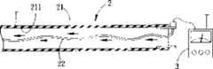
因此有相关业者提出改进方案,参阅图1所示现有呼吸器导管2,具有一导管本体21,并于导管本体21内设置一加热丝22(由高阻抗材料制成),借着一控制装置3操控加热丝22的升温作用,对导管本体21中的气体进行加热。虽然此种呼吸器导管2成功解决供应气体温度过低的问题,但因加热丝22必须放入导管本体21内,又加热丝22与导管本体21的内周面211间缺乏连结或固定,仅于管口处提供接头钳夹,加热丝22无法被有效定位,易发生加热丝22松脱掉落而影响加热效果的情形。Therefore relevant industry has proposed improvement plan, referring to existing
发明内容Contents of the invention
本发明的目的在于提供一种作用与构造皆更加确实的呼吸器导管。The object of the present invention is to provide a respirator catheter with more reliable function and structure.
本发明呼吸器导管包含供气体流通的一中空管体、一肋条,以及一加热单元。其中,该肋条是环绕地设于该管体的外表面。而该加热单元具有一组设于肋条中以对管体中流通气体进行电热加温的电热元件。The respirator conduit of the present invention includes a hollow tube for gas circulation, a rib, and a heating unit. Wherein, the rib is arranged around the outer surface of the tube. The heating unit has a group of electric heating elements arranged in the ribs to electrically heat the gas flowing in the pipe body.
本发明的呼吸器导管可以确保加热作业以几近恒温的状态进行,更在温度过高或过低时灵活调整,确实能达到本发明目的。The respirator conduit of the present invention can ensure that the heating operation is carried out in a nearly constant temperature state, and can be adjusted flexibly when the temperature is too high or too low, which can indeed achieve the purpose of the present invention.
附图说明Description of drawings
下面通过最佳实施例及附图对本发明呼吸器导管进行详细说明,附图中:Below by preferred embodiment and accompanying drawing, respirator catheter of the present invention is described in detail, in the accompanying drawing:
图1是一种现有呼吸器导管的一使用状态示意图。Fig. 1 is a schematic diagram of a use state of a conventional respirator catheter.
图2是一局部侧视示意图,说明本发明呼吸器导管的一较佳实施例。Figure 2 is a schematic partial side view illustrating a preferred embodiment of the respirator catheter of the present invention.
图3是一局部剖视图,说明在该较佳实施例中,一电阻丝被埋设于一肋条中并沿着导管本体呈螺旋状围绕的情形。Fig. 3 is a partial sectional view illustrating that in the preferred embodiment, a resistance wire is embedded in a rib and helically wound along the catheter body.
具体实施方式Detailed ways
如图2及3所示,本发明呼吸器导管1的较佳实施例是与一呼吸器配合使用构成一呼吸治疗设备,该导管1提供一将预定气体由气体供应单元输送至呼吸器的气体输送管路,俾使该预定气体由气体供应单元经由呼吸器供给至使用者的口鼻,为便于说明,图中均未绘示呼吸器及气体供应单元。As shown in Figures 2 and 3, the preferred embodiment of the
以图2为例,呼吸器是设于图中呼吸器导管1的左侧,气体供应单元是设在图中呼吸器导管1的右侧,而气体流动方向则如图3箭头所示。该呼吸器是一种可罩覆在患者口鼻处的面罩,而该气体供应单元则为一供气钢瓶,且于瓶口加设控制气体出入的装置,供应气体多为氧气。Taking Fig. 2 as an example, the respirator is arranged on the left side of the
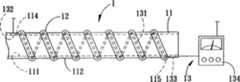
本发明呼吸器导管1的较佳实施例包含:一中空管体11、一肋条12及一加热单元13。该管体11具有一内表面111及一外表面112,该内表面111界定出一供气体单向地由气体供应单元往呼吸器流动的通道113。管体11更具有一邻近呼吸器的使用端114及一邻近气体供应单元相的气体来源端115。A preferred embodiment of the
而该肋条12是沿着管体11的长度方向以螺旋状环绕在该管体11的外表面112,且该螺旋状肋条12沿管体11长度大致呈等间隔分布,以提供沿管体11长度方向的均匀加热作用。The
该加热单元13是利用一可挠细长形电热元件来产生热源以加热通道113中的输送气体,本实施例中,加热单元13包含一组设于肋条12中的电阻丝131(电热元件)、一第一温度感应器132、一第二温度感应器133,以及一控制装置134。The
该第一温度感应器132是电性连接地设置在电阻丝131邻近使用端114处,该第二温度感应器133则电性连结地设于电阻丝131邻近气体来源端115处,控制装置134、第二温度感应器133、电阻丝131与第一温度感应器132形成一个电性回路,此为习于该项技术人士所轻易熟悉,将不另行赘述。The
其中,该管体11与肋条12均由热塑性聚酯弹性体所制成,本实施例系以杜邦公司出产的hytrel(此为杜邦公司注册在案的商标产品)材料制成,若采用硅氧树脂(silicone)亦为可行的取代方案。电阻丝131是包埋在长条形肋条12内后,再固着至预先成型的管体11外表面112,使该包埋电阻丝131的肋条12与管体11形成一体型态。Wherein, the
如图3所示,当气体供应单元开启后,气体便沿着通道113前进(由图中右侧往左侧流动),此时可取舍地由该控制装置134启动电阻丝131的升温作用,在加热同时,该第一温度感应器132可侦测使用端114的气体温度,而第二温度感应器133可侦测气体来源端115的气体温度,所有温度感应器132、133的侦测结果均送回控制装置134并与预设温度比对后进行实时监控。电阻丝131的温度透过管体11材料传导,令通道113内的流动气体受到加热,使得经由呼吸器送入使用者口鼻的气体将是较为接近生理状态的最适温度,借以降低使用者对于低温空气的不适感。As shown in Figure 3, when the gas supply unit is turned on, the gas advances along the channel 113 (flowing from the right side to the left side in the figure), at this time, the
在加热进行同时,二温度感应器132、133皆持续地检验自其旁侧通过的供应气体温度,若其中任一者132或133感应结果显示气体温度过高,则可及时通报控制装置134,由控制装置134调整供应给电阻丝131的电流量,进而改变气体温度。反之,若供应气体温度过高,也能够利用同样的回路系统回报控制装置134,使得经由呼吸器导管1的气体温度能够更精微地被调整,确保进入使用者口鼻部的气体皆能达到最适或恒温状态。While heating, the two
此外,正因为电阻丝131被包埋于肋条12内,又肋条12与管体11为一体成形,整个呼吸器导管1可适用于各种弯折状态,也就是说,该呼吸器导管1能够适切地配合工作环境的需求,进行多种角度的弯折,在肋条12保护之下,电阻丝131不易发生断裂或者是松脱掉落,除确保加热功能得正常进行之外亦能增加其使用寿命。另一方面,本发明的电阻丝131受到肋条12所包覆,故外部发热程度降低,在使用上较安全。In addition, just because the
归纳上述,本发明呼吸器导管1透过将电阻丝131包埋于肋条12中,彻底阻绝电阻丝131散乱或混杂排列的困扰,又肋条12螺旋缠绕于管体11的外表面112,对信道113中的流通气体进行加热,配合温度感应器132、133与控制装置134,确保加热作业以几近恒温的状态进行,更在温度过高或过低时灵活调整,确实能达到本发明目的。To sum up the above, the
Claims (7)
Priority Applications (1)
| Application Number | Priority Date | Filing Date | Title |
|---|---|---|---|
| CN 200510085196CN1899641A (en) | 2005-07-22 | 2005-07-22 | Respirator catheter |
Applications Claiming Priority (1)
| Application Number | Priority Date | Filing Date | Title |
|---|---|---|---|
| CN 200510085196CN1899641A (en) | 2005-07-22 | 2005-07-22 | Respirator catheter |
Publications (1)
| Publication Number | Publication Date |
|---|---|
| CN1899641Atrue CN1899641A (en) | 2007-01-24 |
Family
ID=37655748
Family Applications (1)
| Application Number | Title | Priority Date | Filing Date |
|---|---|---|---|
| CN 200510085196PendingCN1899641A (en) | 2005-07-22 | 2005-07-22 | Respirator catheter |
Country Status (1)
| Country | Link |
|---|---|
| CN (1) | CN1899641A (en) |
Cited By (14)
| Publication number | Priority date | Publication date | Assignee | Title |
|---|---|---|---|---|
| WO2014127666A1 (en)* | 2013-02-21 | 2014-08-28 | 东莞永胜医疗制品有限公司 | Threaded heating pipe and preparation method therefor |
| CN108211077A (en)* | 2018-01-05 | 2018-06-29 | 绍兴安迪斯医疗科技有限公司 | A kind of hot type pipeline and its processing technology |
| CN109091396A (en)* | 2018-09-20 | 2018-12-28 | 南京医科大学附属逸夫医院 | Intelligent enteral nutrition feeds constant-temperature heating system |
| CN109568744A (en)* | 2018-11-16 | 2019-04-05 | 泗水县人民医院 | A kind of Pediatric Clinic breathing equipment with uninterrupted regulatory function |
| CN112156296A (en)* | 2020-09-08 | 2021-01-01 | 绍兴安迪斯医疗科技有限公司 | Novel outer wall heating breathing pipeline |
| CN113143580A (en)* | 2021-04-07 | 2021-07-23 | 深圳市眼科医院 | Pen type delicate freezing device adopting Freon |
| CN116407720A (en)* | 2021-12-31 | 2023-07-11 | 天津怡和嘉业医疗科技有限公司 | Airflow Delivery Devices and Breathing Devices |
| US12053587B2 (en) | 2012-11-14 | 2024-08-06 | Fisher & Paykel Healthcare Limited | Zone heating for respiratory circuits |
| US12076489B2 (en) | 2016-12-22 | 2024-09-03 | Fisher & Paykel Healthcare Limited | Medical tubes and methods of manufacture |
| US12233212B2 (en) | 2015-09-09 | 2025-02-25 | Fisher & Paykel Healthcare Limited | Zone heating for respiratory circuits |
| US12246132B2 (en) | 2014-03-17 | 2025-03-11 | Fisher & Paykel Healthcare Limited | Medical tubes for respiratory systems |
| US12280215B2 (en) | 2011-06-03 | 2025-04-22 | Fisher & Paykel Healthcare Limited | Medical tubes and methods of manufacture |
| US12296102B2 (en) | 2012-12-04 | 2025-05-13 | Fisher & Paykel Healthcare Limited | Medical tubes and methods of manufacture |
| US12364837B2 (en) | 2013-10-24 | 2025-07-22 | Fisher & Paykel Healthcare Limited | Tubing for delivery of respiratory gases |
- 2005
- 2005-07-22CNCN 200510085196patent/CN1899641A/enactivePending
Cited By (14)
| Publication number | Priority date | Publication date | Assignee | Title |
|---|---|---|---|---|
| US12280215B2 (en) | 2011-06-03 | 2025-04-22 | Fisher & Paykel Healthcare Limited | Medical tubes and methods of manufacture |
| US12053587B2 (en) | 2012-11-14 | 2024-08-06 | Fisher & Paykel Healthcare Limited | Zone heating for respiratory circuits |
| US12296102B2 (en) | 2012-12-04 | 2025-05-13 | Fisher & Paykel Healthcare Limited | Medical tubes and methods of manufacture |
| WO2014127666A1 (en)* | 2013-02-21 | 2014-08-28 | 东莞永胜医疗制品有限公司 | Threaded heating pipe and preparation method therefor |
| US12364837B2 (en) | 2013-10-24 | 2025-07-22 | Fisher & Paykel Healthcare Limited | Tubing for delivery of respiratory gases |
| US12246132B2 (en) | 2014-03-17 | 2025-03-11 | Fisher & Paykel Healthcare Limited | Medical tubes for respiratory systems |
| US12233212B2 (en) | 2015-09-09 | 2025-02-25 | Fisher & Paykel Healthcare Limited | Zone heating for respiratory circuits |
| US12076489B2 (en) | 2016-12-22 | 2024-09-03 | Fisher & Paykel Healthcare Limited | Medical tubes and methods of manufacture |
| CN108211077A (en)* | 2018-01-05 | 2018-06-29 | 绍兴安迪斯医疗科技有限公司 | A kind of hot type pipeline and its processing technology |
| CN109091396A (en)* | 2018-09-20 | 2018-12-28 | 南京医科大学附属逸夫医院 | Intelligent enteral nutrition feeds constant-temperature heating system |
| CN109568744A (en)* | 2018-11-16 | 2019-04-05 | 泗水县人民医院 | A kind of Pediatric Clinic breathing equipment with uninterrupted regulatory function |
| CN112156296A (en)* | 2020-09-08 | 2021-01-01 | 绍兴安迪斯医疗科技有限公司 | Novel outer wall heating breathing pipeline |
| CN113143580A (en)* | 2021-04-07 | 2021-07-23 | 深圳市眼科医院 | Pen type delicate freezing device adopting Freon |
| CN116407720A (en)* | 2021-12-31 | 2023-07-11 | 天津怡和嘉业医疗科技有限公司 | Airflow Delivery Devices and Breathing Devices |
Similar Documents
| Publication | Publication Date | Title |
|---|---|---|
| US12296102B2 (en) | Medical tubes and methods of manufacture | |
| CN1899641A (en) | Respirator catheter | |
| AU2003200559B2 (en) | Conduit Overheating Detection System | |
| US6167883B1 (en) | Medical air hose internal flow heater | |
| CN1230222C (en) | Humidifier for respiratory system | |
| EP1542756B1 (en) | Humidification system | |
| CN1230221C (en) | Humidity controller | |
| CN103842013B (en) | Snorkel system | |
| JP2004511309A (en) | Equipment used to humidify gas in medical procedures | |
| AU2016290890B2 (en) | Device and system for heating respiratory conduit | |
| AU2007216906A1 (en) | High flow respirator circuit | |
| CN113164705A (en) | Line heat pipe for breathing equipment | |
| TWI289066B (en) | Conduit of a respirator | |
| JP2006271953A (en) | Tube heating device for air supply or liquid supply | |
| US20250319274A1 (en) | Medical tubes and methods of manufacture | |
| KR101253986B1 (en) | A circuit for medical | |
| AU5354400A (en) | Medical air hose having internal flow heater |
Legal Events
| Date | Code | Title | Description |
|---|---|---|---|
| C06 | Publication | ||
| PB01 | Publication | ||
| C10 | Entry into substantive examination | ||
| SE01 | Entry into force of request for substantive examination | ||
| C02 | Deemed withdrawal of patent application after publication (patent law 2001) | ||
| WD01 | Invention patent application deemed withdrawn after publication |