CN1888386A - Strapdown inertial combine measurement controller adapted to whole-optical fiber digital slope level - Google Patents
Strapdown inertial combine measurement controller adapted to whole-optical fiber digital slope levelDownload PDFInfo
- Publication number
- CN1888386A CN1888386ACN 200610089775CN200610089775ACN1888386ACN 1888386 ACN1888386 ACN 1888386ACN 200610089775CN200610089775CN 200610089775CN 200610089775 ACN200610089775 ACN 200610089775ACN 1888386 ACN1888386 ACN 1888386A
- Authority
- CN
- China
- Prior art keywords
- information
- measurement
- msub
- output
- mtr
- Prior art date
- Legal status (The legal status is an assumption and is not a legal conclusion. Google has not performed a legal analysis and makes no representation as to the accuracy of the status listed.)
- Granted
Links
Images

Landscapes
- Navigation (AREA)
- Gyroscopes (AREA)
Abstract
Translated fromChineseDescription
Translated fromChinese技术领域technical field
本发明涉及一种提高全光纤数字测斜仪测量精度的信息处理控制装置,更特别地说,是指一种利用外部多传感器采集的传感信息与光纤陀螺采集的惯性信息进行信息融合处理,该捷联惯性组合测量控制装置能够有效地提高全光纤数字测斜仪长时间工作的测量精度。The present invention relates to an information processing control device for improving the measurement accuracy of an all-fiber digital inclinometer, more particularly, it refers to an information fusion process using sensing information collected by external multi-sensors and inertial information collected by an optical fiber gyroscope, The strapdown inertial combination measurement control device can effectively improve the measurement accuracy of the all-fiber digital inclinometer working for a long time.
背景技术Background technique
随着石油资源的贫化,开采的难度越来越大。在石油钻采的过程中,迫切需要能够精确测量井眼轨迹参数的高精度测斜仪器为工业部门提供可靠的设计、开发信息。尤其是对于超深井,当发生深的高压地层井喷事件时,需要根据精确的井眼轨迹钻减压井来终止井喷。此外,现代钻采技术的发展,使随钻测量(MWD)成为现实,理想测斜仪是能在钻头钻进的过程中实时监测和显示钻头的位置,以便于操作人员及时调整钻头,使其按预先设计轨迹达到目标靶区。这都需要有高精度的井眼轨迹测量仪器。With the depletion of oil resources, it is more and more difficult to extract. In the process of oil drilling, there is an urgent need for high-precision inclinometers that can accurately measure wellbore trajectory parameters to provide reliable design and development information for industrial departments. Especially for ultra-deep wells, when blowout events occur in deep high-pressure formations, it is necessary to drill relief wells according to precise well trajectory to terminate the blowout. In addition, the development of modern drilling technology has made measurement while drilling (MWD) a reality. The ideal inclinometer can monitor and display the position of the drill bit in real time during the drilling process, so that the operator can adjust the drill bit in time to make it Reach the target target area according to the pre-designed trajectory. All of these require high-precision borehole trajectory measurement instruments.
目前,在石油工业领域使用的此类测斜仪器主要是由磁通门传感器或机械陀螺作为角速度传感器与加速度计结合,测量井眼的方位角和井斜角。磁通门式测斜仪具有结构简单、价格低、性能稳定的优点,但其无法实现对有磁性干扰的被测油井进行的井眼轨迹测量;而机械陀螺式测斜仪可弥补这一缺憾,但机械陀螺内部固有的转动机构使其存在着结构复杂、易损坏、抗振性差、漂移大等缺陷。At present, such inclinometers used in the petroleum industry mainly use fluxgate sensors or mechanical gyroscopes as angular velocity sensors combined with accelerometers to measure the azimuth and inclination of boreholes. The fluxgate inclinometer has the advantages of simple structure, low price and stable performance, but it cannot realize the wellbore trajectory measurement of the measured oil well with magnetic interference; the mechanical gyro inclinometer can make up for this shortcoming , but the inherent rotation mechanism inside the mechanical gyroscope makes it have defects such as complex structure, easy damage, poor vibration resistance, and large drift.
全光纤数字测斜仪是一种基于光纤陀螺捷联惯性测量原理的井眼轨迹测量仪器,由于光纤陀螺和加速度计组成的惯性测量误差会随时间的增长而增大,导致了测斜仪在长时间工作环境下的测量精度较低,难以满足石油测井实际使用时长时间的高精度测量要求。根据惯性测量模式在短时间具有高精度的优点并结合石油、天然气测井作业的实际工作环境和工作条件,本发明专利申请提出了一种适用于全光纤数字测斜仪的捷联惯性组合测量控制装置。The all-fiber digital inclinometer is a borehole trajectory measurement instrument based on the principle of fiber optic gyro strapdown inertial measurement. Since the inertial measurement error composed of fiber optic gyro and accelerometer will increase with time, the inclinometer The measurement accuracy in the long-time working environment is low, and it is difficult to meet the long-term high-precision measurement requirements in the actual use of petroleum logging. According to the advantages of high precision in a short time in the inertial measurement mode and combined with the actual working environment and working conditions of oil and natural gas logging operations, the patent application of the present invention proposes a strapdown inertial combination measurement suitable for all-fiber digital inclinometers control device.
发明内容Contents of the invention
本发明是一种适用于全光纤数字测斜仪的捷联惯性组合测量控制装置,该捷联惯性组合测量控制装置,采用磁通门测量信息、有线测井时的缆长信息以及下井探管停止时的零速信息分别与捷联惯性测量输出的下井探管的姿态信息和速度信息进行比较,得到差值信号;然后将所述差值信号作为KALMAN滤波器的观测量进行多种测量信息数据融合获得补偿信号,所述补偿信号用于对捷联惯性测量产生的误差信息进行估计和在线修正,限制捷联惯性测量的误差发散,从而实现了全光纤数字测斜仪长时间工作的高精度测量。The present invention is a strapdown inertial combination measurement control device suitable for all-fiber digital inclinometers. The strapdown inertial combination measurement control device uses fluxgate measurement information, cable length information during wired well logging, and downhole probes. The zero-speed information when stopped is compared with the attitude information and speed information of the downhole probe output by the strapdown inertial measurement to obtain a difference signal; then the difference signal is used as the observation of the KALMAN filter to perform various measurement information The compensation signal is obtained by data fusion, and the compensation signal is used to estimate and correct the error information generated by the strapdown inertial measurement and limit the error divergence of the strapdown inertial measurement. Accuracy measurement.
本发明是一种适用于全光纤数字测斜仪的捷联惯性组合测量控制装置,包括:The invention is a strapdown inertial combination measurement control device suitable for all-fiber digital inclinometers, comprising:
用于存储惯性组合测量任务控制程序的计算机;A computer for storing the IIM mission control program;
用于输入角速度信息的光纤陀螺;Fiber optic gyroscope for inputting angular velocity information;
用于输入比力信息的加速度计;Accelerometer for input of specific force information;
用于输入地磁分量信息的磁通门;A fluxgate for inputting geomagnetic component information;
用于输入零速修正信息的下井探管;Downhole probe for entering zero-speed correction information;
用于输入缆长信息的计数器,计数器安装在光缆绞盘上,光缆的一端连接在光缆绞盘上,另一端固定在下井探管上;还包括:A counter for inputting cable length information, the counter is installed on the optical cable winch, one end of the optical cable is connected to the optical cable winch, and the other end is fixed on the downhole probe; it also includes:
捷联惯性测量、磁测量、光缆运行速度测量、卡尔曼滤波器和信息比较A单元、信息比较B单元、信息比较C单元,Strapdown inertial measurement, magnetic measurement, optical cable running speed measurement, Kalman filter and information comparison A unit, information comparison B unit, information comparison C unit,
所述捷联惯性测量首先接收 A)所述光纤陀螺输出的下井探管机体坐标系ObXbYbZb下的角速度信息;和The strapdown inertial measurement first receives A) the angular velocity information under the downhole probe body coordinate system Ob Xb Yb Zb output by the fiber optic gyroscope; and
B)所述加速度计输出的下井探管机体坐标系ObXbYbZb下的比力信息;然后对B) the specific force information under the downhole probe body coordinate system Ob Xb Yb Zb of described accelerometer output; Then to
所述角速度信息和所述比力信息采用航迹推算处理后,输出 C)下井探管的速度信息Vx、Vy、Vz;和After the angular velocity information and the specific force information are processed by dead reckoning, output C) the velocity information Vx , Vy , Vz of the downhole probe; and
D)下井探管姿态信息的方位角ψ、横滚角φ、倾斜角θ;最后
将E)所述速度信息Vx、Vy、Vz输出给所述信息比较B单元和所述信息比较C单元;E) outputting the speed information Vx , Vy , Vz to the information comparing unit B and the information comparing unit C;
将F)所述姿态信息输出给信息比较A单元;The attitude information of F) is output to the information comparison unit A;
所述磁通门测量首先接收A)磁通门组件输出的下井探管机体坐标系ObXbYbZb下的地磁分量信息;和The fluxgate measurement first receives A) the geomagnetic component information under the downhole probe body coordinate system Ob Xb Yb Zb output by the fluxgate assembly; and
B)加速度计输出的下井探管机体坐标系ObXbYbZb下的比力信息;然后对B) the specific force information under the body coordinate system Ob Xb Yb Zb of the downhole probe output by the accelerometer;
所述地磁分量信息和所述比力信息采用磁测量计算,并将计算出的相对于磁北的方位角转换为相对于真北的方位角ψc后,输出所述下井探管姿态信息的方位角ψc、横滚角φc、倾斜角θc;最后The geomagnetic component information and the specific force information are calculated by magnetic measurement, and the calculated azimuth relative to magnetic north is converted into an azimuth ψc relative to true north, and the azimuth of the downhole probe attitude information is output angle ψc , roll angle φc , bank angle θc ; finally
将C)所述姿态信息输出给信息比较A单元;C) the posture information is output to the information comparison unit A;
所述光缆运行速度测量是采用所述计数器测量得到的光缆长度在单位时间内光缆长度增量得到下井探管运行时在其机体坐标系ObXbYbZb下的速度信息;The optical cable running speed measurement is to use the optical cable length measured by the counter to obtain the speed information of the optical cable length increment per unit time under the body coordinate system Ob Xb Yb Zb when the downhole probe is running;
所述卡尔曼滤波器接收The Kalman filter receives
A)信息比较A单元输出的姿态差值
B)信息比较B单元输出的速度差值
C)信息比较C单元输出的速度差值
利用离散型卡尔曼滤波器对接收信息进行数据融合实现对状态变量Using the discrete Kalman filter to perform data fusion on the received information to realize the state variable
X=[δrx,δry,δrz,δvy,δvz,ηx,ηy,ηz,δfx,δfy,δfz,δωx,δωy,δωz]的进行最优估计,根据估计的状态变量对所述捷联惯性测量进行在线误差补偿,输出补偿后的下井探管姿态信息
所述信息比较A单元,用于完成对所述捷联惯性测量输出的下井探管姿态信息的方位角ψ、横滚角φ、倾斜角θ与所述磁测量输出的下井探管姿态信息的方位角ψc、横滚角φc、倾斜角θc相减输出姿态差值
所述信息比较B单元,用于完成对所述捷联惯性测量输出的下井探管的速度信息Vx、Vy、Vz与所述光缆运动速度测量输出的速度信息Vxc、Vyc、Vzc相减输出速度差值
所述信息比较C单元,用于完成对所述捷联惯性测量输出的下井探管的速度信息Vx、Vy、Vz与所述下井探管静止量输出的零速度信息相减输出速度差值
所述的捷联惯性组合测量控制装置,其具有捷联惯性测量+缆长的第一测量工作模式、或者捷联惯性测量+零速修正的第二测量工作模式、或者捷联惯性测量+磁测量的第三测量工作模式、或者捷联惯性测量+缆长+零速修正+磁测量的第四测量工作模式。The strapdown inertial combination measurement control device has a first measurement mode of strapdown inertial measurement + cable length, or a second measurement mode of strapdown inertial measurement + zero speed correction, or a strapdown inertial measurement + magnetic The third measurement working mode of measurement, or the fourth measurement working mode of strapdown inertial measurement + cable length + zero speed correction + magnetic measurement.
本发明捷联惯性组合测量控制装置的优点在于:(1)多种测量模式的灵活切换,操作方便;(2)多种测量模式的使用为测斜仪提供了广阔的使用空间;(3)多传感器组件的同时使用,提高了测斜仪的使用可靠性;(4)对多传感器组件进行信息融合可有效提高测斜仪的测量精度,能够在使用中等精度惯性测量器件(光纤陀螺和加速度计)条件下实现高精度的组合测量系统,降低了测斜仪的加工成本。The advantages of the strapdown inertial combination measurement control device of the present invention are: (1) flexible switching of multiple measurement modes and convenient operation; (2) the use of multiple measurement modes provides a wide use space for the inclinometer; (3) The simultaneous use of multi-sensor components improves the reliability of the inclinometer; (4) information fusion of multi-sensor components can effectively improve the measurement accuracy of the inclinometer, and can be used in the use of medium-precision inertial measurement devices (optical fiber gyroscope and acceleration A high-precision combined measurement system is realized under the condition of meter), which reduces the processing cost of the inclinometer.
附图说明Description of drawings
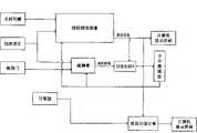
图1是本发明捷联惯性组合测量控制装置的结构框图。Fig. 1 is a structural block diagram of the strapdown inertial combination measurement control device of the present invention.
图2是信息测量切换为缆长信息与捷联惯性测量系统的结构框图。Fig. 2 is a structural block diagram of switching from information measurement to cable length information and strapdown inertial measurement system.
图3是信息测量切换为下井探管停止时零速信息与捷联惯性测量系统的结构框图。Fig. 3 is a structural block diagram of the zero-speed information and the strapdown inertial measurement system when the information measurement is switched to the stop of the downhole probe.
图4是信息测量切换为磁通门与捷联惯性测量系统的结构框图。Fig. 4 is a structural block diagram of information measurement switched to fluxgate and strapdown inertial measurement system.
图5是捷联惯性组合测量控制装置的主控界面示意图。Fig. 5 is a schematic diagram of the main control interface of the strapdown inertial combination measurement control device.
具体实施方式Detailed ways
下面将结合附图本发明作进一步的详细说明。The present invention will be described in further detail below in conjunction with accompanying drawing.
本发明是一种适用于全光纤数字测斜仪的捷联惯性组合测量控制装置,是对捷联惯性测量输出的姿态信息、速度信息分别与磁测量输出的磁姿态信息、光缆绞盘运动的速度信息和下井探管静止时的零速信息进行信息比较后,并对所述信息比较输出的差值进行卡尔曼滤波处理后,用于估计捷联惯性组合的相关误差并进行修正和补偿。经所述修正和补偿后的捷联惯性测量将输出的姿态信息给计算机进行精确的井眼轨迹绘图及显示。The invention is a strapdown inertial combined measurement control device suitable for all-fiber digital inclinometers, which is used to separate the attitude information and speed information output by strapdown inertial measurement from the magnetic attitude information output by magnetic measurement and the speed of optical cable winch movement. After the information is compared with the zero-speed information when the downhole probe is stationary, and the difference outputted by the information comparison is processed by Kalman filter, it is used to estimate the relevant error of the strapdown inertial combination and perform correction and compensation. The corrected and compensated strapdown inertial measurement sends the output attitude information to the computer for accurate wellbore trajectory drawing and display.
全光纤数字测斜仪由公知计算机、捷联惯性组合测量控制程序、信号采集器、光缆铰盘、井架和下井探管组成,捷联惯性组合测量控制程序存储于计算机的存储器中,信号采集器安装于计算机的主板插槽上,信号采集器与光缆铰盘采用有线连接,光缆铰盘上的光缆一端与下井探管连接,光缆在井架上滑动实现将下井探管放入井眼中。The all-fiber digital inclinometer is composed of a known computer, a strapdown inertial combination measurement control program, a signal collector, an optical cable reamer, a derrick and a downhole probe. The strapdown inertial combination measurement control program is stored in the memory of the computer, and the signal collector Installed on the motherboard slot of the computer, the signal collector and the optical cable reel are connected by wire, and one end of the optical cable on the optical cable reel is connected to the downhole probe, and the optical cable slides on the derrick to put the downhole probe into the wellbore.
参见图1所示,本发明捷联惯性组合测量控制装置包括捷联惯性测量、磁通门测量、光缆运行速度测量、卡尔曼滤波处理、三个信息比较模块(信息比较A、信息比较B和信息比较C)和零速修正模块(下井探管静止时信息),下面将从各部分能够实现的功能进行说明。Referring to shown in Figure 1, the strapdown inertial combination measurement control device of the present invention comprises strapdown inertial measurement, fluxgate measurement, optical cable running speed measurement, Kalman filter processing, three information comparison modules (information comparison A, information comparison B and Information comparison C) and zero-speed correction module (information when the downhole probe is at rest), the functions that can be realized by each part will be described below.
一、捷联惯性测量1. Strapdown inertial measurement
惯性测量分为平台式惯性测量和捷联式惯性测量,捷联式惯性测量是将陀螺和加速度计直接固连在机体上的一种惯性测量方式。捷联式惯性测量是用数学平台取代平台式惯性测量中的物理平台而进行的一种测量模式。该捷联式惯性测量具有机械结构简单、尺寸小、相对造价较低,但由于陀螺和加速度计直接固连在机体上,导致陀螺和加速度计的输入动态范围较大,则在对使用合适的陀螺和加速度计提出了更高的要求,此外选用数学平台代替物理平台对数据处理用的计算机要求较高。Inertial measurement is divided into platform inertial measurement and strapdown inertial measurement. Strapdown inertial measurement is an inertial measurement method that directly connects the gyroscope and accelerometer to the body. Strapdown inertial measurement is a measurement mode that replaces the physical platform in platform inertial measurement with a mathematical platform. The strapdown inertial measurement has a simple mechanical structure, small size, and relatively low cost. However, since the gyroscope and the accelerometer are directly connected to the body, the input dynamic range of the gyroscope and the accelerometer is relatively large. Gyroscopes and accelerometers put forward higher requirements. In addition, choosing a mathematical platform instead of a physical platform requires a higher computer for data processing.
在本发明中,捷联惯性测量首先接收A)光纤陀螺输出的下井探管机体坐标系ObXbYbZb下的角速度信息;和B)加速度计输出的下井探管机体坐标系ObXbYbZb下的比力信息;然后对所述角速度信息和所述比力信息采用航迹推算处理后,输出C)下井探管的速度信息Vx、Vy、Vz;和D)下井探管姿态信息的方位角ψ、横滚角φ、倾斜角θ;最后,将E)所述速度信息Vx、Vy、Vz输出给信息比较B单元和信息比较C单元;将F)所述姿态信息输出给信息比较A单元。In the present invention, the strapdown inertial measurement first receives A) the angular velocity information under the downhole probe body coordinate system Ob Xb Yb Zb output by the fiber optic gyroscope; and B) the downhole probe body coordinate system O output by the accelerometer The specific force information underb Xb Yb Zb ; then, after the angular velocity information and the specific force information are processed by dead reckoning, output C) the velocity information Vx , Vy , Vz of the downhole probe; and D) the azimuth ψ, roll angle φ, and inclination θ of the downhole probe attitude information; finally, output the velocity information Vx , Vy , and Vz described in E) to the information comparison unit B and the information comparison unit C ; Output F) the posture information to the information comparison A unit.
卡尔曼滤波器输出的所述状态变量X用于在线补偿所述捷联惯性测量的误差,其补偿后的表示下井探管姿态信息的输出为方位角ψ0、横滚角φ0、倾斜角θ0。并将这些姿态信息输出给计算机显示界面(参见图5所示)上绘图显示(井眼轨迹绘制),以方便操作者实时监测。The state variable X output by the Kalman filter is used to compensate the error of the strapdown inertial measurement online, and the output after the compensation represents the attitude information of the downhole probe is the azimuth ψ0 , the roll angle φ0 , the inclination angle θ0 . And output these posture information to the computer display interface (see Fig. 5) for drawing display (wellbore trajectory drawing), so as to facilitate real-time monitoring by the operator.
垂直井深计算单元用于计算井眼的垂直井深,并将井深参数输出给计算机显示界面显示,以方便操作者实时监测。垂直井深计算单元的井深计算是通过将接收的缆长信息与下井探管倾斜角θ0的余弦相乘得到被测点的垂直井深。The vertical well depth calculation unit is used to calculate the vertical well depth of the borehole, and output the well depth parameters to the computer display interface for real-time monitoring by the operator. The well depth calculation of the vertical well depth calculation unit is to obtain the vertical well depth of the measured point by multiplying the received cable length information with the cosine of the inclination angle θ0 of the downhole probe.
二、磁通门测量2. Fluxgate measurement
磁通门现象是一种普遍存在的电磁感应现象,它是利用高导磁材料在传感器线圈系统中的磁饱和特性而测量磁场的仪器,是应用最广泛的弱磁测量仪器之一,其测量范围为10-12~10-3T,这种仪器结构简单、体积小、重量轻、功耗低、抗震性好、测量范围宽、灵敏度高、分辨率高、稳定性好、适于测量恒定磁场或缓慢变化的磁场。The fluxgate phenomenon is a ubiquitous electromagnetic induction phenomenon. It is an instrument that uses the magnetic saturation characteristics of high magnetic permeability materials in the sensor coil system to measure the magnetic field. It is one of the most widely used weak magnetic measuring instruments. Its measurement The range is 10-12 ~10-3 T. This instrument has simple structure, small size, light weight, low power consumption, good shock resistance, wide measurement range, high sensitivity, high resolution, good stability, and is suitable for measuring constant A magnetic field or a slowly changing magnetic field.
在本发明中,磁通门组件包括三个正交安置的磁通门,即X轴磁通门、Y轴磁通门和Z轴磁通门。In the present invention, the fluxgate assembly includes three fluxgates arranged orthogonally, namely an X-axis fluxgate, a Y-axis fluxgate and a Z-axis fluxgate.
在本发明中,磁通门测量首先接收A)磁通门组件输出的下井探管机体坐标系ObXbYbZb下的地磁分量信息;和B)加速度计输出的下井探管机体坐标系ObXbYbZb下的比力信息;然后对所述地磁分量信息和所述比力信息采用磁测量计算,并将计算出的相对于磁北的方位角转换为相对于真北的方位角ψc后,输出下井探管姿态信息的方位角ψc、横滚角φc、倾斜角θc;最后将C)所述姿态信息输出给信息比较A单元。In the present invention, the fluxgate measurement first receives A) the geomagnetic component information of the downhole probe body coordinate system Ob Xb Yb Zb output by the fluxgate assembly; and B) the downhole probe body output by the accelerometer The specific force information under the coordinate system Ob Xb Yb Zb ; Then the magnetic measurement calculation is adopted for the geomagnetic component information and the specific force information, and the calculated azimuth relative to the magnetic north is converted into relative to the true After the north azimuth ψc , output the azimuth ψc , roll angle φc , and inclination θc of the attitude information of the downhole probe; finally output the attitude information in C) to the information comparison unit A.
三、光缆运行速度3. Optical cable running speed
光缆的一端连接在光缆绞盘上,另一端固定在下井探管上。在本发明中,对下井探管在井中运行的速度可通过计数器测量得到的光缆长度在单位时间内光缆长度增量得到下井探管运行时在其机体坐标系ObXbYbZb下的速度信息。One end of the optical cable is connected to the optical cable winch, and the other end is fixed on the downhole probe. In the present invention, the speed of the downhole probe running in the well can be obtained by measuring the length of the optical cable obtained by the counter. The length increment of the optical cable per unit time is obtained when the downhole probe is running under its body coordinate system Ob Xb Yb Zb speed information.
全光纤数字测斜仪在测量过程中涉及两个坐标系,一个是当地地理坐标系OtXtYtZt,一个是下井探管机体坐标系ObXbYbZb。这两个坐标系存在的坐标转换关系为
下井探管机体坐标系ObXbYbZb与当地地理坐标系OtXtYtZt之间的转换矩阵为
四、卡尔曼滤波器4. Kalman filter
卡尔曼滤波器接收Kalman filter reception
A)信息比较A单元输出的姿态差值
B)信息比较B单元输出的速度差值
C)信息比较C单元输出的速度差值
信息进行数据融合实现对状态变量X=[δrx,δry,δrz,δvx,δvy,δvz,ηx,ηy,ηz,δfx,δfy,δfz,δωx,δωy,δωz]的进行最优估计,根据估计的状态变量对所述捷联惯性测量进行在线误差补偿,输出补偿后的下井探管姿态信息
本发明中的卡尔曼滤波器的滤波处理采用离散型卡尔曼滤波基本方程,其各状态变量初值均设为零。The filter processing of the Kalman filter in the present invention adopts the discrete Kalman filter basic equation, and the initial values of each state variable are all set to zero.
五、信息比较5. Information comparison
在本发明中,信息比较由信息比较A单元、信息比较B单元和信息比较C单元组成,其中,In the present invention, information comparison is composed of information comparison A unit, information comparison B unit and information comparison C unit, wherein,
信息比较A单元,用于完成对所述捷联惯性测量输出的下井探管姿态信息的方位角ψ、横滚角φ、倾斜角θ与所述磁测量输出的下井探管姿态信息的方位角ψc、横滚角φc、倾斜角θc相减输出姿态差值
信息比较B单元,用于完成对所述捷联惯性测量输出的下井探管的速度信息Vx、Vy、Vz与所述光缆运动速度测量输出的速度信息Vxc、Vyc、Vzc相减输出速度差值
信息比较C单元,用于完成对所述捷联惯性测量输出的下井探管的速度信息Vx、Vy、Vz与所述下井探管静止量输出的零速度信息相减输出速度差值
六、零速修正6. Zero speed correction
零速修正是指全光纤数字测斜仪中下井探管处于静止位置时,其速度为零的现象来修正捷联惯性测量输出的速度误差。该“零速修正”通过设置的一按键实现,参见图5所示。采用所述零速修正模式时,下井探管实际的运行速度为零作为输出给信息比较C单元的比较信息。Zero-speed correction refers to the phenomenon that when the downhole probe in the all-fiber digital inclinometer is in a static position, its speed is zero to correct the speed error output by the strapdown inertial measurement. The "zero speed correction" is realized by setting a button, as shown in Fig. 5 . When the zero-speed correction mode is adopted, the actual running speed of the downhole probe is zero as the comparison information output to the information comparison unit C.
本发明捷联惯性组合测量控制装置可以提供四种组合测量工作模式,各个模式通过在图5的界面中按下相应的键实现。其中,The strapdown inertial combined measurement control device of the present invention can provide four combined measurement working modes, and each mode can be realized by pressing a corresponding key in the interface shown in FIG. 5 . in,
模式一:捷联惯性测量+缆长(测量模式中按键设定为①)Mode 1: Strapdown inertial measurement + cable length (set the button to ① in the measurement mode)
该组合测量模式用于常规有线测井的快速连续测量,尤其适用于套管井或有磁性物质干扰的井眼轨迹测量。其结构参见图2所示This combined measurement mode is used for rapid and continuous measurement of conventional wireline logging, especially for cased hole or borehole trajectory measurement with magnetic material interference. Its structure is shown in Figure 2
组合测量所需的信息流程为:第一路信息,捷联惯性测量首先接收A)光纤陀螺输出的下井探管机体坐标系ObXbYbZb下的角速度信息;和B)加速度计输出的下井探管机体坐标系ObXbYbZb下的比力信息;然后对所述角速度信息和所述比力信息采用航迹推算处理后,输出C)下井探管的速度信息Vx、Vy、Vz;最后将所述速度信息Vx、Vy、Vz输出给信息比较B单元。第二路信息,通过计数器对光缆缆长的记录,再经坐标转换获得的表示井下探管的运行速度信息Vxc、Vyc、Vzc输出给信息比较B单元。在信息比较B单元中第一路信息与第二路信息进行速度差值比较后输出给卡尔曼滤波器处理。第三路信息,经卡尔曼滤波输出的所述状态变量X用于在线补偿所述捷联惯性测量的误差,其补偿后表示下井探管姿态信息的输出为方位角ψ0、横滚角φ0、倾斜角θ0。所述姿态信息输出给计算机显示界面绘图显示,以方便操作者实时监测。第四路信息,所述姿态信息输出给垂直井深计算单元进行垂直井深计算,并输出井深参数给计算机显示界面显示,以方便操作者实时监测。The information flow required for combined measurement is: the first channel of information, the strapdown inertial measurement first receives A) the angular velocity information of the downhole probe body coordinate system Ob Xb Yb Zb output by the fiber optic gyroscope; and B) the accelerometer The specific force information under the body coordinate system Ob Xb Yb Zb of the output downhole probe body; then after the angular velocity information and the specific force information are processed by dead reckoning, output C) the speed information of the downhole probe Vx , Vy , Vz ; finally output the speed information Vx , Vy , Vz to the information comparison unit B. The second channel of information is the information Vxc , Vyc , and Vzc obtained through the coordinate transformation of the optical cable length recorded by the counter and representing the running speed of the downhole probe, and output to the information comparison unit B. In the information comparison unit B, the speed difference between the first information and the second information is compared and then output to the Kalman filter for processing. The third information, the state variable X output by Kalman filter is used to compensate the error of the strapdown inertial measurement online, after compensation, the output of the downhole probe attitude information is the azimuth ψ0 , roll angle φ0 , inclination angle θ0 . The posture information is output to the computer display interface for graphic display, so as to facilitate real-time monitoring by the operator. The fourth information, the attitude information is output to the vertical well depth calculation unit for vertical well depth calculation, and the well depth parameters are output to the computer display interface for display, so as to facilitate real-time monitoring by the operator.
模式二:捷联惯性测量+零速修正(测量模式中按键设定为②)Mode 2: Strapdown inertial measurement + zero speed correction (set the button to ② in the measurement mode)
该组合测量模式用于不要求连续测量的测井过程中,可用在随钻测井(MWD)过程中,实时监测钻头的钻进方向。其结构参见图3所示This combined measurement mode is used in the logging process that does not require continuous measurement, and can be used in the logging while drilling (MWD) process to monitor the drilling direction of the drill bit in real time. Its structure is shown in Figure 3
组合测量所需的信息流程为:第一路信息,捷联惯性测量首先接收A)光纤陀螺输出的下井探管机体坐标系ObXbYbZb下的角速度信息;和B)加速度计输出的下井探管机体坐标系ObXbYbZb下的比力信息;然后对所述角速度信息和所述比力信息采用航迹推算处理后,输出C)下井探管的速度信息Vx、Vy、Vz;最后将所述速度信息Vx、Vy、Vz输出给信息比较C单元。第二路信息,下井探管实际的运行速度为零作为输出给信息比较C单元的比较信息。在信息比较C单元中第一路信息与第二路信息进行速度差值比较后输出给卡尔曼滤波器处理。第三路信息,经卡尔曼滤波输出的所述状态变量X用于在线补偿所述捷联惯性测量的误差,其补偿后表示下井探管姿态信息的输出为方位角ψ0、横滚角φ0、倾斜角θ0。所述姿态信息输出给计算机显示界面绘图显示,以方便操作者实时监测。第四路信息,所述姿态信息输出给垂直井深计算单元进行垂直井深计算,并输出井深参数给计算机显示界面显示,以方便操作者实时监测。The information flow required for combined measurement is: the first channel of information, the strapdown inertial measurement first receives A) the angular velocity information of the downhole probe body coordinate system Ob Xb Yb Zb output by the fiber optic gyroscope; and B) the accelerometer The specific force information under the body coordinate system Ob Xb Yb Zb of the output downhole probe body; then after the angular velocity information and the specific force information are processed by dead reckoning, output C) the speed information of the downhole probe Vx , Vy , Vz ; finally output the speed information Vx , Vy , Vz to the information comparison C unit. The second information, the actual running speed of the downhole probe is zero as the comparison information output to the information comparison unit C. In the information comparison unit C, the speed difference between the first information and the second information is compared and then output to the Kalman filter for processing. The third information, the state variable X output by Kalman filter is used to compensate the error of the strapdown inertial measurement online, after compensation, the output of the downhole probe attitude information is the azimuth ψ0 , roll angle φ0 , inclination angle θ0 . The posture information is output to the computer display interface for graphic display, so as to facilitate real-time monitoring by the operator. The fourth information, the attitude information is output to the vertical well depth calculation unit for vertical well depth calculation, and the well depth parameters are output to the computer display interface for display, so as to facilitate real-time monitoring by the operator.
模式三:捷联惯性测量+磁测量(测量模式中按键设定为③)Mode 3: Strapdown inertial measurement + magnetic measurement (set the button to ③ in the measurement mode)
该组合测量模式用于无磁环境干扰的测井作业,实现高精度连续测量。其结构参见图4所示This combined measurement mode is used for logging operations without interference from the magnetic environment to achieve high-precision continuous measurement. Its structure is shown in Figure 4
组合测量所需的信息流程为:第一路信息,捷联惯性测量首先接收A)光纤陀螺输出的下井探管机体坐标系ObXbYbZb下的角速度信息;和B)加速度计输出的下井探管机体坐标系ObXbYbZb下的比力信息;然后对所述角速度信息和所述比力信息采用航迹推算处理后,输出C)表示下井探管姿态信息的方位角ψ、横滚角φ、倾斜角θ;最后将所述姿态信息输出给信息比较A单元。第二路信息,磁通门测量首先接收A)磁通门组件输出的下井探管机体坐标系ObXbYbZb下的地磁分量信息;和B)加速度计输出的下井探管机体坐标系ObXbYbZb下的比力信息;然后对所述地磁分量信息和所述比力信息采用磁测量计算,并将计算出的相对于磁北的方位角转换为相对于真北的方位角ψc后,输出表示下井探管姿态信息的方位角ψc、横滚角φc、倾斜角θc;最后将所述姿态信息输出给信息比较A单元。在信息比较A单元中第一路信息与第二路信息进行姿态差值比较后输出给卡尔曼滤波器处理。第三路信息,经卡尔曼滤波输出的所述状态变量X用于在线补偿所述捷联惯性测量的误差,其补偿后表示下井探管姿态信息的输出为方位角ψ0、横滚角φ0、倾斜角θ0。所述姿态信息输出给计算机显示界面绘图显示,以方便操作者实时监测。第四路信息,所述姿态信息输出给垂直井深计算单元进行垂直井深计算,并输出井深参数给计算机显示界面显示,以方便操作者实时监测。The information flow required for combined measurement is: the first channel of information, the strapdown inertial measurement first receives A) the angular velocity information of the downhole probe body coordinate system Ob Xb Yb Zb output by the fiber optic gyroscope; and B) the accelerometer The specific force information under the body coordinate system Ob Xb Yb Zb of the output downhole probe body; then after the angular velocity information and the specific force information are processed by dead reckoning, the output C) represents the attitude information of the downhole probe The azimuth ψ, roll angle φ, and tilt angle θ; finally, the attitude information is output to the information comparison unit A. The second way of information, the fluxgate measurement first receives A) the geomagnetic component information of the downhole probe body coordinate system Ob Xb Yb Zb output by the fluxgate assembly; and B) the downhole probe body output by the accelerometer The specific force information under the coordinate system Ob Xb Yb Zb ; Then the magnetic measurement calculation is adopted for the geomagnetic component information and the specific force information, and the calculated azimuth relative to the magnetic north is converted into relative to the true After the north azimuth ψc , output the azimuth ψc , roll angle φc , and inclination θc representing the attitude information of the downhole probe; finally, the attitude information is output to the information comparison unit A. In the information comparison unit A, the attitude difference between the first channel information and the second channel information is compared and then output to the Kalman filter for processing. The third information, the state variable X output by Kalman filter is used to compensate the error of the strapdown inertial measurement online, after compensation, the output of the downhole probe attitude information is the azimuth ψ0 , roll angle φ0 , inclination angle θ0 . The posture information is output to the computer display interface for graphic display, so as to facilitate real-time monitoring by the operator. The fourth information, the attitude information is output to the vertical well depth calculation unit for vertical well depth calculation, and the well depth parameters are output to the computer display interface for display, so as to facilitate real-time monitoring by the operator.
模式四:捷联惯性测量+缆长+零速修正+磁测量(测量模式中按键设定为④)Mode 4: Strapdown inertial measurement + cable length + zero speed correction + magnetic measurement (set the button to ④ in the measurement mode)
该组合测量模式用于有缆长辅助且无连续测量要求的各类测井环境,通过多种数据融合技术的应用,可提供精确估计和补偿捷联惯性的误差,能提供高精度的测量结果。其结构参见图1所示,组合测量所需的信息流程在说明书中已有相关详细介绍,此处不再说明了。This combined measurement mode is used in various logging environments with cable length assistance and no continuous measurement requirements. Through the application of various data fusion technologies, it can provide accurate estimation and compensation for strapdown inertia errors, and can provide high-precision measurement results . Its structure is shown in Figure 1. The information flow required for combined measurement has been introduced in detail in the specification, and will not be described here.
在本发明中,所述卡尔曼滤波器对状态变量进行实时在线估计。在四种不同的相关测量模式中,经卡尔曼滤波器处理输出的所述状态变量X是相同的,但使用的观测量是不同的。In the present invention, the Kalman filter performs real-time online estimation of state variables. In the four different correlation measurement modes, the state variable X outputted by the Kalman filter is the same, but the used observations are different.
当选取模式一时,其相应的量测阵
当选取模式二时,其相应的量测阵
当选取模式四时,其相应的量测阵
光纤陀螺组件包括X轴光纤陀螺、Y轴光纤陀螺和Z轴光纤陀螺,三个光纤陀螺输出角速度信息;加速度计组件包括X轴加速度计、Y轴加速度计和Z轴加速度计,三个加速度计输出比力信息;磁通门组件包括X轴磁通门、Y轴磁通门和Z轴磁通门,三个磁通门输出地磁分量信息。The fiber optic gyroscope component includes X-axis fiber optic gyroscope, Y-axis fiber optic gyroscope and Z-axis fiber optic gyroscope. The three fiber optic gyroscopes output angular velocity information; the accelerometer component includes X-axis accelerometer, Y-axis accelerometer and Z-axis accelerometer. Three accelerometers Output specific force information; the fluxgate assembly includes an X-axis fluxgate, a Y-axis fluxgate and a Z-axis fluxgate, and the three fluxgates output geomagnetic component information.
本发明提出的捷联惯性组合测量方法是根据被测井不同的实际应用环境及现场条件,对所选取的传感器组件进行满足测量精度要求的选择,以确定全光纤数字测斜仪的测量模式,在选取的测量模式下对不同的测量值进行数据融合和系统误差最优估计,从而实现对捷联惯性测量进行在线补偿,提高全光纤数字测斜仪的测量精度,为全光纤数字测斜仪提供了更广阔的使用空间。The strapdown inertial combination measurement method proposed by the present invention is to select the selected sensor components to meet the measurement accuracy requirements according to the different actual application environments and site conditions of the measured wells, so as to determine the measurement mode of the all-fiber digital inclinometer, In the selected measurement mode, data fusion and system error optimal estimation are carried out for different measurement values, so as to realize online compensation for strapdown inertial measurement and improve the measurement accuracy of the all-fiber digital inclinometer. Provides a wider space for use.
Claims (6)
Priority Applications (1)
| Application Number | Priority Date | Filing Date | Title |
|---|---|---|---|
| CNB2006100897756ACN100489459C (en) | 2006-07-17 | 2006-07-17 | Strapdown inertial combined measurement controller adapted to whole-optical fiber digital slope level |
Applications Claiming Priority (1)
| Application Number | Priority Date | Filing Date | Title |
|---|---|---|---|
| CNB2006100897756ACN100489459C (en) | 2006-07-17 | 2006-07-17 | Strapdown inertial combined measurement controller adapted to whole-optical fiber digital slope level |
Publications (2)
| Publication Number | Publication Date |
|---|---|
| CN1888386Atrue CN1888386A (en) | 2007-01-03 |
| CN100489459C CN100489459C (en) | 2009-05-20 |
Family
ID=37577674
Family Applications (1)
| Application Number | Title | Priority Date | Filing Date |
|---|---|---|---|
| CNB2006100897756AExpired - Fee RelatedCN100489459C (en) | 2006-07-17 | 2006-07-17 | Strapdown inertial combined measurement controller adapted to whole-optical fiber digital slope level |
Country Status (1)
| Country | Link |
|---|---|
| CN (1) | CN100489459C (en) |
Cited By (21)
| Publication number | Priority date | Publication date | Assignee | Title |
|---|---|---|---|---|
| CN101798918A (en)* | 2010-03-19 | 2010-08-11 | 中国石油大学(北京) | Calculation method used in MWD electromagnetic detection of parallel distance of adjacent wells |
| CN101561281B (en)* | 2009-05-19 | 2011-04-13 | 北京星箭长空测控技术股份有限公司 | Working method of strap-down magnetic inertia combination system |
| CN101561280B (en)* | 2009-05-19 | 2011-04-13 | 北京理工大学 | Strap-down magnetic inertia combination system |
| CN101382427B (en)* | 2008-09-19 | 2011-04-20 | 哈尔滨工程大学 | Magnetoelectric combined course indicator and combined course indicating method |
| CN101419080B (en)* | 2008-06-13 | 2011-04-20 | 哈尔滨工程大学 | Mini quick-connecting inertia measurement system zero speed correcting method |
| CN102061909A (en)* | 2010-12-14 | 2011-05-18 | 山东大学 | Process for determining azimuth angle on disc scales |
| CN102071924A (en)* | 2011-02-28 | 2011-05-25 | 重庆华渝电气仪表总厂 | Omnibearing continuous measurement method of gyroscopic clinometer |
| CN102121375A (en)* | 2010-12-30 | 2011-07-13 | 中国电子科技集团公司第二十二研究所 | Method for processing digital signal of high-temperature core sampler of continuous inclinometer |
| CN102134989A (en)* | 2011-03-01 | 2011-07-27 | 重庆华渝电气仪表总厂 | Method for point measurement of well by gyroscopic inclinometer |
| CN102278108A (en)* | 2011-05-13 | 2011-12-14 | 重庆华渝电气仪表总厂 | Calibration method for continuous measurement mode of small-bore directional gyro inclinometer |
| CN102434148A (en)* | 2011-12-07 | 2012-05-02 | 西安思坦仪器股份有限公司 | Wireless inclinometer while drilling |
| CN101713285B (en)* | 2009-11-04 | 2012-08-22 | 中国石油大学(北京) | Calculation method for measuring distance between adjacent wells by electromagnetic detection while drilling |
| CN102748010A (en)* | 2011-04-18 | 2012-10-24 | 北京紫贝龙科技有限责任公司 | System and method for measuring postures as well as system and method for measuring wellbore track of oil well |
| CN103114846A (en)* | 2013-01-25 | 2013-05-22 | 北京航空航天大学 | Post processing system of inclinometry data based on fiber-optic gyroscope inclinometer |
| CN104234696A (en)* | 2014-08-22 | 2014-12-24 | 北京市普利门电子科技有限公司 | Accurate calibration method for MWD (measurement while drilling) system and application of accurate calibration method |
| CN105041295A (en)* | 2015-06-04 | 2015-11-11 | 北京航空航天大学 | Inertia measurement method for well track measurement |
| CN108007461A (en)* | 2017-11-13 | 2018-05-08 | 西安理工大学 | The positioner and method for drafting of oil field well equipment moving track |
| CN108332744A (en)* | 2018-03-28 | 2018-07-27 | 株洲菲斯罗克光电技术有限公司 | A kind of combination metering system suitable for optical fibre gyro trepanning position indicator |
| CN109882157A (en)* | 2019-04-09 | 2019-06-14 | 中油奥博(成都)科技有限公司 | The optical fiber inertial navigation system and its data processing method of underground multi-component measurements instrument |
| CN110792430A (en)* | 2019-11-20 | 2020-02-14 | 中国地质大学(北京) | A method and device for measuring inclination while drilling based on multi-sensor data fusion |
| CN110886606A (en)* | 2019-11-20 | 2020-03-17 | 中国地质大学(北京) | A method and device for inertial inclination measurement assisted by feature quantities while drilling |
Families Citing this family (2)
| Publication number | Priority date | Publication date | Assignee | Title |
|---|---|---|---|---|
| CN102305628B (en)* | 2011-05-20 | 2013-06-12 | 浙江大学 | Triaxial integrated all-optical-fiber inertial sensing system |
| CN102322858B (en)* | 2011-08-22 | 2013-01-09 | 南京航空航天大学 | Geomagnetic matching navigation method for geomagnetic-strapdown inertial navigation integrated navigation system |
- 2006
- 2006-07-17CNCNB2006100897756Apatent/CN100489459C/ennot_activeExpired - Fee Related
Cited By (31)
| Publication number | Priority date | Publication date | Assignee | Title |
|---|---|---|---|---|
| CN101419080B (en)* | 2008-06-13 | 2011-04-20 | 哈尔滨工程大学 | Mini quick-connecting inertia measurement system zero speed correcting method |
| CN101382427B (en)* | 2008-09-19 | 2011-04-20 | 哈尔滨工程大学 | Magnetoelectric combined course indicator and combined course indicating method |
| CN101561281B (en)* | 2009-05-19 | 2011-04-13 | 北京星箭长空测控技术股份有限公司 | Working method of strap-down magnetic inertia combination system |
| CN101561280B (en)* | 2009-05-19 | 2011-04-13 | 北京理工大学 | Strap-down magnetic inertia combination system |
| CN101713285B (en)* | 2009-11-04 | 2012-08-22 | 中国石油大学(北京) | Calculation method for measuring distance between adjacent wells by electromagnetic detection while drilling |
| CN101798918B (en)* | 2010-03-19 | 2013-03-13 | 中国石油大学(北京) | Method for determining relative spatial position of adjacent well parallel segment |
| CN101798918A (en)* | 2010-03-19 | 2010-08-11 | 中国石油大学(北京) | Calculation method used in MWD electromagnetic detection of parallel distance of adjacent wells |
| CN102061909B (en)* | 2010-12-14 | 2012-12-12 | 山东大学 | Process for determining azimuth angle on disc scales |
| CN102061909A (en)* | 2010-12-14 | 2011-05-18 | 山东大学 | Process for determining azimuth angle on disc scales |
| CN102121375A (en)* | 2010-12-30 | 2011-07-13 | 中国电子科技集团公司第二十二研究所 | Method for processing digital signal of high-temperature core sampler of continuous inclinometer |
| CN102121375B (en)* | 2010-12-30 | 2013-04-24 | 中国电子科技集团公司第二十二研究所 | Method for processing digital signal of high-temperature detector bar of continuous inclinometer |
| CN102071924A (en)* | 2011-02-28 | 2011-05-25 | 重庆华渝电气仪表总厂 | Omnibearing continuous measurement method of gyroscopic clinometer |
| CN102134989B (en)* | 2011-03-01 | 2013-01-16 | 重庆华渝电气仪表总厂 | Method for point measurement of well by gyroscopic inclinometer |
| CN102134989A (en)* | 2011-03-01 | 2011-07-27 | 重庆华渝电气仪表总厂 | Method for point measurement of well by gyroscopic inclinometer |
| CN102748010B (en)* | 2011-04-18 | 2015-09-09 | 北京紫贝龙科技股份有限公司 | Attitude measurement system and method and oil well well track measuring system and method |
| CN102748010A (en)* | 2011-04-18 | 2012-10-24 | 北京紫贝龙科技有限责任公司 | System and method for measuring postures as well as system and method for measuring wellbore track of oil well |
| CN102278108A (en)* | 2011-05-13 | 2011-12-14 | 重庆华渝电气仪表总厂 | Calibration method for continuous measurement mode of small-bore directional gyro inclinometer |
| CN102278108B (en)* | 2011-05-13 | 2014-03-26 | 重庆华渝电气仪表总厂 | Calibration method for continuous measurement mode of small-bore directional gyro inclinometer |
| CN102434148A (en)* | 2011-12-07 | 2012-05-02 | 西安思坦仪器股份有限公司 | Wireless inclinometer while drilling |
| CN103114846A (en)* | 2013-01-25 | 2013-05-22 | 北京航空航天大学 | Post processing system of inclinometry data based on fiber-optic gyroscope inclinometer |
| CN103114846B (en)* | 2013-01-25 | 2016-05-25 | 北京航空航天大学 | A kind for the treatment of system afterwards of the deviational survey data based on optic fiber gyroscope inclinometer |
| CN104234696B (en)* | 2014-08-22 | 2017-01-11 | 北京市普利门电子科技有限公司 | Accurate calibration method for MWD (measurement while drilling) system and application of accurate calibration method |
| CN104234696A (en)* | 2014-08-22 | 2014-12-24 | 北京市普利门电子科技有限公司 | Accurate calibration method for MWD (measurement while drilling) system and application of accurate calibration method |
| CN105041295A (en)* | 2015-06-04 | 2015-11-11 | 北京航空航天大学 | Inertia measurement method for well track measurement |
| CN108007461A (en)* | 2017-11-13 | 2018-05-08 | 西安理工大学 | The positioner and method for drafting of oil field well equipment moving track |
| CN108007461B (en)* | 2017-11-13 | 2021-08-06 | 西安理工大学 | Positioning device and drawing method of motion trajectory of oilfield downhole equipment |
| CN108332744A (en)* | 2018-03-28 | 2018-07-27 | 株洲菲斯罗克光电技术有限公司 | A kind of combination metering system suitable for optical fibre gyro trepanning position indicator |
| CN108332744B (en)* | 2018-03-28 | 2021-01-08 | 株洲菲斯罗克光电技术有限公司 | Combined measurement system suitable for fiber-optic gyroscope opening locator |
| CN109882157A (en)* | 2019-04-09 | 2019-06-14 | 中油奥博(成都)科技有限公司 | The optical fiber inertial navigation system and its data processing method of underground multi-component measurements instrument |
| CN110792430A (en)* | 2019-11-20 | 2020-02-14 | 中国地质大学(北京) | A method and device for measuring inclination while drilling based on multi-sensor data fusion |
| CN110886606A (en)* | 2019-11-20 | 2020-03-17 | 中国地质大学(北京) | A method and device for inertial inclination measurement assisted by feature quantities while drilling |
Also Published As
| Publication number | Publication date |
|---|---|
| CN100489459C (en) | 2009-05-20 |
Similar Documents
| Publication | Publication Date | Title |
|---|---|---|
| CN1888386A (en) | Strapdown inertial combine measurement controller adapted to whole-optical fiber digital slope level | |
| CN100510318C (en) | Full optical fiber digital inclinometer | |
| CN102140913B (en) | Small-diameter directional gyro inclinometer for drilling | |
| US8489333B2 (en) | Device orientation determination | |
| CN111878056A (en) | A gyro measurement while drilling system and method | |
| CN105089611B (en) | A kind of bottom drill tool spatial attitude continuous measuring device | |
| CN109882157B (en) | Optical Fiber Inertial Navigation System of Downhole Multi-component Measuring Instrument and Its Data Processing Method | |
| CN115683167B (en) | A dynamic solution and error compensation method for gyroscope under complex vibration | |
| CN1948707A (en) | Strapdown type hole drilling inclinometer based on magnetic resistance and inclination sensor | |
| CN103104251A (en) | Method used for improving accuracy of azimuthal angle and tool face angle of small well inclined downward fiber-optic gyroscope inclinometer | |
| US12392237B2 (en) | System and method for using a magnetometer in a gyro-while-drilling survey tool | |
| CN104406566B (en) | Intelligent comprehensive geologic survey instrument for mine and measuring method of intelligent comprehensive geologic survey instrument | |
| CN211342896U (en) | While-drilling optical fiber gyroscope probe tube | |
| EP3929399A1 (en) | High temperature resistant solid-state resonator gyroscope and drilling measurement system having same | |
| CN105134171B (en) | A kind of implementation method of the continuous inclination measurement system of two axles optical fibre gyro | |
| US11939830B2 (en) | Tool, system and method for orienting core samples during borehole drilling | |
| CN106917621B (en) | Small-aperture single-gyroscope horizontal well rotation directional inclination measurement device and method | |
| CN205047212U (en) | Continuous measuring device of bottom drilling tool space gesture | |
| US9976408B2 (en) | Navigation device and method for surveying and directing a borehole under drilling conditions | |
| CN1888388A (en) | Initial aligning method adapted for whole-optical fiber digital slope level | |
| US20230235659A1 (en) | Processing of directional survey data recorded during rotational drilling | |
| CN102182449B (en) | Measuring device adopting solid-state vibration angular rate sensor group to realize north-seeking underground | |
| Li et al. | Testing a new integrated solution for MEMS inertial measurement unit used for measurement-while-drilling in rotary steerable system | |
| CN115201831A (en) | A sonar measurement system and method for three-dimensional data acquisition of water-filled goaf | |
| CN110318807A (en) | Determine the endoscope orientation system and its application method of crack attitude in drilling |
Legal Events
| Date | Code | Title | Description |
|---|---|---|---|
| C06 | Publication | ||
| PB01 | Publication | ||
| C10 | Entry into substantive examination | ||
| SE01 | Entry into force of request for substantive examination | ||
| C14 | Grant of patent or utility model | ||
| GR01 | Patent grant | ||
| C17 | Cessation of patent right | ||
| CF01 | Termination of patent right due to non-payment of annual fee | Granted publication date:20090520 Termination date:20100717 |