CN1877198B - Method and apparatus for controlling soot blowing using statistical process control - Google Patents
Method and apparatus for controlling soot blowing using statistical process controlDownload PDFInfo
- Publication number
- CN1877198B CN1877198BCN2006100833896ACN200610083389ACN1877198BCN 1877198 BCN1877198 BCN 1877198BCN 2006100833896 ACN2006100833896 ACN 2006100833896ACN 200610083389 ACN200610083389 ACN 200610083389ACN 1877198 BCN1877198 BCN 1877198B
- Authority
- CN
- China
- Prior art keywords
- heat absorption
- limit
- determined
- heat
- target
- Prior art date
- Legal status (The legal status is an assumption and is not a legal conclusion. Google has not performed a legal analysis and makes no representation as to the accuracy of the status listed.)
- Active
Links
Images


Classifications
- F—MECHANICAL ENGINEERING; LIGHTING; HEATING; WEAPONS; BLASTING
- F22—STEAM GENERATION
- F22B—METHODS OF STEAM GENERATION; STEAM BOILERS
- F22B37/00—Component parts or details of steam boilers
- F22B37/02—Component parts or details of steam boilers applicable to more than one kind or type of steam boiler
- F22B37/56—Boiler cleaning control devices, e.g. for ascertaining proper duration of boiler blow-down
- F—MECHANICAL ENGINEERING; LIGHTING; HEATING; WEAPONS; BLASTING
- F22—STEAM GENERATION
- F22B—METHODS OF STEAM GENERATION; STEAM BOILERS
- F22B1/00—Methods of steam generation characterised by form of heating method
- F22B1/02—Methods of steam generation characterised by form of heating method by exploitation of the heat content of hot heat carriers
- F22B1/18—Methods of steam generation characterised by form of heating method by exploitation of the heat content of hot heat carriers the heat carrier being a hot gas, e.g. waste gas such as exhaust gas of internal-combustion engines
- F22B1/1838—Methods of steam generation characterised by form of heating method by exploitation of the heat content of hot heat carriers the heat carrier being a hot gas, e.g. waste gas such as exhaust gas of internal-combustion engines the hot gas being under a high pressure, e.g. in chemical installations
- F22B1/1846—Methods of steam generation characterised by form of heating method by exploitation of the heat content of hot heat carriers the heat carrier being a hot gas, e.g. waste gas such as exhaust gas of internal-combustion engines the hot gas being under a high pressure, e.g. in chemical installations the hot gas being loaded with particles, e.g. waste heat boilers after a coal gasification plant
- F—MECHANICAL ENGINEERING; LIGHTING; HEATING; WEAPONS; BLASTING
- F23—COMBUSTION APPARATUS; COMBUSTION PROCESSES
- F23J—REMOVAL OR TREATMENT OF COMBUSTION PRODUCTS OR COMBUSTION RESIDUES; FLUES
- F23J3/00—Removing solid residues from passages or chambers beyond the fire, e.g. from flues by soot blowers
- F23J3/02—Cleaning furnace tubes; Cleaning flues or chimneys
- F23J3/023—Cleaning furnace tubes; Cleaning flues or chimneys cleaning the fireside of watertubes in boilers
- F—MECHANICAL ENGINEERING; LIGHTING; HEATING; WEAPONS; BLASTING
- F28—HEAT EXCHANGE IN GENERAL
- F28G—CLEANING OF INTERNAL OR EXTERNAL SURFACES OF HEAT-EXCHANGE OR HEAT-TRANSFER CONDUITS, e.g. WATER TUBES OR BOILERS
- F28G1/00—Non-rotary, e.g. reciprocated, appliances
- F28G1/16—Non-rotary, e.g. reciprocated, appliances using jets of fluid for removing debris
- F—MECHANICAL ENGINEERING; LIGHTING; HEATING; WEAPONS; BLASTING
- F28—HEAT EXCHANGE IN GENERAL
- F28G—CLEANING OF INTERNAL OR EXTERNAL SURFACES OF HEAT-EXCHANGE OR HEAT-TRANSFER CONDUITS, e.g. WATER TUBES OR BOILERS
- F28G15/00—Details
- F28G15/003—Control arrangements
- G—PHYSICS
- G05—CONTROLLING; REGULATING
- G05B—CONTROL OR REGULATING SYSTEMS IN GENERAL; FUNCTIONAL ELEMENTS OF SUCH SYSTEMS; MONITORING OR TESTING ARRANGEMENTS FOR SUCH SYSTEMS OR ELEMENTS
- G05B17/00—Systems involving the use of models or simulators of said systems
- G05B17/02—Systems involving the use of models or simulators of said systems electric
Landscapes
- Engineering & Computer Science (AREA)
- Mechanical Engineering (AREA)
- General Engineering & Computer Science (AREA)
- Chemical & Material Sciences (AREA)
- Combustion & Propulsion (AREA)
- Physics & Mathematics (AREA)
- Thermal Sciences (AREA)
- Life Sciences & Earth Sciences (AREA)
- Sustainable Development (AREA)
- Sustainable Energy (AREA)
- Automation & Control Theory (AREA)
- General Physics & Mathematics (AREA)
- Incineration Of Waste (AREA)
- Control Of Steam Boilers And Waste-Gas Boilers (AREA)
Abstract
Description
Translated fromChinese技术领域technical field
本专利一般涉及计算机软件,更具体地涉及用于控制烟灰吹除操作的计算机软件。This patent relates generally to computer software, and more specifically to computer software for controlling soot blowing operations.
背景技术Background technique
各种工业以及非工业应用都使用烧燃料的锅炉,典型地用于通过燃烧各种类型的燃料之一,例如煤、燃气、油、废料等,将化学能转化成热能。烧燃料的锅炉的一种示例性使用是用于火力发电机中,其中锅炉中燃烧的燃料用来由穿过锅炉中大量管道管线的水而产生蒸汽,这些蒸汽然后又用来在一个或多个涡轮机中发电。火力发电机的输出是锅炉中产生热量的函数,其中该热量通过每小时能够燃烧的燃料量等来确定。另外,火力发电机的输出还取决于用来燃烧燃料的锅炉的传热效率。Various industrial as well as non-industrial applications use fuel-fired boilers, typically for converting chemical energy into thermal energy by burning one of various types of fuels, such as coal, gas, oil, waste, and the like. An exemplary use of a fuel-fired boiler is in a thermal power generator, where the fuel burned in the boiler is used to generate steam from water passing through a large number of pipe lines in the boiler, which is then used in one or more generating electricity in a turbine. The output of a thermal generator is a function of the heat produced in the boiler, where this heat is determined by, for example, the amount of fuel that can be burned per hour. In addition, the output of thermal power generators also depends on the heat transfer efficiency of the boiler used to burn the fuel.
某些类型的燃料,例如煤、油、废料等的燃烧,在锅炉的各个表面上,包括锅炉内壁以及运送通过锅炉的水的管道外壁上,产生相当数量的烟灰、矿渣、灰烬和其他沉积物(通常称为“烟灰”)。沉积在锅炉上的烟灰会对从锅炉到水的传热率产生各种有害的影响,并因此对使用该锅炉的任一系统的效率产生有害的影响。必须解决燃烧煤、油和产生烟灰的其他燃料的烧燃料锅炉中的烟灰问题,以便维持锅炉内的预期效率。尽管并非所有的烧燃料锅炉都会产生烟灰,但是对于本专利的残渣而言,术语“烧燃料的锅炉”用来指产生烟灰的那些锅炉。Combustion of certain types of fuels, such as coal, oil, waste, etc., produces considerable quantities of soot, slag, ash and other deposits on various surfaces of the boiler, including the interior walls of the boiler and the exterior walls of the pipes that carry water through the boiler (often referred to as "soot"). Soot deposited on a boiler can have various detrimental effects on the rate of heat transfer from the boiler to the water, and thus the efficiency of any system using the boiler. The soot problem in fuel fired boilers burning coal, oil and other fuels that produce soot must be addressed in order to maintain the desired efficiency within the boiler. Although not all fuel-fired boilers produce soot, for the purposes of this patent the term "fuel-fired boiler" is used to refer to those boilers that produce soot.
已经开发了各种各样的解决方案,来解决由烧燃料锅炉的锅炉中烟灰沉积的产生和出现而导致的问题。一种方法是使用烟灰吹除器,通过产生机械和热冲击,来除去在锅炉表面上累积的烟灰结垢。另一种方法是使用各种类型的烟灰吹除器,在位于锅炉壁和/或其他热交换表面上的气体侧,通过喷嘴来喷射清洁材料,这些烟灰吹除器使用各种介质中的任意一种,例如饱和蒸汽、过热蒸汽、压缩空气、水等等,以便除去锅炉上的烟灰。Various solutions have been developed to solve the problems caused by the generation and appearance of soot deposits in boilers fired with fuel. One method is to use a soot blower to remove the accumulated soot scale on the boiler surfaces by generating mechanical and thermal shocks. Another method is to spray the cleaning material through nozzles on the gas side located on the boiler walls and/or other heat exchange surfaces using various types of soot blowers using any of a variety of media One, such as saturated steam, superheated steam, compressed air, water, etc., in order to remove soot on the boiler.
烟灰吹除会对操作烧燃料锅炉的效率和支出产生影响。例如,如果在锅炉中应用不充分的烟灰吹除,则将会在各种蒸汽输送管道表面上导致过度的烟灰沉积物,从而导致较低的传热率。在某些情况下,不充分的烟灰吹除可能会导致烧燃料锅炉内的“永久性污垢”,这意味着锅炉中的烟灰沉积物是如此之多,以致于这些沉积物不能通过任何额外的烟灰吹除来除去。在这种情况下,可能需要锅炉操作的强制停机,以便修理过多烟灰沉积物的问题,并且锅炉维护人员可能必须使用锤子和凿子,来手动地除去这些烟灰沉积物。这样的强制停机仅仅是示例性的,但是对于使用这种烧燃料锅炉的系统而言也是破坏性的。Soot blowing has an impact on the efficiency and expense of operating a fuel fired boiler. For example, if insufficient soot blowing is applied in boilers, it will result in excessive soot deposits on the various steam delivery piping surfaces, resulting in lower heat transfer rates. In some cases, insufficient soot blowing can lead to "permanent fouling" in fuel-fired boilers, meaning that the soot deposits in the boiler are so high that they cannot pass through any additional Soot blown to remove. In such cases, a mandatory shutdown of boiler operation may be required in order to repair the problem of excessive soot deposits, and boiler maintenance personnel may have to use a hammer and chisel to manually remove these soot deposits. Such forced shutdowns are merely exemplary, but also disruptive to systems using such fuel fired boilers.
另一方面,烧燃料锅炉中过多的烟灰吹除可能会导致操作烟灰吹除器的能源成本的增加,要不然可以用来操作涡轮机的蒸汽的浪费,等等。过多的烟灰吹除还可能与锅炉壁受热管变薄,管道泄漏等相关联,这可能导致锅炉使用的强制停机。因此,需要细心地控制烟灰吹除过程。On the other hand, excessive soot blowing in fuel-fired boilers may result in increased energy costs to operate the soot blowers, waste of steam that could otherwise be used to operate turbines, etc. Excessive soot blowing may also be associated with thinning of boiler wall heating tubes, leaking tubes, etc., which may result in forced shutdown of boiler usage. Therefore, the soot blowing process needs to be carefully controlled.
在历史上,电站锅炉中的烟灰吹除已经主要成为一种特别的实践,这一般依赖于锅炉操作员的判断。这样一种特别方法产生了非常不一致的结果。因此,重要的是更有效地,并且以这样的方式来管理烟灰吹除过程,以便最大化锅炉操作的效率,以及最小化与烟灰吹除操作相关的成本。Historically, soot blowing in utility boilers has been largely an ad hoc practice that generally relied on the judgment of the boiler operator. Such an ad hoc approach produced very inconsistent results. Therefore, it is important to manage the soot blowing process more efficiently, and in such a manner as to maximize the efficiency of the boiler operation, and minimize the costs associated with the soot blowing operation.
一种用于确定锅炉区段清洁度,并用来控制烟灰吹除操作的通用方法是基于基本原理的方法,它要求测量在锅炉区段进口和出口处的烟气温度和蒸汽温度。然而,由于烟气温度的直接测量一直都是不可行的,因此经常从空气加热器出口处测量的烟气温度开始,沿着烟气路径的多个点反向计算烟气温度。该方法对于空气加热器出口烟气温度的扰动和变化是非常敏感的,这常常会导致不正确的结果。而且,该方法是一种恒稳态方法,并因此不能良好地适于各种锅炉区段通常所遇到的瞬态过程。A common method used to determine boiler section cleanliness and to control soot blowing operations is a first-principles based approach that requires measurement of flue gas and steam temperatures at the boiler section inlet and outlet. However, since direct measurement of flue gas temperature has not always been feasible, the flue gas temperature is often calculated backwards at multiple points along the flue gas path starting from the flue gas temperature measured at the outlet of the air heater. This method is very sensitive to disturbances and changes in the flue gas temperature at the outlet of the air heater, which often leads to incorrect results. Furthermore, the method is a steady-state method and is therefore not well suited to the transient processes commonly encountered in various boiler sections.
另一种用于确定烧燃料锅炉的锅炉区段清洁度,并用来控制烧燃料锅炉中烟灰吹除操作的通用方法是基于经验模型的方法,它依赖于经验模式,如神经网络模型、多项式拟合模型,等等。该基于经验模型的方法通常要求与许多参数有关的大量经验数据,例如燃料流动速率、空气流动速率、空气温度、水/蒸汽温度、燃烧器仰角,等等。不幸地是,大量的数据使得数据采集过程冗长乏味,并且在数据采集中易于出现大量的错误。Another general method for determining the boiler section cleanliness of a fuel-fired boiler and controlling the soot blowing operation in a fuel-fired boiler is the empirical model-based method, which relies on empirical models such as neural network models, polynomial model, and so on. This empirical model-based approach typically requires extensive empirical data on many parameters, such as fuel flow rate, air flow rate, air temperature, water/steam temperature, burner elevation angle, and the like. Unfortunately, the large amount of data makes the data collection process tedious and prone to numerous errors in data collection.
发明内容Contents of the invention
根据本发明一个方面,提供一种用于控制位于热交换区段(section)中的烟灰吹除器的方法,该方法包括:根据操作序列操作烟灰吹除器第一段时间;确定在第一段时间期间热交换区段的热吸收数据;根据该热吸收数据来确定热吸收统计值;和评价该热吸收统计值,以确定操作序列的操作参数的变化。According to one aspect of the present invention, there is provided a method for controlling a soot blower located in a heat exchange section, the method comprising: operating the soot blower for a first period of time according to a sequence of operations; heat absorption data for the heat exchange segment over a period of time; determining a heat absorption statistic based on the heat absorption data; and evaluating the heat absorption statistic to determine a change in an operating parameter of the operating sequence.
根据本发明另一方面,提供一种用于检测热交换区段中的永久性成渣的方法,该热交换区段具有烟灰吹除器,该方法包括:根据多个操作序列来操作烟灰吹除器,多个操作序列中的每一个均用多个操作参数之一来表征;确定热交换区段内热吸收率的多个变化,作为根据多个操作序列中的每一个来操作烟灰吹除器的结果;确定多个均值,作为根据多个操作序列之一来操作烟灰吹除器的结果,其中多个均值中的每一个表示热交换区段内热吸收率变化的均值;确定表示多个均值和多个操作参数之间相关性的相关值;和使用该相关值来检测永久性成渣。According to another aspect of the present invention there is provided a method for detecting permanent slagging in a heat exchange section having a soot blower, the method comprising: operating the soot blower according to a plurality of operational sequences eliminator, each of a plurality of operating sequences characterized by one of a plurality of operating parameters; determining a plurality of changes in heat absorption rate within the heat exchange section as operating the soot blowing according to each of the plurality of operating sequences result of the apparatus; determining a plurality of mean values as a result of operating the soot blower according to one of a plurality of operating sequences, wherein each of the plurality of mean values represents the mean value of the change in heat absorption rate within the heat exchange section; determining a plurality of a correlation value of the mean value and a correlation between the plurality of operating parameters; and using the correlation value to detect permanent slagging.
根据本发明再一方面,提供一种用于控制位于热交换区段中的烟灰吹除器的烟灰吹除过程控制系统,该系统包括:以可通信联络方式连接至烟灰吹除器的计算机处理器;计算机可读存储器;存储在该计算机可读存储器上的第一例程,适于在该计算机处理器上运行,以根据操作序列操作烟灰吹除器第一段时间;存储在该计算机可读存储器上的第二例程,适于在该计算机处理器上运行,以确定在第一段时间期间热交换区段的热吸收数据;存储在该计算机可读存储器上的第三例程,适于在该计算机处理器上运行,以根据该热吸收数据来确定热吸收统计值;和存储在该计算机可读存储器上的第四例程,适于在该计算机处理器上运行,以评价该热吸收统计值,从而确定操作序列的操作参数的变化。According to yet another aspect of the present invention, there is provided a soot blowing process control system for controlling a soot blower located in a heat exchange section, the system comprising: a computer processing system communicatively connected to the soot blower a computer readable memory; a first routine stored on the computer readable memory adapted to run on the computer processor to operate the soot blower for a first period of time according to a sequence of operations; stored on the computer readable a second routine on the read memory adapted to run on the computer processor to determine heat absorption data for the heat exchange segment during the first period of time; a third routine stored on the computer readable memory, and a fourth routine stored on the computer readable memory adapted to run on the computer processor to evaluate heat absorption statistics based on the heat absorption data; The heat absorption statistics are used to determine the variation of the operating parameters of the operating sequence.
附图说明Description of drawings
借助于例子,而不受附图中的局限,对本发明进行了图解说明,在附图中相同的参考标记表示相同的元素,其中:The invention is illustrated by way of example, without limitation, in the accompanying drawings, in which like reference numerals refer to like elements, in which:
图1图示了典型锅炉的锅炉蒸汽循环的方框图;Figure 1 illustrates a block diagram of the boiler steam cycle of a typical boiler;
图2图示了使用多个烟灰吹除器的示例性锅炉区段的示意性简图;Figure 2 illustrates a schematic diagram of an exemplary boiler section using multiple soot blowers;
图3图示了示例性热吸收统计计算程序的流程图;Figure 3 illustrates a flowchart of an exemplary heat absorption statistical calculation program;
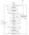
图4A图示了烟灰吹除统计过程控制程序的流程图;Figure 4A illustrates a flowchart of the statistical process control program for soot blowing;
图4B图示了多个热吸收数据分布曲线;Figure 4B illustrates a plurality of heat absorption data distribution curves;
图5图示了永久性成渣检测程序的流程图;和Figure 5 illustrates a flow chart of the permanent slagging detection procedure; and
图6图示了用于图示永久性成渣的多个热吸收分布曲线。Figure 6 illustrates a number of heat absorption profiles for illustrating permanent slagging.
具体实施方式Detailed ways
统计过程控制系统使用对于诸如烧燃料锅炉的热交换区段一致的烟灰吹除操作,采集该热交换区段的热吸收数据并且分析热吸收数据的分布以及热吸收分布的各种参数,以便重新调整所述烟灰吹除操作。该统计过程控制系统可以设置预期热吸收下限和预期热吸收上限,并且分别将它们与实际热吸收下限和实际热吸收上限进行比较,以确定是否要对烟灰吹除操作进行重新调整。A statistical process control system uses a consistent soot blowing operation for a heat exchange section such as a fuel fired boiler, collects heat absorption data for the heat exchange section and analyzes the distribution of the heat absorption data and various parameters of the heat absorption distribution in order to reconstruct Adjust the soot blowing operation. The statistical process control system can set a lower expected heat absorption limit and an upper expected heat absorption limit and compare them to an actual lower heat absorption limit and an upper actual heat absorption limit, respectively, to determine whether to readjust the soot blowing operation.
一般而言,此处描述的统计过程控制系统与基于基本原理的方法和基于经验模型的方法相比更可靠,并且易于实现为仅需要热吸收数据来实现的统计过程控制系统。而且,由于此处描述的统计过程控制系统使用热吸收数据,它与烟气温度的扰动和噪声无关,而且一般不会受到其影响,因此对于烟灰吹除器的操作和热交换区段的清洁度提供了更加统一的控制。In general, the statistical process control systems described here are more reliable than first principles-based and empirical model-based approaches, and are easy to implement as statistical process control systems that only require heat absorption data for implementation. Also, since the statistical process control system described here uses heat absorption data, which is independent of, and generally unaffected by, flue gas temperature disturbances and noise, it is critical for the operation of the soot blower and the cleaning of the heat exchange section Degrees provide more uniform control.
一般而言,统计过程控制系统的实现测量各个点处随时间变化的热吸收,以便确定在烟灰吹除操作之前和之后的热吸收差异,并且基于该热吸收统计来计算各种统计过程控制测量结果,以便确定烟灰吹除操作的有效性。该统计过程控制系统为锅炉或其他机器的热交换区段建立一致的烟灰吹除操作,并且降低控制烟灰吹除操作所必需的数据量。In general, implementations of statistical process control systems measure heat absorption over time at various points in order to determine the difference in heat absorption before and after a soot blowing operation, and based on this heat absorption statistics various statistical process control measures are calculated results in order to determine the effectiveness of the soot blowing operation. The statistical process control system establishes a consistent soot blowing operation for a heat exchange section of a boiler or other machine and reduces the amount of data necessary to control the soot blowing operation.
图1图示了典型锅炉100的锅炉蒸汽循环的方框图,该锅炉100可以用于例如火力发电厂。锅炉100可以包括各种区段,蒸汽或水可以以各种形式,例如过热蒸汽,再热蒸汽,等等流过这些区段。尽管图1所示的锅炉100具有水平设置的各种锅炉区段,但是在实际实施中,这些区段中的一个或多个可以垂直放置,尤其是因为加热各种锅炉区段,例如水冷壁吸收区段中蒸汽的烟气,是垂直上升的。FIG. 1 illustrates a block diagram of a boiler steam cycle of a
该锅炉100包括水冷壁吸收区段102,初级过热吸收区段104,过热吸收区段106和再热区段108。另外,锅炉100也可以包括一个或多个过热降温器110和112,以及节热器114。锅炉100所产生的主蒸汽用来驱动高压(HP)涡轮机116,而来自再热区段108的热的再热蒸汽用来驱动中压(IP)涡轮机118。通常,锅炉100还可以用来驱动低压(LP)涡轮机,在图1中未示出。The
主要负责产生蒸汽的水冷壁吸收区段102,包括许多管线,蒸汽通过这些管线进入鼓筒。进入水冷壁吸收区段102的给水可以被泵送通过节热器区段114。当在水冷壁吸收区段102中时,该给水吸收大量的热。该水冷壁区段102具有蒸汽鼓筒,该蒸汽鼓筒既包含水也包含蒸汽,而且该鼓筒中的水位也必须进行小心的控制。将在蒸汽鼓筒顶部采集的蒸汽馈送给初级过热吸收区段104,接下来馈送给过热吸收区段106,它们一起将蒸汽温度升高到非常高的水平。从过热吸收区段106输出的主蒸汽驱动高压涡轮机116来发电。The water
一旦主蒸汽驱动HP涡轮机116,则将蒸汽发送至再热吸收区段108,而从再热吸收区段108输出的热再热蒸汽用来驱动IP涡轮机118。过热降温器110和112可以用来控制要到达预期设置点的最终蒸汽温度。最终,可以将来自IP涡轮机118的蒸汽馈送通过LP涡轮机(此处未示出)到达蒸汽冷凝器(此处未示出),在那里将蒸汽冷凝为液态,并且从各种锅炉给水泵泵送用于下一循环给水,该循环再次重头开始。位于从锅炉排出的热的废气流中的节热器114使用该热气,以便在给水进入水冷壁吸收区段102之前,将额外的热传递给该给水。Once the main steam drives the
图2是锅炉区段200的示意图,该锅炉区段具有位于来自锅炉100的烟气路径中的热交换器202。锅炉区段200可以是上述各种热交换区段中任意一种的一部分,例如初级过热吸收区段104、再热吸收区段108,等等。本领域普通技术人员能够理解,尽管本例的锅炉区段200可以位于锅炉100的特定部分,但是该专利中图示的烟灰吹除器控制方法可以应用于该锅炉中可能发生热交换和烟灰堆积的任意区段。FIG. 2 is a schematic diagram of a boiler section 200 with a heat exchanger 202 located in the flue gas path from the
热交换器202包括用于运送蒸汽的许多管道204,这些蒸汽在混合器206中与喷淋水混合在一起。该热交换器202还将水和蒸汽的混合物转化为过热蒸汽。用箭头209示意性地表示输入至锅炉区段200的烟气,而用箭头211示意性地表示离开锅炉区段200的烟气。将锅炉区段200表示为包含六个烟灰吹除器208,210,212,214,216和218,用于除去热交换器202外表面上的烟灰。The heat exchanger 202 includes a plurality of pipes 204 for carrying steam which is mixed with the spray water in a mixer 206 . The heat exchanger 202 also converts the water and steam mixture into superheated steam. The flue gas input to the boiler section 200 is schematically indicated by arrow 209 and the flue gas exiting the boiler section 200 is schematically indicated by arrow 211 . Boiler section 200 is shown as including six soot blowers 208 , 210 , 212 , 214 , 216 and 218 for removing soot from the outer surfaces of heat exchanger 202 .
操作员可以通过计算机250来控制烟灰吹除器208,210,212,214,216和218的操作。可以将计算机250设计为在存储器252上存储一个或多个计算机程序,该存储器可以是随机存取存储器(RAM),只读存储器(ROM)等形式,其中这样的程序可以适于在计算机250的中央处理单元(CPU)254上进行处理。用户可以通过输入/输出控制器256与计算机250进行通信。计算机250各种部件中的每一个均可以通过内部总线258相互进行通信,该内部总线258也可以用来与外部总线260进行通信。计算机250可以使用外部通信总线260,与各个烟灰吹除器208,210,212,214,216和218中的每一个进行通信。An operator may control the operation of the soot blowers 208 , 210 , 212 , 214 , 216 and 218 through the computer 250 . Computer 250 may be designed to store one or more computer programs on memory 252, which may be in the form of random access memory (RAM), read-only memory (ROM), etc., where such programs may be Processing is performed on a central processing unit (CPU) 254 . A user may communicate with computer 250 through input/output controller 256 . Each of the various components of computer 250 can communicate with each other via internal bus 258 , which can also be used to communicate with external bus 260 . The computer 250 may communicate with each of the respective soot blowers 208 , 210 , 212 , 214 , 216 , and 218 using an external communication bus 260 .
烟灰吹除器208-218可以根据特定的烟灰吹除序列进行操作,该序列规定了要开启烟灰吹除器208-218中每一个的次序,烟灰吹除器208-218的操作频率,每个烟灰吹除器开启的时间长度,等等。尽管烧燃料锅炉的给定部分可以具有许多不同的热交换区段,但是可以用于烟灰吹除操作的蒸汽和水的供给是有限的。因此,每个热交换区段被分配给优先级,热交换区段中的烟灰吹除器根据此优先级进行操作。热交换区段中具有更高优先级的烟灰吹除器能够接收所需的水和蒸汽以充分地操作,而热交换区段中具有较低优先级的烟灰吹除器只能在能够获得所需水和蒸汽时进行操作。如以下将要进一步详细描述的,可以根据用于控制特定热交换区段的烟灰吹除器而执行的程序,来改变特定热交换区段的优先级。The soot blowers 208-218 may operate according to a particular soot blowing sequence, which specifies the order in which each of the soot blowers 208-218 is to be turned on, the frequency of operation of the soot blowers 208-218, the How long the soot blowers are on, etc. Although a given section of a fuel fired boiler may have many different heat exchange sections, the supply of steam and water available for soot blowing operations is limited. Therefore, each heat exchange section is assigned a priority according to which the soot blowers in the heat exchange section operate. Soot blowers with higher priority in the heat exchange section are able to receive the water and steam needed to operate adequately, while soot blowers with lower priority in the heat exchange section Operate when water and steam are required. As will be described in further detail below, the priority of a particular heat exchange section may be varied according to the program performed to control the soot blower of the particular heat exchange section.
图3图示了热吸收统计计算程序300的流程图,该程序可以用来计算锅炉100各个区段中任意一个,例如锅炉区段200的热吸收统计。热吸收统计计算程序300可以实现为软件、硬件、固件或者实现为其任意组合。当实现为软件时,热吸收统计计算程序300可以存储在只读存储器(ROM)、随机存取存储器(RAM)上,或者存储在用来执行烟灰吹除过程控制程序300的计算机所使用的任意其他存储设备上。热吸收统计计算程序300可以用来仅计算锅炉100的一个区段的热吸收统计,或者可选地,可以用来计算锅炉100中所有热交换区段的热吸收统计。FIG. 3 illustrates a flow chart of a heat absorption
框302通过建立操作的初始序列(当前操作排序),启动热吸收统计的计算。上述当前操作排序可以通过定义时间线的各个参数来描述,该时间线用于操作锅炉区段,例如锅炉区段200内的多个烟灰吹除器中的任何一个。例如,热吸收统计计算程序300的执行可以规定开启烟灰吹除器208的频率,保持烟灰吹除器208处于开启状态的时间长度,以及在两个连续的开启时间周期之间关闭烟灰吹除器208的时间长度。
框302还采集和存储与流过锅炉区段200的蒸汽有关的各种数据。例如,框302可以采集进入锅炉区段200的蒸汽的温度和压力,并且可以计算用Hi标示的锅炉区段200的进入焓(焓是流体的热能含量,它的单位是Btu/lb),从锅炉区段200排出的蒸汽温度和压力,用Ho标示的锅炉区段200的排出焓,用F(单位是lbs/Hr)标示的蒸汽流入锅炉区段200的流动速率,等等。Block 302 also collects and stores various data related to the steam flowing through boiler section 200 . For example, block 302 may collect the temperature and pressure of the steam entering boiler section 200, and may calculate the entry enthalpy of boiler section 200 denotedHi (enthalpy is the thermal energy content of a fluid, and its units are Btu/lb), The temperature and pressure of the steam exiting the boiler section 200, the exhaust enthalpy of the boiler section 200 denoted byH , the flow rate of steam into the boiler section 200 denoted by F (in lbs/Hr), and the like.
框304使用框302采集的数据,计算和存储锅炉区段200内的热吸收。在此例子中,用Q标示的锅炉区段200的热吸收可以给定为:
Q=F*(Ho-Hi)Q=F*(Ho -Hi )
作为选择,在某些热交换区段中,例如锅炉100的水冷壁吸收区段102的子区段中,可以利用热流传感器来直接测量热吸收Q。Alternatively, in certain heat exchange sections, such as subsections of the water
图3的框306评价框304采集和存储的热吸收数据量。例如,用户可以规定必须要由烟灰吹除过程控制程序采集的观测结果数目,在这种情况下框306将所采集的数据与用户提供的该规定进行比较。如果框306确定必需更多的数据,控制转回到框302。
当框306确定已经采集了充足数量的热吸收数据时,框308确定所采集的数据是否遵循正态分布。用户可以提供置信水平,热吸收统计计算程序300需要确定该热吸收数据是否以该置信水平正态分布。例如,用户可以规定热吸收数据必需以百分之九十五的置信水平正态分布,等等。如果框308确定热吸收数据未能以规定的置信水平正态分布,这可能是无规律的烟灰吹除排序的结果,则框309修改用于操作锅炉区段200内烟灰吹除器的当前操作排序,从而使操作排序更加一致。接着,控制转回到框302,采集更多的数据以获取热吸收数据的更多观测点。When block 306 determines that a sufficient amount of heat absorption data has been collected, block 308 determines whether the collected data follows a normal distribution. The user may provide a confidence level with which the heat absorption
如果框308确定该热吸收数据是正态分布,则框310计算用于锅炉区段200的多个热吸收统计数据。例如,框310可以计算热吸收均值,热吸收中值,热吸收方差,热吸收标准偏差,热吸收偏度,等等。If
此后,框312评价框310计算的热吸收统计数据。特别地,框312可以评价相对于热吸收统计计算程序300的用户提供的许多测量的热吸收统计数据,或者相对于许多工业平均数的热吸收统计数据,等等。Thereafter, block 312 evaluates the heat absorption statistics calculated by
在热吸收统计计算程序300的实现中,框312可以配备有目标控制下限和目标控制上限,锅炉区段的实际热吸收相对于该上下限来进行评价。替代地,热吸收统计计算程序300可以使用框310计算的长期热吸收统计数据,来计算该目标控制下限和目标控制上限。例如,热吸收统计计算程序300的执行可以使用热吸收均值和热吸收标准偏差,来确定该目标控制下限和目标控制上限。In an implementation of the heat absorption
在框312评价了热吸收统计量之后,框314确定是否必需要改变烟灰吹除器的当前操作排序。例如,框314可以确定必需要改变开启烟灰吹除器的频率,保持烟灰吹除器处于开启状态的时间长度,以及在两个连续的开启周期之间关闭烟灰吹除器的时间长度等中的至少一个。在热吸收统计计算程序300的一种实现中,框314可以确定如果实际热吸收均值低于目标控制下限,则必需要改变当前操作排序的一个或多个操作参数。After evaluating the heat absorption statistics at
如果框314确定必需要改变烟灰吹除器的当前操作排序,则框316计算要应用于当前操作排序各个参数中任意一个的变化。框316可以使用框310计算的各种热吸收统计,来确定要应用于当前操作排序各个参数的变化。例如,在热吸收统计计算程序300的实现中,框314可以确定要应用于烟灰吹除器要保持开启状态的时间长度的变化,应该是实际热吸收均值和目标控制下限之间差值的函数。然而,框314还可以确定该烟灰吹除是高效运转的,并且不必改变烟灰吹除器的当前操作排序,在这种情况下控制可以转到框302,以便继续监控该烟灰吹除过程而没有任何变化。If
需要注意的是,尽管热吸收统计计算程序300在图2中进行了图解说明,并且关于锅炉区段200在以上进行了描述,但是热吸收统计计算程序300还可以应用于锅炉100的任意其他热交换区段。而且,尽管在热吸收统计计算程序300中将框312-316执行的功能图示为由三个不同的框来执行,但在替代实现中,这些功能也可以由单一框或者由单独程序来执行。It should be noted that although the heat absorption
图4A图示了统计过程控制程序350的实现的流程图,该程序可以执行框312-316的功能。框352可以确定特定热交换区段的热吸收值的预期分布特性。这些特性的确定可以包括选择目标控制下限QLCL,目标控制上限QUCL,以及该特定热交换区段的预期分布的其他特性。随后,框354可以使用下述公式来计算热吸收均值Qmean:FIG. 4A illustrates a flowchart of an implementation of a statistical
其中N表示给定采样中所包含的热吸收观测结果的数目,而Qi是第i个观测结果的热吸收值。框356可以使用下述公式计算热吸收标准偏差Qσ:where N denotes the number of heat absorption observations included in a given sample, and Qi is the heat absorption value of the ith observation.
随后,框358可以在描绘各热吸收值分布的曲线上确定实际下限Qm-3σ和实际上限Qm+3σ。尽管在统计过程控制程序350的本实现中,实际下限Qm-3σ和实际上限Qm+3σ仅仅是热吸收均值Qmean和热吸收标准偏差Qσ的函数,但在替代实现中,诸如方差的替代统计值可以用来计算替代实际下限和替代实际上限。而且,尽管在本例中,将实际下限Qm-3σ和实际上限Qm+3σ确定为距离热吸收均值Qmean有3西格马点(3σ),但在实际中,也可以使用位于距离热吸收均值Qmean有x西格马点(其中x是统计过程控制程序350的用户可以选择的数字)的替代实际下限Qm-xσ和替代实际上限Qm+xσ。如果需要的话,x可以是整数或者可以是任意实数。
随后,框360将实际下限Qm-3σ与目标控制下限QLCL进行比较,并将实际上限Qm+3σ与目标控制上限QUCL进行比较。框360可以配备有一系列的规则,这些规则可以用来基于该比较结果执行该比较,框360可以生成关于需要对当前操作排序的一个或多个参数进行改变的决定。Then, block 360 compares the actual lower limit Qm-3σ to the target lower control limit QLCL and compares the actual upper limit Qm+3σ to the target upper control limit QUCL .
对特定热交换区段的实际下限Qm-3σ和实际上限Qm+3σ的评价,提供关于该特定热交换区段的热吸收值实际分布的信息。通过比较实际下限Qm-3σ与目标控制下限QLCL,以及比较实际上限Qm+3σ与目标控制上限QUCL,统计过程控制程序350的框360确定在一段特定时期测量的,热吸收值的实际分布是否近似地等于热吸收值的预期分布。The evaluation of the practical lower limit Qm-3σ and the practical upper limit Qm+3σ of a particular heat exchange section provides information on the actual distribution of heat absorption values for that particular heat exchange section. By comparing the actual lower limit Qm-3σ to the target lower control limit QLCL , and comparing the actual upper limit Qm+3σ to the target upper control limit QUCL , block 360 of the statistical
如果框360确定实际下限Qm-3σ近似地等于目标控制下限QLCL,并且比较实际上限Qm+3σ近似等于目标控制上限QUCL,则热吸收值的实际分布近似地等于热吸收值的预期分布。在这种情况下,框360可以决定用来操作烟灰吹除器的当前操作排序正在适当地发挥作用,或者成功地实现了对烟灰吹除操作的预期控制。因此,无须对当前操作排序的任何操作参数进行任何变化,并且如图4A的路径A所示,控制转回到框354。If
在某些情形下,框360可以确定目标控制下限QLCL大于实际下限Qm-3σ(QLCL>Qm-3σ),并且目标控制上限QUCL也大于实际上限Qm+3σ(QUCL>Qm+3σ)。如图4B中的分布380所示,该结果(图4A中的路径B)表示热吸收观测结果的实际分布位于预期分布的左侧。在这种情形下,框362(它可以用图3的框316来执行)可以减少当前操作排序中连续烟灰吹除操作之间的空闲时间,或者提高热交换区段的烟灰吹除优先级,以便将热吸收观测结果的实际分布向右平移。较低的空闲时间或较高的吹除优先级能够导致更频繁的烟灰吹除操作,并因此除去更高数量的烟灰沉积物,这将会导致将热吸收数据的分布缩窄到由目标控制下限QLCL和目标控制上限QUCL规定的预期水平。空闲时间和吹除优先级的改变量可以由锅炉100的用户根据经验来确定。In some cases, block 360 may determine that the target lower control limit QLCL is greater than the actual lower limit Qm-3σ (QLCL >Qm-3σ ), and the target upper control limit QUCL is also greater than the actual upper limit Qm+3σ (QUCL > Qm+3σ ). As shown by
在另一情形下,框360可以确定目标控制下限QLCL低于实际下限Qm-3σ(QLCL<Qm-3σ),并且目标控制上限QUCL也低于实际上限Qm+3σ(QUCL<Qm+3σ)。如图4B中的分布382所示,该结果(图4A中的路径C)表示热吸收观测结果的实际分布位于预期分布的右侧。通常,该情形可以表示过多的烟灰吹除。在这种情形下,框364可以增加当前操作排序中连续烟灰吹除操作之间的空闲时间,或者降低热交换区段的烟灰吹除优先级,以便将热吸收观测结果的实际分布向左平移。较高的空闲时间或较低的吹除优先级能够导致更低频率的烟灰吹除操作,并因此除去更少数量的烟灰沉积物,这将会导致将热吸收数据的分布展宽到由目标控制下限QLCL和目标控制上限QUCL规定的预期水平。空闲时间和吹除优先级的改变量可以由锅炉100的用户根据经验来确定。In another case, block 360 may determine that the target lower control limit QLCL is lower than the actual lower limit Qm-3σ (QLCL < Qm-3σ ), and the target upper control limit QUCL is also lower than the actual upper limit Qm+3σ (QUCL <Qm+3σ ). As shown by
作为选择,框360可以确定目标控制下限QLCL高于实际下限Qm-3σ(QLCL>Qm-3σ),而目标控制上限QUCL低于实际上限Qm+3σ(QUCL<Qm+3σ)。如图4B中的分布384所示,该结果(图4A中的路径D)表示热吸收观测结果的实际分布比预期分布宽。在这种情形下,框366将当前的实际热吸收Qactual与热吸收均值Qmean进行比较。如果框366确定Qactual<Qmean,则框368减少连续烟灰吹除操作之间的空闲时间,或者提高热交换区段的烟灰吹除优先级。较低的空闲时间或较高的吹除优先级能够导致更频繁的烟灰吹除操作,并因此除去更高数量的烟灰沉积物,这将会导致将实际控制下限Qm-3σ朝向预期控制下限QLCL平移。空闲时间和吹除优先级的改变量可以由锅炉100的用户根据经验来确定。Alternatively, block 360 may determine that the target lower control limit QLCL is higher than the actual lower limit Qm-3σ (QLCL >Qm-3σ ), while the target upper control limit QUCL is lower than the actual upper limit Qm+3σ (QUCL <Qm +3σ ). As shown by
另一方面,如果框366确定Qactual>Qmean,则框370增加连续烟灰吹除操作之间的空闲时间,或者降低热交换区段的烟灰吹除优先级。较高的空闲时间或较低的吹除优先级能够导致较低频率的烟灰吹除操作,并因此除去更少数量的烟灰沉积物,这将会导致将实际控制上限Qm+3σ朝向预期控制上限QUCL平移。空闲时间和吹除优先级的改变量可以由锅炉100的用户根据经验来确定。On the other hand, if
更进一步,框360可以确定目标控制下限QLCL低于实际下限Qm-3σ(QLCL<Qm-3σ),而目标控制上限QUCL大于实际上限Qm+3σ(QUCL>Qm+3σ)。如图4B中的分布386所示,该结果(图4A中的路径E)表示热吸收观测结果的实际分布比预期分布窄。在这种情形下,框372将当前的实际热吸收Qactual与热吸收均值Qmean进行比较。如果框372确定Qactual<Qmean,则框374增加连续烟灰吹除操作之间的空闲时间,或者降低热交换区段的烟灰吹除优先级。较高的空闲时间或较低的吹除优先级能够导致较低频率的烟灰吹除操作,并因此除去更少数量的烟灰沉积物,这将会导致将实际控制上限Qm+3σ朝向预期控制上限QUCL平移。空闲时间和吹除优先级的改变量可以由锅炉100的用户根据经验来确定。Furthermore, block 360 may determine that the target lower control limit QLCL is lower than the actual lower limit Qm-3σ (QLCL <Qm-3σ ), while the target upper control limit QUCL is greater than the actual upper limit Qm+3σ (QUCL >Qm+ 3σ ). As shown by
另一方面,如果框372确定Qactual>Qmean,则框376减少连续烟灰吹除操作之间的空闲时间,或者提高热交换区段的烟灰吹除优先级。较低的空闲时间或较高的吹除优先级能够导致更频繁的烟灰吹除操作,并因此除去更高数量的烟灰沉积物,这将会导致将实际控制下限Qm-3σ朝向预期控制下限QLCL平移。空闲时间和吹除优先级的改变量可以由锅炉100的用户根据经验来确定。On the other hand, if
随后,框378评价框354-376所采取的过程的有效性,以便确定目标控制上限QUCL和目标控制下限QLCL的当前选择在控制特定热交换区段的烟灰吹除操作中是否是有效的。框378可以采集与分布曲线380-386在框354-376的操作的某些循环上的平移有关的各种统计数据。如果框378确定在这几个循环的末端,分布曲线380-386已经显著地平移到新的位置,例如用(图4B的)分布曲线384表示的位置,则框378可以决定框354-376所采取的过程在避免热交换区段的成渣中是无效的,因此将控制转回到框352,并请求统计过程控制程序350的用户选择目标控制上限QUCL和目标控制下限QLCL的新数值。Subsequently, block 378 evaluates the effectiveness of the process undertaken by blocks 354-376 to determine whether the current selection of target upper control limit QUCL and target lower control limit QLCL is effective in controlling the soot blowing operation of the particular heat exchange section .
如曲线380所示的热吸收值的宽分布可以表示尽管热交换区段的平均传热效率并未随时间发生变化,但是传热效率的各个观测结果更可能与平均传热效率不同。另一方面,如曲线382所示的热吸收值的窄分布可以表示尽管热交换区段的平均传热效率并未随时间发生变化,但是传热效率的各个观测结果更少可能与平均传热效率不同。The broad distribution of heat absorption values as shown by
如分布曲线384所示的热吸收值分布的向左平移可以表示由于热交换区段中更高数量的烟灰沉积物(成渣),热交换区段的传热效率的总体降低。另一方面,如分布曲线386所示的热吸收值分布的向右平移可以表示热交换区段的传热效率的总体提高。该提高的效率可能是比必需更高的烟灰吹除率的结果,并且可能会损坏热交换区段中的各种水和蒸汽输送管。A leftward shift in the distribution of heat absorption values as shown by
尽管图4A-4B图示了统计过程控制程序350的一种实现,图5图示了另一种统计过程控制程序,该程序可以用来确定锅炉100的热交换区段内的永久性成渣。具体地说,图5图示了成渣检测程序400,该程序评价由于烟灰吹除而产生的热吸收变化的分布数据,以及热吸收变化均值ΔQmean和特定热交换区段中烟灰吹除频率之间的相关性,以便确定特定热交换区段中的任何永久性成渣。While FIGS. 4A-4B illustrate one implementation of the statistical
该情形用图6的一系列分布曲线450-454进行进一步的图解说明,其中曲线450-454中的每一条均表示特定热交换区段在特定时期内的热吸收变化值ΔQ的分布,其中ΔQ可以定义为:This situation is further illustrated by the series of distribution curves 450-454 of FIG. 6, wherein each of the curves 450-454 represents the distribution of the heat absorption change value ΔQ of a specific heat exchange section over a specific period of time, where ΔQ can be defined as:
ΔQ=Q烟灰吹除后-Q烟灰吹除前ΔQ = Qafter soot blowing - Qbefore soot blowing
例如,曲线450可以表示特定热交换区段的热吸收变化值的预期分布。如图6所示,在理想情况下,热吸收变化均值ΔQmean可以具有近似100的值。然而,由于永久性成渣(即烟灰吹除不再有效),曲线450可以平移到由曲线452表示的位置,其中实际吸收变化均值ΔQmean可以变为近似等于只有80或更少。该成渣检测程序400可以用来确定热交换区段中的这种成渣。For example, curve 450 may represent an expected distribution of heat absorption change values for a particular heat exchange segment. As shown in FIG. 6 , the heat absorption variation mean ΔQmean may have a value of approximately 100 in an ideal case. However, due to permanent slagging (ie, soot blowing is no longer effective), curve 450 may shift to a position represented by curve 452 where the actual absorption change mean ΔQmean may become approximately equal to only 80 or less. The slagging
成渣检测程序400的框402-409的操作类似于热吸收统计计算程序300的框302-309的操作,除了框302-309计算关于特定热交换区段的热吸收Q的各种统计,而框402-409计算关于特定热交换区段的热吸收变化ΔQ的各种统计。随后,框410将热吸收数据分为不同时间上的部分。例如,如果成渣检测程序400具有与之相关联的热吸收数据,例如一个月的热交换区段的操作,则框410可以在时间上将该热吸收数据分为几组不同的数据。可选地,框410可以在滚动基础上存储最后的确定周期数目的数据,从而仅对最后一个月的数据进行分析,并丢弃来自先前周期的所有数据。The operation of blocks 402-409 of the slagging
框412计算由框410提供的不同组数据的均值。例如,框412可以计算先前月每一天的吸收变化值均值。随后,框414分析这些值以便确定在该数据中是否存在一种倾向。具体地说,框414确定该均值是否显示了时间上的任何渐降或渐升。均值的渐降可以表示热交换区段正在朝向永久性成渣的趋势,并且在当前烟灰吹除实践中进行变化是必需的。如果检测到吸收变化均值中的位移,则可以执行相关性分析。
框418计算用Corrm,f表示的,特定热交换区段的热吸收变化均值ΔQmean和该特定热交换区段中烟灰吹除频率之间的相关性。框420可以确定相关值Corrm,f是否高于在特定置信水平上的给定阈值。如果相关值Corrm,f高于给定阈值,这表示热吸收变化均值ΔQmean的向左平移显著地与烟灰吹除频率相关,则框420可以将控制传回给框402,以便继续其正常模式的成渣检测程序400的操作。然而,如果框418确定该相关值并不高于给定阈值,则框420就通知用户,在所评价的热交换区段中可能存在永久性成渣的情况。需要注意的是,尽管成渣检测程序400的上述实现使用热吸收变化均值ΔQmean和烟灰吹除频率之间的相关性,但在替代实施例中,同样也可以使用热吸收变化均值ΔQmean,和在每一序列期间将烟灰吹除器保持在开启状态的时间长度之间,或者和当前操作排序的某些其他参数之间的相关性。
尽管前述文本阐述了本发明众多不同实施例的详细描述,但是应当理解本发明的范围由本专利最后提出的权利要求的文字来限定。该详细描述应当理解为仅仅是示例性的,而非描述了本发明所有可能的实施例,因为描述所有可能的实施例即使不是不可能的话,也是不切实际的。利用当前技术或者在本专利提交日期之后发展的技术,可以实现众多的替代实施例,这些实施例仍将落在限定本发明的权利要求的范围之内。While the foregoing text sets forth a detailed description of numerous different embodiments of the invention, it should be understood that the scope of the invention is defined by the words of the claims at the end of this patent. The detailed description is to be understood as exemplary only and does not describe all possible embodiments of the invention, since describing all possible embodiments would be impractical, if not impossible. Numerous alternative embodiments could be implemented, using either current technology or technology developed after the filing date of this patent, which would still fall within the scope of the claims defining the invention.
因此,在不脱离本发明精神和范围的前提下,可以对此处描述和说明的技术和结构进行多种改进和变化。因此,应当理解此处描述的方法和装置仅仅是示例性的,而非限制本发明的范围。Accordingly, various modifications and changes may be made in the techniques and structures described and illustrated herein without departing from the spirit and scope of the invention. Therefore, it should be understood that the methods and devices described herein are illustrative only and do not limit the scope of the present invention.
Claims (23)
Translated fromChinesePriority Applications (1)
| Application Number | Priority Date | Filing Date | Title |
|---|---|---|---|
| CN201310021448.7ACN103075739B (en) | 2005-06-06 | 2006-06-06 | Utilize statistical Process Control to control the method and apparatus of soot blowing |
Applications Claiming Priority (2)
| Application Number | Priority Date | Filing Date | Title |
|---|---|---|---|
| US11/146,170US7383790B2 (en) | 2005-06-06 | 2005-06-06 | Method and apparatus for controlling soot blowing using statistical process control |
| US11/146,170 | 2005-06-06 |
Related Child Applications (1)
| Application Number | Title | Priority Date | Filing Date |
|---|---|---|---|
| CN201310021448.7ADivisionCN103075739B (en) | 2005-06-06 | 2006-06-06 | Utilize statistical Process Control to control the method and apparatus of soot blowing |
Publications (2)
| Publication Number | Publication Date |
|---|---|
| CN1877198A CN1877198A (en) | 2006-12-13 |
| CN1877198Btrue CN1877198B (en) | 2013-03-06 |
Family
ID=36694872
Family Applications (2)
| Application Number | Title | Priority Date | Filing Date |
|---|---|---|---|
| CN2006100833896AActiveCN1877198B (en) | 2005-06-06 | 2006-06-06 | Method and apparatus for controlling soot blowing using statistical process control |
| CN201310021448.7AActiveCN103075739B (en) | 2005-06-06 | 2006-06-06 | Utilize statistical Process Control to control the method and apparatus of soot blowing |
Family Applications After (1)
| Application Number | Title | Priority Date | Filing Date |
|---|---|---|---|
| CN201310021448.7AActiveCN103075739B (en) | 2005-06-06 | 2006-06-06 | Utilize statistical Process Control to control the method and apparatus of soot blowing |
Country Status (5)
| Country | Link |
|---|---|
| US (2) | US7383790B2 (en) |
| CN (2) | CN1877198B (en) |
| CA (1) | CA2548211C (en) |
| DE (1) | DE102006026246B4 (en) |
| GB (2) | GB2428312B (en) |
Cited By (1)
| Publication number | Priority date | Publication date | Assignee | Title |
|---|---|---|---|---|
| TWI705316B (en)* | 2018-04-27 | 2020-09-21 | 日商三菱日立電力系統股份有限公司 | Boiler operation support device, boiler operation support method, and boiler learning model creation method |
Families Citing this family (28)
| Publication number | Priority date | Publication date | Assignee | Title |
|---|---|---|---|---|
| US7383790B2 (en) | 2005-06-06 | 2008-06-10 | Emerson Process Management Power & Water Solutions, Inc. | Method and apparatus for controlling soot blowing using statistical process control |
| US7827006B2 (en)* | 2007-01-31 | 2010-11-02 | Fisher-Rosemount Systems, Inc. | Heat exchanger fouling detection |
| CA2680706C (en)* | 2007-03-12 | 2018-01-09 | Emerson Process Management Power & Water Solutions, Inc. | Use of statistical analysis in power plant performance monitoring |
| US7890197B2 (en)* | 2007-08-31 | 2011-02-15 | Emerson Process Management Power & Water Solutions, Inc. | Dual model approach for boiler section cleanliness calculation |
| US8381690B2 (en) | 2007-12-17 | 2013-02-26 | International Paper Company | Controlling cooling flow in a sootblower based on lance tube temperature |
| JP5417068B2 (en)* | 2009-07-14 | 2014-02-12 | 株式会社日立製作所 | Oxyfuel boiler and control method for oxygen fired boiler |
| US20110203535A1 (en)* | 2010-02-19 | 2011-08-25 | Nrg Energy, Inc. | Method and System for Sootblower Flow Analyzer |
| US9335042B2 (en) | 2010-08-16 | 2016-05-10 | Emerson Process Management Power & Water Solutions, Inc. | Steam temperature control using dynamic matrix control |
| US9447963B2 (en) | 2010-08-16 | 2016-09-20 | Emerson Process Management Power & Water Solutions, Inc. | Dynamic tuning of dynamic matrix control of steam temperature |
| US9217565B2 (en)* | 2010-08-16 | 2015-12-22 | Emerson Process Management Power & Water Solutions, Inc. | Dynamic matrix control of steam temperature with prevention of saturated steam entry into superheater |
| US9163828B2 (en) | 2011-10-31 | 2015-10-20 | Emerson Process Management Power & Water Solutions, Inc. | Model-based load demand control |
| US8892477B2 (en) | 2011-12-09 | 2014-11-18 | Brad Radl | Method and system for fuzzy constrained sootblowing optimization |
| CN103047666B (en)* | 2012-12-20 | 2016-06-01 | 浙江省电力公司电力科学研究院 | A kind of boiler convection heating surface blows method and the device of ash |
| MX368425B (en)* | 2013-10-18 | 2019-10-02 | Fuel Tech Inc | A process for controlling injection of magnesium oxide for controlling so3 with enhanced boiler efficiency. |
| CN103744294B (en)* | 2014-01-28 | 2015-12-30 | 烟台龙源电力技术股份有限公司 | Based on the multiple goal soot blowing and optimal method of fuzzy control, server and system |
| CN103759277B (en)* | 2014-01-28 | 2015-12-02 | 烟台龙源电力技术股份有限公司 | Coal-fired power station boiler intelligent ash blowing closed loop control method, device and system |
| US9541282B2 (en) | 2014-03-10 | 2017-01-10 | International Paper Company | Boiler system controlling fuel to a furnace based on temperature of a structure in a superheater section |
| BR112017001511B1 (en) | 2014-07-25 | 2021-03-02 | International Paper Company | methods, system and computer program product to detect fouling of a boiler heat exchanger |
| CN104197776B (en)* | 2014-08-19 | 2016-08-17 | 广州飞机维修工程有限公司 | A kind of explosion-proof cleaning equipment of civil aircraft fuel oil and lubricating oil heat exchanger |
| CN105676634B (en)* | 2014-11-17 | 2019-12-10 | 通用电气公司 | Optimized systems and methods for reducing slag formation |
| US11428482B2 (en)* | 2016-04-12 | 2022-08-30 | Angara Global Ltd. | Industrial cleaning systems, including solutions for removing various types of deposits, and cognitive cleaning |
| US10033317B2 (en)* | 2016-10-14 | 2018-07-24 | Florida Power & Light Company | Automated maximum sustained rate system and method |
| CN109426148B (en)* | 2017-08-25 | 2021-10-19 | 中核兰州铀浓缩有限公司 | Method for realizing automatic adjustment of cycle period time in ash removal process of coal-fired boiler |
| JP2017203621A (en)* | 2017-08-28 | 2017-11-16 | 三菱日立パワーシステムズ株式会社 | Method for monitoring and operating carbon-containing fuel heat exchanger |
| US20210341140A1 (en) | 2020-05-01 | 2021-11-04 | International Paper Company | System and methods for controlling operation of a recovery boiler to reduce fouling |
| JP6761558B1 (en)* | 2020-06-03 | 2020-09-23 | 三菱重工環境・化学エンジニアリング株式会社 | Boiler tube group adhering ash removal system |
| CN114034054A (en)* | 2021-10-30 | 2022-02-11 | 山东上奥电力科技有限公司 | System and method for operation optimization and condition monitoring of sootblowers in utility boilers |
| CN118729304B (en)* | 2024-09-02 | 2024-11-29 | 长沙天宁热电有限公司 | Air shock wave soot blowing control system and control method |
Citations (8)
| Publication number | Priority date | Publication date | Assignee | Title |
|---|---|---|---|---|
| US3137278A (en)* | 1961-01-10 | 1964-06-16 | Diamond Power Speciality | Blower type cleaning for heat exchanging apparatus |
| US4085438A (en)* | 1976-11-11 | 1978-04-18 | Copes-Vulcan Inc. | Digital sootblower control systems and methods therefor |
| JPS62294804A (en) | 1987-04-24 | 1987-12-22 | Babcock Hitachi Kk | Control of soot blower |
| US4996951A (en)* | 1990-02-07 | 1991-03-05 | Westinghouse Electric Corp. | Method for soot blowing automation/optimization in boiler operation |
| US5181482A (en)* | 1991-12-13 | 1993-01-26 | Stone & Webster Engineering Corp. | Sootblowing advisor and automation system |
| US5764535A (en)* | 1995-11-07 | 1998-06-09 | Hitachi, Ltd. | Furnace inside state estimation control apparatus of pulverized coal combustion furnace |
| US6325025B1 (en)* | 1999-11-09 | 2001-12-04 | Applied Synergistics, Inc. | Sootblowing optimization system |
| US6736089B1 (en)* | 2003-06-05 | 2004-05-18 | Neuco, Inc. | Method and system for sootblowing optimization |
Family Cites Families (20)
| Publication number | Priority date | Publication date | Assignee | Title |
|---|---|---|---|---|
| CH357742A (en) | 1958-03-12 | 1961-10-31 | Sulzer Ag | Method and device for influencing the initial state of the steam at at least two intermediate superheaters of a steam generator system assigned to different expansion stages |
| CH358096A (en) | 1958-03-12 | 1961-11-15 | Sulzer Ag | Process for regulating the output temperatures at superheaters in a steam generator system and equipment for carrying out the process |
| DE3009565A1 (en)* | 1980-03-13 | 1981-09-24 | Babcock-BSH AG vormals Büttner-Schilde-Haas AG, 4150 Krefeld | DRYING SYSTEM |
| JPS6026213A (en)* | 1983-07-22 | 1985-02-09 | Mitsubishi Heavy Ind Ltd | Optimum control system of soot blower |
| US4718376A (en) | 1985-11-01 | 1988-01-12 | Weyerhaeuser Company | Boiler sootblowing control system |
| US5027751A (en) | 1990-07-02 | 1991-07-02 | Westinghouse Electric Corp. | Method and apparatus for optimized boiler operation |
| GB9220856D0 (en)* | 1992-10-03 | 1992-11-18 | Boiler Management Systems Limi | Improvements in or relating to boiler wall cleaning |
| US5440478A (en) | 1994-02-22 | 1995-08-08 | Mercer Forge Company | Process control method for improving manufacturing operations |
| JP3614751B2 (en) | 2000-03-21 | 2005-01-26 | 東京電力株式会社 | Thermal efficiency diagnosis method and apparatus for combined power plant |
| FI117143B (en)* | 2000-11-30 | 2006-06-30 | Metso Automation Oy | Sweetening method and apparatus of a soda boiler |
| FI20011742L (en) | 2001-08-31 | 2003-03-01 | Metso Field Systems Oy | Method and system for analyzing the performance of an industrial process control loop |
| DE10151250A1 (en) | 2001-10-17 | 2003-05-08 | Bayer Ag | Process for determining a complex correlation pattern from process and plant data |
| JP2003172582A (en)* | 2001-12-03 | 2003-06-20 | Ishikawajima Harima Heavy Ind Co Ltd | drying furnace |
| US6928937B2 (en)* | 2002-12-26 | 2005-08-16 | Diamond Power International, Inc. | Sootblowing control based on boiler thermal efficiency optimization |
| US20050033464A1 (en) | 2003-08-06 | 2005-02-10 | Siemens Dematic Electronics Assembly Systems, Inc. | Real time closed-loop process control system for defect prevention |
| US7109446B1 (en) | 2005-02-14 | 2006-09-19 | Emerson Process Management Power & Water Solutions, Inc. | Method and apparatus for improving steam temperature control |
| US8140296B2 (en) | 2005-06-06 | 2012-03-20 | Emerson Process Management Power & Water Solutions, Inc. | Method and apparatus for generalized performance evaluation of equipment using achievable performance derived from statistics and real-time data |
| US7383790B2 (en) | 2005-06-06 | 2008-06-10 | Emerson Process Management Power & Water Solutions, Inc. | Method and apparatus for controlling soot blowing using statistical process control |
| JP4695935B2 (en) | 2005-07-12 | 2011-06-08 | ルネサスエレクトロニクス株式会社 | Anomaly detection system and anomaly detection method |
| CA2680706C (en) | 2007-03-12 | 2018-01-09 | Emerson Process Management Power & Water Solutions, Inc. | Use of statistical analysis in power plant performance monitoring |
- 2005
- 2005-06-06USUS11/146,170patent/US7383790B2/enactiveActive
- 2006
- 2006-05-25CACA2548211Apatent/CA2548211C/enactiveActive
- 2006-06-05GBGB0610955Apatent/GB2428312B/enactiveActive
- 2006-06-05GBGB0916807Apatent/GB2462214B/enactiveActive
- 2006-06-06CNCN2006100833896Apatent/CN1877198B/enactiveActive
- 2006-06-06DEDE102006026246.8Apatent/DE102006026246B4/enactiveActive
- 2006-06-06CNCN201310021448.7Apatent/CN103075739B/enactiveActive
- 2007
- 2007-07-27USUS11/829,546patent/US7890214B2/enactiveActive
Patent Citations (8)
| Publication number | Priority date | Publication date | Assignee | Title |
|---|---|---|---|---|
| US3137278A (en)* | 1961-01-10 | 1964-06-16 | Diamond Power Speciality | Blower type cleaning for heat exchanging apparatus |
| US4085438A (en)* | 1976-11-11 | 1978-04-18 | Copes-Vulcan Inc. | Digital sootblower control systems and methods therefor |
| JPS62294804A (en) | 1987-04-24 | 1987-12-22 | Babcock Hitachi Kk | Control of soot blower |
| US4996951A (en)* | 1990-02-07 | 1991-03-05 | Westinghouse Electric Corp. | Method for soot blowing automation/optimization in boiler operation |
| US5181482A (en)* | 1991-12-13 | 1993-01-26 | Stone & Webster Engineering Corp. | Sootblowing advisor and automation system |
| US5764535A (en)* | 1995-11-07 | 1998-06-09 | Hitachi, Ltd. | Furnace inside state estimation control apparatus of pulverized coal combustion furnace |
| US6325025B1 (en)* | 1999-11-09 | 2001-12-04 | Applied Synergistics, Inc. | Sootblowing optimization system |
| US6736089B1 (en)* | 2003-06-05 | 2004-05-18 | Neuco, Inc. | Method and system for sootblowing optimization |
Cited By (1)
| Publication number | Priority date | Publication date | Assignee | Title |
|---|---|---|---|---|
| TWI705316B (en)* | 2018-04-27 | 2020-09-21 | 日商三菱日立電力系統股份有限公司 | Boiler operation support device, boiler operation support method, and boiler learning model creation method |
Also Published As
| Publication number | Publication date |
|---|---|
| HK1136650A1 (en) | 2010-07-02 |
| GB0916807D0 (en) | 2009-11-04 |
| GB2428312A (en) | 2007-01-24 |
| US20060283406A1 (en) | 2006-12-21 |
| US7890214B2 (en) | 2011-02-15 |
| CN103075739A (en) | 2013-05-01 |
| GB0610955D0 (en) | 2006-07-12 |
| US20080016647A1 (en) | 2008-01-24 |
| GB2428312B (en) | 2009-12-30 |
| DE102006026246A1 (en) | 2006-12-07 |
| CA2548211C (en) | 2015-12-01 |
| CN1877198A (en) | 2006-12-13 |
| GB2462214B (en) | 2010-05-26 |
| GB2462214A (en) | 2010-02-03 |
| CN103075739B (en) | 2015-12-23 |
| US7383790B2 (en) | 2008-06-10 |
| DE102006026246B4 (en) | 2019-02-14 |
| CA2548211A1 (en) | 2006-12-06 |
Similar Documents
| Publication | Publication Date | Title |
|---|---|---|
| CN1877198B (en) | Method and apparatus for controlling soot blowing using statistical process control | |
| US7890197B2 (en) | Dual model approach for boiler section cleanliness calculation | |
| EP2444869B1 (en) | Method and apparatus for generalized performance evaluation of equipment using achievable performance derived from statistics and real-time data | |
| US8140296B2 (en) | Method and apparatus for generalized performance evaluation of equipment using achievable performance derived from statistics and real-time data | |
| JPH0211811B2 (en) | ||
| US20100212609A1 (en) | Systems and methods for controlling the operation of sootblowers | |
| CN103047666B (en) | A kind of boiler convection heating surface blows method and the device of ash | |
| AU2021387203B2 (en) | Abnormality detection device and abnormality detection method | |
| JP7710348B2 (en) | System and method for removing deposits | |
| Sarunac et al. | Sootblowing operation: the last optimization frontier | |
| JP2004124852A (en) | Evaluation method and evaluation device for exhaust heat recovery equipment |
Legal Events
| Date | Code | Title | Description |
|---|---|---|---|
| C06 | Publication | ||
| PB01 | Publication | ||
| C10 | Entry into substantive examination | ||
| SE01 | Entry into force of request for substantive examination | ||
| C14 | Grant of patent or utility model | ||
| GR01 | Patent grant |