CN1872468B - Miter Lock Assembly for Miter Saws - Google Patents
Miter Lock Assembly for Miter SawsDownload PDFInfo
- Publication number
- CN1872468B CN1872468BCN2006100998511ACN200610099851ACN1872468BCN 1872468 BCN1872468 BCN 1872468BCN 2006100998511 ACN2006100998511 ACN 2006100998511ACN 200610099851 ACN200610099851 ACN 200610099851ACN 1872468 BCN1872468 BCN 1872468B
- Authority
- CN
- China
- Prior art keywords
- saw
- workbench
- handle
- bracing frame
- mitre saw
- Prior art date
- Legal status (The legal status is an assumption and is not a legal conclusion. Google has not performed a legal analysis and makes no representation as to the accuracy of the status listed.)
- Expired - Fee Related
Links
- 238000007792additionMethods0.000description2
- 230000000712assemblyEffects0.000description2
- 238000000429assemblyMethods0.000description2
- 238000006467substitution reactionMethods0.000description2
- 229910001369BrassInorganic materials0.000description1
- 229910000639Spring steelInorganic materials0.000description1
- 229910052782aluminiumInorganic materials0.000description1
- XAGFODPZIPBFFR-UHFFFAOYSA-NaluminiumChemical compound[Al]XAGFODPZIPBFFR-UHFFFAOYSA-N0.000description1
- 239000010951brassSubstances0.000description1
- 150000001875compoundsChemical class0.000description1
- 239000004519greaseSubstances0.000description1
- 238000000034methodMethods0.000description1
- 239000012255powdered metalSubstances0.000description1
- 239000012858resilient materialSubstances0.000description1
- 238000000926separation methodMethods0.000description1
Images


Classifications
- B—PERFORMING OPERATIONS; TRANSPORTING
- B23—MACHINE TOOLS; METAL-WORKING NOT OTHERWISE PROVIDED FOR
- B23D—PLANING; SLOTTING; SHEARING; BROACHING; SAWING; FILING; SCRAPING; LIKE OPERATIONS FOR WORKING METAL BY REMOVING MATERIAL, NOT OTHERWISE PROVIDED FOR
- B23D45/00—Sawing machines or sawing devices with circular saw blades or with friction saw discs
- B23D45/04—Sawing machines or sawing devices with circular saw blades or with friction saw discs with a circular saw blade or the stock carried by a pivoted lever
- B23D45/042—Sawing machines or sawing devices with circular saw blades or with friction saw discs with a circular saw blade or the stock carried by a pivoted lever with the saw blade carried by a pivoted lever
- B23D45/044—Sawing machines or sawing devices with circular saw blades or with friction saw discs with a circular saw blade or the stock carried by a pivoted lever with the saw blade carried by a pivoted lever the saw blade being adjustable according to angle of cut
- B—PERFORMING OPERATIONS; TRANSPORTING
- B23—MACHINE TOOLS; METAL-WORKING NOT OTHERWISE PROVIDED FOR
- B23D—PLANING; SLOTTING; SHEARING; BROACHING; SAWING; FILING; SCRAPING; LIKE OPERATIONS FOR WORKING METAL BY REMOVING MATERIAL, NOT OTHERWISE PROVIDED FOR
- B23D45/00—Sawing machines or sawing devices with circular saw blades or with friction saw discs
- B23D45/04—Sawing machines or sawing devices with circular saw blades or with friction saw discs with a circular saw blade or the stock carried by a pivoted lever
- B23D45/042—Sawing machines or sawing devices with circular saw blades or with friction saw discs with a circular saw blade or the stock carried by a pivoted lever with the saw blade carried by a pivoted lever
- B23D45/046—Sawing machines or sawing devices with circular saw blades or with friction saw discs with a circular saw blade or the stock carried by a pivoted lever with the saw blade carried by a pivoted lever the pivoted lever being mounted on a carriage
- B23D45/048—Sawing machines or sawing devices with circular saw blades or with friction saw discs with a circular saw blade or the stock carried by a pivoted lever with the saw blade carried by a pivoted lever the pivoted lever being mounted on a carriage the saw blade being adjustable according to angle of cut
- B—PERFORMING OPERATIONS; TRANSPORTING
- B23—MACHINE TOOLS; METAL-WORKING NOT OTHERWISE PROVIDED FOR
- B23D—PLANING; SLOTTING; SHEARING; BROACHING; SAWING; FILING; SCRAPING; LIKE OPERATIONS FOR WORKING METAL BY REMOVING MATERIAL, NOT OTHERWISE PROVIDED FOR
- B23D45/00—Sawing machines or sawing devices with circular saw blades or with friction saw discs
- B23D45/14—Sawing machines or sawing devices with circular saw blades or with friction saw discs for cutting otherwise than in a plane perpendicular to the axis of the stock, e.g. for making a mitred cut
- B—PERFORMING OPERATIONS; TRANSPORTING
- B27—WORKING OR PRESERVING WOOD OR SIMILAR MATERIAL; NAILING OR STAPLING MACHINES IN GENERAL
- B27B—SAWS FOR WOOD OR SIMILAR MATERIAL; COMPONENTS OR ACCESSORIES THEREFOR
- B27B5/00—Sawing machines working with circular or cylindrical saw blades; Components or equipment therefor
- B27B5/29—Details; Component parts; Accessories
- Y—GENERAL TAGGING OF NEW TECHNOLOGICAL DEVELOPMENTS; GENERAL TAGGING OF CROSS-SECTIONAL TECHNOLOGIES SPANNING OVER SEVERAL SECTIONS OF THE IPC; TECHNICAL SUBJECTS COVERED BY FORMER USPC CROSS-REFERENCE ART COLLECTIONS [XRACs] AND DIGESTS
- Y10—TECHNICAL SUBJECTS COVERED BY FORMER USPC
- Y10T—TECHNICAL SUBJECTS COVERED BY FORMER US CLASSIFICATION
- Y10T83/00—Cutting
- Y10T83/768—Rotatable disc tool pair or tool and carrier
- Y10T83/7684—With means to support work relative to tool[s]
- Y10T83/7693—Tool moved relative to work-support during cutting
- Y10T83/7697—Tool angularly adjustable relative to work-support
- Y—GENERAL TAGGING OF NEW TECHNOLOGICAL DEVELOPMENTS; GENERAL TAGGING OF CROSS-SECTIONAL TECHNOLOGIES SPANNING OVER SEVERAL SECTIONS OF THE IPC; TECHNICAL SUBJECTS COVERED BY FORMER USPC CROSS-REFERENCE ART COLLECTIONS [XRACs] AND DIGESTS
- Y10—TECHNICAL SUBJECTS COVERED BY FORMER USPC
- Y10T—TECHNICAL SUBJECTS COVERED BY FORMER US CLASSIFICATION
- Y10T83/00—Cutting
- Y10T83/768—Rotatable disc tool pair or tool and carrier
- Y10T83/7755—Carrier for rotatable tool movable during cutting
- Y10T83/7788—Tool carrier oscillated or rotated
- Y—GENERAL TAGGING OF NEW TECHNOLOGICAL DEVELOPMENTS; GENERAL TAGGING OF CROSS-SECTIONAL TECHNOLOGIES SPANNING OVER SEVERAL SECTIONS OF THE IPC; TECHNICAL SUBJECTS COVERED BY FORMER USPC CROSS-REFERENCE ART COLLECTIONS [XRACs] AND DIGESTS
- Y10—TECHNICAL SUBJECTS COVERED BY FORMER USPC
- Y10T—TECHNICAL SUBJECTS COVERED BY FORMER US CLASSIFICATION
- Y10T83/00—Cutting
- Y10T83/869—Means to drive or to guide tool
- Y10T83/8773—Bevel or miter cut
Landscapes
- Engineering & Computer Science (AREA)
- Mechanical Engineering (AREA)
- Life Sciences & Earth Sciences (AREA)
- Wood Science & Technology (AREA)
- Forests & Forestry (AREA)
- Sawing (AREA)
Abstract
Translated fromChinese
Description
Translated fromChinese技术领域technical field
本发明一般地涉及用于斜切锯的斜角锁定组件,尤其是涉及用于复式滑动斜切锯的斜角锁定组件。The present invention relates generally to miter lock assemblies for miter saws, and more particularly to miter lock assemblies for compound sliding miter saws.
背景技术Background technique
本申请要求2005年4月29日提交的美国专利申请No.60/676,037作为优先权。This application claims priority to US Patent Application No. 60/676,037, filed April 29, 2005.
传统的斜切锯包括底座组件,相对于底座组件可旋转的工作台,以及锯组件,该锯组件包括电机及由电机驱动的锯片。为了相对于工作台上表面进行斜切,锯组件枢轴连接到工作台上。A conventional miter saw includes a base assembly, a table rotatable relative to the base assembly, and a saw assembly including a motor and a saw blade driven by the motor. For miter cutting relative to the top surface of the table, the saw assembly is pivotally connected to the table.
本发明的目的就是提供一种用于这种斜切锯的斜角锁定组件(bevel lockassembly)。It is an object of the present invention to provide a bevel lock assembly for such a miter saw.
发明内容Contents of the invention
根据本发明的一个实施例,采用了一种经过改进的斜切锯。该斜切锯包括:底座组件;可旋转地设置在底座组件上的旋转工作台;由工作台旋转支撑的锯组件,锯组件包括旋转连接到工作台的支撑架,由支撑架支撑的枢转臂,由枢转臂支撑的电动机,和由电动机驱动的锯片;以及用来锁定锯组件相对于工作台的旋转位置的斜角锁定组件,斜角锁定组件包括设置在支撑架顶部的手柄,以及连接到手柄的杆,杆可通过手柄在第一位置和第二位置之间移动,第一位置是锯组件与工作台锁定的位置,第二位置是锯组件与工作台解除锁定的位置,所述杆与主体螺纹啮合并且与一螺母螺纹啮合,该螺母与所述手柄相连。According to one embodiment of the present invention, an improved miter saw is used. The miter saw includes: a base assembly; a rotary table rotatably disposed on the base assembly; a saw assembly rotatably supported by the table, the saw assembly including a support frame rotatably connected to the work table, a pivoting table supported by the support frame an arm, a motor supported by the pivoting arm, and a saw blade driven by the motor; and a bevel lock assembly for locking the rotational position of the saw assembly relative to the table, the bevel lock assembly including a handle disposed on top of the support frame, and a rod connected to the handle, the rod being movable by the handle between a first position in which the saw assembly is locked from the table and a second position in which the saw assembly is unlocked from the table, The rod is threadedly engaged with the body and with a nut connected to the handle.
根据本发明的另一个实施例,采用了一种经过改进的斜切锯。该斜切锯包括:底座组件;可旋转地设置在底座组件上的旋转工作台;由工作台旋转支撑的锯组件,锯组件包括旋转连接到工作台的支撑架,由支撑架支撑的枢转臂,由枢转臂支撑的电动机,和由电动机驱动的锯片;以及用来固定锯组件相对于工作台的旋转位置的斜角止动组件,斜角止动组件包括设置在支撑架上的手柄,可由手柄移动的元件,以及设置在工作台上的第一平板,第一平板包括用来容纳元件的第一凹槽,其中元件可通过手柄在第一位置和第二位置之间移动,第一位置啮合第一凹槽,第二位置不啮合第一凹槽。According to another embodiment of the present invention, an improved miter saw is used. The miter saw includes: a base assembly; a rotary table rotatably disposed on the base assembly; a saw assembly rotatably supported by the table, the saw assembly including a support frame rotatably connected to the work table, a pivoting table supported by the support frame arm, a motor supported by the pivoting arm, and a saw blade driven by the motor; and a bevel stop assembly for fixing the rotational position of the saw assembly relative to the table, the bevel stop assembly comprising a a handle, an element movable by the handle, and a first plate disposed on the workbench, the first plate including a first recess for receiving the element, wherein the element is movable by the handle between a first position and a second position, The first position engages the first groove and the second position does not engage the first groove.
本发明的其它特征和优点在附图以及下面的详细说明中予以描述并且得以明了。Other features and advantages of the invention are described in and apparent from the accompanying drawings and the following detailed description.
附图说明Description of drawings
附图示出了根据本发明基本原理的实际应用的优选实施例,其中:The accompanying drawings show a preferred embodiment of practical application according to the basic principles of the invention, in which:
图1是本发明的斜切锯的侧视图;Figure 1 is a side view of the miter saw of the present invention;
图2是本发明的斜角锁定组件的第一实施例的局部剖视图;Figure 2 is a partial sectional view of a first embodiment of the bevel locking assembly of the present invention;
图3是本发明的斜角锁定组件的第二实施例,其中图3A是局部剖侧视图,图3B是沿图3A中线III-III的局部剖视图;3 is a second embodiment of the bevel locking assembly of the present invention, wherein FIG. 3A is a partial sectional side view, and FIG. 3B is a partial sectional view along line III-III in FIG. 3A;
图4是本发明的锥形止动组件的第一实施例的侧视图;Figure 4 is a side view of a first embodiment of the tapered stop assembly of the present invention;
图5是锥形止动组件的第一实施例的局部部件分解图;Figure 5 is a partial exploded view of the first embodiment of the tapered stop assembly;
图6是本发明的斜角止动组件的第二实施例的局部剖视图;Figure 6 is a partial cross-sectional view of a second embodiment of the bevel stop assembly of the present invention;
图7是斜角止动组件的第二实施例的局部部件分解图;Figure 7 is a partial exploded view of the second embodiment of the bevel stop assembly;
图8示出了本发明的斜角止动组件的第三实施例,其中图8A-8B分别是沿图8A中线VIII-VIII的局部正视图和剖视图;Figure 8 shows a third embodiment of the bevel stop assembly of the present invention, wherein Figures 8A-8B are a partial front view and a cross-sectional view along the line VIII-VIII in Figure 8A, respectively;
图9示出了本发明的斜角止动组件的第四实施例,其中图9A-9B分别是沿图9A中线IX-IX的局部正视图和剖视图。FIG. 9 shows a fourth embodiment of the bevel stop assembly of the present invention, wherein FIGS. 9A-9B are a partial front view and a cross-sectional view along the line IX-IX in FIG. 9A , respectively.
具体实施方式Detailed ways
现参照附图对本发明进行描述,其中相同的附图标记表示相同的部件。参照图1,斜切锯100可包括一底座组件10、一由底座组件10支撑的工作台组件11以及一由工作台组件11支撑的锯组件20。锯组件20可包括与工作台组件11旋转连接的支撑架21、至少一个可滑动连接到支撑架21上的导轨22、一枢轴地连接到耳轴21的枢转臂23、一由枢转臂23支撑的电动机24和由该电动机驱动的锯片25。枢转臂23也可支撑上部锯片护罩26,该护罩优选地覆盖锯片25的上部。下部锯片护罩(未示出)可枢转地连接到上部锯片护罩26,以覆盖锯片25的下部。The invention will now be described with reference to the drawings, wherein like reference numerals refer to like parts. Referring to FIG. 1 , a miter saw 100 may include a base assembly 10 , a
本领域技术人员可认识到如图所示的斜切锯100是一滑动斜切锯。然而,斜切锯100通过改变锯组件20中的元件,也可以是非滑动斜切锯,这是本领域众所周知的。Those skilled in the art will recognize that the miter saw 100 as shown is a sliding miter saw. However, the miter saw 100 can also be a non-sliding miter saw by changing elements in the saw assembly 20, as is well known in the art.
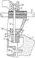
参照图2,支撑架21可通过螺钉21B可保持在与工作台组件11相对的适当位置。支撑架21优选地支撑斜角锁定组件30。斜角锁定组件30优选地包括一与工作台组件11的法兰11F相连接的主体31。杆32与主体31螺纹啮合。杆32优选地通过支撑架21延伸直至穿过支撑架21的顶部。手柄33H可连接到杆32上。Referring to FIG. 2 , the
可替换的是,杆32可固定在主体31的一端,并且与连接在手柄33H上的螺母33螺纹连接。本领域技术人员可认识到螺母33可以是六角接头,以允许在磨损的情况下回复原位。因此,通过旋转手柄33H,主体31向上运动与法兰11F锁定连接。Alternatively, the
为了保持杆32的正确同心性,可优选地提供一推动杆32与支撑架21滑动连接的夹具35。In order to maintain the correct concentricity of the
杆32可延伸穿过安装在支撑架21的肋上的垫圈34。为了使夹紧力分布到支撑架21上,杆32可包括一个与垫圈34接触的台肩32S。The
图3所示为斜角锁定组件30的第二实施例,其中相同的附图标记表示相同的部件。前面实施例的内容一同作为参考。A second embodiment of a
在此实施例中,轴11S通过销11SP固定连接到工作台组件11上,轴11S穿过支撑架21。支撑架21优选地接收锥形体36C。锥形体36C优选的是由粉末金属制造。In this embodiment, the shaft 11S is fixedly connected to the
一个或多个垫圈36W可设置在靠近锥形体36C的轴11S上。螺母36N可与轴11S螺纹啮合,将垫圈36W夹在锥形体36C与螺母36N中间。本领域技术人员可认识到,螺母36N将优选地防止支撑架21与工作台11的分离。One or more washers 36W may be provided on the shaft 11S adjacent the cone 36C. Nut 36N is threadably engageable with shaft 11S, sandwiching washer 36W between cone 36C and nut 36N. Those skilled in the art will appreciate that the nut 36N will preferably prevent separation of the
一凹垫圈37C也可设置在轴11S上和螺母36N的周围,与锥形体36C接触。杆32可设置在垫圈37C的相邻和/或相对位置。垫圈37W优选地设置在轴11S上,将杆32夹在垫圈37C,37W之间。螺母37N优选地与轴11S螺纹啮合,并保持垫圈37C在轴11S上。A concave washer 37C may also be provided on the shaft 11S and around the nut 36N, in contact with the cone 36C.
使用该装置,用户可通过旋转手柄33H,带动凸轮32C与垫圈37接触,推动锥形体36C(因而推动支撑架21)与工作台11锁定接触。本领域技术人员可认识到,此装置可优选地消除支撑架21和工作台11之间的所有空隙。Using this device, the user can rotate the
优选的是,垫圈11W设置在工作台11和支撑架21之间。垫圈11W优选的是用黄铜制造,因而工作台11和支撑架21(二者可由铝制造)不直接接触,因此可防止锁定。这种垫圈11W也可以减少润滑脂的用量,从而改善锁定功能。Preferably, the washer 11W is disposed between the table 11 and the
参照图4至5,优选地提供了一带有斜角止动装置40的斜切锯100。斜角止动装置40优选地包括一元件41,该元件可与支撑架21枢轴连接。元件41可与凹槽43N啮合,该凹槽在预定的倾斜斜角位置处设置在至少一块平板43上(优选的是三块平板43)。4 to 5, a miter saw 100 with a
一块或多块平板43可通过一个或多个与法兰11P螺纹啮合的螺钉43B连接在工作台的法兰11P上。一块或多块平板43可包括一个或多个槽43S,该槽允许在紧固螺钉43B之前调整平板43。这种调整允许用户精细地调整到预定的斜角位置。One or
本领域技术人员可认识到,为了分别调整不同的斜角,可优选地配备多块调整平板43。例如,只要每个角度的凹槽设置在不同的平板43上,可单独调整包含零度角凹槽43N的平板43,而不影响包含45度角的凹槽43N的平板。Those skilled in the art can recognize that, in order to adjust different inclination angles respectively, it is preferable to equip multiple adjusting
杆42可连接在元件41上。杆42包括一圆形把手42K,使用这种装置时,用户可向下推动把手42K,使杆42向下运动,带动元件41从与凹槽43N啮合的第一位置移动到绕过凹槽43N的第二位置。然后,用户可改变支撑架21的斜交斜角位置(因此改变锯组件20的斜角位置)。A
一弹簧44可设置在支撑架21中,以朝向第一位置偏置元件41。A
本领域技术人员可认识到,杆42可与元件41完整地形成一体。在此情况下,元件41不需要与支撑架21枢轴连接,就可允许用户在第一位置和第二位置之间联合移动杆42和元件41。Those skilled in the art will appreciate that the
图6至7示出了斜角止动组件40的第二实施例,其中相同的附图标记表示相同的元件。前面实施例的内容一同作为参考。A second embodiment of the
第一实施例和第二实施例之间主要存在三点不同。第一,元件41可被设置在弹簧板41S上,该弹簧板优选地螺钉连接或固定到支撑架21上。弹簧板41S优选地向啮合凹槽43N的第一位置偏置元件41。There are mainly three points of difference between the first embodiment and the second embodiment. First, the
第二,凸轮组件46可用来在第一位置和第二位置之间移动元件41,而不是用杆42。凸轮组件46可包括设置在元件41下面的凸轮46C。凸轮46C可连接到设置在支撑架21的外面的手柄46H上。因此,用户可优选地旋转手柄46H,带动凸轮46C旋转,解除元件41和凹槽43N的啮合。本领域技术人员可认识到,凸轮46C优选地与两个手柄46H连接,每个手柄被设置在支撑架21的每一侧。Second, a cam assembly 46 can be used to move the
第三,与前面实施例相似,至少一块平板43可包括一槽43S,以提供凹槽43N的可调整性。某些平板43的槽也可用孔来代替,同时法兰11P可包括槽11PS。如图7所示,螺钉43B可穿过平板43、槽11PS(因而穿过法兰11P)、垫圈43N并与螺母43BN螺纹啮合。本领域技术人员可认识到,这样的平板43可通过沿着槽11PS移动螺钉43B进行调整。这种调整也可通过旋转螺杆47和沿着槽11PS推动螺钉43B实现,该螺杆47优选地与法兰11P螺纹啮合并与螺钉43B接触。Third, similar to the previous embodiments, at least one
图8示出了斜角止动组件40的第三实施例,其中相同的附图标记表示相同的部件。前面实施例的内容一同作为参考。FIG. 8 shows a third embodiment of a
与前述实施例之间的主要不同是,元件48包括与棘爪凹槽43N啮合的棘爪48D。元件48优选地通过螺钉48B固定到支撑架21上。棘爪48D优选地与棘爪凹槽43N紧密啮合。The main difference between the previous embodiments is that the
元件48可包括可容纳杆42穿过的槽48C。元件48可包括一凸轮部分48CC,该凸轮部分与杆42上的凸轮面42CS接触。用这种装置时,用户可向下移动圆形把手42K(因而移动杆42)。当凸轮面42CS接触凸轮部分48CC时,凸轮部分48CC(因而棘爪48D)朝向支撑架21移动,因此解除了与棘爪凹槽43N的啮合。
本领域技术人员可认识到,为了朝向第一位置即与棘爪凹槽43N啮合的位置偏置棘爪48D,元件48的各部分可由弹性材料例如弹簧钢制造。Those skilled in the art will recognize that to bias the
图9示出了斜角止动组件40的第四实施例,其中相同的附图标记表示相同的部件。前面实施例的内容一同作为参考。FIG. 9 shows a fourth embodiment of a
与前面实施例的主要不同在于,棘爪48D从前方与棘爪凹槽43N啮合。当用户向下移动圆形把手42K(因而移动杆42)时,链环49可朝向元件48移动。当凸轮面42CS与链环49接触时,链环49与元件48接触并移动元件48(因此移动棘爪48D)离开支撑架21,因此解除与棘爪凹槽43N的啮合。The main difference from the previous embodiment is that the
本领域技术人员可认识到,可以对在此所公开的装置进行其它附加或替换。但是,所有这些附加和/或替换均被认为是本发明的等同物。Those skilled in the art will recognize that other additions or substitutions may be made to the devices disclosed herein. However, all such additions and/or substitutions are considered equivalents of the present invention.
Claims (18)
Applications Claiming Priority (2)
| Application Number | Priority Date | Filing Date | Title |
|---|---|---|---|
| US67603705P | 2005-04-29 | 2005-04-29 | |
| US60/676,037 | 2005-04-29 |
Publications (2)
| Publication Number | Publication Date |
|---|---|
| CN1872468A CN1872468A (en) | 2006-12-06 |
| CN1872468Btrue CN1872468B (en) | 2010-06-02 |
Family
ID=36693079
Family Applications (1)
| Application Number | Title | Priority Date | Filing Date |
|---|---|---|---|
| CN2006100998511AExpired - Fee RelatedCN1872468B (en) | 2005-04-29 | 2006-04-29 | Miter Lock Assembly for Miter Saws |
Country Status (6)
| Country | Link |
|---|---|
| US (3) | US20060243113A1 (en) |
| EP (1) | EP1716986A1 (en) |
| JP (1) | JP2006306103A (en) |
| CN (1) | CN1872468B (en) |
| AU (1) | AU2006201714A1 (en) |
| CA (1) | CA2544212A1 (en) |
Families Citing this family (20)
| Publication number | Priority date | Publication date | Assignee | Title |
|---|---|---|---|---|
| DE102006059752B4 (en)* | 2006-12-18 | 2016-05-04 | Festool Gmbh | Inclined swiveling saw |
| US7958641B1 (en)* | 2007-05-09 | 2011-06-14 | Woodman Tools, Llc | Rolling plate assembly attachment for portable power cutting tools including an improved structural design and manufactured out of improved materials, an improved wheel configuration, and an adjustable bevel gear and a cutting guide |
| US8695468B2 (en)* | 2007-10-30 | 2014-04-15 | Robert Bosch Gmbh | Locking assembly for a power miter saw |
| US8359959B2 (en) | 2008-01-08 | 2013-01-29 | Makita Corporation | Cutting devices |
| JP5259299B2 (en)* | 2008-01-08 | 2013-08-07 | 株式会社マキタ | Inclination positioning mechanism of cutting machine body in tabletop cutting machine |
| US8002253B2 (en)* | 2008-06-20 | 2011-08-23 | Robert Bosch Gmbh | Button actuated detent system |
| US8250956B2 (en)* | 2009-04-28 | 2012-08-28 | Robert Bosch Gmbh | Miter saw with work surface extensions |
| CN101987379B (en)* | 2009-07-30 | 2013-01-30 | 苏州宝时得电动工具有限公司 | Oblique saw |
| US8931386B2 (en)* | 2010-12-23 | 2015-01-13 | Robert Bosch Gmbh | Miter saw with bevel lock |
| JP5989552B2 (en)* | 2013-01-21 | 2016-09-07 | 株式会社マキタ | Tabletop cutting machine |
| WO2015094853A1 (en) | 2013-12-16 | 2015-06-25 | Robert Bosch Gmbh | Miter saw including front accessible bevel lock system |
| CN208195813U (en) | 2015-02-25 | 2018-12-07 | 米沃奇电动工具公司 | Mitre saw |
| US9833849B2 (en) | 2016-01-18 | 2017-12-05 | Tti (Macao Commercial Offshore) Limited | Miter saw |
| US10245750B2 (en) | 2016-04-20 | 2019-04-02 | Duncan R. Everhart | Compound miter apparatus |
| CN105835106A (en)* | 2016-04-25 | 2016-08-10 | 刘影 | Rotary-cutting machining device for wood-plastic composite board |
| US10286463B2 (en) | 2016-12-27 | 2019-05-14 | Robert Bosch Tool Corporation | Bevel locking system |
| US20180185936A1 (en)* | 2016-12-30 | 2018-07-05 | Robert Bosch Tool Corporation | Detent Mechanism with Separately Adjustable Detents |
| US10710267B2 (en) | 2017-07-10 | 2020-07-14 | Milwaukee Electric Tool Corporation | Miter saw |
| TWI656931B (en)* | 2018-02-01 | 2019-04-21 | 力山工業股份有限公司 | A foldable miter saw |
| TWI852535B (en)* | 2023-05-05 | 2024-08-11 | 力山工業股份有限公司 | Saw with a control handle having three-stage adjustment function |
Citations (3)
| Publication number | Priority date | Publication date | Assignee | Title |
|---|---|---|---|---|
| CN1158775A (en)* | 1995-08-10 | 1997-09-10 | 密尔沃基电力工具公司 | Indexing override mechanism for slide compound miter saw |
| US20040089125A1 (en)* | 2002-11-08 | 2004-05-13 | Emerson Electric Co. | Compound miter saw |
| EP0857550B1 (en)* | 1997-02-11 | 2008-05-14 | Black & Decker Inc. | Bevel locking system for a sliding compound miter saw |
Family Cites Families (25)
| Publication number | Priority date | Publication date | Assignee | Title |
|---|---|---|---|---|
| US834206A (en)* | 1905-09-15 | 1906-10-23 | Washington C Kantner | Mitering-machine. |
| US4011782A (en)* | 1975-09-25 | 1977-03-15 | The Black And Decker Manufacturing Company | Power miter saw |
| US4226152A (en)* | 1979-05-29 | 1980-10-07 | The Stanley Works | Saw guide subassembly for mitre box |
| US4454793A (en)* | 1982-04-16 | 1984-06-19 | Donald Strong | Attachment for a miter gauge |
| US5235889A (en)* | 1992-03-25 | 1993-08-17 | Delta International Machinery Corp. | Compound miter saw |
| US5495784A (en)* | 1994-09-29 | 1996-03-05 | Chen; Ruey-Zon | Cutting depth setting device for a saw machine |
| GB9526374D0 (en)* | 1995-12-22 | 1996-02-21 | Black & Decker Inc | A chop/slide saw |
| US5778752A (en)* | 1996-12-27 | 1998-07-14 | Rexon Industrial Corp., Ltd. | Scroll saw having a tiltable table and positive stops for select angular positions of the table |
| TW467783B (en)* | 1998-02-13 | 2001-12-11 | Black & Amp Decker Inc | Table saw |
| CN1191907C (en)* | 1998-03-11 | 2005-03-09 | 布莱克和戴克公司 | Sliding saw |
| US6672190B2 (en)* | 2000-05-03 | 2004-01-06 | Taylor Design Group, Inc. | Precision miter gauge |
| US7021186B2 (en)* | 2001-08-10 | 2006-04-04 | Eastway Fair Company Limited | Bevel adjustment mechanism for a compound miter saw |
| US7127977B2 (en)* | 2002-02-11 | 2006-10-31 | Porter-Cable/Delta | Remotely actuated beveling systems for a miter saw |
| TW542083U (en)* | 2002-05-15 | 2003-07-11 | Ruei-Sen Liau | Angle adjustment apparatus for wire saw machine |
| US7018022B2 (en)* | 2002-06-12 | 2006-03-28 | Sharp Kabushiki Kaisha | Inkjet printhead and inkjet image apparatus |
| US6758123B2 (en)* | 2002-10-16 | 2004-07-06 | S-B Power Tool Corporation | Bevel angle detent system for a compound miter saw |
| US20040112190A1 (en)* | 2002-11-26 | 2004-06-17 | Hollis Michael Chad | Bevel angle locking actuator and bevel angle locking system for a saw |
| US8272133B2 (en)* | 2003-07-03 | 2012-09-25 | Robert Bosch Gmbh | Circular saw having bevel and depth of cut detent system |
| JP4534549B2 (en)* | 2004-03-26 | 2010-09-01 | 日立工機株式会社 | Tabletop cutting machine |
| RU2308359C2 (en)* | 2004-09-02 | 2007-10-20 | Хитачи Коки Ко., Лтд. | Machine tool for cutting by angle (variants) |
| TWI341781B (en)* | 2004-09-03 | 2011-05-11 | Black & Decker Inc | Trunnion assembly for saws |
| US20060053762A1 (en)* | 2004-09-16 | 2006-03-16 | Stover Dale A | Walk-behind implement and handle system for use with same |
| JP4759276B2 (en)* | 2005-01-20 | 2011-08-31 | 日立工機株式会社 | Tabletop cutting machine |
| JP4552873B2 (en)* | 2006-03-08 | 2010-09-29 | 日立工機株式会社 | Tabletop cutting machine |
| US8776656B2 (en)* | 2008-07-22 | 2014-07-15 | Gerhard Weusthof | Circular and miter box saw |
- 2006
- 2006-04-18USUS11/406,125patent/US20060243113A1/ennot_activeAbandoned
- 2006-04-20CACA 2544212patent/CA2544212A1/ennot_activeAbandoned
- 2006-04-24EPEP20060113000patent/EP1716986A1/ennot_activeWithdrawn
- 2006-04-24AUAU2006201714Apatent/AU2006201714A1/ennot_activeAbandoned
- 2006-04-28JPJP2006125977Apatent/JP2006306103A/ennot_activeWithdrawn
- 2006-04-29CNCN2006100998511Apatent/CN1872468B/ennot_activeExpired - Fee Related
- 2009
- 2009-04-07USUS12/419,350patent/US8960063B2/enactiveActive
- 2015
- 2015-01-12USUS14/594,364patent/US9511428B2/enactiveActive
Patent Citations (3)
| Publication number | Priority date | Publication date | Assignee | Title |
|---|---|---|---|---|
| CN1158775A (en)* | 1995-08-10 | 1997-09-10 | 密尔沃基电力工具公司 | Indexing override mechanism for slide compound miter saw |
| EP0857550B1 (en)* | 1997-02-11 | 2008-05-14 | Black & Decker Inc. | Bevel locking system for a sliding compound miter saw |
| US20040089125A1 (en)* | 2002-11-08 | 2004-05-13 | Emerson Electric Co. | Compound miter saw |
Also Published As
| Publication number | Publication date |
|---|---|
| EP1716986A1 (en) | 2006-11-02 |
| US20090249933A1 (en) | 2009-10-08 |
| US20060243113A1 (en) | 2006-11-02 |
| US20150183035A1 (en) | 2015-07-02 |
| AU2006201714A1 (en) | 2006-11-16 |
| JP2006306103A (en) | 2006-11-09 |
| US9511428B2 (en) | 2016-12-06 |
| CN1872468A (en) | 2006-12-06 |
| CA2544212A1 (en) | 2006-10-29 |
| US8960063B2 (en) | 2015-02-24 |
Similar Documents
| Publication | Publication Date | Title |
|---|---|---|
| CN1872468B (en) | Miter Lock Assembly for Miter Saws | |
| CN100464913C (en) | Tool-less adjustable base for a portable saw | |
| EP2217399B1 (en) | A miter lock assembly for miter saws | |
| US8096220B2 (en) | Modular table saw guarding system upper guard barrier | |
| US7114425B2 (en) | Fine-adjustment mechanism to preset a miter saw for precision miter cuts | |
| US9216485B2 (en) | Quick clamping device adapted for worktable | |
| EP2050547B1 (en) | A miter saw with an adjustable fence | |
| US7546791B2 (en) | Saw blade lifting mechanism for sawing machine | |
| EP2156930B1 (en) | Mitre saw comprising a fence which is automatically adjusted | |
| CN100445006C (en) | Miter saw | |
| US6615701B2 (en) | Bevel stop for cutting device | |
| US20090315237A1 (en) | Button actuated detent system | |
| US10046476B2 (en) | Table saw riving knife mounting arrangement | |
| US8322261B2 (en) | Locking construction for a miter saw having a hinged linear guide mechanism | |
| US4454898A (en) | Router bracket | |
| US20190232520A1 (en) | Linear guide mechanism and hinge connections of power miter saw | |
| US10029323B2 (en) | Adjustable work table | |
| CA2736715C (en) | Docking and miter saw having an inset preferably delimiting a saw slot | |
| EP1818144B1 (en) | Bevel lock assembly for miter saws | |
| JP2010201882A (en) | Portable cutter | |
| US20190210241A1 (en) | Linear guide mechanism of power miter saw | |
| US20240051044A1 (en) | Hacksaw | |
| JP2010201883A (en) | Portable cutter | |
| US9987693B2 (en) | Table saw having a blade height adjustment mechanism |
Legal Events
| Date | Code | Title | Description |
|---|---|---|---|
| C06 | Publication | ||
| PB01 | Publication | ||
| C10 | Entry into substantive examination | ||
| SE01 | Entry into force of request for substantive examination | ||
| C14 | Grant of patent or utility model | ||
| GR01 | Patent grant | ||
| CF01 | Termination of patent right due to non-payment of annual fee | ||
| CF01 | Termination of patent right due to non-payment of annual fee | Granted publication date:20100602 Termination date:20190429 |