Movatterモバイル変換


[0]ホーム

URL:


CN1866147A - Fan control device and method - Google Patents

Fan control device and method
Download PDF

Info

Publication number
CN1866147A
CN1866147ACNA2005100726832ACN200510072683ACN1866147ACN 1866147 ACN1866147 ACN 1866147ACN A2005100726832 ACNA2005100726832 ACN A2005100726832ACN 200510072683 ACN200510072683 ACN 200510072683ACN 1866147 ACN1866147 ACN 1866147A
Authority
CN
China
Prior art keywords
signal
speed
temperature
fan
target
Prior art date
Legal status (The legal status is an assumption and is not a legal conclusion. Google has not performed a legal analysis and makes no representation as to the accuracy of the status listed.)
Granted
Application number
CNA2005100726832A
Other languages
Chinese (zh)
Other versions
CN1866147B (en
Inventor
谢宗融
林侑良
黄跃龙
蔡明熹
Current Assignee (The listed assignees may be inaccurate. Google has not performed a legal analysis and makes no representation or warranty as to the accuracy of the list.)
Delta Electronics Inc
Original Assignee
Delta Electronics Inc
Priority date (The priority date is an assumption and is not a legal conclusion. Google has not performed a legal analysis and makes no representation as to the accuracy of the date listed.)
Filing date
Publication date
Application filed by Delta Electronics IncfiledCriticalDelta Electronics Inc
Priority to CN2005100726832ApriorityCriticalpatent/CN1866147B/en
Publication of CN1866147ApublicationCriticalpatent/CN1866147A/en
Application grantedgrantedCritical
Publication of CN1866147BpublicationCriticalpatent/CN1866147B/en
Anticipated expirationlegal-statusCritical
Expired - Lifetimelegal-statusCriticalCurrent

Links

Images

Landscapes

Abstract

A fan control device receives a target rotating speed signal to control the rotating speed of a fan, and comprises a temperature measuring module, a rotating speed modulating module and a fan driving module, wherein the temperature measuring module measures the temperature of the environment where the fan is located to generate a temperature value, the rotating speed modulating module is electrically connected with the temperature measuring module and receives the temperature value, and generates a fan control signal according to the temperature value and the target rotating speed signal, and the fan driving module is electrically connected with the rotating speed modulating module and generates a driving signal according to the fan control signal to drive the fan to act. In addition, the invention also provides a fan control method which can be applied to the fan control device.

Description

Translated fromChinese
风扇控制装置及方法Fan control device and method

技术领域technical field

本发明涉及一种风扇控制装置及方法。The invention relates to a fan control device and method.

背景技术Background technique

风扇是装设在多数的电子装置中,以利各类型的电子装置能够顺利地散热。现有风扇控制装置是可依据风扇的环境适当地依据环境温度将风扇的转速固定为全速或低速,或者是将风扇转速调整在全速与低速之间。Fans are installed in most electronic devices, so that various types of electronic devices can dissipate heat smoothly. The existing fan control device can properly fix the fan speed at full speed or low speed according to the environment temperature of the fan, or adjust the fan speed between full speed and low speed.

如图1所示,现有的一风扇控制装置1是包括一温度传感器11与一驱动芯片12,该温度传感器11是测量一环境温度并产生一测量值111,该驱动芯片12是依据该测量值111或一低限转速信号121产生一驱动信号122,一风扇2是接收该驱动信号122而动作,其中该驱动信号122可以是一脉冲宽度调制信号,该低限转速信号121可以是一固定电压电平,该风扇2是可由该驱动信号122的电压值高低或是电压脉冲之间的宽幅比例而调整转速。As shown in FIG. 1 , an existingfan control device 1 includes atemperature sensor 11 and adriver chip 12. Thetemperature sensor 11 measures an ambient temperature and generates a measuredvalue 111. Thedriver chip 12 is based on themeasurement A value 111 or a low-limitrotational speed signal 121 generates adriving signal 122, and afan 2 operates upon receiving thedriving signal 122, wherein thedriving signal 122 can be a pulse width modulation signal, and the low-limitrotational speed signal 121 can be a fixed Voltage level, the speed of thefan 2 can be adjusted by the voltage value of thedriving signal 122 or the width ratio between voltage pulses.

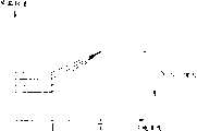
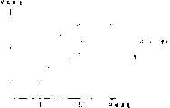
上述该温度传感器11可以是一热敏电阻器,如图2所示,当该环境温度越高时,该温度传感器11产生的该测量值111的电压越低。The above-mentionedtemperature sensor 11 may be a thermistor, as shown in FIG. 2 , when the ambient temperature is higher, the voltage of the measuredvalue 111 generated by thetemperature sensor 11 is lower.

如图1与图3所示,该风扇2是因该驱动信号122的电压值高低或是电压脉冲之间的宽幅比例而调整转速,而该驱动信号122又随该测量值111的大小而改变,因此该风扇2可随时反应该环境温度而调整风扇转速。As shown in FIG. 1 and FIG. 3 , the speed of thefan 2 is adjusted according to the voltage value of thedriving signal 122 or the width ratio between the voltage pulses, and thedriving signal 122 is adjusted according to the magnitude of the measuredvalue 111. Therefore, thefan 2 can adjust the fan speed in response to the ambient temperature at any time.

当该环境温度大于一温度T1且小于一温度T2时,该驱动芯片12是依据该测量值111调整该驱动信号122的电压值或电压脉冲间的宽幅比例,使得该风扇2得以随温度变化调整转速。When the ambient temperature is greater than a temperatureT1 and less than a temperatureT2 , thedrive chip 12 adjusts the voltage value of thedrive signal 122 or the width ratio between voltage pulses according to the measuredvalue 111, so that thefan 2 can follow the Temperature changes adjust the speed.

当该环境温度大于该温度T2时,该驱动芯片12是维持该驱动信号122的电压值或电压脉冲间的宽幅比例而不再随该测量值111调整,使得该风扇2以全速运转不再随温度增加而增加转速。When the ambient temperature is greater than the temperatureT2 , thedrive chip 12 maintains the voltage value of thedrive signal 122 or the width ratio between the voltage pulses and no longer adjusts with the measuredvalue 111, so that thefan 2 cannot run at full speed. Then increase the speed as the temperature increases.

当该环境温度小于该温度T1时,该驱动芯片12是依据该低限转速信号121产生该驱动信号122,该驱动信号122的电压值或电压脉冲间的宽幅比例而不再随该测量值111调整,使得该风扇2维持低速运转不再随温度降低而降低转速。When the ambient temperature is lower than the temperatureT1 , thedrive chip 12 generates thedrive signal 122 according to the low-limitrotational speed signal 121, and the voltage value of thedrive signal 122 or the width ratio between voltage pulses no longer follows the measured Thevalue 111 is adjusted so that thefan 2 maintains low-speed operation and no longer reduces the rotation speed as the temperature decreases.

然而,现有的风扇控制装置及方法仅能够随温度变化而调整风扇的转速,所以使用者无法自行降低风扇转速以减低风扇噪音,亦无法视散热或通风等需求自行调整风扇转速。也就是说,以现有的风扇控制装置及方法仅可依照温度变化而调整风扇转速,风扇的转速与温度之间是保持一固定关系,所以风扇转速与温度的特性曲线是无法做更进一步的变化,因此风扇在固定的温度下是维持固定的转速而无法产生不同的转速,所以无法视使用者需求或环境需要在固定的温度下调整风扇转速。However, the existing fan control device and method can only adjust the speed of the fan according to temperature changes, so the user cannot reduce the speed of the fan to reduce the noise of the fan, nor can the user adjust the speed of the fan according to the needs of heat dissipation or ventilation. That is to say, the existing fan control device and method can only adjust the fan speed according to the temperature change, and there is a fixed relationship between the fan speed and temperature, so the characteristic curve of the fan speed and temperature cannot be further improved. Therefore, the fan maintains a fixed speed at a fixed temperature and cannot generate different speeds, so it is impossible to adjust the fan speed at a fixed temperature according to user needs or environmental needs.

因此,本发明乃提供一种风扇控制装置及方法,以期不仅能够除依据温度自动调整风扇转速,更能够依据使用者设定而自动调整风扇转速,以依使用者需求或视环境需要在各温度情况下调增或减少风扇转速,使得风扇转速与温度的特性曲线能够更进一步变化,正是当前的重要课题之一。Therefore, the present invention provides a fan control device and method, in order not only to automatically adjust the fan speed according to the temperature, but also to automatically adjust the fan speed according to the user's setting, so as to adjust the fan speed according to the user's needs or depending on the environment. It is one of the current important issues to increase or decrease the fan speed under certain circumstances so that the characteristic curve of the fan speed and temperature can be further changed.

发明内容Contents of the invention

有鉴于上述课题,本发明的目的为提供一种能够自动调整风扇转速的风扇控制装置及方法。In view of the above problems, the purpose of the present invention is to provide a fan control device and method capable of automatically adjusting the rotation speed of the fan.

缘是,为达上述目的,依本发明的风扇控制装置是接收一目标转速信号以控制一风扇的转速,此装置包括一温度测量模块、一转速调制模块与一风扇驱动模块,其中该温度测量模块是测量该风扇所处环境的温度以产生一温度值,该转速调制模块是与该温度测量模块电连接并接收该温度值,且依据该温度值与该目标转速信号以产生一风扇控制信号,该风扇驱动模块是与该转速调制模块电连接,并依据该风扇控制信号产生一驱动信号以驱动该风扇动作。The reason is that, in order to achieve the above purpose, the fan control device according to the present invention receives a target speed signal to control the speed of a fan. This device includes a temperature measurement module, a speed modulation module and a fan drive module, wherein the temperature measurement The module measures the temperature of the environment where the fan is located to generate a temperature value, the rotational speed modulation module is electrically connected to the temperature measurement module and receives the temperature value, and generates a fan control signal according to the temperature value and the target rotational speed signal , the fan driving module is electrically connected with the rotational speed modulation module, and generates a driving signal according to the fan control signal to drive the fan to act.

为达上述目的,依本发明的风扇控制方法是接收一目标转速信号以控制一风扇的转速,本方法包括测量该风扇所处环境的温度以产生一温度值,然后依据该温度值与该目标转速信号以产生一风扇控制信号,以及依据该风扇控制信号产生一驱动信号以驱动该风扇动作。In order to achieve the above object, the fan control method according to the present invention is to receive a target speed signal to control the speed of a fan. The method includes measuring the temperature of the environment where the fan is located to generate a temperature value, and then according to the temperature value and the target The rotation speed signal is used to generate a fan control signal, and a driving signal is generated according to the fan control signal to drive the fan to operate.

承上所述,因依本发明的风扇控制装置是具有转速调制模块,转速调制模块是依据温度值与目标转速信号控制风扇的转速,故能够除依据温度值自动调节风扇转速,更能够依据目标转速信号而自动调节风扇转速,使得风扇转速与温度的特性曲线能够更进一步变化,风扇得以更依据使用者的环境及需求而适当适切地调整风扇转速。Based on the above, because the fan control device according to the present invention has a speed modulation module, the speed modulation module controls the speed of the fan according to the temperature value and the target speed signal, so it can not only automatically adjust the fan speed according to the temperature value, but also according to the target speed. The speed signal automatically adjusts the fan speed, so that the characteristic curve of the fan speed and temperature can be further changed, and the fan can adjust the fan speed more appropriately according to the user's environment and needs.

附图说明Description of drawings

图1为显示现有风扇控制装置的示意图;FIG. 1 is a schematic diagram showing a conventional fan control device;

图2为显示现有风扇控制装置的风扇转速与环境温度的曲线关系图;FIG. 2 is a graph showing the relationship between the fan speed and the ambient temperature in the conventional fan control device;

图3为显示现有风扇控制装置的温度传感器输出信号与环境温度的曲线关系图;3 is a graph showing the relationship between the output signal of the temperature sensor and the ambient temperature of the existing fan control device;

图4为显示依本发明较佳实施例的风扇控制装置的示意图;4 is a schematic diagram showing a fan control device according to a preferred embodiment of the present invention;

图5为显示依本发明较佳实施例的风扇控制装置的转速调制模块的示意图;5 is a schematic diagram showing a rotational speed modulation module of a fan control device according to a preferred embodiment of the present invention;

图6为显示依本发明较佳实施例的风扇控制装置的速限调整单元的示意图;6 is a schematic diagram showing a speed limit adjustment unit of a fan control device according to a preferred embodiment of the present invention;

图7A-7G为显示依本发明较佳实施例的风扇控制装置的风扇转速与环境温度的曲线关系图;7A-7G are graphs showing the relationship between the fan speed and the ambient temperature of the fan control device according to a preferred embodiment of the present invention;

图8为显示依本发明较佳实施例的风扇控制装置的电路示意图;8 is a schematic circuit diagram showing a fan control device according to a preferred embodiment of the present invention;

图9为显示依本发明较佳实施例的风扇控制方法的流程图;FIG. 9 is a flowchart showing a fan control method according to a preferred embodiment of the present invention;

图10为显示依本发明较佳实施例的风扇控制方法的流程图,其说明依据温度值与目标转速信号以产生风扇控制信号的步骤;以及10 is a flowchart showing a fan control method according to a preferred embodiment of the present invention, which illustrates the steps of generating a fan control signal according to a temperature value and a target speed signal; and

图11为显示依本发明较佳实施例的风扇控制方法的流程图,其说明依据目标转速信号与温度转速信号产生第二速限信号的步骤。FIG. 11 is a flowchart showing a fan control method according to a preferred embodiment of the present invention, which illustrates the steps of generating a second speed limit signal according to a target speed signal and a temperature speed signal.

附图符号说明Description of reference symbols

1:风扇控制装置1: Fan control unit

11:温度传感器11: Temperature sensor

111:测量值111: measured value

12:驱动芯片12: Driver chip

121:低限转速信号121: Low speed limit signal

122:驱动信号122: Drive signal

2:风扇2: fan

3:风扇控制装置3: Fan control unit

31:温度测量模块31: Temperature measurement module

32:风扇驱动模块32: Fan driver module

4:风扇4: fan

5:转速调制模块5: Speed modulation module

51:温度调制单元51: Temperature modulation unit

52:第一定速调制单元52: The first constant speed modulation unit

53:综合控制单元53: Integrated control unit

54:第二定速调制单元54: The second constant speed modulation unit

55:速限调整单元55: Speed limit adjustment unit

C1-C3:电容器C1 -C3 : Capacitors

D1-D8:二极管D1 -D8 : Diodes

R1-R14:电阻器R1 -R14 : Resistors

Rt:热敏电阻器Rt : Thermistor

SET1:第一温度设定SET1 : the first temperature setting

SET2:第二温度设定SET2 : second temperature setting

Sdrive:驱动信号Sdrive : drive signal

Sfan:风扇控制信号Sfan : fan control signal

Starget:目标转速信号Starget : target speed signal

Stemp:温度值Stemp : temperature value

S51:温度转速信号S51 : temperature speed signal

S52:第一速限信号S52 : The first speed limit signal

S53:第二速限信号S53 : Second speed limit signal

S54:温度速限信号S54 : temperature speed limit signal

S55:第一目标信号S55 : first target signal

S56:第二目标信号S56 : Second target signal

S57:第三目标信号S57 : Third target signal

TR1-TR3:晶体管TR1 -TR3 : Transistors

T1-T2:温度T1 -T2 : temperature

V:外接电源V: external power supply

Step1-Step6:风扇控制方法Step1-Step6: Fan Control Method

Step21-Step23:风扇控制方法Step21-Step23: Fan Control Method

具体实施方式Detailed ways

以下将参照附图,说明依本发明较佳实施例的风扇控制装置及方法。The fan control device and method according to preferred embodiments of the present invention will be described below with reference to the accompanying drawings.

如图4所示,依本发明较佳实施例的风扇控制装置3是接收一目标转速信号Starget以控制一风扇4的转速,该风扇控制装置3包括一温度测量模块31、一转速调制模块5与一风扇驱动模块32。As shown in Figure 4, thefan control device 3 according to the preferred embodiment of the present invention receives a target speed signal Starget to control the speed of a fan 4, thefan control device 3 includes atemperature measurement module 31, aspeed modulation module 5 and afan drive module 32.

该温度测量模块31是测量该风扇4所处环境的温度以产生一温度值Stemp,该转速调制模块5是与该温度测量模块31电连接并接收该温度值Stemp,且依据该温度值Stemp与该目标转速信号Starget以产生一风扇控制信号Sfan,该风扇驱动模块32是与该转速调制模块5电连接,并依据该风扇控制信号Sfan产生一驱动信号Sdrive以驱动该风扇4动作。在本实施例中,该目标转速信号Starget与该驱动信号Sdrive是可为脉冲宽度调制信号(Pulse Width ModulationSignal)。该目标转速信号Starget是可由其它温度控制组件所产生,例如主机板上的温度监控芯片,或PWM控制芯片,或是微处理机所产生的数字输出等等。Thetemperature measurement module 31 measures the temperature of the environment where the fan 4 is located to generate a temperature value Stemp , the rotationalspeed modulation module 5 is electrically connected to thetemperature measurement module 31 and receives the temperature value Stemp , and according to the temperature value Stemp and the target speed signal Starget to generate a fan control signal Sfan , thefan drive module 32 is electrically connected to thespeed modulation module 5, and generates a drive signal Sdrive according to the fan control signal Sfan to drive the fan. Fan 4 operates. In this embodiment, the target rotational speed signal Starget and the driving signal Sdrive may be pulse width modulation signals (Pulse Width Modulation Signal). The target speed signal Starget can be generated by other temperature control components, such as a temperature monitoring chip on the motherboard, or a PWM control chip, or a digital output generated by a microprocessor.

如图5所示,在本实施例中,该转速调制模块5包括一温度调制单元51、一第一定速调制单元52与一综合控制单元53。As shown in FIG. 5 , in this embodiment, the rotationalspeed modulation module 5 includes atemperature modulation unit 51 , a first constantspeed modulation unit 52 and anintegrated control unit 53 .

该温度调制单元51是接收该温度值Stemp并依据该温度值Stemp与该目标转速信号Starget以产生一温度转速信号S51,该第一定速调制单元52是依据该目标转速信号Starget产生一第一速限信号S52,该综合控制单元53是依据该温度转速信号S51与该第一速限信号S52至少二者其中之一以产生该风扇控制信号SfanThetemperature modulation unit 51 receives the temperature value Stemp and generates a temperaturespeed signal S 51 according to the temperature value Stemp and the target speed signal Starget . The first constant speed modulation unit52 generates a temperaturespeed signal S 51 according to the target speed signal Starget generates a first speed limit signal S52 , and theintegrated control unit 53 generates the fan control signal Sfan according to at least one of the temperature speed signal S51 and the first speed limit signal S52 .

该第一定速调制单元52是依据该目标转速信号Starget与一第一温度设定SET1产生该第一速限信号S52,其中该第一温度设定SET1是指定该风扇4维持固定转速的温度范围。The first constantspeed modulation unit 52 generates the first speed limit signal S52 according to the target speed signal Starget and a first temperature setting SET1 , wherein the first temperature setting SET1 specifies that the fan 4 maintains Fixed speed temperature range.

在本实施例中,该转速调制模块5更包括一第二定速调制单元54,该第二定速调制单元54是依据一温度速限信号S54与该目标转速信号Starget产生一第二速限信号S53,其中该温度速限信号S54是由该温度调制单元51依据该温度值Stemp所产生,该风扇驱动模块32更可依据该第二速限信号S53产生该驱动信号Sdrive,该风扇4是依据该驱动信号Sdrive维持固定转速。In this embodiment, the rotationalspeed modulation module 5 further includes a second constantspeed modulation unit 54, which generates a second constantspeed modulation unit 54 according to a temperature speed limit signalS54 and the target rotational speed signal Starget . The speed limit signal S53 , wherein the temperature speed limit signal S54 is generated by thetemperature modulation unit 51 according to the temperature value Stemp , and thefan drive module 32 can further generate the drive signal according to the second speed limit signal S53 Sdrive , the fan 4 maintains a fixed speed according to the driving signal Sdrive .

另外,该第二定速调制单元54更可依据该目标转速信号Starget、该温度速限信号S54与一第二温度设定SET2产生该第二速限信号S53,其中该第二温度设定SET2是指定该风扇4维持固定转速的温度范围。In addition, the second constantspeed modulation unit 54 can further generate the second speed limit signal S53 according to the target speed signal Starget , the temperature speed limit signal S54 and a second temperature setting SET2 , wherein the second The temperature setting SET2 specifies the temperature range within which the fan 4 maintains a fixed rotation speed.

如图6所示,在本实施例中,该转速调制模块5更包括一速限调整单元55,该速限调整单元55是调整该目标转速信号Starget以产生一第一目标信号S55,一第二目标信号S56与一第三目标信号S57As shown in FIG. 6 , in this embodiment, thespeed modulation module 5 further includes a speed limit adjustment unit 55 , the speed limit adjustment unit 55 adjusts the target speed signal Starget to generate a first target signal S55 , A second target signal S56 and a third target signal S57 .

该第一定速调制单元52是依据该第一目标信号S55产生该第一速限信号S52,该温度调制单元51是依据该温度值Stemp与该第二目标信号S56产生该温度转速信号S51,该第二定速调制单元54是依据该第三目标信号S57与该温度速限信号S54产生该第二速限信号S53The first constantspeed modulation unit 52 generates the first speed limit signal S52 according to the first target signal S55 , and thetemperature modulation unit 51 generates the temperature according to the temperature value Stemp and the second target signal S56 The speed signal S51 , the second constantspeed modulation unit 54 generates the second speed limit signal S53 according to the third target signal S57 and the temperature speed limit signal S54 .

如图4、图5与图7A所示,在本实施例中,当该风扇4所处的一环境温度大于一温度T1且小于一温度T2时,该温度调制单元51是依据该温度值Stemp产生该温度转速信号S51,该综合控制单元53是依据该温度转速信号S51与该第一速限信号S52产生该风扇控制信号Sfan,该风扇驱动模块32是依据该风扇控制信号Sfan产生该驱动信号Sdrive,该风扇4经由该驱动信号Sdrive驱动之后,可依该环境温度的变化调整转速,或是依据该目标转速信号Starget调整相同该环境温度下的该风扇4的转速。在本实施例中,该目标转速信号Starget的电压值越小则该风扇4转速越高,也就是说,在固定该环境温度下,该目标转速信号Starget的电压若调增,则该风扇4的转速会降低。As shown in Figure 4, Figure 5 and Figure 7A, in this embodiment, when the ambient temperature of the fan 4 is greater than a temperatureT1 and less than a temperatureT2 , thetemperature modulation unit 51 is based on the temperature The value Stemp generates the temperature speed signal S51 , theintegrated control unit 53 generates the fan control signal Sfan according to the temperature speed signal S51 and the first speed limit signal S52 , and thefan drive module 32 generates the fan control signal S fan according to the fan The control signal Sfan generates the drive signal Sdrive , after the fan 4 is driven by the drive signal Sdrive , the speed can be adjusted according to the change of the ambient temperature, or the speed of the fan 4 under the same ambient temperature can be adjusted according to the target speed signal Starget The speed of fan 4. In this embodiment, the smaller the voltage value of the target speed signal Starget is, the higher the speed of the fan 4 is. The speed of fan 4 will decrease.

当该环境温度大于该温度T2时,该第一定速调制单元52是依据该目标转速信号Starget与该第一温度设定SET1产生该第一速限信号S52,其中该第一温度设定SET1是指定当该环境温度大于该温度T1时该风扇4维持全速运转。该综合控制单元53是依据该第一速限信号S52产生该风扇控制信号Sfan。该风扇驱动模块32是依据该风扇控制信号Sfan产生该驱动信号Sdrive,该风扇4经由该驱动信号Sdrive驱动之后,该风扇4以全速运转不再随温度增加而再增加转速,且可依据该目标转速信号Starget调整相同该环境温度下该风扇4全速运转的转速,也就是说,在固定该环境温度下,该目标转速信号Starget的电压若调增,则该风扇4的转速会降低。When the ambient temperature is greater than the temperature T2 , the first constantspeed modulation unit 52 generates the first speed limit signal S52 according to the target speed signal Starget and the first temperature setting SET1 , wherein the first The temperature setting SET1 specifies that the fan 4 maintains full-speed operation when the ambient temperature is greater than the temperature T1 . Theintegrated control unit 53 generates the fan control signal Sfan according to the first speed limit signal S52 . Thefan drive module 32 generates the drive signal Sdrive according to the fan control signal Sfan . After the fan 4 is driven by the drive signal Sdrive , the fan 4 runs at full speed and does not increase the speed with the increase of temperature, and can According to the target speed signal Starget to adjust the speed of the fan 4 running at full speed at the same ambient temperature, that is to say, at a fixed ambient temperature, if the voltage of the target speed signal Starget is increased, the speed of the fan 4 will increase. will decrease.

当该环境温度小于该温度T1时,该第二定速调制单元54是依据该目标转速信号Starget、该温度速限信号S54与该第二温度设定SET2产生该第二速限信号S53,使得该风扇4在该温度T1附近时的转速不会突然增高或降低。其中该第二温度设定SET2是指定当该环境温度小于该温度T1时该风扇4维持低速运转。此时如果该第二速限信号S53的电压电平小于该风扇控制信号Sfan的电压电平时,该风扇驱动模块32是依据该第二速限信号S53产生该驱动信号Sdrive,该风扇4会依据该驱动信号Sdrive维持低速运转,该风扇4不再随温度降低而再降低转速,且可依据该目标转速信号Starget调整相同该环境温度下该风扇4全速运转的转速,也就是说,在固定该环境温度下,该目标转速信号Starget的电压若调增,则该风扇4的转速会降低。When the ambient temperature is lower than the temperature T1 , the second constantspeed modulation unit 54 generates the second speed limit according to the target speed signal Starget , the temperature speed limit signal S54 and the second temperature setting SET2 The signal S53 makes the speed of the fan 4 not suddenly increase or decrease when the temperature T1 is near. Wherein the second temperature setting SET2 specifies that the fan 4 maintains low speed operation when the ambient temperature is lower than the temperature T1 . At this time, if the voltage level of the second speed limit signalS53 is lower than the voltage level of the fan control signal Sfan , thefan drive module 32 generates the driving signal Sdrive according to the second speed limit signalS53 , the The fan 4 will maintain low-speed operation according to the driving signal Sdrive , the fan 4 will no longer reduce the rotation speed as the temperature decreases, and the rotation speed of the fan 4 at full speed at the same ambient temperature can be adjusted according to the target rotation speed signal Starget . That is to say, when the ambient temperature is fixed, if the voltage of the target speed signal Starget is increased, the speed of the fan 4 will decrease.

在本实施例中,该转速调制模块5是可以是程序代码执行于一微控制器、一微处理器或一数字信号处理器等,以固件控制的方式控制该驱动模块32与该风扇4,其中该第一温度设定SET1与该第二温度设定SET2可以是程序代码中的参数或变量。另一方面,该转速调制模块5是直接由电子电路构成,以硬件控制的方式控制该驱动模块32与该风扇4,其中该第一温度设定SET1与该第二温度设定SET2可以是一电子电路中的一电容器、一电阻器、一电感器或一晶体管等电子组件的特性参数。In this embodiment, the rotationalspeed modulation module 5 can be a program code executed on a microcontroller, a microprocessor or a digital signal processor, etc., and controls thedrive module 32 and the fan 4 in a firmware-controlled manner, Wherein the first temperature setting SET1 and the second temperature setting SET2 may be parameters or variables in the program code. On the other hand, the rotationspeed modulation module 5 is directly composed of electronic circuits, and controls thedrive module 32 and the fan 4 in a hardware-controlled manner, wherein the first temperature setting SET1 and the second temperature setting SET2 can be It is a characteristic parameter of an electronic component such as a capacitor, a resistor, an inductor or a transistor in an electronic circuit.

如图4、图5、图7B至图7F所示,在本实施例中,调整该第一温度设定SET1与该第二温度设定SET2可以改变该转速调制模块5的控制特性,使得该风扇4的转速不仅在各温度时能够连续变化,且该风扇4的转速与该环境温度的关系能够有更多样的变化。As shown in FIG. 4, FIG. 5, and FIG. 7B to FIG. 7F, in this embodiment, adjusting the first temperature setting SET1 and the second temperature setting SET2 can change the control characteristics of the rotationalspeed modulation module 5, Therefore, not only the rotation speed of the fan 4 can be changed continuously at various temperatures, but also the relationship between the rotation speed of the fan 4 and the ambient temperature can have more varied changes.

如图4、图6与图7G所示,在本实施例中,除了该第一温度设定SET1与该第二温度设定SET2可以改变该转速调制模块5的控制特性,该速限调整单元55亦可产生不同的该第一目标信号S55、该第二目标信号S56与该第三目标信号S57,使得该第一速限信号S52、该温度转速信号S51与该第二速限信号S53能够分别依据该第一目标信号S55、该第二目标信号S56与该第三目标信号S57而产生,进而使得该风扇4的转速在该温度T1与该温度T2时不连续变化,更使得该风扇4的转速与该环境温度的关系能够有更多样的变化。As shown in Figure 4, Figure 6 and Figure 7G, in this embodiment, in addition to the first temperature setting SET1 and the second temperature setting SET2 can change the control characteristics of the rotationalspeed modulation module 5, the speed limit The adjustment unit 55 can also generate the first target signal S55 , the second target signal S56 and the third target signal S57 , so that the first speed limit signal S52 , the temperature speed signal S51 and the The second speed limit signal S53 can be generated according to the first target signal S55 , the second target signal S56 and the third target signal S57 respectively, so that the speed of the fan 4 is between the temperature T1 and the The temperatureT2 changes discontinuously, so that the relationship between the rotation speed of the fan 4 and the ambient temperature can have more varied changes.

如图8所示,在本实施例中,该转速调制模块5是直接由一电子电路构成,该目标转速信号Starget是输入该转速调制模块5后可经一电阻器R1接地,或分别输入至该温度调制单元51、该第二定速调制单元54与该第一定速调制单元52。As shown in Figure 8, in this embodiment, the rotationalspeed modulation module 5 is directly composed of an electronic circuit, and the target rotational speed signal Starget can be grounded through a resistorR1 after being input into the rotationalspeed modulation module 5, or respectively Input to thetemperature modulation unit 51 , the second constantspeed modulation unit 54 and the first constantspeed modulation unit 52 .

该温度调制单元51是包括多个电阻器R2-R4、一二极管D1、一电容器C1与一晶体管TR1。该目标转速信号Starget是输入至该晶体管TR1的基极,一外接电源V是输入至该等电阻器R2-R4,该电阻器R2是电连接于该晶体管TR1的基极,该电阻器R3与该二极管D1是电连接于该晶体管TR1的源极。Thetemperature modulation unit 51 includes a plurality of resistors R2 -R4 , a diode D1 , a capacitor C1 and a transistor TR1 . The target speed signal Starget is input to the base of the transistor TR1 , an external power supply V is input to the resistors R2 -R4 , and the resistor R2 is electrically connected to the base of the transistor TR1 , the resistorR3 and the diodeD1 are electrically connected to the source of the transistorTR1 .

该温度测量模块31是可以是一热敏电阻器Rt,该温度值Stemp是由该热敏电阻器Rt所产生,该热敏电阻器Rt是与该二极管D1、该电容器C1与该电阻器R4电连接以产生该温度转速信号S51Thetemperature measuring module 31 can be a thermistor Rt , the temperature value Stemp is generated by the thermistor Rt , and the thermistor Rt is connected with the diode D1 and the capacitor C1 is electrically connected with the resistor R4 to generate the temperature speed signal S51 .

该第二定速调制单元54是包括多个电阻器R5-R11多个二极管D3-D6、一电容器C2与一晶体管TR2。目标转速信号Starget是输入至该晶体管TR2的基极,该外接电源V是输入至该等电阻器R5-R6,该二极管D3是与该温度调制单元51电连接以接收该温度速限信号S54,该电阻器R5、该二极管D3与该二极管D4是电连接于该晶体管TR2的源极。该电阻器R7与该电容器C2是并联且电连接该电阻器R6、该电阻器R8与该二极管D1,此部分电路是用以控制该风扇4在该温度T1时转速不会突然增加或突然降低。The second constantspeed modulation unit 54 includes a plurality of resistors R5-R11 , a plurality of diodes D3 -D6 , a capacitor C2 and a transistor TR2 . The target speed signal Starget is input to the base of the transistor TR2 , the external power supply V is input to the resistors R5 -R6 , the diode D3 is electrically connected to thetemperature modulation unit 51 to receive the temperature The speed limit signal S54 , the resistor R5 , the diode D3 and the diode D4 are electrically connected to the source of the transistor TR2 . The resistor R7 and the capacitor C2 are connected in parallel and are electrically connected to the resistor R6 , the resistor R8 and the diode D1 . This part of the circuit is used to control the speed of the fan 4 at the temperature T1 . sudden increase or sudden decrease.

该电阻器R8是与该二极管D5、该二极管D6以及该电阻器R11电连接,该外接电源V是输入至该电阻器R9,该电阻器R9是与该二极管D5以及该电阻器R10电连接以产生该第二速限信号S53The resistor R8 is electrically connected to the diode D5 , the diode D6 and the resistor R11 , the external power supply V is input to the resistor R9 , and the resistor R9 is connected to the diode D5 and theresistor R 11 . The resistor R10 is electrically connected to generate the second speed limit signal S53 .

该第一定速调制单元52是包括多个电阻器R12-R14、一二极管D7、一电容器C3与一晶体管TR3。该目标转速信号Starget是输入至该晶体管TR3的基极,该外接电源V是输入至该电阻器R12与该电阻器R13该电阻器R12是电连接于该晶体管TR3的源极,该电阻器R13与该二极管D7是电连接于该晶体管TR3的源极。该电阻器R14与该电容器C3是并联且电连接该电阻器R13与该二极管D7以产生该第一速限信号S52The first constantspeed modulation unit 52 includes a plurality of resistors R12- R14 , a diode D7 , a capacitor C3 and a transistor TR3 . The target speed signal Starget is input to the base of the transistor TR3 , the external power supply V is input to the resistor R12 and the resistor R13. The resistor R12 is electrically connected to the source of the transistor TR3 pole, the resistor R13 and the diode D7 are electrically connected to the source of the transistor TR3 . The resistor R14 is connected in parallel with the capacitor C3 and is electrically connected with the resistor R13 and the diode D7 to generate the first speed limit signal S52 .

该综合控制单元53是包括一二极管D2与一二极管D8。该第一速限信号S52是输入至该二极管D8,该温度转速信号S51是输入至该二极管D2,该二极管D2与该二极管D8是电连接以产生该风扇控制信号SfanTheintegrated control unit 53 includes a diode D2 and a diode D8 . The first speed limit signal S52 is input to the diode D8 , the temperature speed signal S51 is input to the diode D2 , and the diode D2 and the diode D8 are electrically connected to generate the fan control signal Sfan .

如图9所示,依本发明的风扇控制方法是接收一目标转速信号以控制一风扇的转速,本方法包括步骤Step1-Step3。As shown in FIG. 9 , the fan control method according to the present invention is to receive a target speed signal to control the speed of a fan, and the method includes Step1-Step3.

在步骤Step1,测量风扇所处环境的温度以产生一温度值。InStep 1 , the temperature of the environment where the fan is located is measured to generate a temperature value.

在步骤Step2,依据该温度值与该目标转速信号以产生一风扇控制信号。InStep 2 , a fan control signal is generated according to the temperature value and the target speed signal.

在步骤Step3,依据该风扇控制信号产生一驱动信号以驱动该风扇动作。Instep 3, a drive signal is generated according to the fan control signal to drive the fan to operate.

如图10所示,在本实施例中,步骤Step2是包括步骤Step21-Step23。As shown in FIG. 10, in this embodiment, step Step2 includes steps Step21-Step23.

在步骤Step21,依据该温度值与该目标转速信号产生一温度转速信号。In Step 21 , a temperature rotation speed signal is generated according to the temperature value and the target rotation speed signal.

在步骤Step22,依据该目标转速信号产生一第一速限信号,在本步骤中,更可依据该目标转速信号与一第一温度设定产生第一速限信号,其中第一温度设定是指定该风扇维持固定转速的温度范围。In step Step22, a first speed limit signal is generated according to the target speed signal. In this step, a first speed limit signal can be generated according to the target speed signal and a first temperature setting, wherein the first temperature setting is Specifies the temperature range over which this fan maintains a constant speed.

在步骤Step23,依据该温度转速信号与该第一速限信号至少二者其中之一以产生该风扇控制信号。In Step23, the fan control signal is generated according to at least one of the temperature rotation speed signal and the first speed limit signal.

如图11所示,与图9所示不同的是,本实施例的风扇控制方法更包括步骤Step4、步骤Step5与步骤Step6。As shown in FIG. 11 , different from that shown in FIG. 9 , the fan control method of this embodiment further includes Step 4 ,Step 5 and Step 6 .

在步骤Step4,依据该温度值产生一温度速限信号。In Step4, a temperature speed limit signal is generated according to the temperature value.

在步骤Step5,依据该目标转速信号与该温度速限信号产生一第二速限信号。在此步骤中,更可依据该目标转速信号、该温度速限信号与一第二温度设定产生该第二速限信号,其中该第二温度设定是指定该风扇维持固定转速的温度范围。In Step5, a second speed limit signal is generated according to the target speed signal and the temperature speed limit signal. In this step, the second speed limit signal can be generated according to the target speed signal, the temperature speed limit signal and a second temperature setting, wherein the second temperature setting is a temperature range within which the fan maintains a fixed speed. .

在步骤Step6,依据该第二速限信号产生该驱动信号,该风扇是依据该驱动信号维持固定转速。In Step 6 , the drive signal is generated according to the second speed limit signal, and the fan maintains a constant speed according to the drive signal.

另外,在另一实施例中,可以依据该目标转速信号以产生一第一目标信号、一第二目标信号与一第三目标信号,步骤Step22是可依据该第一目标信号产生该第一速限信号,步骤Step21是可依据该温度值与该第二目标信号产生该温度转速信号,步骤Step4是可依据该第三目标信号与该温度速限信号产生该第二速限信号。In addition, in another embodiment, a first target signal, a second target signal, and a third target signal can be generated according to the target speed signal. In Step 22, the first speed can be generated according to the first target signal. In step 21, the temperature speed limit signal can be generated according to the temperature value and the second target signal, and in step 4, the second speed limit signal can be generated according to the third target signal and the temperature speed limit signal.

本实施例的该风扇控制方法是可应用于前述图4至图8的实施例中的该风扇控制装置,所以本实施例的该风扇控制方法已在前述该风扇控制装置的实施例中讨论过,故此不再赘述。The fan control method of this embodiment can be applied to the fan control device in the aforementioned embodiments of FIG. 4 to FIG. 8 , so the fan control method of this embodiment has been discussed in the aforementioned embodiment of the fan control device , so it will not be repeated here.

综上所述,因依本发明的风扇控制装置是具有转速调制模块,转速调制模块是依据温度值与目标转速信号控制风扇的转速,故能够除依据温度值自动调节风扇转速,更能够依据目标转速信号而自动调节风扇转速,使得风扇转速与温度的特性曲线能够更进一步变化,风扇得以更依据使用者的环境而适当适切地调整风扇转速,以满足使用者的需求。To sum up, the fan control device according to the present invention has a rotation speed modulation module, and the rotation speed modulation module controls the rotation speed of the fan according to the temperature value and the target rotation speed signal. The speed signal automatically adjusts the fan speed, so that the characteristic curve of the fan speed and temperature can be further changed, and the fan can adjust the fan speed more appropriately according to the user's environment to meet the user's needs.

以上所述仅为举例性,而非为限制性者。任何未脱离本发明的精神与范畴,而对其进行的等效修改或变更,均应包括在后附的申请专利范围中。The above descriptions are illustrative only, not restrictive. Any equivalent modification or change made without departing from the spirit and scope of the present invention shall be included in the scope of the appended patent application.

Claims (16)

Translated fromChinese
1、一种风扇控制装置,其是接收一目标转速信号以控制一风扇的转速,包括:1. A fan control device, which receives a target speed signal to control the speed of a fan, comprising:一温度测量模块,其是测量该风扇所处环境的温度以产生一温度值;A temperature measurement module, which measures the temperature of the environment where the fan is located to generate a temperature value;一转速调制模块,其是与该温度测量模块电连接并接收该温度值,且依据该温度值与该目标转速信号以产生一风扇控制信号;以及a rotational speed modulation module, which is electrically connected to the temperature measurement module and receives the temperature value, and generates a fan control signal according to the temperature value and the target rotational speed signal; and一风扇驱动模块,其是与该转速调制模块电连接,并依据该风扇控制信号产生一驱动信号以驱动该风扇动作。A fan driving module is electrically connected with the rotational speed modulation module, and generates a driving signal according to the fan control signal to drive the fan to act.2、如权利要求1所述的风扇控制装置,其中,该目标转速信号及该驱动信号皆为一脉冲宽度调制信号。2. The fan control device as claimed in claim 1, wherein both the target speed signal and the driving signal are pulse width modulated signals.3、如权利要求1所述的风扇控制装置,其中,该转速调制模块包括:3. The fan control device according to claim 1, wherein the rotational speed modulation module comprises:一温度调制单元,其是接收该温度值并依据该温度值与该目标转速信号以产生一温度转速信号;A temperature modulating unit, which receives the temperature value and generates a temperature speed signal according to the temperature value and the target speed signal;一第一定速调制单元,其是依据该目标转速信号与一第一温度设定产生一第一速限信号,其中,该温度设定是指定该风扇维持固定转速的温度范围;A first constant speed modulation unit, which generates a first speed limit signal according to the target speed signal and a first temperature setting, wherein the temperature setting specifies the temperature range within which the fan maintains a fixed speed;一综合控制单元,其是依据该温度转速信号与该第一速限信号至少二者其中之一以产生该风扇控制信号;An integrated control unit, which generates the fan control signal according to at least one of the temperature rotation speed signal and the first speed limit signal;一第二定速调制单元,其是依据该目标转速信号、该温度速限信号与一第二温度设定产生一第二速限信号,其中,该温度速限信号是由该温度调制单元依据该温度值所产生,而该温度设定是指定该风扇维持固定转速的温度范围;以及A second constant speed modulation unit, which generates a second speed limit signal according to the target speed signal, the temperature speed limit signal and a second temperature setting, wherein the temperature speed limit signal is based on the temperature modulation unit generated by the temperature value, and the temperature setting specifies the temperature range within which the fan maintains a constant speed; and一速限调整单元,其是调整该目标转速信号以产生一第一目标信号,一第二目标信号与一第三目标信号,其中,该第一定速调制单元是依据该第一目标信号产生该第一速限信号,该温度调制单元是依据该温度值与该第二目标信号产生该温度转速信号,该第二定速调制单元是依据该第三目标信号与该温度速限信号产生该第二速限信号。A speed limit adjustment unit, which adjusts the target speed signal to generate a first target signal, a second target signal and a third target signal, wherein the first constant speed modulation unit is generated according to the first target signal For the first speed limit signal, the temperature modulation unit generates the temperature speed signal according to the temperature value and the second target signal, and the second constant speed modulation unit generates the temperature speed limit signal according to the third target signal and the temperature speed limit signal Second speed limit signal.4、如权利要求3所述的风扇控制装置,其中,该风扇驱动模块更依据该第二速限信号产生该驱动信号,该风扇是依据该驱动信号维持固定转速。4. The fan control device as claimed in claim 3, wherein the fan driving module further generates the driving signal according to the second speed limit signal, and the fan maintains a constant speed according to the driving signal.5、如权利要求3所述的风扇控制装置,其中,该第二定速调制单元包括:5. The fan control device according to claim 3, wherein the second constant speed modulation unit comprises:一第一电阻器;a first resistor;一晶体管,其基极是接收该目标转速信号;A transistor, the base of which receives the target speed signal;一第二电阻器,其一端是电连接于该第一电阻器的一端,另一端是电连接于该晶体管的源极;a second resistor, one end of which is electrically connected to one end of the first resistor, and the other end is electrically connected to the source of the transistor;一第一二极管,其一端是电连接于该晶体管的源极,另一端是电连接于该温度调制单元以接收该温度速限信号;A first diode, one end of which is electrically connected to the source of the transistor, and the other end is electrically connected to the temperature modulation unit to receive the temperature speed limit signal;一第二二极管,其一端是电连接于该晶体管的源极,另一端是电连接于该第一电阻器的另一端;a second diode, one end of which is electrically connected to the source of the transistor, and the other end is electrically connected to the other end of the first resistor;一第三电阻器,其一端是电连接于该第一电阻器的另一端;a third resistor, one end of which is electrically connected to the other end of the first resistor;一电容器,其一端是电连接于该第一电阻器的另一端与该第三电阻器并联;a capacitor, one end of which is electrically connected to the first resistor and the other end is connected in parallel with the third resistor;一第四电阻器,其一端是与该第一电阻器与该电容器电连接,另一端是与该风扇驱动模块电连接以产生该第二速限信号;一第三二极管,其一端是电连接于该第四电阻器;A fourth resistor, one end of which is electrically connected to the first resistor and the capacitor, and the other end is electrically connected to the fan drive module to generate the second speed limit signal; a third diode, one end of which is electrically connected to the fourth resistor;一第五电阻器,其是电连接于该第三二极管的另一端;以及a fifth resistor electrically connected to the other end of the third diode; and一第四二极管,其一端是电连接于该第四电阻器,另一端是接地。A fourth diode, one end of which is electrically connected to the fourth resistor, and the other end is grounded.6、如权利要求3所述的风扇控制装置,其中,该温度调制单元包括:6. The fan control device according to claim 3, wherein the temperature modulation unit comprises:一第一电阻器;a first resistor;一晶体管,其基极是接收该目标转速信号;A transistor, the base of which receives the target speed signal;一第二电阻器,其一端是电连接于该第一电阻器的一端,另一端是电连接于该晶体管的基极;a second resistor, one end of which is electrically connected to one end of the first resistor, and the other end is electrically connected to the base of the transistor;一第三电阻器,其一端是电连接于该第一电阻器的一端,另一端是电连接于该晶体管的源极;a third resistor, one end of which is electrically connected to one end of the first resistor, and the other end is electrically connected to the source of the transistor;一二极管,其一端是电连接于该晶体管的源极,另一端是电连接于该第一电阻器的另一端;以及a diode, one end of which is electrically connected to the source of the transistor and the other end is electrically connected to the other end of the first resistor; and一电容器,其是电连接于该第一电阻器的另一端并接收该温度值以产生该温度转速信号。A capacitor is electrically connected to the other end of the first resistor and receives the temperature value to generate the temperature rotation speed signal.7、如权利要求3所述的风扇控制装置,其中,该第一定速调制单元包括:7. The fan control device according to claim 3, wherein the first constant speed modulation unit comprises:一第一电阻器;a first resistor;一晶体管,其基极是接收该目标转速信号;A transistor, the base of which receives the target speed signal;一第二电阻器,其一端是电连接于该第一电阻器的一端,另一端是电连接于该晶体管的源极;a second resistor, one end of which is electrically connected to one end of the first resistor, and the other end is electrically connected to the source of the transistor;一二极管,其一端是电连接于该晶体管的源极,另一端是电连接于该第一电阻器的另一端;a diode, one end of which is electrically connected to the source of the transistor, and the other end is electrically connected to the other end of the first resistor;一第三电阻器,其一端是电连接于该第一电阻器的另一端;以及a third resistor, one end of which is electrically connected to the other end of the first resistor; and一电容器,其一端是电连接该第一电阻器的另一端与该第三电阻器并联以产生该第一速限信号。A capacitor, one end of which is electrically connected to the first resistor and the other end is connected in parallel with the third resistor to generate the first speed limit signal.8、如权利要求3所述的风扇控制装置,其中,该综合控制单元包括:8. The fan control device according to claim 3, wherein the integrated control unit comprises:一第一二极管,其一端是与该温度调制单元电连接以接收该温度转速信号;以及a first diode, one end of which is electrically connected to the temperature modulation unit to receive the temperature rotation speed signal; and一第二二极管,其一端是与该第一定速调制单元电连接以接收该第一速限信号,另一端是与该第一二极管的另一端电连接以产生该风扇控制信号。A second diode, one end of which is electrically connected to the first constant speed modulation unit to receive the first speed limit signal, and the other end is electrically connected to the other end of the first diode to generate the fan control signal .9、如权利要求1所述的风扇控制装置,其中,该转速调制模块是为执行于一微处理器、一微控制器或一数字信号处理器的一程序代码。9. The fan control device as claimed in claim 1, wherein the rotational speed modulation module is a program code executed on a microprocessor, a microcontroller or a digital signal processor.10、一种风扇控制方法,其是接收一目标转速信号以控制一风扇的转速,其步骤包括:10. A fan control method, which is to receive a target speed signal to control the speed of a fan, the steps comprising:测量该风扇所处环境的温度以产生一温度值;measuring the temperature of the environment where the fan is located to generate a temperature value;依据该温度值与该目标转速信号以产生一风扇控制信号;以及generating a fan control signal according to the temperature value and the target speed signal; and依据该风扇控制信号产生一驱动信号以驱动该风扇动作。A drive signal is generated according to the fan control signal to drive the fan to act.11、如权利要求10所述的风扇控制方法,其中,该目标转速信号及该驱动信号皆为一脉冲宽度调制信号。11. The fan control method as claimed in claim 10, wherein both the target speed signal and the driving signal are pulse width modulation signals.12、如权利要求10所述的风扇控制方法,其中依据该温度值与该目标转速信号以产生该风扇控制信号的步骤更包括:12. The fan control method as claimed in claim 10, wherein the step of generating the fan control signal according to the temperature value and the target speed signal further comprises:依据该温度值与该目标转速信号产生一温度转速信号;generating a temperature speed signal according to the temperature value and the target speed signal;依据该目标转速信号产生一第一速限信号;以及generating a first speed limit signal according to the target speed signal; and依据该温度转速信号与该第一速限信号至少二者其中之一以产生该风扇控制信号。The fan control signal is generated according to at least one of the temperature rotation speed signal and the first speed limit signal.13、如权利要求12所述的风扇控制方法,其中,依据该目标转速信号产生该第一速限信号的步骤包括:13. The fan control method according to claim 12, wherein the step of generating the first speed limit signal according to the target speed signal comprises:依据该目标转速信号与一第一温度设定产生该第一速限信号,其中,该第一温度设定是指定该风扇维持固定转速的温度范围。The first speed limit signal is generated according to the target speed signal and a first temperature setting, wherein the first temperature setting specifies a temperature range within which the fan maintains a constant speed.14、如权利要求12所述的风扇控制方法,其步骤更包括:14. The fan control method as claimed in claim 12, further comprising:依据该温度值产生一温度速限信号;以及generating a temperature speed limit signal according to the temperature value; and依据该目标转速信号与该温度速限信号产生一第二速限信号,且依据该第二速限信号产生该驱动信号,该风扇是依据该驱动信号维持固定转速。A second speed limit signal is generated according to the target speed signal and the temperature speed limit signal, and the drive signal is generated according to the second speed limit signal, and the fan maintains a fixed speed according to the drive signal.15、如权利要求14所述的风扇控制方法,其步骤更包括:15. The fan control method as claimed in claim 14, further comprising:依据该目标转速信号、该温度速限信号与一第二温度设定产生该第二速限信号,其中,该第二温度设定是指定该风扇维持固定转速的温度范围。The second speed limit signal is generated according to the target speed signal, the temperature speed limit signal and a second temperature setting, wherein the second temperature setting specifies a temperature range within which the fan maintains a constant speed.16、如权利要求14所述的风扇控制方法,其中,依据该温度值与该目标转速信号以产生一风扇控制信号的步骤更包括:16. The fan control method as claimed in claim 14, wherein the step of generating a fan control signal according to the temperature value and the target speed signal further comprises:调整该目标转速信号以产生一第一目标信号,一第二目标信号与一第三目标信号;adjusting the target speed signal to generate a first target signal, a second target signal and a third target signal;依据该第一目标信号产生该第一速限信号;generating the first speed limit signal according to the first target signal;依据该温度值与该第二目标信号产生该温度转速信号;以及generating the temperature rotational speed signal according to the temperature value and the second target signal; and依据该第三目标信号与该温度速限信号产生该第二速限信号。The second speed limit signal is generated according to the third target signal and the temperature speed limit signal.
CN2005100726832A2005-05-162005-05-16Fan control device and methodExpired - LifetimeCN1866147B (en)

Priority Applications (1)

Application NumberPriority DateFiling DateTitle
CN2005100726832ACN1866147B (en)2005-05-162005-05-16Fan control device and method

Applications Claiming Priority (1)

Application NumberPriority DateFiling DateTitle
CN2005100726832ACN1866147B (en)2005-05-162005-05-16Fan control device and method

Publications (2)

Publication NumberPublication Date
CN1866147Atrue CN1866147A (en)2006-11-22
CN1866147B CN1866147B (en)2012-06-13

Family

ID=37425192

Family Applications (1)

Application NumberTitlePriority DateFiling Date
CN2005100726832AExpired - LifetimeCN1866147B (en)2005-05-162005-05-16Fan control device and method

Country Status (1)

CountryLink
CN (1)CN1866147B (en)

Cited By (3)

* Cited by examiner, † Cited by third party
Publication numberPriority datePublication dateAssigneeTitle
CN101174808B (en)*2007-10-222011-12-21台达电子零组件(东莞)有限公司 A control circuit and a driving device including the control circuit
CN109429469A (en)*2017-08-282019-03-05振华电脑有限公司Fan rotating speed control device and control method of power supply
CN111061317A (en)*2019-12-202020-04-24深圳市奥拓电子股份有限公司LED display controller and safety monitoring circuit thereof

Family Cites Families (3)

* Cited by examiner, † Cited by third party
Publication numberPriority datePublication dateAssigneeTitle
US6737824B1 (en)*2002-09-302004-05-18National Semiconductor CorporationFan acceleration control
US6757592B1 (en)*2002-09-302004-06-29National Semiconductor CorporationNonlinear fan control
CN1297860C (en)*2003-09-272007-01-31台达电子工业股份有限公司 Motor speed control device

Cited By (4)

* Cited by examiner, † Cited by third party
Publication numberPriority datePublication dateAssigneeTitle
CN101174808B (en)*2007-10-222011-12-21台达电子零组件(东莞)有限公司 A control circuit and a driving device including the control circuit
CN109429469A (en)*2017-08-282019-03-05振华电脑有限公司Fan rotating speed control device and control method of power supply
CN109429469B (en)*2017-08-282020-10-09振华电脑有限公司Fan rotating speed control device and control method of power supply
CN111061317A (en)*2019-12-202020-04-24深圳市奥拓电子股份有限公司LED display controller and safety monitoring circuit thereof

Also Published As

Publication numberPublication date
CN1866147B (en)2012-06-13

Similar Documents

PublicationPublication DateTitle
US7375486B2 (en)Method and circuit for controlling motor speed
CN1991319A (en)Circuit and method for temperature detection
CN1791318A (en)Fan combination and fan speed-governing method
CN1538584A (en)Motor control equipment
JP2006300069A (en)Fan control device and its method
CN1410854A (en)Information processing unit and cooling method thereof
CN1180853A (en) Output drive circuit of DC regulated power supply circuit
CN101055476A (en) Method for controlling fan speed in electronic system and system using the method
CN1334985A (en)Inverter controller
CN1487251A (en) Inverter air conditioner
CN1767385A (en) Light-emitting diode driving device and light transmission device including the device
CN1543027A (en) Bias current generation circuit, laser diode drive circuit, and transmitter for optical communication
CN1761149A (en)Oscillator starting control circuit
CN1866147A (en)Fan control device and method
US20140072449A1 (en)Fan control system
CN101932166A (en)Lighting device and control method thereof
CN1599993A (en)Optical transmitter apparatus
CN1821924A (en) Threshold current correction device and method thereof
CN1474047A (en) Fuel supply device and fuel remaining amount indicating device of the fuel supply device
CN1297860C (en) Motor speed control device
CN1797008A (en) A Method of Detecting Load Current Using Duty Cycle Signal of Pulse Width Modulation Controller
US7447423B2 (en)Fan speed control device and method detailed description of the invention
CN1157843C (en)Driving controller for exhausting hood motor
CN2678260Y (en)Electronic equipment
CN1520015A (en) Device for stabilized power supply, switching power supply device and electronic instrument using the device

Legal Events

DateCodeTitleDescription
C06Publication
PB01Publication
C10Entry into substantive examination
SE01Entry into force of request for substantive examination
C14Grant of patent or utility model
GR01Patent grant
CX01Expiry of patent term

Granted publication date:20120613

CX01Expiry of patent term

[8]ページ先頭

©2009-2025 Movatter.jp