CN1863565A - Protective needle clips - Google Patents
Protective needle clipsDownload PDFInfo
- Publication number
- CN1863565A CN1863565ACNA2004800287082ACN200480028708ACN1863565ACN 1863565 ACN1863565 ACN 1863565ACN A2004800287082 ACNA2004800287082 ACN A2004800287082ACN 200480028708 ACN200480028708 ACN 200480028708ACN 1863565 ACN1863565 ACN 1863565A
- Authority
- CN
- China
- Prior art keywords
- needle
- clip
- engagement
- engagement arm
- arm
- Prior art date
- Legal status (The legal status is an assumption and is not a legal conclusion. Google has not performed a legal analysis and makes no representation as to the accuracy of the status listed.)
- Pending
Links
Images
Classifications
- A—HUMAN NECESSITIES
- A61—MEDICAL OR VETERINARY SCIENCE; HYGIENE
- A61M—DEVICES FOR INTRODUCING MEDIA INTO, OR ONTO, THE BODY; DEVICES FOR TRANSDUCING BODY MEDIA OR FOR TAKING MEDIA FROM THE BODY; DEVICES FOR PRODUCING OR ENDING SLEEP OR STUPOR
- A61M25/00—Catheters; Hollow probes
- A61M25/01—Introducing, guiding, advancing, emplacing or holding catheters
- A61M25/06—Body-piercing guide needles or the like
- A61M25/0612—Devices for protecting the needle; Devices to help insertion of the needle, e.g. wings or holders
- A61M25/0618—Devices for protecting the needle; Devices to help insertion of the needle, e.g. wings or holders having means for protecting only the distal tip of the needle, e.g. a needle guard
- A—HUMAN NECESSITIES
- A61—MEDICAL OR VETERINARY SCIENCE; HYGIENE
- A61M—DEVICES FOR INTRODUCING MEDIA INTO, OR ONTO, THE BODY; DEVICES FOR TRANSDUCING BODY MEDIA OR FOR TAKING MEDIA FROM THE BODY; DEVICES FOR PRODUCING OR ENDING SLEEP OR STUPOR
- A61M5/00—Devices for bringing media into the body in a subcutaneous, intra-vascular or intramuscular way; Accessories therefor, e.g. filling or cleaning devices, arm-rests
- A61M5/178—Syringes
- A61M5/31—Details
- A61M5/32—Needles; Details of needles pertaining to their connection with syringe or hub; Accessories for bringing the needle into, or holding the needle on, the body; Devices for protection of needles
- A61M5/3205—Apparatus for removing or disposing of used needles or syringes, e.g. containers; Means for protection against accidental injuries from used needles
- A61M5/321—Means for protection against accidental injuries by used needles
- A61M5/3243—Means for protection against accidental injuries by used needles being axially-extensible, e.g. protective sleeves coaxially slidable on the syringe barrel
- A61M5/3273—Means for protection against accidental injuries by used needles being axially-extensible, e.g. protective sleeves coaxially slidable on the syringe barrel freely sliding on needle shaft without connection to syringe or needle
- A—HUMAN NECESSITIES
- A61—MEDICAL OR VETERINARY SCIENCE; HYGIENE
- A61M—DEVICES FOR INTRODUCING MEDIA INTO, OR ONTO, THE BODY; DEVICES FOR TRANSDUCING BODY MEDIA OR FOR TAKING MEDIA FROM THE BODY; DEVICES FOR PRODUCING OR ENDING SLEEP OR STUPOR
- A61M5/00—Devices for bringing media into the body in a subcutaneous, intra-vascular or intramuscular way; Accessories therefor, e.g. filling or cleaning devices, arm-rests
- A61M5/178—Syringes
- A61M5/31—Details
- A61M5/32—Needles; Details of needles pertaining to their connection with syringe or hub; Accessories for bringing the needle into, or holding the needle on, the body; Devices for protection of needles
- A61M5/3205—Apparatus for removing or disposing of used needles or syringes, e.g. containers; Means for protection against accidental injuries from used needles
- A61M5/321—Means for protection against accidental injuries by used needles
- A61M5/3243—Means for protection against accidental injuries by used needles being axially-extensible, e.g. protective sleeves coaxially slidable on the syringe barrel
- A61M5/3245—Constructional features thereof, e.g. to improve manipulation or functioning
- A61M2005/3247—Means to impede repositioning of protection sleeve from needle covering to needle uncovering position
- A61M2005/3249—Means to disalign the needle tip and the distal needle passage of a needle protection sleeve
Landscapes
- Health & Medical Sciences (AREA)
- Engineering & Computer Science (AREA)
- Life Sciences & Earth Sciences (AREA)
- Hematology (AREA)
- Anesthesiology (AREA)
- Biomedical Technology (AREA)
- Heart & Thoracic Surgery (AREA)
- Animal Behavior & Ethology (AREA)
- General Health & Medical Sciences (AREA)
- Public Health (AREA)
- Veterinary Medicine (AREA)
- Pulmonology (AREA)
- Biophysics (AREA)
- Environmental & Geological Engineering (AREA)
- Vascular Medicine (AREA)
- Infusion, Injection, And Reservoir Apparatuses (AREA)
Abstract
Description
Translated fromChinese技术领域technical field
[0001]此处一般讨论的保护针夹通常用于保护皮下注射针的针尖以防止与其发生的意外接触,并且特定的讨论涉及包括用于保护针尖的径向致动弹簧夹部分的保护针夹。[0001] The protective needle clips discussed generally herein are generally used to protect the needle tip of a hypodermic needle from accidental contact therewith, and the specific discussion relates to protective needle clips that include a radially actuated spring clip portion for protecting the needle tip. .
背景技术Background technique
[0002]在现有技术中与皮下注射针结合使用的保护针夹众所周知。一般说来,典型现有技术中的保护针夹安装在皮下注射针上。现有技术中的保护针夹典型地具有主体和至少一个弹性部分,其可以是固有弹性的或者被诸如弹簧的外部弹性件造成和致动为弹性的。[0002] Protective needle clips for use with hypodermic needles are well known in the art. Generally speaking, typical prior art protective needle clips are mounted on hypodermic needles. Prior art needle guard clips typically have a body and at least one resilient portion, which may be inherently resilient or caused and actuated to be resilient by an external resilient member such as a spring.
[0003]在注射之后,皮下注射针从身体中拔出并且造成相对于针夹的移动使得针夹从针上的近端位置移动到针上的远端位置,针夹被布置在所述远端位置处。当针夹到达靠近针尖的远端部时,使得所述至少一个弹性部分径向向内越过针尖移动以阻挡针夹。现有技术中的针夹还使用了其他装置以激活弹性部分、安装针夹、或将针夹保持在针上等,为简单起见,对此不再讨论。[0003] After an injection, the hypodermic needle is withdrawn from the body and caused to move relative to the needle clip so that the needle clip moves from a proximal position on the needle to a distal position on the needle where the needle clip is arranged. end position. When the needle clip reaches the distal end close to the needle tip, the at least one elastic portion is caused to move radially inwardly beyond the needle tip to block the needle clip. The needle clips in the prior art also use other devices to activate the elastic portion, install the needle clip, or keep the needle clip on the needle, etc., which will not be discussed for simplicity.
[0004]尽管现有技术中的针夹对于卫生保健工作人员来说提供了可使用的选择,但是一直存在对改进的和/或可选的针夹的需要。于是,此处所公开的是改进的可选针夹,其具有多个接合臂和偏压力以将针夹固定在皮下注射针上从而保护针尖免受与其意外的接触。此外还公开了用于使用和制造所述针夹的方法。[0004] While prior art needle holders provide a viable option for healthcare workers, there continues to be a need for improved and/or alternative needle holders. Thus, disclosed herein is an improved alternative needle clip having a plurality of engagement arms and a biasing force to secure the clip to a hypodermic needle to protect the needle tip from accidental contact therewith. Furthermore, methods for using and producing the needle clip are disclosed.
发明内容Contents of the invention
[0005]本发明提供了保护针夹。更具体地,本发明可以通过提供一种保护针夹而实施,所述针夹包括第一接合臂,以第一角度从第一接合臂延伸的连接底座,以第二角度从连接底座延伸的第二接合臂,以第三角度从第二接合臂延伸的连接顶部,和以第四角度从连接顶部延伸的第三接合臂;其中每个第一、第二、和第三接合臂包括开口,并且其中第三接合臂的至少一部分被设置在第一接合臂和第二接合臂之间。[0005] The present invention provides a protective needle clip. More specifically, the present invention may be implemented by providing a protective needle clip comprising a first engaging arm, a connecting base extending from the first engaging arm at a first angle, and a connecting base extending at a second angle from the connecting base. a second engagement arm, a connecting top extending from the second engaging arm at a third angle, and a third engaging arm extending from the connecting top at a fourth angle; wherein each of the first, second, and third engaging arms includes an opening , and wherein at least a portion of the third engagement arm is disposed between the first engagement arm and the second engagement arm.
[0006]可选地,本发明可以通过提供一种保护针夹来实施,所述保护针夹包括接合臂,所述接合臂包括从连接底座延伸的开口,接合臂和连接底座包括准备位置和激活位置,所述准备位置为包括针尖的针穿过接合臂的开口并且相对于针径向向内地偏压连接底座和至少一部分接合臂的位置,所述激活位置为针尖向开口近端移动并且连接底座和至少一部分接合臂远离针径向向外地移动的位置。[0006] Optionally, the present invention may be implemented by providing a protective needle clip comprising an engagement arm comprising an opening extending from the connection base, the engagement arm and the connection base comprising a ready position and a an activated position in which the needle, including the needle tip, passes through the opening of the engagement arm and biases the attachment base and at least a portion of the engagement arm radially inwardly relative to the needle, the activated position being that the needle tip moves proximally toward the opening and The attachment base and at least a portion of the engagement arm move radially outward away from the position of the needle.
[0007]相关地,本发明公开了一种用于保护皮下注射针的针尖的方法,所述方法包括相对于保护针夹移动皮下注射针使得保护针夹从针上的近端位置移动到针上的远端位置,所述保护针夹包括从连接底座伸出的第一接合臂,从所述连接底座伸出的第二接合臂,从所述第二接合臂伸出的连接顶部,以及从所述连接顶部伸出的第三接合臂;其中,所述第一、第二、和第三接合臂各自包括开口并且其中皮下注射针穿过所述三个开口延伸;移动皮下注射针的针尖到所述第一接合臂的开口近端;和允许第一接合臂的至少一部分远离针径向向外地移动。[0007] Relatedly, the present invention discloses a method for securing the needle tip of a hypodermic needle, the method comprising moving the hypodermic needle relative to the protective needle clip such that the protective needle clip moves from a proximal position on the needle to a In the distal position above, the protective needle clip includes a first engagement arm protruding from the connection base, a second engagement arm protruding from the connection base, a connection top protruding from the second engagement arm, and a third engagement arm extending from the top of the connection; wherein each of the first, second, and third engagement arms includes an opening and wherein a hypodermic needle extends through the three openings; tipping the needle to the open proximal end of the first engagement arm; and allowing at least a portion of the first engagement arm to move radially outward away from the needle.
附图说明Description of drawings
[0008]当参照下列详细说明、附加权利要求和附图进行考虑时,本发明的这些及其他特征、方面和优点将被更全面地理解,其中:[0008] These and other features, aspects and advantages of the present invention will be more fully understood when considered with reference to the following detailed description, appended claims and accompanying drawings, in which:
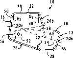
[0009]图1为根据本发明方面提供的示例性的保护针夹的半示意的立体视图;1 is a semi-schematic perspective view of an exemplary protective needle clip provided according to aspects of the present invention;
[0010]图2为图1的保护针夹的半示意的侧视图;Fig. 2 is a semi-schematic side view of the protective needle clip of Fig. 1;
[0011]图3为图1的保护针夹在皮下注射针上处于准备位置的半示意的侧视图;Fig. 3 is a semi-schematic side view of the protective needle clamped on the hypodermic needle of Fig. 1 in a ready position;
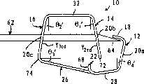
[0012]图4为图1的保护针夹在皮下注射针上处于已激活位置的半示意的侧视图;[0012] FIG. 4 is a semi-schematic side view of the protective needle clip of FIG. 1 in an activated position on a hypodermic needle;
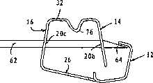
[0013]图5为根据本发明方面提供的可选保护针夹在皮下注射针上处于已激活位置的半示意的侧视图;[0013] FIG. 5 is a semi-schematic side view of an optional protective needle clip on a hypodermic needle in an activated position in accordance with aspects of the present invention;
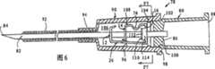
[0014]图6为包括改进的弹簧夹的导管针组件的半示意的横截面侧视图;[0014] FIG. 6 is a semi-schematic cross-sectional side view of a catheter needle assembly including a modified spring clip;
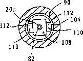
[0015]图7为图6的导管针组件沿直线F7-F7的半示意的端视图;和[0015] FIG. 7 is a semi-schematic end view of the catheter needle assembly of FIG. 6 along line F7-F7; and
[0016]图8为图6的弹簧夹的半示意的立体视图。[0016] FIG. 8 is a semi-schematic perspective view of the spring clip of FIG. 6.
具体实施方式Detailed ways
[0017]连同附图一起在下文进行阐述的详细描述被认为是根据本发明方面提供的目前为止优选保护针夹的实施例,并且不代表本发明可能被构造或利用的唯一形式。本说明书结合图解的实施例阐述了用于构造和使用本发明的保护针夹的特征和步骤。然而应当明白,相同或等效的功能和结构可以由不同的实施例实现,这些实施例也同样包含在本发明的精神和范围之内。此外,如在这里其它地方所表示的,相同的元件标号用于表示相同或类似的元件或部件。[0017] The detailed description set forth below together with the accompanying drawings is believed to provide presently preferred embodiments of protective needle clips according to aspects of the invention and is not representative of the only forms in which the invention may be constructed or utilized. This description sets forth the features and steps for constructing and using the protective needle clip of the present invention with reference to the illustrated embodiments. It should be understood, however, that the same or equivalent functions and structures can be realized by different embodiments, and these embodiments are also included within the spirit and scope of the present invention. Furthermore, as indicated elsewhere herein, the same element numbers are used to refer to the same or similar elements or components.
[0018]图1中显示了根据本发明方面提供的保护针夹的半示意的立体视图,所述保护针夹通常由10表示。在一个示例性的实施例中,保护针夹10(在此“针夹”或“保险夹”)可以为整体结构的针夹,其包括三个针接合臂12、14、16,并且每个臂包括通常为圆形的开口20a、20b、20c。从针夹10的右侧向左侧观察,接合臂可以被称为第一接合臂12,直接从第一接合臂12延伸的第二接合臂16,和直接从第二接合臂延伸的第三接合臂14,即12、16、14。然而,出于下列公开的目的,顺序12、14、16被用于表示第一臂12、第二臂14,和第三臂,并且后面的顺序12、16、14被认为是等效的。第一针接合臂12为最远端的臂,所述臂包括以某一角度从所述臂延伸的指部18和位于所述臂上的第一开口20a。第一接合臂12被构成为保护针尖以防止与其意外接触,如下面进一步讨论的。[0018] FIG. 1 shows a semi-schematic perspective view of a protective needle clip, generally indicated at 10, provided in accordance with aspects of the present invention. In an exemplary embodiment, the protective needle clip 10 (herein "needle clip" or "safety clip") may be a needle clip of unitary construction comprising three
[0019]第三接合臂16直接从第一接合臂12延伸并且在它们之间设置有锚固机构22。在一个示例性的实施例中,锚固机构22包括一个或多个从大致平坦的连接底座26上突出的突出部24。突出部24可以通过将材料粘接、铆接、或焊接到连接底座26上而分别地形成。更为优选地,所述一个或多个突出部24可以通过切割、开槽、或冲压连接底座26的一个或多个部分并且将所述一个或多个带切口部分卷起以形成从连接底座的大致平坦表面上突出的元件而制成。在一个示例性的实施例中,锚固机构22被定位在第一臂12和第三臂16之间并且限定了连接底座26的远端底座部分28和近端底座部分30。在一个示例性的实施例中,远端底座部分28可以从连接底座26的剩余部分以极小的角度或者斜度延伸。[0019] The
[0020]第二接合臂14经连接顶部32从第三接合臂16伸出。第二接合臂14被定位在第一接合臂12和第三接合臂14之间。[0020] The
[0021]在一个示例性的实施例中,针夹10可以通过从诸如不锈钢板的薄平板上冲压针夹和开口20a、20b、20c的轮廓而制成,并随后沿第一折叠部34、第二折叠部36、第三折叠部38、第四折叠部40、第五折叠部42,和第六折叠部44折叠所述冲压材料。折叠的顺序对于所公开的实施例不是至关重要的并且可以根据制造针夹10所涉及的制造要求和设备进行变化。针夹10的大小或尺寸也可以根据其最终用途而进行变化。例如,针夹10可以通过将所述夹子定位在导管毂内部而用于导管组件中,所述导管毂位于具有直针柄的标准皮下注射针上、具有弹簧激活装置的皮下注射针上、Huber针上、安全脊椎穿刺针上、或任何针尖希望被保护的针上。[0021] In an exemplary embodiment, the
[0022]现在参考图2,其显示了图1的保险夹10处于装针前结构的半示意的侧视图,所述装针前结构类似于激活位置(图4)。在装针前结构中,连接顶部32限定了第一平坦表面46。第二针接合臂14和第三针接合臂16均从第一平坦表面46延伸一个不垂直的角度。在一个示例性的实施例中,第二针接合臂14从第二平面48以角度-θ1(负的)延伸,并且第三针接合臂16从第三平面50以角度θ2(正的)延伸,其中第二平面和第三平面都垂直于第一平坦表面46。在可选的示意性实施例中,第二接合臂14可以具有角度θ1(正的)并且第三接合臂16可以具有角度-θ2(负的)。换句话说,第二臂14可以具有角度±θ1并且第三臂16可以具有角度±θ2,其中任何角度的结合都是可接受的,如果整个结构适于保护针尖和将针夹10牢固固定到针上,如下文进一步讨论的。从第四平面52以角度θ3定位连接底座26,并且从第五表面54以角度θ4定位第一接合臂12,所述第五平面通常平行于第二平面48和第三平面50。[0022] Reference is now made to FIG. 2, which shows a semi-schematic side view of the
[0023]在一个示例性实施例的激活位置中,如下文中进一步讨论的,横切第二臂14的第二开口20b的虚线56和横切第三臂14、16的第三开口20c的虚线58彼此相交,与当针夹处于准备位置时通常彼此重合相反。同样地,横切第一臂12的第一开口的虚线60与其他虚线56、58相交,而不是与其他虚线重合。因为接合臂12、14、16在处于装针前结构和激活位置(图4)时以某一角度被定位,所以当从与垂直平面48、50、54相垂直的平面观察时,每个开口20a、20b、20c都包括椭圆形投影。因此,尽管每个开口20a、20b、20c在角度θ1、θ2、θ4大约为0度时具有大致圆形投影,但是它们在角度θ1、θ2、θ4为从0开始的几度(诸如大于±3度左右)时具有大致椭圆形投影。[0023] In the activated position of an exemplary embodiment, as discussed further below, the
[0024]现在参照图3,其显示了处于加载或准备位置的图2的针夹10的半示意的侧视图,所述针夹位于包括针尖64的皮下注射针62上,所述针尖包括无芯(non-coring)针尖(即,诸如Huber针尖)或有芯针尖。在所述加载位置,第二接合臂14被放置成与锚固机构22邻接。在一个示例性的实施例中,这可以通过在第二接合臂14上和在连接底座26上施加作用力以将它们压缩直到第二接合臂14的末端66越过锚固机构22并与锚固机构的作用表面68成抵接关系为止而完成。针夹10可以随后通过将针62穿过大致彼此重合的开口20a、20b、20c保持在准备位置中以将第一针接合臂12保持在偏压位置并随后将剩余的臂14、16及针夹保持在偏压位置。[0024] Referring now to FIG. 3, there is shown a semi-schematic side view of the
[0025]在一个示意性的实施例中,当针夹10处于准备位置时,多个角度θ1、θ2、θ3、θ4大约为0度。然而,对于本领域技术人员来说显而易见的是,所述角度可以通过改变接合臂12、14、16的开口20a、20b、20c和针62的外径之间的相对尺寸而发生几度的变化。例如,如果开口20a、20b、20c的每一个都大于针62的外径,那么所述开口的较大的相对尺寸使开口位于针上时略微椭圆形地投影,并且不会被针物理地阻碍。这样,所述略微椭圆形的投影将允许角度θ1、θ2、θ3、θ4在准备位置时加/减几度。[0025] In an exemplary embodiment, the plurality of angles θ1 , θ2 , θ3 , θ4 are approximately 0 degrees when the
[0026]实际上,在一个示例性的实施例中,开口20a、20b、20c在位于针上的准备位置时具有第一大致椭圆形形状并且在位于针上的激活位置(图4)时具有更大的椭圆形形状。在这种形状下,角度θ1、θ2、θ3、θ4在位于针上的准备位置时都具有整数值。换句话说,开口20a、20b、20c在位于针上时具有大致圆形的形状并且在激活位置时具有椭圆形形状。在这种形状下,角度θ1、θ2、θ3、θ4在处于准备位置时大约为0度并且接合臂12、14、16大致为直的。对于本领域的普通技术人员来说显而易见的是,在任何形状下,开口20a、20b、20c应当充分大于针62的外径以使针尖64从远端位置移动到近端位置,在远端位置处,针尖超过第一接合臂12延伸,在近端位置处,针尖移动靠近第一接合臂12。然而,开口20a、20b、20c还应当限制尺寸从而在针夹处于激活位置时对针62的外表面提供摩擦夹紧。[0026] Indeed, in an exemplary embodiment, the
[0027]现在参考图4,其显示了针夹处于用于保护针尖64的激活位置的半示意的侧视图。当针62从远端位置移动到近端位置时,针夹10从准备位置(图3)转变到激活位置,在所述远端位置处,针尖64超过第一接合臂12延伸(图3),在所述近端位置处,针尖64移动靠近第一接合臂12。由于针62在这两个位置之间移动,针夹10上的偏压被释放并且所述第一接合臂12的至少一部分远离针轴线径向向外移动。在一个示意性的实施例中,第一接合臂12的径向向外的运动被朝针尖64径向移动并抵接针尖的指部18所限定。在一个可选的实施例中,第一接合臂12的径向移动被连接底座26的初始角位置所限定,所述角位置如上所述与角度θ3相关。仍可选地,第一接合臂12可以具有长度或高度使得在激活位置处,指部18保持与针尖64隔开并且指部18和针尖之间的缝隙70比显示的更大。如果指部18抵接针尖64的一部分,由第三接合臂16和连接底座26之间的角位置所限定的角度可以是θ′3,其不同于θ3(图2)。[0027] Reference is now made to FIG. 4, which shows a semi-schematic side view of the needle clip in its activated position for securing the
[0028]在同样的针尖从远端位置向紧靠第一接合臂12的近端位置移动时,针夹10轴向扩张。在一个示例性实施例中,第二接合臂14在第二臂末端66处轴向扩张大约Y2nd*Tanθ′1的距离,这里Y2nd为从与连接顶部32的大致相交的点到第二臂14的大致末端66处的点测得的第二臂14的长度。同样地,第三接合臂16在第三臂末端74处轴向扩张大约Y3rd*Tanθ′2的距离,这里Y3nd为从与连接顶部32大致相交处的点到与连接底座26的大致相交处的点测得的第三臂16的长度。如下文进一步讨论的,由于接合臂14、16保持为偏压状态,角度θ′1和θ′2可以分别不同于θ1和θ2。这使得弹簧夹在激活位置时保持夹紧在针62上。显而易见的是,所述轴向扩张以绝对术语进行描述而不管角度定位。[0028] As the same needle tip moves from a distal position to a proximal position next to the
[0029]仍然参考图4,当针夹10扩张并且第二和第三接合臂14、16如上所述的移动时,位于第二和第三接合臂14、16上的开口20b、20c从大致圆横截面投影为大致椭圆形横截面。可选地,开口20b、20c根据起始角度可以从较小的椭圆形横截面投影为相对较大的椭圆形横截面。在准备位置和激活位置之间转换的过程中,每个开口20b、20c的上和下部分接触针62的外表面并且通过对应于由[θ′1:θ1];[θ′2:θ2]之间的差所限定的偏压或负载的作用力及针夹10的弹力楔靠在外表面上,所述弹力受到所选定的特殊材料及所使用厚度的影响。在一个示意性的实施例中,由开口20b、20c作用在针的外表面上的作用力的数值是如此的使得弹簧夹10保持牢固固定到针上并且针尖64相对于第一接合臂12的进一步向近端的移动受到限制。优选地,这种限制足以承受作用在针62上将针相对于针夹10拔出的正常回缩力。在示意性的实施例中,通过提供相对强硬的弹簧夹诸如通过使用不同材料,通过选择更厚的材料,或通过结合附加的偏压装置可以增加这种限制,如下文进一步讨论的。然而,作用在针上相对于针夹10的有目的的回缩力仍然可以克服开口20b、20c和针外表面之间的摩擦力并且造成针夹10与针62分开。[0029] Still referring to FIG. 4, when the
[0030]现在参考图5,其显示了包括形成在连接顶部32上的盘绕部分76的可选针夹10′。当结合时,盘绕部分76可以增加作用在第二和第三接合臂14、16上的偏压力以增加开口20b、20c的上下部分与针62外表面之间的楔紧力。可选地或除了盘绕部分76之外,可以结合在针中位于针尖64附近的凹口或狭缝以与第二接合臂14的开口20b的边缘发生作用。当结合时,针62中的凹口或狭缝还可以限制或防止针夹10与针分开。[0030] Referring now to FIG. 5, an alternative needle clip 10' including a coiled
[0031]图6为根据本发明方面提供的导管针组件78的半示意的横截面侧视图。在一个示例性实施例中,导管针组件78包括针毂80,所述针毂包括具有针尖84的从针毂的远端86伸出的针82。近端开口88被提供用于通过针腔注射和/或采集流体。[0031] FIG. 6 is a semi-schematic cross-sectional side view of a
[0032]包括从导管毂的远端94伸出的柔性导管92的导管毂90被显示为与针毂80的远端86机械地连接。在一个示例性的实施例中,导管毂90的近端98的内表面96摩擦接合到针毂远端86的外表面100上。肩部或凹口102可以结合在针毂的外表面100上以限制导管毂90在针毂80的外表面上延伸的范围。[0032] A
[0033]位于延伸到导管毂90的内腔106的内表面96上的凸起104可以被提供用于操作定位在内腔106内部的弹簧夹108。凸起104可以包括沿导管毂内表面形成的两个或更多个凸起或连续环。凸起104通过与弹簧夹108上的一个或多个保持翼110发生作用操作弹簧夹108以控制弹簧夹的移动。对于本领域普通技术人员显而易见的是,当针毂80从插入之后的导管毂90上分开时,如下文进一步讨论的,凸起104抵接一个或多个保持翼110以将弹簧夹108和导管毂90保持在一起,并且使弹簧夹相对于针82和针毂80移动。弹簧夹108被凸起104保持并且保持在导管毂90的内腔106中直到针尖84刚好移动到弹簧夹的第一接合臂12的近端为止,因此弹簧夹激活、连接到针82上以保护针尖84,并且从导管毂90中分开。在一个实施例中,凸起104被定位在导管毂90的内腔106中的更远侧,使得当处于所示的准备结构时,凸起104接触一个或多个保持翼110。[0033] A
[0034]在一个示例性的实施例中,用于连接导管针组件78的弹簧夹108除了具有一个或多个保持翼110以外,与参照图1-5显示的弹簧夹基本相同。这样,类似于早些描述的弹簧夹,所示的弹簧夹108包括第一针接合臂12、第二针接合臂14,和第三针接合臂16,并且各接合臂包括开口20a、20b、20c(未显示)。选择地,可以结合卷曲弹簧段76以增加针上的楔紧力,如上面参照图5所讨论的。[0034] In an exemplary embodiment, the
[0035]导管毂组件78可以通过首先在针82上滑动弹簧夹108进行组装。导管毂90的导管92随后在针82上滑动。仅在机械地连接导管毂的内表面96和针毂80的外表面100之前,利用推杆或推棒或类似部件将弹簧夹108通过凸起104推向远侧。可选地,在针毂80的远端部86上形成伸出部使得当导管毂90与针毂80相配合时,伸出部自动地推动弹簧夹108通过凸起104。[0035]
[0036]现在参考图7,其显示了图6的导管针组件78沿直线F7-F7的端视图。如所显示的,针夹108的保持翼110包括第一保持段112和第二保持段114(图6)。第一保持段112被构成为抵接位于导管毂内腔上的凸起104。所述邻接部是如此的使得一个或多个保持翼110的第一保持段112的表面接触凸起104的侧部。所述接触允许弹簧夹108被导管毂90保持并且当导管毂与针毂彼此分开时允许弹簧夹相对于针毂80移动,如下文进一步讨论的。[0036] Referring now to FIG. 7, an end view of the
[0037]现在参考图8,其显示了不具有盘绕部分76的图6和7的弹簧夹108的半示意的立体视图。具体参考一个或多个保持翼110,在一个示例性的实施例中,所述一个或多个保持翼110包括形成在第二保持段114和第三接合臂16之间的第一弹性角116,和形成在第二保持段114和第一保持段112之间的第二弹性角118。第一和第二弹性角116、118可以包括锐角、钝角、或其组合。弹性角116、118允许一个或多个保持翼110围绕由两个角形成的轴线弯曲。所述一个或多个保持翼110的尺寸和厚度应当是这样的使得当凸起104通过作用在针毂上的拉力而施加分离作用力以使针毂从导管毂上分开时,一个或多个保持翼110将发生挠曲、弯曲、或弹性变形。[0037] Referring now to FIG. 8, a semi-schematic perspective view of the
[0038]除了图8之外再次参考图6和7,通过首先相对于导管毂90缩回针毂80可以激活弹簧夹108以阻挡注射器之后的针82的针尖84。这可以通过向近处(向图6的右边)移动针毂来实现。随着针毂80相对于导管毂90向近端移动,凸起104与一个或多个保持翼110发生作用以将弹簧夹108保持在导管毂的内腔106中。随着针毂80持续向近端移动直到针尖84移动到第一接合臂12的近端为止,弹簧夹的连接底座26被释放并且相对于针82径向向外移动。这个移动依次从锚固机构22释放第二接合臂14并且允许第二接合臂14和第三接合臂16轴向扩张。如先前所讨论的,第二接合臂14和第三接合臂的轴向扩张造成位于第二和第三接合臂14、16上的开口20b和20c楔靠在针的外表面上以将弹簧夹固定到针上。[0038] Referring again to FIGS. 6 and 7 in addition to FIG. 8, by first retracting the
[0039]当第二和第三接合臂14、16的开口20b、20c楔靠在针的外表面上时,弹簧夹108如图4所示通过楔紧力保持在针82上。此时,针毂80进一步向近端的移动通过推靠一个或多个保持翼110的第一保持段112的凸起104施加作用在一个或多个保持翼110上的分离作用力。所述分离作用力造成一个或多个保持翼110弯曲或挠曲。因为由开口20b、20c施加在针的外表面上的楔紧力大于弯曲一个或多个保持翼110的作用力,针毂80的向近端移动使一个或多个保持翼110弯曲以充分分开以允许凸起向最近端的移动越过一个或多个保持翼110从而允许导管毂从弹簧夹上分开。[0039] When the
[0040]尽管已经特定地描述了本发明的优选实施例,但是在此阐述的描述和附图不用于限定,并且本领域的普通技术人员应该理解在不脱离本发明范围的情况下,可以对所讨论的实施例进行各种改变,并且所有这些变化和改变都包含在附加的权利要求的范围之内。对针夹的各种变化包括当从准备位置向激活位置转变时,在不脱离本发明精神和范围的情况下可以制造径向扩展部分和至少一个轴向扩张部分。例如,弹簧夹的尺寸可以根据与弹簧夹结合使用的特定皮下注射针组件而改变,材料选择可以改变,角度可以改变,并且弹簧夹可以通过将不同的元件组装或粘接在一起以取代整体结构而制成。其他的变化包括结合不同的锚固机构,诸如通过连接铆钉或沉积材料到连接底座上形成的凸起,提供用于第一臂、第二臂、连接底座等的曲率,以及当激活时,将用于第二和第三臂的偏压结构从径向扩张改成径向压缩或它们的结合。仍有的其他变化包括使用有弹力的弹簧以将针夹朝针尖推动以保护针尖,楔紧在导管毂内部的弹簧夹以通过导管毂朝针尖推动,并且楔紧在Huber针轴环的内部的弹簧夹以通过轴环朝Huber针的针尖推动。于是,本领域的普通技术人员在不脱离本发明精神和范围的情况下可以做出许多改变或变型。[0040] Although the preferred embodiments of the present invention have been specifically described, the description and drawings set forth herein are not intended to be limiting, and those of ordinary skill in the art will understand that, without departing from the scope of the present invention, the Various changes may be made to the discussed embodiments and all such changes and modifications are intended to be included within the scope of the appended claims. Variations on the needle holder include the radially expanding portion and the at least one axially expanding portion when transitioning from the ready position to the activated position without departing from the spirit and scope of the invention. For example, spring clip dimensions can vary depending on the particular hypodermic needle assembly used with the spring clip, material selection can vary, angles can vary, and spring clips can replace monolithic structures by assembling or bonding different elements together And made. Other variations include incorporating different anchoring mechanisms, such as protrusions formed by attaching rivets or depositing material to the attachment base, providing curvature for the first arm, second arm, attachment base, etc., and when activated, will use The biasing configuration for the second and third arms changes from radial expansion to radial compression or a combination thereof. Still other variations include using a resilient spring to push the needle clip toward the needle tip to protect the needle tip, a spring clip wedged inside the catheter hub to push through the catheter hub toward the needle tip, and a spring clip wedged inside the Huber needle collar. The spring clip is pushed through the collar towards the tip of the Huber needle. Accordingly, many changes or modifications may be made by those skilled in the art without departing from the spirit and scope of the invention.
Claims (30)
Translated fromChineseApplications Claiming Priority (2)
| Application Number | Priority Date | Filing Date | Title |
|---|---|---|---|
| US10/677,810US20050075609A1 (en) | 2003-10-01 | 2003-10-01 | Protective needle clips |
| US10/677,810 | 2003-10-01 |
Publications (1)
| Publication Number | Publication Date |
|---|---|
| CN1863565Atrue CN1863565A (en) | 2006-11-15 |
Family
ID=34393811
Family Applications (1)
| Application Number | Title | Priority Date | Filing Date |
|---|---|---|---|
| CNA2004800287082APendingCN1863565A (en) | 2003-10-01 | 2004-08-17 | Protective needle clips |
Country Status (6)
| Country | Link |
|---|---|
| US (1) | US20050075609A1 (en) |
| EP (1) | EP1677860A2 (en) |
| JP (1) | JP2007507288A (en) |
| CN (1) | CN1863565A (en) |
| AU (1) | AU2004283084B2 (en) |
| WO (1) | WO2005039667A2 (en) |
Cited By (10)
| Publication number | Priority date | Publication date | Assignee | Title |
|---|---|---|---|---|
| CN102905754A (en)* | 2010-06-04 | 2013-01-30 | 史密斯医疗Asd公司 | Passive Security Port Device |
| CN104740716A (en)* | 2013-12-27 | 2015-07-01 | 苏州和林精密科技有限公司 | Error pricking and blood stain prevention device of remaining needle |
| CN104918650A (en)* | 2013-01-03 | 2015-09-16 | 威格米德公司 | Spring clip needle guard |
| CN105142707A (en)* | 2012-12-20 | 2015-12-09 | 德尔塔梅德股份公司 | Cannula needle with protective member |
| CN105214178A (en)* | 2011-02-28 | 2016-01-06 | 英杰克蒂姆梅德公司 | Needle guard |
| CN106267521A (en)* | 2016-08-30 | 2017-01-04 | 苏州鱼跃医疗科技有限公司 | Safety device, conduit and introducing needle assembly and remaining needle |
| CN107096092A (en)* | 2011-11-08 | 2017-08-29 | 波利麦迪克有限公司 | Ductus venosus equipment |
| CN107106817A (en)* | 2015-01-02 | 2017-08-29 | 威格米德公司 | Needle hub and IV catheter system including the same |
| CN107771091A (en)* | 2015-06-08 | 2018-03-06 | B.布劳恩梅尔松根股份公司 | Pipe guide and correlation technique with needle guard |
| CN113926024A (en)* | 2016-12-13 | 2022-01-14 | 贝克顿·迪金森公司 | Security device with foldable housing and trigger activation |
Families Citing this family (44)
| Publication number | Priority date | Publication date | Assignee | Title |
|---|---|---|---|---|
| DE20210394U1 (en) | 2002-07-04 | 2002-09-12 | B. Braun Melsungen Ag, 34212 Melsungen | catheter introducer |
| EP1762262A3 (en)* | 2004-02-13 | 2007-03-21 | Smiths Medical ASD, Inc. | Needle tip protector |
| US7651476B2 (en)* | 2004-09-28 | 2010-01-26 | B. Braun Medical Inc. | Protective clips |
| US7850650B2 (en) | 2005-07-11 | 2010-12-14 | Covidien Ag | Needle safety shield with reset |
| US7828773B2 (en) | 2005-07-11 | 2010-11-09 | Covidien Ag | Safety reset key and needle assembly |
| US7905857B2 (en) | 2005-07-11 | 2011-03-15 | Covidien Ag | Needle assembly including obturator with safety reset |
| US20060276747A1 (en) | 2005-06-06 | 2006-12-07 | Sherwood Services Ag | Needle assembly with removable depth stop |
| US7731692B2 (en) | 2005-07-11 | 2010-06-08 | Covidien Ag | Device for shielding a sharp tip of a cannula and method of using the same |
| US8162881B2 (en)* | 2005-08-08 | 2012-04-24 | Smiths Medical Asd, Inc. | Needle guard mechanism with angled strut wall |
| US7632243B2 (en)* | 2005-08-08 | 2009-12-15 | Smiths Medical Asd, Inc. | Duckbill catheter release mechanism |
| US8403886B2 (en) | 2005-08-08 | 2013-03-26 | Smiths Medical Asd, Inc. | Needle guard clip with lip |
| US8251950B2 (en)* | 2005-08-08 | 2012-08-28 | Smiths Medical Asd, Inc. | Needle guard clip with heel |
| US7597681B2 (en)* | 2005-08-08 | 2009-10-06 | Smiths Medical Asd, Inc. | Needle guard mechanism with shroud |
| US7753877B2 (en) | 2005-08-08 | 2010-07-13 | Smiths Medical Asd, Inc. | Needle guard strut wall clip |
| US7654735B2 (en) | 2005-11-03 | 2010-02-02 | Covidien Ag | Electronic thermometer |
| US8382718B2 (en)* | 2006-07-31 | 2013-02-26 | B. Braun Melsungen Ag | Needle assembly and components thereof |
| US8308691B2 (en) | 2006-11-03 | 2012-11-13 | B. Braun Melsungen Ag | Catheter assembly and components thereof |
| JP4994775B2 (en) | 2006-10-12 | 2012-08-08 | 日本コヴィディエン株式会社 | Needle point protector |
| US7744567B2 (en)* | 2006-11-22 | 2010-06-29 | Becton, Dickinson And Company | Reducing withdrawal force in a safety IV catheter |
| US8057431B2 (en)* | 2006-12-21 | 2011-11-15 | B. Braun Melsungen Ag | Hinged cap for needle device |
| US8357104B2 (en) | 2007-11-01 | 2013-01-22 | Coviden Lp | Active stylet safety shield |
| WO2009067646A1 (en)* | 2007-11-21 | 2009-05-28 | Becton, Dickinson And Company | Needle safety device |
| MX2010005610A (en) | 2007-11-21 | 2010-06-01 | Becton Dickinson Co | Safety needle guard. |
| DK2536455T3 (en)* | 2010-02-18 | 2014-06-23 | Sanofi Aventis Deutschland | FINGER PROTECTION FOR AN INJECTION DEVICE |
| RU2729036C2 (en) | 2010-08-05 | 2020-08-03 | Б. Браун Мельзунген Аг | Safe needle device and assembly |
| ES2662356T3 (en) | 2011-04-27 | 2018-04-06 | Kpr U.S., Llc | Safety IV catheter assemblies |
| WO2013048975A1 (en) | 2011-09-26 | 2013-04-04 | Covidien Lp | Safety catheter |
| EP2760521B1 (en) | 2011-09-26 | 2016-01-06 | Covidien LP | Safety iv catheter and needle assembly |
| US8834422B2 (en) | 2011-10-14 | 2014-09-16 | Covidien Lp | Vascular access assembly and safety device |
| ES2666386T3 (en) | 2011-12-07 | 2018-05-04 | Becton, Dickinson And Company | Needle protection sets and infusion devices for use with them |
| SE537334C2 (en)* | 2012-04-27 | 2015-04-07 | Vigmed Ab | Protective device for needle point and mounting device |
| ITMI20121930A1 (en)* | 2012-11-14 | 2014-05-15 | M D L S R L | PROTECTION DEVICE FOR NEEDLES OR CATHETER FOR MEDICAL USE |
| US10357635B2 (en) | 2013-03-12 | 2019-07-23 | Teleflex Medical Incorporated | Catheter insertion device |
| US9717886B2 (en)* | 2013-03-12 | 2017-08-01 | Teleflex Medical Incorporated | Safety clip for a needle |
| US11224724B2 (en) | 2013-03-12 | 2022-01-18 | Teleflex Medical Incorporated | Catheter insertion device |
| US10500376B2 (en) | 2013-06-07 | 2019-12-10 | Becton, Dickinson And Company | IV catheter having external needle shield and internal blood control septum |
| US9555221B2 (en)* | 2014-04-10 | 2017-01-31 | Smiths Medical Asd, Inc. | Constant force hold tip protector for a safety catheter |
| SG11201608547XA (en) | 2014-04-18 | 2016-11-29 | Becton Dickinson Co | Needle capture safety interlock for catheter |
| EP3137147B1 (en)* | 2014-04-28 | 2019-06-19 | Vigmed AB | Catheter instrument and catheter hub therefore |
| US11511052B2 (en) | 2014-11-10 | 2022-11-29 | Becton, Dickinson And Company | Safety IV catheter with V-clip interlock and needle tip capture |
| EP3275484A1 (en)* | 2016-07-26 | 2018-01-31 | Delta Med S.p.A. | Protective element for medical needle assemblies |
| EP4480525A3 (en) | 2017-04-13 | 2025-04-09 | Teleflex Medical Incorporated | Catheter insertion device |
| USD884160S1 (en) | 2019-02-25 | 2020-05-12 | iMed Technology, Inc. | Huber safety needle |
| US12318557B2 (en) | 2020-06-16 | 2025-06-03 | Becton, Dickinson And Company | Catheter system to provide needle safety and related methods |
Family Cites Families (10)
| Publication number | Priority date | Publication date | Assignee | Title |
|---|---|---|---|---|
| US4548658A (en)* | 1985-01-30 | 1985-10-22 | Cook Melvin S | Growth of lattice-graded epilayers |
| US4929241A (en)* | 1988-08-05 | 1990-05-29 | Kulli John C | Medical needle puncture guard |
| ES2081973T3 (en)* | 1989-02-01 | 1996-03-16 | Sero Guard Corp | AUTOMATIC DISPOSABLE HYPODERMIC NEEDLE PROTECTOR. |
| US5053017A (en)* | 1990-02-28 | 1991-10-01 | Chamuel Steven R | Hypodermic needle safety clip |
| US6616630B1 (en)* | 1997-08-20 | 2003-09-09 | B. Braun Melsungen A.G. | Spring clip safety IV catheter |
| US6117108A (en)* | 1997-08-20 | 2000-09-12 | Braun Melsungen Ag | Spring clip safety IV catheter |
| DE29921084U1 (en)* | 1999-12-01 | 2000-02-17 | B. Braun Melsungen Ag, 34212 Melsungen | Short catheter |
| JP3952492B2 (en)* | 2000-06-02 | 2007-08-01 | ニプロ株式会社 | Wing needle clamp |
| EP1344544A4 (en)* | 2000-12-18 | 2008-09-03 | Terumo Corp | Protector and storage needle assembly |
| US6595955B2 (en)* | 2001-03-15 | 2003-07-22 | Specialized Health Products, Inc. | Safety shield for medical needles |
- 2003
- 2003-10-01USUS10/677,810patent/US20050075609A1/ennot_activeAbandoned
- 2004
- 2004-08-17WOPCT/US2004/026602patent/WO2005039667A2/enactiveApplication Filing
- 2004-08-17CNCNA2004800287082Apatent/CN1863565A/enactivePending
- 2004-08-17EPEP04781316Apatent/EP1677860A2/ennot_activeWithdrawn
- 2004-08-17JPJP2006533853Apatent/JP2007507288A/enactivePending
- 2004-08-17AUAU2004283084Apatent/AU2004283084B2/ennot_activeCeased
Cited By (15)
| Publication number | Priority date | Publication date | Assignee | Title |
|---|---|---|---|---|
| CN102905754A (en)* | 2010-06-04 | 2013-01-30 | 史密斯医疗Asd公司 | Passive Security Port Device |
| CN105214178A (en)* | 2011-02-28 | 2016-01-06 | 英杰克蒂姆梅德公司 | Needle guard |
| CN107096092A (en)* | 2011-11-08 | 2017-08-29 | 波利麦迪克有限公司 | Ductus venosus equipment |
| CN105142707A (en)* | 2012-12-20 | 2015-12-09 | 德尔塔梅德股份公司 | Cannula needle with protective member |
| CN104918650B (en)* | 2013-01-03 | 2018-03-09 | 威格米德公司 | spring clip needle shield |
| CN104918650A (en)* | 2013-01-03 | 2015-09-16 | 威格米德公司 | Spring clip needle guard |
| CN104740716B (en)* | 2013-12-27 | 2017-08-01 | 苏州和林微纳科技有限公司 | A kind of anti-error thorn anti-blood polluting device of remaining needle |
| CN104740716A (en)* | 2013-12-27 | 2015-07-01 | 苏州和林精密科技有限公司 | Error pricking and blood stain prevention device of remaining needle |
| CN107106817A (en)* | 2015-01-02 | 2017-08-29 | 威格米德公司 | Needle hub and IV catheter system including the same |
| US11406794B2 (en) | 2015-01-02 | 2022-08-09 | Greiner Bio-One Gmbh | Needle hub and IV catheter system comprising such needle hub |
| CN107771091A (en)* | 2015-06-08 | 2018-03-06 | B.布劳恩梅尔松根股份公司 | Pipe guide and correlation technique with needle guard |
| CN106267521A (en)* | 2016-08-30 | 2017-01-04 | 苏州鱼跃医疗科技有限公司 | Safety device, conduit and introducing needle assembly and remaining needle |
| CN106267521B (en)* | 2016-08-30 | 2023-04-07 | 苏州鱼跃医疗科技有限公司 | Safety device, catheter, introducer needle assembly, and indwelling needle |
| CN113926024A (en)* | 2016-12-13 | 2022-01-14 | 贝克顿·迪金森公司 | Security device with foldable housing and trigger activation |
| CN113926024B (en)* | 2016-12-13 | 2024-04-09 | 贝克顿·迪金森公司 | Safety device with foldable housing and trigger activation |
Also Published As
| Publication number | Publication date |
|---|---|
| JP2007507288A (en) | 2007-03-29 |
| AU2004283084A1 (en) | 2005-05-06 |
| EP1677860A2 (en) | 2006-07-12 |
| AU2004283084B2 (en) | 2008-04-10 |
| US20050075609A1 (en) | 2005-04-07 |
| WO2005039667A2 (en) | 2005-05-06 |
| WO2005039667A3 (en) | 2006-01-12 |
Similar Documents
| Publication | Publication Date | Title |
|---|---|---|
| CN1863565A (en) | Protective needle clips | |
| CA2447944C (en) | Needle shield assembly having hinged needle shield | |
| US10905857B2 (en) | Intravenous catheter apparatus | |
| EP2094335B1 (en) | Hinged cap for needle device | |
| CN112089950B (en) | Needle Safety Devices and Assemblies | |
| US9089673B2 (en) | Locking clip with trigger bushing | |
| EP1951342B1 (en) | Single-handedly actuatable shield for needles | |
| US20170151419A1 (en) | Needle devices with bistable structure and related methods | |
| EP1807135B1 (en) | Protective clips | |
| KR20160147829A (en) | Multi-use blood control safety catheter assembly | |
| CN109922848B (en) | Medication delivery devices for long-term storage | |
| CN114340712A (en) | Hybrid safety spring clip for sharps medical devices and related methods | |
| US12246147B2 (en) | Indwelling needle assembly | |
| HK1093166A (en) | Protective needle clips | |
| JP2004523311A (en) | Devices for medical use with improved safety, especially syringes | |
| TW202017608A (en) | Needle shield remover | |
| RU2812002C2 (en) | Intravenous catheter assembly and method of its production | |
| HK1239576B (en) | Needle safety device and assembly | |
| EP1755714A1 (en) | Improved syringe with retractable needle | |
| HK1248615B (en) | Catheter devices with needle guards and related methods | |
| AU2002311867A1 (en) | Needle shield assembly having hinged needle shield |
Legal Events
| Date | Code | Title | Description |
|---|---|---|---|
| C06 | Publication | ||
| PB01 | Publication | ||
| C10 | Entry into substantive examination | ||
| SE01 | Entry into force of request for substantive examination | ||
| REG | Reference to a national code | Ref country code:HK Ref legal event code:DE Ref document number:1093166 Country of ref document:HK | |
| C12 | Rejection of a patent application after its publication | ||
| RJ01 | Rejection of invention patent application after publication | Open date:20061115 | |
| REG | Reference to a national code | Ref country code:HK Ref legal event code:WD Ref document number:1093166 Country of ref document:HK |