CN1863244B - Method and apparatus for time-domain reflecting measurement of transmission line - Google Patents
Method and apparatus for time-domain reflecting measurement of transmission lineDownload PDFInfo
- Publication number
- CN1863244B CN1863244BCN200510116787.9ACN200510116787ACN1863244BCN 1863244 BCN1863244 BCN 1863244BCN 200510116787 ACN200510116787 ACN 200510116787ACN 1863244 BCN1863244 BCN 1863244B
- Authority
- CN
- China
- Prior art keywords
- signal
- test
- transmission line
- time domain
- test signal
- Prior art date
- Legal status (The legal status is an assumption and is not a legal conclusion. Google has not performed a legal analysis and makes no representation as to the accuracy of the status listed.)
- Expired - Fee Related
Links
Images
Classifications
- G—PHYSICS
- G01—MEASURING; TESTING
- G01R—MEASURING ELECTRIC VARIABLES; MEASURING MAGNETIC VARIABLES
- G01R31/00—Arrangements for testing electric properties; Arrangements for locating electric faults; Arrangements for electrical testing characterised by what is being tested not provided for elsewhere
- G01R31/08—Locating faults in cables, transmission lines, or networks
- G01R31/11—Locating faults in cables, transmission lines, or networks using pulse reflection methods
- H—ELECTRICITY
- H04—ELECTRIC COMMUNICATION TECHNIQUE
- H04M—TELEPHONIC COMMUNICATION
- H04M3/00—Automatic or semi-automatic exchanges
- H04M3/22—Arrangements for supervision, monitoring or testing
- H04M3/26—Arrangements for supervision, monitoring or testing with means for applying test signals or for measuring
- H04M3/28—Automatic routine testing ; Fault testing; Installation testing; Test methods, test equipment or test arrangements therefor
Landscapes
- Physics & Mathematics (AREA)
- General Physics & Mathematics (AREA)
- Engineering & Computer Science (AREA)
- Signal Processing (AREA)
- Monitoring And Testing Of Transmission In General (AREA)
- Testing Of Short-Circuits, Discontinuities, Leakage, Or Incorrect Line Connections (AREA)
- Dc Digital Transmission (AREA)
- Cable Transmission Systems, Equalization Of Radio And Reduction Of Echo (AREA)
Abstract
Translated fromChinese
Description
Translated fromChinese技术领域technical field
本发明涉及通信技术领域,尤其涉及一种传输线路的时域反射测试方法及装置。The invention relates to the field of communication technology, in particular to a time domain reflection test method and device of a transmission line.
背景技术Background technique
xDSL(数据用户线)是一种在电话双绞线(无屏蔽双绞线,UnshieldedTwist Pair,UTP)传输的高速数据传输技术,除了IDSL和SHDSL等基带传输的DSL外,通带传输的xDSL利用频分复用技术使得xDSL与传统电话业务(POTS)共存与同一对双绞线上,其中xDSL占据高频段,POTS占用4KHz一下基带部分,POTS信号与xDSL信号通过分离器分离。xDSL (Data Subscriber Line) is a high-speed data transmission technology transmitted over telephone twisted pair (unshielded twisted pair, Unshielded Twist Pair, UTP). Frequency division multiplexing technology enables xDSL and traditional telephone service (POTS) to coexist on the same pair of twisted pairs, where xDSL occupies the high frequency band, POTS occupies the baseband part below 4KHz, and the POTS signal and xDSL signal are separated by a splitter.
所述的通带传输的xDSL采用离散多音频调制(DMT)。提供多路xDSL接入的系统叫做DSL接入复用器(DSLAM),其系统参考模型如图1所示。The xDSL for passband transmission adopts discrete multi-tone modulation (DMT). The system that provides multiplexDSL access is called DSL access multiplexer (DSLAM), and its system reference model is shown in Figure 1.
众所周知,在开通xDSL业务过程中,通常希望能够获得较高的出线率。为获得较高的出线率就需要保证更多的用户双绞线能够开通xDSL业务。然而,在实际应用环境中,在某一个局点并不是所有的用户双绞线都能正常开通xDSL业务。As we all know, in the process of opening an xDSL service, it is usually hoped to obtain a higher qualifying rate. In order to obtain a higher outgoing line rate, it is necessary to ensure that more twisted-pair lines of users can activate xDSL services. However, in an actual application environment, not all user twisted-pair lines at a certain office can normally enable xDSL services.
对于不能开通xDSL业务的线路就需要进行故障排查、甚至是彻底更换线路以保证能够开通xDSL业务。这一处理过程需要大量的人力、物力,使运营商的运营成本大幅提高。For lines that cannot activate xDSL services, it is necessary to perform troubleshooting, or even completely replace the lines to ensure that xDSL services can be activated. This process requires a lot of manpower and material resources, which greatly increases the operating cost of the operator.
为降低故障排查过程消耗的成本,目前业务采用了SELT(单端线路测试)技术,即通过自动的测试手段对线路进行测试、检查并定位故障。In order to reduce the cost consumed in the troubleshooting process, the current business adopts SELT (Single-Ended Line Test) technology, that is, to test, check and locate faults on the line through automatic testing methods.
目前,市场上的SELT测试设备主要的实现方案是采用TDR(时域反射)、集总参数模型估计方法进行测试进而实现故障定位。At present, the main implementation scheme of SELT test equipment on the market is to use TDR (time domain reflectometry) and lumped parameter model estimation methods for testing and then to realize fault location.
目前,现有TDR测试设备,使用的测试信号一般为方波、正弦波、半波正弦等。当使用这些波形作为测试信号时,存在以下缺点:At present, the existing TDR test equipment generally uses test signals such as square wave, sine wave, and half-wave sine wave. When using these waveforms as test signals, there are the following disadvantages:
(1)由于这些波形的自相关性不强,因而,使得如果回波存在重叠的情况,则接收端无法正确区分。(1) Since the autocorrelation of these waveforms is not strong, if the echoes overlap, the receiving end cannot distinguish them correctly.
(2)当测试环路比较长的时候,回波信号比较弱,使用这些信号容易受到外部信号的干扰,尤其是使用方波的情况。(2) When the test loop is relatively long, the echo signal is relatively weak, and the use of these signals is easily interfered by external signals, especially in the case of using square waves.
(3)使用这些波形进行测试的时候,对于不同的长度的测试环路,测试信号的时长的选择不同。对未知线路的测试要不断的试探性的测试,因而耗时较长。(3) When these waveforms are used for testing, for test loops of different lengths, the duration of the test signal is selected differently. The test to the unknown line requires continuous tentative tests, so it takes a long time.
(4)对于比较复杂的测试环路,比如有两个桥接抽头,选用上述的测试信号有时会无能为力。(4) For a relatively complex test loop, such as two bridge taps, the selection of the above test signal may sometimes be powerless.
(5)当进行线路测试时,有可能对在同一电缆内的正在运行的xDSL线路产生不利的影响。(5) When performing a line test, it may have adverse effects on the running xDSL lines within the same cable.
发明内容Contents of the invention
本发明的目的是提供一种传输线路的时域反射测试方法及装置,从而可以更为方便、准确地对传输线路进行相应的时域反射测试。The purpose of the present invention is to provide a time domain reflection test method and device for a transmission line, so that the corresponding time domain reflection test can be performed on the transmission line more conveniently and accurately.
本发明的目的是通过以下技术方案实现的:The purpose of the present invention is achieved through the following technical solutions:
本发明提供了一种传输线路的时域反射测试方法,包括:The invention provides a time domain reflection test method of a transmission line, comprising:
在传输线路中,根据测试需求确定符合强的自相关性和弱的互相关性要求的测试信号,并发送所述测试信号;In the transmission line, determine a test signal that meets the requirements of strong autocorrelation and weak cross-correlation according to the test requirement, and send the test signal;
接收传输线路中阻抗点反向返回的信号,所述返回的信号为所述测试信号的反射信号与所述测试信号的叠加;Receiving a reversely returned signal from an impedance point in the transmission line, the returned signal is a superposition of the reflected signal of the test signal and the test signal;
对所述返回的信号与所述测试信号进行互相关运算处理,根据互相关运算处理结果获得分开的所述测试信号的分量和所述反射信号的分量,将通过传输线路返回的反射信号识别出来,获得时域反射测试结果。performing cross-correlation processing on the returned signal and the test signal, obtaining separate components of the test signal and components of the reflected signal according to the results of the cross-correlation processing, and identifying the reflected signal returned through the transmission line , to obtain the time domain reflection test results.
所述的测试信号为以下三种信号中的任何一种:The test signal is any one of the following three signals:
随机信号,频率捷变信号,规则调频信号。Random signals, frequency-agile signals, regular FM signals.
所述的随机信号为经过带限的随机信号。The random signal is a band-limited random signal.
本发明提供了一种传输线路的时域反射测试装置,包括:The invention provides a time-domain reflection testing device of a transmission line, comprising:
预定信号发生器:用于生成符合强的自相关性和弱的互相关性要求的测试信号,并输入时域反射测试设备;Predetermined signal generator: used to generate test signals that meet the requirements of strong autocorrelation and weak cross-correlation, and input them into the time domain reflection test equipment;
时域反射测试设备:用于在传输线路中,发送所述预定信号发生器生成的测试信号以及接收传输线路中阻抗点反向返回的信号,所述返回的信号为所述测试信号的反射信号与所述测试信号的叠加;Time domain reflection test equipment: used to send the test signal generated by the predetermined signal generator and receive the reverse return signal of the impedance point in the transmission line in the transmission line, and the returned signal is the reflection signal of the test signal Superposition with said test signal;
互相关运算处理模块:用于根据所述的时域反射测试设备接收到的返回信号,对所述返回的信号与所述测试信号进行互相关运算处理,根据互相关运算处理结果获得分开的所述测试信号的分量和所述反射信号的分量,得到传输线路返回的反射信号,获得时域反射测试结果。Cross-correlation processing module: used to perform cross-correlation processing on the returned signal and the test signal according to the return signal received by the time-domain reflection test equipment, and obtain the separated results according to the cross-correlation processing results The component of the test signal and the component of the reflection signal are obtained to obtain the reflection signal returned by the transmission line, and the time domain reflection test result is obtained.
所述的预定信号发生器包括:The predetermined signal generator includes:
随机信号发生器和带通滤波器,随机信号发生器产生的随机信号经带通滤波器进行带限处理,并输出作为所述的测试信号。A random signal generator and a band-pass filter, the random signal generated by the random signal generator is band-limited processed by the band-pass filter, and output as the test signal.
所述的预定信号发生器包括:The predetermined signal generator includes:
频率发生器和跳频图案控制模块,频率发生器生成设定频率的信号,所述信号在跳频图案控制模块的控制下根据时间信息从信号中选择具体的频率信号,作为测试信号。A frequency generator and a frequency hopping pattern control module, the frequency generator generates a signal with a set frequency, and the signal selects a specific frequency signal from the signals according to time information under the control of the frequency hopping pattern control module as a test signal.
所述的预定信号发生器包括:The predetermined signal generator includes:
调频器,根据作为调频规则模块输出的时间函数进行调频处理获得对应的调频信号,并作为测试信号。The frequency modulator performs frequency modulation processing according to the time function output by the frequency modulation rule module to obtain a corresponding frequency modulation signal, and uses it as a test signal.
所述的互相关运算处理模块设置于时域反射测试设备中,或独立于时域反射测试设备设置。The cross-correlation operation processing module is set in the time domain reflection test equipment, or is set independently from the time domain reflection test equipment.
由上述本发明提供的技术方案可以看出,本发明具有信号能量高、距离分辨率高及抗噪声性能好的优点。因此,按本发明设计的SELT设备具有很强的环境适应性,测试精度高、抗噪声干扰能力强。在各种复杂的环境下能出色的完成测试任务。即采用本发明进行TDR测试,对于大型的DSLAM(数字接入复用器)设备的测试具有非常大的实用价值。It can be seen from the above technical solution provided by the present invention that the present invention has the advantages of high signal energy, high distance resolution and good anti-noise performance. Therefore, the SELT device designed according to the invention has strong environmental adaptability, high test precision and strong anti-noise interference ability. It can complete the test tasks excellently in various complex environments. Namely, adopting the present invention to carry out TDR test has very great practical value for the test of large-scale DSLAM (Digital Access Multiplexer) equipment.
附图说明Description of drawings
图1为xDSL系统的参考模型示意图;Figure 1 is a schematic diagram of a reference model of an xDSL system;
图2为TDR测试模型示意图;Figure 2 is a schematic diagram of the TDR test model;
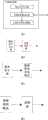
图3为本发明所述装置的结构示意图;Fig. 3 is the structural representation of device described in the present invention;
图4为所述预定信号发生器的结构图一;Fig. 4 is a structural diagram 1 of the predetermined signal generator;
图5为所述预定信号发生器的结构图二;Fig. 5 is the second structural diagram of the predetermined signal generator;
图6为所述预定信号发生器的结构图三;Fig. 6 is a structural diagram three of the predetermined signal generator;
图7为伪随机信号的示意图;7 is a schematic diagram of a pseudorandom signal;
图8为伪随机信号的自相关结果示意图;Fig. 8 is a schematic diagram of the autocorrelation result of the pseudorandom signal;
图9为经时延后与原信号产生时域混叠的伪随机叠加信号示意图;Fig. 9 is a schematic diagram of a pseudo-randomly superimposed signal that is time-domain aliased with the original signal after time delay;
图10为伪随机叠加信号与原信号的互相关运算结果示意图;Fig. 10 is a schematic diagram of the cross-correlation operation result of the pseudo-randomly superimposed signal and the original signal;
图11为桥接抽头的线路模型示意图。Figure 11 is a schematic diagram of a line model of a bridged tap.
具体实施方式Detailed ways
本发明主要是在TDR测试过程中,选用一组具有较强的自相关性及与其他信号间具有较弱互相关性的测试信号,从而可以利用测试信号本身的较强的自相关性的特征来解决现有技术中存在的缺点,提高测试的准确度。The present invention mainly selects a group of test signals with strong autocorrelation and weak cross-correlation with other signals during the TDR test process, so that the strong autocorrelation feature of the test signal itself can be used To solve the shortcomings existing in the prior art, improve the accuracy of the test.
为对本发明有进一步了解,下面首先对TDR测试的过程进行说明。In order to have a further understanding of the present invention, the process of the TDR test will be described first below.
如图2所示,TDR的测试由发送器1把经驱动后的测试信号经二四线转换3后驱动到线路5上。信号沿着方向6前进,当遇到阻抗变换点8的时候,信号会发生反射现象向相反的方向7前进,最终通过3到达接收器2,在返回的信号中反射信号将与原发送信号方向6的信号叠加。TDR测试便是对返回到接收器2的信号进行处理获得相应的测试结果,以定位故障点等。As shown in Figure 2, the test of TDR is driven by the transmitter 1 to the line 5 after the driven test signal is converted 3 to two or four lines. The signal advances along the direction 6. When encountering the impedance transformation point 8, the signal will reflect and advance in the opposite direction 7, and finally reach the receiver 2 through 3. In the returned signal, the reflected signal will be in the same direction as the original sent signal 6 signals superimposed. The TDR test is to process the signal returned to the receiver 2 to obtain corresponding test results, so as to locate fault points and the like.
图2所示的信号处理11部分承担发送测试信号的任务,以及分析接收信号并给出测试结果的工作。The signal processing part 11 shown in Fig. 2 undertakes the task of sending the test signal, as well as the work of analyzing the received signal and giving the test result.
下面将对本发明所述的方法的实现过程进行说明。The implementation process of the method described in the present invention will be described below.
本发明是为了实现对图2中接收器接收到的返回的信号进行测试,为此,本发明通过分析提出采用非常适合用于SELT的测试信号的一组带限测试信号,这种测试信号的主要特征是具有强自相关性同时与其他信号又具有比较弱的互相关性。The present invention is in order to realize that the signal that the receiver in Fig. 2 receives returns is tested, for this reason, the present invention proposes to adopt a group of band-limited test signal that is very suitable for the test signal of SELT by analysis, the test signal of this test signal The main feature is that it has strong autocorrelation and relatively weak cross-correlation with other signals.
本发明中,参照图2所示,具体的TDR测试处理过程包括:In the present invention, with reference to shown in Fig. 2, concrete TDR test process comprises:
首先,通过发送器1发送所述的非常适合用于SELT的测试信号的一组带限测试信号,所述的信号将被通过传输线路进行传输,当经过阻抗变换点8时,将会经方向7返回,并被接收器2接收;First, a group of band-limited test signals that are very suitable for SELT test signals are sent through the transmitter 1, and the signals will be transmitted through the transmission line. When passing through the impedance transformation point 8, they will pass through the direction 7 returns and is received by receiver 2;
其次,对接收器2接收到的信号进行互相关运算处理,具体为将接收到的信号与发送器1原发送的信号进行互相关运算处理,从而将经阻抗变换点8时反射的信号识别出来,进而获得相应的TDR测试结果。Secondly, perform cross-correlation processing on the signal received by the receiver 2, specifically, perform cross-correlation processing on the received signal and the original signal sent by the transmitter 1, so as to identify the signal reflected at the impedance transformation point 8 , and then obtain the corresponding TDR test results.
可以看出,本发明主要是采用了相应具有较强的自相关性及较弱的互相关性的测试信号进行TDR测试,才使得本发明能够具有较佳的测试效果,因此,下面将对本发明可以采用的几种测试信号进行说明。It can be seen that the present invention mainly adopts corresponding test signals with stronger autocorrelation and weaker cross-correlation to carry out TDR test, so that the present invention can have better test results. Therefore, the present invention will be described below Several test signals that can be used are illustrated.
(1)经过带限的随机信号(1) Band-limited random signal
所述的随机信号也包括但不限于由一些序列发生器产生的伪随机信号,为保证测试的使用还需要对所述伪随机信号进行带通滤波处理,并将处理后的信号作为测试信号。The random signal also includes but not limited to the pseudo-random signal generated by some sequence generators. In order to ensure the use of the test, the pseudo-random signal needs to be band-pass filtered, and the processed signal is used as the test signal.
(2)频率捷变信号(2) Frequency agile signal
所谓频率捷变信号可以在不同的时间片上取不同的频率;在设计频率捷变信号前先确定使用那些频率,然后,由频率发生器产生相应频率的信号,并由跳频图案决定在哪个时间片上采用哪个频率,从而获得测试用的频率捷变信号;所述的调频图案可以是周期性固定的,也可以是随机产生的。The so-called frequency agility signal can take different frequencies on different time slices; before designing the frequency agility signal, determine which frequencies to use, and then, the frequency generator generates the signal of the corresponding frequency, and the frequency hopping pattern determines at which time Which frequency is used on the chip, so as to obtain the frequency agility signal for testing; the frequency modulation pattern can be fixed periodically or randomly generated.
(3)规则调频信号(3) Regular FM signal
规则调频信号
本发明还提供了一种传输线路的时域反射测试装置,如图3所示,具体包括以下三个组成部分:The present invention also provides a time domain reflection testing device for a transmission line, as shown in Figure 3, which specifically includes the following three components:
(1)预定信号发生器(1) Scheduled signal generator
用于生成符合自相关性和互相关性要求的测试信号,并输入时域反射测试设备,而且,所述的预定信号发生器分别可以为以下三种结构之一:It is used to generate a test signal that meets the requirements of autocorrelation and cross-correlation, and input it into the time domain reflection test equipment, and the predetermined signal generator can be one of the following three structures:
如图4所示,包括随机信号发生器和带通滤波器,随机信号发生器产生的随机信号经带通滤波器进行带限处理,并输出作为所述的测试信号;As shown in Fig. 4, comprise random signal generator and band-pass filter, the random signal that random signal generator produces carries out band-limiting processing through band-pass filter, and output as described test signal;
或者,or,
如图5所示,包括频率发生器和跳频图案控制模块,频率发生器生成设定频率的信号,所述信号在跳频图案控制模块的控制下根据时间信息从信号中选择具体的频率信号,作为测试信号;As shown in Figure 5, it includes a frequency generator and a frequency hopping pattern control module, the frequency generator generates a signal with a set frequency, and the signal selects a specific frequency signal from the signal according to time information under the control of the frequency hopping pattern control module , as a test signal;
或者,or,
如图6所示,包括调频器,用于根据作为调频规则模块输出的的时间函数进行调频处理获得对应的调频信号,并作为测试信号。As shown in FIG. 6 , a frequency modulator is included for performing frequency modulation processing according to the time function output by the frequency modulation rule module to obtain a corresponding frequency modulation signal as a test signal.
(2)时域反射测试设备,即TDR测试设备:用于根据所述预定信号发生器生成的测试信号进行时域反射测试,该测试设备为现有的设备;(2) Time domain reflection test equipment, namely TDR test equipment: used for performing time domain reflection test according to the test signal generated by the predetermined signal generator, the test equipment is existing equipment;
(3)互相关运算处理模块:根据所述的时域反射测试设备接收到的经过叠加的反射信号,并对其与上述的测试信号进行互相关运算处理,获得时域反射测试结果,即从返回的信号中识别出相应的反射信号,该模块可以设置于TDR测试设备中,或者独立于TDR测试设备设置。(3) Cross-correlation operation processing module: according to the superimposed reflection signal received by the time-domain reflection test equipment, and carry out cross-correlation operation processing with the above-mentioned test signal to obtain the time-domain reflection test result, that is, from The corresponding reflected signal is identified in the returned signal, and the module can be set in the TDR test equipment, or set independently of the TDR test equipment.
为对本发明有进一步的理解,下面将结合附图以通过带限伪随机信号(x(n))实现TDR测试为例说明本发明的具体实现方式,并阐述使用本发明规定的具有较强的自相关性及较弱的互相关性的测试信号带来优点的原理。对于其他测试信号相应的处理过程具有类似的特性因此不一一说明。For having further understanding to the present invention, below in conjunction with accompanying drawing, realize the TDR test by band-limited pseudo-random signal (x(n)) as an example to illustrate the specific implementation of the present invention, and set forth the use of the provisions of the present invention with stronger The principle that autocorrelation and weaker cross-correlation test signals bring advantages. Corresponding processing procedures for other test signals have similar characteristics and thus will not be described one by one.
本发明中,采用具有很强的自相关性带限伪随机信号(x(n)n=1...N)作为测试信号,图7为带限伪随机的时域波形。In the present invention, a band-limited pseudo-random signal (x(n)n=1...N) with strong autocorrelation is used as the test signal, and FIG. 7 is a time-domain waveform of the band-limited pseudo-random signal.
采用自相关运算用公式:
当发送所述的伪随机信号后,在TDR的接收器将接收到返回的信号,如图9所示,返回的信号是两个相同的带限伪随机信号经过不同的时延后叠加的时域波形y(n),y(n)=a·x(n)+b·x(n-k)k<N,a、b分别为与频率有关的泄漏、反射系数。对于接收到的信号仅仅从时域上判断是无法将这两个不同时延的信号分开,即无法获得反射信号的信息。这是因为信号在时间上发生了混叠。为区分出反射信号,则需要将x(n)和y(n)做一个互相关操作结果,相应的互相关运算操作结果如图10所示,从放大部分可以看出y(n)的两个分量x(n)和x(n-k)被分开了。其中圈1为x(n),即泄漏的原始波形,圈2为x(n-k),即反射波形。After sending the pseudo-random signal, the receiver at TDR will receive the returned signal, as shown in Figure 9, the returned signal is the superposition of two identical band-limited pseudo-random signals after different time delays Domain waveform y(n), y(n)=a·x(n)+b·x(n-k)k<N, a and b are frequency-related leakage and reflection coefficients, respectively. Judging the received signal only from the time domain, it is impossible to separate the two signals with different time delays, that is, it is impossible to obtain the information of the reflected signal. This is because the signal is aliased in time. In order to distinguish the reflected signal, it is necessary to perform a cross-correlation operation result on x(n) and y(n). The corresponding cross-correlation operation result is shown in Figure 10. From the enlarged part, it can be seen that the two components x(n) and x(n-k) are separated. Among them, circle 1 is x(n), that is, the original waveform of leakage, and circle 2 is x(n-k), that is, the reflected waveform.
本发明中,所述的带限伪随机信号与SELT测试环境中的其他信号,主要是一些具有某些特性的噪声信号(n(n))的互相关性很小,如线路噪声、脉冲噪声、串扰噪声等;用公式表示即:结果趋近于0,因此,带限伪随机信号与SELT测试环境中的其他信号的互相关性很小。In the present invention, the cross-correlation between the band-limited pseudo-random signal and other signals in the SELT test environment, mainly some noise signals (n(n)) with certain characteristics is very small, such as line noise, impulse noise , crosstalk noise, etc.; expressed in formulas: The result is close to 0, therefore, the band-limited pseudo-random signal has little cross-correlation with other signals in the SELT test environment.
下面将再结合附图对本发明存在的优点进行分析说明。The advantages of the present invention will be analyzed and described below in conjunction with the accompanying drawings.
本发明主要包括以下三方面的优点:The present invention mainly comprises the advantage of following three aspects:
(一)信号能量高:(1) High signal energy:
如图2所示,从阻抗变换点8反射的回波7要能被正确接收,便要求回波7的能量越高越好。如果要信号能量高,可以增加信号幅度亦可以增加信号的时长。显然在SELT系统不可能无限制的增加信号的幅度;实际上由于减小干扰等各种因素应该使用增加时长的办法增加能量。而使用现有技术提供的方波、正弦波等测试信号,由于要抗反射波的时域混叠也不可能发射很长时间的测试信号,一般在1km的测试环路上要保证距离测试精度在50米的前提下,最大的测试信号的时长约为0.5uS左右。但是如果使用本发明提供的三种测试信号则信号就可以使用时长十几微妙甚至更长的测试信号。As shown in FIG. 2 , if the echo 7 reflected from the impedance transformation point 8 can be received correctly, the higher the energy of the echo 7 is required, the better. If you want high signal energy, you can increase the signal amplitude or increase the duration of the signal. Obviously, it is impossible to increase the amplitude of the signal without limit in the SELT system; in fact, due to various factors such as reducing interference, the method of increasing the duration should be used to increase the energy. However, using the square wave, sine wave and other test signals provided by the existing technology, it is impossible to transmit the test signal for a long time due to the time domain aliasing of the anti-reflection wave. Generally, the distance test accuracy must be ensured on the 1km test loop. Under the premise of 50 meters, the duration of the largest test signal is about 0.5uS. However, if the three test signals provided by the present invention are used, the signal can use a test signal with a duration of more than ten microseconds or even longer.
(二)距离分辨率高:(2) High distance resolution:
当测试线路上存在两个连续的阻抗变换点,这两个阻抗变换点的距离比较近,如图11所示。线路总长3000米,在2000米的位置有一个30米桥接抽头12。此时,如果采用现有技术提供的方波、正弦波等测试信号,如果要正确测试桥接抽头12的话测试信号的时长必须小于0.5uS。但是这么小能量的信号从点13、点14反射回点1的时候衰减很大,根本无法接收。但是如果使用本发明提供的三种测试信号,如带限伪随机信号,则返回到点1的信号虽然幅度很小,但由于持续时间比较长,仍然具有比较大的能量可以被正确接收。然后在根据带限伪随机信号的时间压缩特性便能正确的分辨点13和14点的回波时间点。When there are two continuous impedance transformation points on the test line, the distance between these two impedance transformation points is relatively close, as shown in FIG. 11 . The total length of the line is 3000 meters, and there is a 30-meter bridge tap 12 at the position of 2000 meters. At this time, if the test signals such as square wave and sine wave provided by the prior art are used, the duration of the test signal must be less than 0.5uS if the bridge tap 12 is to be tested correctly. However, when the signal with such a small energy is reflected from point 13 and point 14 back to point 1, the attenuation is very large, and it cannot be received at all. However, if the three test signals provided by the present invention are used, such as the band-limited pseudo-random signal, although the amplitude of the signal returned to point 1 is small, it still has relatively large energy and can be correctly received due to its relatively long duration. Then, according to the time compression characteristic of the band-limited pseudo-random signal, the echo time points at points 13 and 14 can be correctly distinguished.
(3)抗噪声性能好:(3) Good anti-noise performance:
当接收到的信号信噪比小于0,也即被噪声淹没的时候,由于带限伪随机信号于噪声的互相关性非常小,因此,从接收信号中能够很好的提取出回波信号。但如果使用现有技术提供的方波、正弦波等测试信号,则必须要求信噪比大于0,回波信号才有可能被正确检测。When the signal-to-noise ratio of the received signal is less than 0, that is, when it is submerged by noise, since the cross-correlation between the band-limited pseudo-random signal and the noise is very small, the echo signal can be well extracted from the received signal. However, if the test signals such as square wave and sine wave provided by the prior art are used, the signal-to-noise ratio must be greater than 0, so that the echo signal can be detected correctly.
由于本发明存在以上主要优点,因此,按本发明设计的SELT设备具有很强的环境适应性,测试精度高、抗噪声干扰能力强。在各种复杂的环境下能出色的完成测试任务。也就是说,使用所述的伪随机信号、频率捷变信号和规则调频信号作为测试信号进行TDR测试对于大型的DSLAM设备的测试具有非常大的使用价值。Due to the above main advantages of the present invention, the SELT device designed according to the present invention has strong environmental adaptability, high test accuracy and strong anti-noise interference ability. It can complete the test tasks excellently in various complex environments. That is to say, using the pseudo-random signal, frequency-agile signal and regular FM signal as the test signal to perform the TDR test is very valuable for testing large-scale DSLAM equipment.
以上所述,仅为本发明较佳的具体实施方式,但本发明的保护范围并不局限于此,任何熟悉本技术领域的技术人员在本发明揭露的技术范围内,可轻易想到的变化或替换,都应涵盖在本发明的保护范围之内。因此,本发明的保护范围应该以权利要求的保护范围为准。The above is only a preferred embodiment of the present invention, but the scope of protection of the present invention is not limited thereto. Any person skilled in the art within the technical scope disclosed in the present invention can easily think of changes or Replacement should be covered within the protection scope of the present invention. Therefore, the protection scope of the present invention should be determined by the protection scope of the claims.
Claims (8)
Priority Applications (4)
| Application Number | Priority Date | Filing Date | Title |
|---|---|---|---|
| CN200510116787.9ACN1863244B (en) | 2005-10-28 | 2005-10-28 | Method and apparatus for time-domain reflecting measurement of transmission line |
| US11/588,106US7532011B2 (en) | 2005-10-28 | 2006-10-26 | Method and apparatus for time domain reflection test of transmission line |
| FI20060952AFI20060952A7 (en) | 2005-10-28 | 2006-10-27 | Method and apparatus for transmission line time domain reflection test |
| FR0609504AFR2892824A1 (en) | 2005-10-28 | 2006-10-30 | Method and apparatus for time-domain reflecting measurement of transmission line |
Applications Claiming Priority (1)
| Application Number | Priority Date | Filing Date | Title |
|---|---|---|---|
| CN200510116787.9ACN1863244B (en) | 2005-10-28 | 2005-10-28 | Method and apparatus for time-domain reflecting measurement of transmission line |
Publications (2)
| Publication Number | Publication Date |
|---|---|
| CN1863244A CN1863244A (en) | 2006-11-15 |
| CN1863244Btrue CN1863244B (en) | 2013-10-02 |
Family
ID=37232216
Family Applications (1)
| Application Number | Title | Priority Date | Filing Date |
|---|---|---|---|
| CN200510116787.9AExpired - Fee RelatedCN1863244B (en) | 2005-10-28 | 2005-10-28 | Method and apparatus for time-domain reflecting measurement of transmission line |
Country Status (4)
| Country | Link |
|---|---|
| US (1) | US7532011B2 (en) |
| CN (1) | CN1863244B (en) |
| FI (1) | FI20060952A7 (en) |
| FR (1) | FR2892824A1 (en) |
Cited By (134)
| Publication number | Priority date | Publication date | Assignee | Title |
|---|---|---|---|---|
| US9640850B2 (en) | 2015-06-25 | 2017-05-02 | At&T Intellectual Property I, L.P. | Methods and apparatus for inducing a non-fundamental wave mode on a transmission medium |
| US9667317B2 (en) | 2015-06-15 | 2017-05-30 | At&T Intellectual Property I, L.P. | Method and apparatus for providing security using network traffic adjustments |
| US9674711B2 (en) | 2013-11-06 | 2017-06-06 | At&T Intellectual Property I, L.P. | Surface-wave communications and methods thereof |
| US9685992B2 (en) | 2014-10-03 | 2017-06-20 | At&T Intellectual Property I, L.P. | Circuit panel network and methods thereof |
| US9705610B2 (en) | 2014-10-21 | 2017-07-11 | At&T Intellectual Property I, L.P. | Transmission device with impairment compensation and methods for use therewith |
| US9705561B2 (en) | 2015-04-24 | 2017-07-11 | At&T Intellectual Property I, L.P. | Directional coupling device and methods for use therewith |
| US9722318B2 (en) | 2015-07-14 | 2017-08-01 | At&T Intellectual Property I, L.P. | Method and apparatus for coupling an antenna to a device |
| US9729197B2 (en) | 2015-10-01 | 2017-08-08 | At&T Intellectual Property I, L.P. | Method and apparatus for communicating network management traffic over a network |
| US9735833B2 (en) | 2015-07-31 | 2017-08-15 | At&T Intellectual Property I, L.P. | Method and apparatus for communications management in a neighborhood network |
| US9742462B2 (en) | 2014-12-04 | 2017-08-22 | At&T Intellectual Property I, L.P. | Transmission medium and communication interfaces and methods for use therewith |
| US9742521B2 (en) | 2014-11-20 | 2017-08-22 | At&T Intellectual Property I, L.P. | Transmission device with mode division multiplexing and methods for use therewith |
| US9749013B2 (en) | 2015-03-17 | 2017-08-29 | At&T Intellectual Property I, L.P. | Method and apparatus for reducing attenuation of electromagnetic waves guided by a transmission medium |
| US9748626B2 (en) | 2015-05-14 | 2017-08-29 | At&T Intellectual Property I, L.P. | Plurality of cables having different cross-sectional shapes which are bundled together to form a transmission medium |
| US9749053B2 (en) | 2015-07-23 | 2017-08-29 | At&T Intellectual Property I, L.P. | Node device, repeater and methods for use therewith |
| US9762289B2 (en) | 2014-10-14 | 2017-09-12 | At&T Intellectual Property I, L.P. | Method and apparatus for transmitting or receiving signals in a transportation system |
| US9769128B2 (en) | 2015-09-28 | 2017-09-19 | At&T Intellectual Property I, L.P. | Method and apparatus for encryption of communications over a network |
| US9769020B2 (en) | 2014-10-21 | 2017-09-19 | At&T Intellectual Property I, L.P. | Method and apparatus for responding to events affecting communications in a communication network |
| US9768833B2 (en) | 2014-09-15 | 2017-09-19 | At&T Intellectual Property I, L.P. | Method and apparatus for sensing a condition in a transmission medium of electromagnetic waves |
| US9780834B2 (en) | 2014-10-21 | 2017-10-03 | At&T Intellectual Property I, L.P. | Method and apparatus for transmitting electromagnetic waves |
| US9787412B2 (en) | 2015-06-25 | 2017-10-10 | At&T Intellectual Property I, L.P. | Methods and apparatus for inducing a fundamental wave mode on a transmission medium |
| US9788326B2 (en) | 2012-12-05 | 2017-10-10 | At&T Intellectual Property I, L.P. | Backhaul link for distributed antenna system |
| US9793951B2 (en) | 2015-07-15 | 2017-10-17 | At&T Intellectual Property I, L.P. | Method and apparatus for launching a wave mode that mitigates interference |
| US9793955B2 (en) | 2015-04-24 | 2017-10-17 | At&T Intellectual Property I, Lp | Passive electrical coupling device and methods for use therewith |
| US9793954B2 (en) | 2015-04-28 | 2017-10-17 | At&T Intellectual Property I, L.P. | Magnetic coupling device and methods for use therewith |
| US9800327B2 (en) | 2014-11-20 | 2017-10-24 | At&T Intellectual Property I, L.P. | Apparatus for controlling operations of a communication device and methods thereof |
| US9820146B2 (en) | 2015-06-12 | 2017-11-14 | At&T Intellectual Property I, L.P. | Method and apparatus for authentication and identity management of communicating devices |
| US9838078B2 (en) | 2015-07-31 | 2017-12-05 | At&T Intellectual Property I, L.P. | Method and apparatus for exchanging communication signals |
| US9838896B1 (en) | 2016-12-09 | 2017-12-05 | At&T Intellectual Property I, L.P. | Method and apparatus for assessing network coverage |
| US9847566B2 (en) | 2015-07-14 | 2017-12-19 | At&T Intellectual Property I, L.P. | Method and apparatus for adjusting a field of a signal to mitigate interference |
| US9847850B2 (en) | 2014-10-14 | 2017-12-19 | At&T Intellectual Property I, L.P. | Method and apparatus for adjusting a mode of communication in a communication network |
| US9853342B2 (en) | 2015-07-14 | 2017-12-26 | At&T Intellectual Property I, L.P. | Dielectric transmission medium connector and methods for use therewith |
| US9860075B1 (en) | 2016-08-26 | 2018-01-02 | At&T Intellectual Property I, L.P. | Method and communication node for broadband distribution |
| US9866276B2 (en) | 2014-10-10 | 2018-01-09 | At&T Intellectual Property I, L.P. | Method and apparatus for arranging communication sessions in a communication system |
| US9866309B2 (en) | 2015-06-03 | 2018-01-09 | At&T Intellectual Property I, Lp | Host node device and methods for use therewith |
| US9865911B2 (en) | 2015-06-25 | 2018-01-09 | At&T Intellectual Property I, L.P. | Waveguide system for slot radiating first electromagnetic waves that are combined into a non-fundamental wave mode second electromagnetic wave on a transmission medium |
| US9871283B2 (en) | 2015-07-23 | 2018-01-16 | At&T Intellectual Property I, Lp | Transmission medium having a dielectric core comprised of plural members connected by a ball and socket configuration |
| US9871282B2 (en) | 2015-05-14 | 2018-01-16 | At&T Intellectual Property I, L.P. | At least one transmission medium having a dielectric surface that is covered at least in part by a second dielectric |
| US9871558B2 (en) | 2014-10-21 | 2018-01-16 | At&T Intellectual Property I, L.P. | Guided-wave transmission device and methods for use therewith |
| US9876571B2 (en) | 2015-02-20 | 2018-01-23 | At&T Intellectual Property I, Lp | Guided-wave transmission device with non-fundamental mode propagation and methods for use therewith |
| US9876264B2 (en) | 2015-10-02 | 2018-01-23 | At&T Intellectual Property I, Lp | Communication system, guided wave switch and methods for use therewith |
| US9876605B1 (en) | 2016-10-21 | 2018-01-23 | At&T Intellectual Property I, L.P. | Launcher and coupling system to support desired guided wave mode |
| US9882257B2 (en) | 2015-07-14 | 2018-01-30 | At&T Intellectual Property I, L.P. | Method and apparatus for launching a wave mode that mitigates interference |
| US9887447B2 (en) | 2015-05-14 | 2018-02-06 | At&T Intellectual Property I, L.P. | Transmission medium having multiple cores and methods for use therewith |
| US9893795B1 (en) | 2016-12-07 | 2018-02-13 | At&T Intellectual Property I, Lp | Method and repeater for broadband distribution |
| US9906269B2 (en) | 2014-09-17 | 2018-02-27 | At&T Intellectual Property I, L.P. | Monitoring and mitigating conditions in a communication network |
| US9904535B2 (en) | 2015-09-14 | 2018-02-27 | At&T Intellectual Property I, L.P. | Method and apparatus for distributing software |
| US9912033B2 (en) | 2014-10-21 | 2018-03-06 | At&T Intellectual Property I, Lp | Guided wave coupler, coupling module and methods for use therewith |
| US9912382B2 (en) | 2015-06-03 | 2018-03-06 | At&T Intellectual Property I, Lp | Network termination and methods for use therewith |
| US9912027B2 (en) | 2015-07-23 | 2018-03-06 | At&T Intellectual Property I, L.P. | Method and apparatus for exchanging communication signals |
| US9912419B1 (en) | 2016-08-24 | 2018-03-06 | At&T Intellectual Property I, L.P. | Method and apparatus for managing a fault in a distributed antenna system |
| US9913139B2 (en) | 2015-06-09 | 2018-03-06 | At&T Intellectual Property I, L.P. | Signal fingerprinting for authentication of communicating devices |
| US9911020B1 (en) | 2016-12-08 | 2018-03-06 | At&T Intellectual Property I, L.P. | Method and apparatus for tracking via a radio frequency identification device |
| US9917341B2 (en) | 2015-05-27 | 2018-03-13 | At&T Intellectual Property I, L.P. | Apparatus and method for launching electromagnetic waves and for modifying radial dimensions of the propagating electromagnetic waves |
| US9929755B2 (en) | 2015-07-14 | 2018-03-27 | At&T Intellectual Property I, L.P. | Method and apparatus for coupling an antenna to a device |
| US9927517B1 (en) | 2016-12-06 | 2018-03-27 | At&T Intellectual Property I, L.P. | Apparatus and methods for sensing rainfall |
| US9930668B2 (en) | 2013-05-31 | 2018-03-27 | At&T Intellectual Property I, L.P. | Remote distributed antenna system |
| US9948355B2 (en) | 2014-10-21 | 2018-04-17 | At&T Intellectual Property I, L.P. | Apparatus for providing communication services and methods thereof |
| US9948333B2 (en) | 2015-07-23 | 2018-04-17 | At&T Intellectual Property I, L.P. | Method and apparatus for wireless communications to mitigate interference |
| US9948354B2 (en) | 2015-04-28 | 2018-04-17 | At&T Intellectual Property I, L.P. | Magnetic coupling device with reflective plate and methods for use therewith |
| US9954287B2 (en) | 2014-11-20 | 2018-04-24 | At&T Intellectual Property I, L.P. | Apparatus for converting wireless signals and electromagnetic waves and methods thereof |
| US9954286B2 (en) | 2014-10-21 | 2018-04-24 | At&T Intellectual Property I, L.P. | Guided-wave transmission device with non-fundamental mode propagation and methods for use therewith |
| US9967173B2 (en) | 2015-07-31 | 2018-05-08 | At&T Intellectual Property I, L.P. | Method and apparatus for authentication and identity management of communicating devices |
| US9973416B2 (en) | 2014-10-02 | 2018-05-15 | At&T Intellectual Property I, L.P. | Method and apparatus that provides fault tolerance in a communication network |
| US9973940B1 (en) | 2017-02-27 | 2018-05-15 | At&T Intellectual Property I, L.P. | Apparatus and methods for dynamic impedance matching of a guided wave launcher |
| US9991580B2 (en) | 2016-10-21 | 2018-06-05 | At&T Intellectual Property I, L.P. | Launcher and coupling system for guided wave mode cancellation |
| US9999038B2 (en) | 2013-05-31 | 2018-06-12 | At&T Intellectual Property I, L.P. | Remote distributed antenna system |
| US9998870B1 (en) | 2016-12-08 | 2018-06-12 | At&T Intellectual Property I, L.P. | Method and apparatus for proximity sensing |
| US9997819B2 (en) | 2015-06-09 | 2018-06-12 | At&T Intellectual Property I, L.P. | Transmission medium and method for facilitating propagation of electromagnetic waves via a core |
| US10009067B2 (en) | 2014-12-04 | 2018-06-26 | At&T Intellectual Property I, L.P. | Method and apparatus for configuring a communication interface |
| US10020844B2 (en) | 2016-12-06 | 2018-07-10 | T&T Intellectual Property I, L.P. | Method and apparatus for broadcast communication via guided waves |
| US10027398B2 (en) | 2015-06-11 | 2018-07-17 | At&T Intellectual Property I, Lp | Repeater and methods for use therewith |
| US10027397B2 (en) | 2016-12-07 | 2018-07-17 | At&T Intellectual Property I, L.P. | Distributed antenna system and methods for use therewith |
| US10033108B2 (en) | 2015-07-14 | 2018-07-24 | At&T Intellectual Property I, L.P. | Apparatus and methods for generating an electromagnetic wave having a wave mode that mitigates interference |
| US10044409B2 (en) | 2015-07-14 | 2018-08-07 | At&T Intellectual Property I, L.P. | Transmission medium and methods for use therewith |
| US10069535B2 (en) | 2016-12-08 | 2018-09-04 | At&T Intellectual Property I, L.P. | Apparatus and methods for launching electromagnetic waves having a certain electric field structure |
| US10079661B2 (en) | 2015-09-16 | 2018-09-18 | At&T Intellectual Property I, L.P. | Method and apparatus for use with a radio distributed antenna system having a clock reference |
| US10090606B2 (en) | 2015-07-15 | 2018-10-02 | At&T Intellectual Property I, L.P. | Antenna system with dielectric array and methods for use therewith |
| US10090594B2 (en) | 2016-11-23 | 2018-10-02 | At&T Intellectual Property I, L.P. | Antenna system having structural configurations for assembly |
| US10103422B2 (en) | 2016-12-08 | 2018-10-16 | At&T Intellectual Property I, L.P. | Method and apparatus for mounting network devices |
| US10135146B2 (en) | 2016-10-18 | 2018-11-20 | At&T Intellectual Property I, L.P. | Apparatus and methods for launching guided waves via circuits |
| US10136434B2 (en) | 2015-09-16 | 2018-11-20 | At&T Intellectual Property I, L.P. | Method and apparatus for use with a radio distributed antenna system having an ultra-wideband control channel |
| US10135147B2 (en) | 2016-10-18 | 2018-11-20 | At&T Intellectual Property I, L.P. | Apparatus and methods for launching guided waves via an antenna |
| US10135145B2 (en) | 2016-12-06 | 2018-11-20 | At&T Intellectual Property I, L.P. | Apparatus and methods for generating an electromagnetic wave along a transmission medium |
| US10139820B2 (en) | 2016-12-07 | 2018-11-27 | At&T Intellectual Property I, L.P. | Method and apparatus for deploying equipment of a communication system |
| US10148016B2 (en) | 2015-07-14 | 2018-12-04 | At&T Intellectual Property I, L.P. | Apparatus and methods for communicating utilizing an antenna array |
| US10168695B2 (en) | 2016-12-07 | 2019-01-01 | At&T Intellectual Property I, L.P. | Method and apparatus for controlling an unmanned aircraft |
| US10170840B2 (en) | 2015-07-14 | 2019-01-01 | At&T Intellectual Property I, L.P. | Apparatus and methods for sending or receiving electromagnetic signals |
| US10178445B2 (en) | 2016-11-23 | 2019-01-08 | At&T Intellectual Property I, L.P. | Methods, devices, and systems for load balancing between a plurality of waveguides |
| US10205655B2 (en) | 2015-07-14 | 2019-02-12 | At&T Intellectual Property I, L.P. | Apparatus and methods for communicating utilizing an antenna array and multiple communication paths |
| US10224634B2 (en) | 2016-11-03 | 2019-03-05 | At&T Intellectual Property I, L.P. | Methods and apparatus for adjusting an operational characteristic of an antenna |
| US10225025B2 (en) | 2016-11-03 | 2019-03-05 | At&T Intellectual Property I, L.P. | Method and apparatus for detecting a fault in a communication system |
| US10243270B2 (en) | 2016-12-07 | 2019-03-26 | At&T Intellectual Property I, L.P. | Beam adaptive multi-feed dielectric antenna system and methods for use therewith |
| US10264586B2 (en) | 2016-12-09 | 2019-04-16 | At&T Mobility Ii Llc | Cloud-based packet controller and methods for use therewith |
| US10291334B2 (en) | 2016-11-03 | 2019-05-14 | At&T Intellectual Property I, L.P. | System for detecting a fault in a communication system |
| US10291311B2 (en) | 2016-09-09 | 2019-05-14 | At&T Intellectual Property I, L.P. | Method and apparatus for mitigating a fault in a distributed antenna system |
| US10298293B2 (en) | 2017-03-13 | 2019-05-21 | At&T Intellectual Property I, L.P. | Apparatus of communication utilizing wireless network devices |
| US10305190B2 (en) | 2016-12-01 | 2019-05-28 | At&T Intellectual Property I, L.P. | Reflecting dielectric antenna system and methods for use therewith |
| US10312567B2 (en) | 2016-10-26 | 2019-06-04 | At&T Intellectual Property I, L.P. | Launcher with planar strip antenna and methods for use therewith |
| US10320586B2 (en) | 2015-07-14 | 2019-06-11 | At&T Intellectual Property I, L.P. | Apparatus and methods for generating non-interfering electromagnetic waves on an insulated transmission medium |
| US10326689B2 (en) | 2016-12-08 | 2019-06-18 | At&T Intellectual Property I, L.P. | Method and system for providing alternative communication paths |
| US10326494B2 (en) | 2016-12-06 | 2019-06-18 | At&T Intellectual Property I, L.P. | Apparatus for measurement de-embedding and methods for use therewith |
| US10340600B2 (en) | 2016-10-18 | 2019-07-02 | At&T Intellectual Property I, L.P. | Apparatus and methods for launching guided waves via plural waveguide systems |
| US10340603B2 (en) | 2016-11-23 | 2019-07-02 | At&T Intellectual Property I, L.P. | Antenna system having shielded structural configurations for assembly |
| US10340601B2 (en) | 2016-11-23 | 2019-07-02 | At&T Intellectual Property I, L.P. | Multi-antenna system and methods for use therewith |
| US10341142B2 (en) | 2015-07-14 | 2019-07-02 | At&T Intellectual Property I, L.P. | Apparatus and methods for generating non-interfering electromagnetic waves on an uninsulated conductor |
| US10340573B2 (en) | 2016-10-26 | 2019-07-02 | At&T Intellectual Property I, L.P. | Launcher with cylindrical coupling device and methods for use therewith |
| US10340983B2 (en) | 2016-12-09 | 2019-07-02 | At&T Intellectual Property I, L.P. | Method and apparatus for surveying remote sites via guided wave communications |
| US10355367B2 (en) | 2015-10-16 | 2019-07-16 | At&T Intellectual Property I, L.P. | Antenna structure for exchanging wireless signals |
| US10359749B2 (en) | 2016-12-07 | 2019-07-23 | At&T Intellectual Property I, L.P. | Method and apparatus for utilities management via guided wave communication |
| US10361489B2 (en) | 2016-12-01 | 2019-07-23 | At&T Intellectual Property I, L.P. | Dielectric dish antenna system and methods for use therewith |
| US10374316B2 (en) | 2016-10-21 | 2019-08-06 | At&T Intellectual Property I, L.P. | System and dielectric antenna with non-uniform dielectric |
| US10382976B2 (en) | 2016-12-06 | 2019-08-13 | At&T Intellectual Property I, L.P. | Method and apparatus for managing wireless communications based on communication paths and network device positions |
| US10389029B2 (en) | 2016-12-07 | 2019-08-20 | At&T Intellectual Property I, L.P. | Multi-feed dielectric antenna system with core selection and methods for use therewith |
| US10389037B2 (en) | 2016-12-08 | 2019-08-20 | At&T Intellectual Property I, L.P. | Apparatus and methods for selecting sections of an antenna array and use therewith |
| US10411356B2 (en) | 2016-12-08 | 2019-09-10 | At&T Intellectual Property I, L.P. | Apparatus and methods for selectively targeting communication devices with an antenna array |
| US10439675B2 (en) | 2016-12-06 | 2019-10-08 | At&T Intellectual Property I, L.P. | Method and apparatus for repeating guided wave communication signals |
| US10446936B2 (en) | 2016-12-07 | 2019-10-15 | At&T Intellectual Property I, L.P. | Multi-feed dielectric antenna system and methods for use therewith |
| US10498044B2 (en) | 2016-11-03 | 2019-12-03 | At&T Intellectual Property I, L.P. | Apparatus for configuring a surface of an antenna |
| US10530505B2 (en) | 2016-12-08 | 2020-01-07 | At&T Intellectual Property I, L.P. | Apparatus and methods for launching electromagnetic waves along a transmission medium |
| US10535928B2 (en) | 2016-11-23 | 2020-01-14 | At&T Intellectual Property I, L.P. | Antenna system and methods for use therewith |
| US10547348B2 (en) | 2016-12-07 | 2020-01-28 | At&T Intellectual Property I, L.P. | Method and apparatus for switching transmission mediums in a communication system |
| US10601494B2 (en) | 2016-12-08 | 2020-03-24 | At&T Intellectual Property I, L.P. | Dual-band communication device and method for use therewith |
| US10637149B2 (en) | 2016-12-06 | 2020-04-28 | At&T Intellectual Property I, L.P. | Injection molded dielectric antenna and methods for use therewith |
| US10650940B2 (en) | 2015-05-15 | 2020-05-12 | At&T Intellectual Property I, L.P. | Transmission medium having a conductive material and methods for use therewith |
| US10694379B2 (en) | 2016-12-06 | 2020-06-23 | At&T Intellectual Property I, L.P. | Waveguide system with device-based authentication and methods for use therewith |
| US10727599B2 (en) | 2016-12-06 | 2020-07-28 | At&T Intellectual Property I, L.P. | Launcher with slot antenna and methods for use therewith |
| US10755542B2 (en) | 2016-12-06 | 2020-08-25 | At&T Intellectual Property I, L.P. | Method and apparatus for surveillance via guided wave communication |
| US10777873B2 (en) | 2016-12-08 | 2020-09-15 | At&T Intellectual Property I, L.P. | Method and apparatus for mounting network devices |
| US10797781B2 (en) | 2015-06-03 | 2020-10-06 | At&T Intellectual Property I, L.P. | Client node device and methods for use therewith |
| US10811767B2 (en) | 2016-10-21 | 2020-10-20 | At&T Intellectual Property I, L.P. | System and dielectric antenna with convex dielectric radome |
| US10819035B2 (en) | 2016-12-06 | 2020-10-27 | At&T Intellectual Property I, L.P. | Launcher with helical antenna and methods for use therewith |
| US10916969B2 (en) | 2016-12-08 | 2021-02-09 | At&T Intellectual Property I, L.P. | Method and apparatus for providing power using an inductive coupling |
| US10938108B2 (en) | 2016-12-08 | 2021-03-02 | At&T Intellectual Property I, L.P. | Frequency selective multi-feed dielectric antenna system and methods for use therewith |
| US11032819B2 (en) | 2016-09-15 | 2021-06-08 | At&T Intellectual Property I, L.P. | Method and apparatus for use with a radio distributed antenna system having a control channel reference signal |
Families Citing this family (29)
| Publication number | Priority date | Publication date | Assignee | Title |
|---|---|---|---|---|
| WO2008042882A2 (en)* | 2006-10-02 | 2008-04-10 | Conexant Systems, Inc. | Systems and methods for single-ended loop testing |
| CN101005295B (en)* | 2007-01-29 | 2010-12-08 | 华为技术有限公司 | Signal processing method, signal processing device and signal processing module |
| EP1998465A1 (en)* | 2007-05-29 | 2008-12-03 | Nokia Siemens Networks Oy | Method and device for crosstalk evaluation and communication system comprising such device |
| ATE517353T1 (en)* | 2009-02-19 | 2011-08-15 | Abb Research Ltd | METHOD FOR TESTING A POWER DISTRIBUTION SYSTEM AND POWER DISTRIBUTION SYSTEM ANALYZER |
| EP2287748A1 (en) | 2009-08-21 | 2011-02-23 | Mitsubishi Electric R&D Centre Europe B.V. | Determination of system characteristics |
| CN101958756B (en) | 2010-02-11 | 2013-04-24 | 华为技术有限公司 | Standing wave detection method, standing wave detection device and base station |
| CN101900776B (en)* | 2010-07-02 | 2013-03-06 | 北京航空航天大学 | Lead insulating fault detecting method and device based on frequency spreading reflection |
| US8416700B2 (en) | 2010-08-11 | 2013-04-09 | At&T Intellectual Property I, Lp | Intelligent loop diagnostics for digital subscriber line services to support a service assurance system |
| EP2630754A4 (en)* | 2010-10-22 | 2017-06-21 | Tollgrade Communications, Inc. | Integrated ethernet over coaxial cable, stb, and physical layer test and monitoring |
| CN102065185B (en)* | 2011-01-07 | 2015-01-28 | 中兴通讯股份有限公司 | Method and device for detecting link fault of digital subscriber line DSL (Digital Subscriber Line) circuit board |
| GB2488515B (en)* | 2011-02-11 | 2015-05-20 | Teraview Ltd | A test system |
| CA2770696A1 (en)* | 2011-03-15 | 2012-09-15 | Fluke Corporation | Phone test set tdr |
| CN102257799B (en)* | 2011-06-10 | 2014-11-05 | 华为技术有限公司 | Signal sending method, device and communication device used for measuring circuit |
| WO2013137853A1 (en)* | 2012-03-12 | 2013-09-19 | Adaptive Spectrum And Signal Alignment, Inc. | Common-mode based diagnostics |
| CN103036631B (en)* | 2012-04-16 | 2015-04-01 | 贺疆巍 | Online fault location method and equipment of radio frequency transmission line |
| EP2892219B1 (en)* | 2012-10-23 | 2017-08-09 | Huawei Technologies Co., Ltd. | Method and apparatus for sending selt measurement signal and control device |
| FR3000805A1 (en)* | 2013-01-04 | 2014-07-11 | Commissariat Energie Atomique | METHOD OF ANALYZING A CABLE BY COMPENSATING THE DISPERSION SUBJECT TO A SIGNAL DURING ITS PROPAGATION IN SAID CABLE |
| US9429463B2 (en)* | 2013-03-04 | 2016-08-30 | International Road Dynamics, Inc. | System and method for measuring moving vehicle information using electrical time domain reflectometry |
| CN105474578A (en)* | 2013-08-23 | 2016-04-06 | 伊肯诺斯通讯股份有限公司 | Method and apparatus for initiating and data collection of single ended line test on customer premises equipment |
| CN103605049B (en)* | 2013-09-23 | 2016-05-18 | 中国民航大学 | Realization based on spread-spectrum Time Domain Reflectometry is to the continuous plane cable fault localization method of multistage |
| FR3012616B1 (en)* | 2013-10-31 | 2019-05-31 | Commissariat A L'energie Atomique Et Aux Energies Alternatives | METHOD FOR GENERATING A MULTI-CARRIER REFLECTOMETRY SIGNAL FOR IMPLEMENTATION IN A DISTRIBUTED SYSTEM |
| US10162002B2 (en) | 2015-07-20 | 2018-12-25 | International Business Machines Corporation | Tuning a testing apparatus for measuring skew |
| US10684319B2 (en) | 2015-07-20 | 2020-06-16 | International Business Machines Corporation | Tuning a testing apparatus for measuring skew |
| DE102015122128A1 (en)* | 2015-12-17 | 2017-06-22 | Bender Gmbh & Co. Kg | Method and apparatus for advanced isolation fault detection in an ungrounded power system and method for condition monitoring of the power system |
| CN108174390B (en)* | 2017-12-15 | 2021-08-31 | 深圳无线电检测技术研究院 | Method and device for judging qualified LTE-V2X field performance test scenarios |
| DK3579376T3 (en) | 2018-06-08 | 2020-06-08 | Ovh | METHODS AND SYSTEMS TO IDENTIFY A CONNECTION ROUTE BETWEEN A POWER SOURCE AND A LOAD |
| US11157057B1 (en) | 2020-05-28 | 2021-10-26 | Ovh | Systems and methods for electric systems monitoring and/or failure detection |
| CN112653526A (en)* | 2020-12-28 | 2021-04-13 | 中国工程物理研究院电子工程研究所 | Device and method for testing nonlinear distortion of frequency hopping transmitter |
| US11489553B1 (en) | 2021-04-13 | 2022-11-01 | Ovh | System and method for identifying a connection between a power distribution unit and an electric device |
Citations (2)
| Publication number | Priority date | Publication date | Assignee | Title |
|---|---|---|---|---|
| US5083086A (en)* | 1990-07-12 | 1992-01-21 | James G. Biddle Co. | Differential arc reflectometry |
| CN1414771A (en)* | 2002-08-13 | 2003-04-30 | 孙雷 | Digital user line single end frequency response centralized automatic testing method and system |
Family Cites Families (7)
| Publication number | Priority date | Publication date | Assignee | Title |
|---|---|---|---|---|
| SU660285A1 (en)* | 1977-06-01 | 1979-04-30 | Войсковая часть 60130 | Arrangement for automatic quality control of four-core telephone channel |
| JPS5977367A (en)* | 1982-10-26 | 1984-05-02 | Sumitomo Metal Ind Ltd | Evaluation of deteriorated condition of equipment |
| KR100486972B1 (en)* | 2002-07-09 | 2005-05-03 | 신용준 | Processing method for reflected wave of time-frequency domain |
| US7809116B2 (en)* | 2003-12-07 | 2010-10-05 | Adaptive Spectrum And Signal Alignment, Inc. | DSL system estimation including known DSL line scanning and bad splice detection capability |
| JP2006101308A (en)* | 2004-09-30 | 2006-04-13 | Fujitsu Ltd | Radio base station apparatus and path search method |
| US7282922B2 (en)* | 2005-01-31 | 2007-10-16 | University Of Utah Research Foundation | Wire network mapping method and apparatus using impulse responses |
| US7281412B2 (en)* | 2005-09-08 | 2007-10-16 | Olenick John A | In-situ seal integrity monitoring |
- 2005
- 2005-10-28CNCN200510116787.9Apatent/CN1863244B/ennot_activeExpired - Fee Related
- 2006
- 2006-10-26USUS11/588,106patent/US7532011B2/ennot_activeExpired - Fee Related
- 2006-10-27FIFI20060952Apatent/FI20060952A7/ennot_activeApplication Discontinuation
- 2006-10-30FRFR0609504Apatent/FR2892824A1/ennot_activeWithdrawn
Patent Citations (2)
| Publication number | Priority date | Publication date | Assignee | Title |
|---|---|---|---|---|
| US5083086A (en)* | 1990-07-12 | 1992-01-21 | James G. Biddle Co. | Differential arc reflectometry |
| CN1414771A (en)* | 2002-08-13 | 2003-04-30 | 孙雷 | Digital user line single end frequency response centralized automatic testing method and system |
Cited By (152)
| Publication number | Priority date | Publication date | Assignee | Title |
|---|---|---|---|---|
| US9788326B2 (en) | 2012-12-05 | 2017-10-10 | At&T Intellectual Property I, L.P. | Backhaul link for distributed antenna system |
| US10051630B2 (en) | 2013-05-31 | 2018-08-14 | At&T Intellectual Property I, L.P. | Remote distributed antenna system |
| US9930668B2 (en) | 2013-05-31 | 2018-03-27 | At&T Intellectual Property I, L.P. | Remote distributed antenna system |
| US10091787B2 (en) | 2013-05-31 | 2018-10-02 | At&T Intellectual Property I, L.P. | Remote distributed antenna system |
| US9999038B2 (en) | 2013-05-31 | 2018-06-12 | At&T Intellectual Property I, L.P. | Remote distributed antenna system |
| US9674711B2 (en) | 2013-11-06 | 2017-06-06 | At&T Intellectual Property I, L.P. | Surface-wave communications and methods thereof |
| US9768833B2 (en) | 2014-09-15 | 2017-09-19 | At&T Intellectual Property I, L.P. | Method and apparatus for sensing a condition in a transmission medium of electromagnetic waves |
| US10063280B2 (en) | 2014-09-17 | 2018-08-28 | At&T Intellectual Property I, L.P. | Monitoring and mitigating conditions in a communication network |
| US9906269B2 (en) | 2014-09-17 | 2018-02-27 | At&T Intellectual Property I, L.P. | Monitoring and mitigating conditions in a communication network |
| US9973416B2 (en) | 2014-10-02 | 2018-05-15 | At&T Intellectual Property I, L.P. | Method and apparatus that provides fault tolerance in a communication network |
| US9685992B2 (en) | 2014-10-03 | 2017-06-20 | At&T Intellectual Property I, L.P. | Circuit panel network and methods thereof |
| US9866276B2 (en) | 2014-10-10 | 2018-01-09 | At&T Intellectual Property I, L.P. | Method and apparatus for arranging communication sessions in a communication system |
| US9762289B2 (en) | 2014-10-14 | 2017-09-12 | At&T Intellectual Property I, L.P. | Method and apparatus for transmitting or receiving signals in a transportation system |
| US9847850B2 (en) | 2014-10-14 | 2017-12-19 | At&T Intellectual Property I, L.P. | Method and apparatus for adjusting a mode of communication in a communication network |
| US9954286B2 (en) | 2014-10-21 | 2018-04-24 | At&T Intellectual Property I, L.P. | Guided-wave transmission device with non-fundamental mode propagation and methods for use therewith |
| US9871558B2 (en) | 2014-10-21 | 2018-01-16 | At&T Intellectual Property I, L.P. | Guided-wave transmission device and methods for use therewith |
| US9960808B2 (en) | 2014-10-21 | 2018-05-01 | At&T Intellectual Property I, L.P. | Guided-wave transmission device and methods for use therewith |
| US9876587B2 (en) | 2014-10-21 | 2018-01-23 | At&T Intellectual Property I, L.P. | Transmission device with impairment compensation and methods for use therewith |
| US9769020B2 (en) | 2014-10-21 | 2017-09-19 | At&T Intellectual Property I, L.P. | Method and apparatus for responding to events affecting communications in a communication network |
| US9780834B2 (en) | 2014-10-21 | 2017-10-03 | At&T Intellectual Property I, L.P. | Method and apparatus for transmitting electromagnetic waves |
| US9948355B2 (en) | 2014-10-21 | 2018-04-17 | At&T Intellectual Property I, L.P. | Apparatus for providing communication services and methods thereof |
| US9912033B2 (en) | 2014-10-21 | 2018-03-06 | At&T Intellectual Property I, Lp | Guided wave coupler, coupling module and methods for use therewith |
| US9705610B2 (en) | 2014-10-21 | 2017-07-11 | At&T Intellectual Property I, L.P. | Transmission device with impairment compensation and methods for use therewith |
| US9954287B2 (en) | 2014-11-20 | 2018-04-24 | At&T Intellectual Property I, L.P. | Apparatus for converting wireless signals and electromagnetic waves and methods thereof |
| US9800327B2 (en) | 2014-11-20 | 2017-10-24 | At&T Intellectual Property I, L.P. | Apparatus for controlling operations of a communication device and methods thereof |
| US9749083B2 (en) | 2014-11-20 | 2017-08-29 | At&T Intellectual Property I, L.P. | Transmission device with mode division multiplexing and methods for use therewith |
| US9742521B2 (en) | 2014-11-20 | 2017-08-22 | At&T Intellectual Property I, L.P. | Transmission device with mode division multiplexing and methods for use therewith |
| US9742462B2 (en) | 2014-12-04 | 2017-08-22 | At&T Intellectual Property I, L.P. | Transmission medium and communication interfaces and methods for use therewith |
| US10009067B2 (en) | 2014-12-04 | 2018-06-26 | At&T Intellectual Property I, L.P. | Method and apparatus for configuring a communication interface |
| US9876571B2 (en) | 2015-02-20 | 2018-01-23 | At&T Intellectual Property I, Lp | Guided-wave transmission device with non-fundamental mode propagation and methods for use therewith |
| US9876570B2 (en) | 2015-02-20 | 2018-01-23 | At&T Intellectual Property I, Lp | Guided-wave transmission device with non-fundamental mode propagation and methods for use therewith |
| US9749013B2 (en) | 2015-03-17 | 2017-08-29 | At&T Intellectual Property I, L.P. | Method and apparatus for reducing attenuation of electromagnetic waves guided by a transmission medium |
| US10224981B2 (en) | 2015-04-24 | 2019-03-05 | At&T Intellectual Property I, Lp | Passive electrical coupling device and methods for use therewith |
| US9705561B2 (en) | 2015-04-24 | 2017-07-11 | At&T Intellectual Property I, L.P. | Directional coupling device and methods for use therewith |
| US9793955B2 (en) | 2015-04-24 | 2017-10-17 | At&T Intellectual Property I, Lp | Passive electrical coupling device and methods for use therewith |
| US9831912B2 (en) | 2015-04-24 | 2017-11-28 | At&T Intellectual Property I, Lp | Directional coupling device and methods for use therewith |
| US9793954B2 (en) | 2015-04-28 | 2017-10-17 | At&T Intellectual Property I, L.P. | Magnetic coupling device and methods for use therewith |
| US9948354B2 (en) | 2015-04-28 | 2018-04-17 | At&T Intellectual Property I, L.P. | Magnetic coupling device with reflective plate and methods for use therewith |
| US9871282B2 (en) | 2015-05-14 | 2018-01-16 | At&T Intellectual Property I, L.P. | At least one transmission medium having a dielectric surface that is covered at least in part by a second dielectric |
| US9887447B2 (en) | 2015-05-14 | 2018-02-06 | At&T Intellectual Property I, L.P. | Transmission medium having multiple cores and methods for use therewith |
| US9748626B2 (en) | 2015-05-14 | 2017-08-29 | At&T Intellectual Property I, L.P. | Plurality of cables having different cross-sectional shapes which are bundled together to form a transmission medium |
| US10650940B2 (en) | 2015-05-15 | 2020-05-12 | At&T Intellectual Property I, L.P. | Transmission medium having a conductive material and methods for use therewith |
| US9917341B2 (en) | 2015-05-27 | 2018-03-13 | At&T Intellectual Property I, L.P. | Apparatus and method for launching electromagnetic waves and for modifying radial dimensions of the propagating electromagnetic waves |
| US9866309B2 (en) | 2015-06-03 | 2018-01-09 | At&T Intellectual Property I, Lp | Host node device and methods for use therewith |
| US9935703B2 (en) | 2015-06-03 | 2018-04-03 | At&T Intellectual Property I, L.P. | Host node device and methods for use therewith |
| US9967002B2 (en) | 2015-06-03 | 2018-05-08 | At&T Intellectual I, Lp | Network termination and methods for use therewith |
| US10050697B2 (en) | 2015-06-03 | 2018-08-14 | At&T Intellectual Property I, L.P. | Host node device and methods for use therewith |
| US10797781B2 (en) | 2015-06-03 | 2020-10-06 | At&T Intellectual Property I, L.P. | Client node device and methods for use therewith |
| US10812174B2 (en) | 2015-06-03 | 2020-10-20 | At&T Intellectual Property I, L.P. | Client node device and methods for use therewith |
| US9912381B2 (en) | 2015-06-03 | 2018-03-06 | At&T Intellectual Property I, Lp | Network termination and methods for use therewith |
| US9912382B2 (en) | 2015-06-03 | 2018-03-06 | At&T Intellectual Property I, Lp | Network termination and methods for use therewith |
| US9997819B2 (en) | 2015-06-09 | 2018-06-12 | At&T Intellectual Property I, L.P. | Transmission medium and method for facilitating propagation of electromagnetic waves via a core |
| US9913139B2 (en) | 2015-06-09 | 2018-03-06 | At&T Intellectual Property I, L.P. | Signal fingerprinting for authentication of communicating devices |
| US10142010B2 (en) | 2015-06-11 | 2018-11-27 | At&T Intellectual Property I, L.P. | Repeater and methods for use therewith |
| US10027398B2 (en) | 2015-06-11 | 2018-07-17 | At&T Intellectual Property I, Lp | Repeater and methods for use therewith |
| US9820146B2 (en) | 2015-06-12 | 2017-11-14 | At&T Intellectual Property I, L.P. | Method and apparatus for authentication and identity management of communicating devices |
| US9667317B2 (en) | 2015-06-15 | 2017-05-30 | At&T Intellectual Property I, L.P. | Method and apparatus for providing security using network traffic adjustments |
| US9865911B2 (en) | 2015-06-25 | 2018-01-09 | At&T Intellectual Property I, L.P. | Waveguide system for slot radiating first electromagnetic waves that are combined into a non-fundamental wave mode second electromagnetic wave on a transmission medium |
| US9787412B2 (en) | 2015-06-25 | 2017-10-10 | At&T Intellectual Property I, L.P. | Methods and apparatus for inducing a fundamental wave mode on a transmission medium |
| US9640850B2 (en) | 2015-06-25 | 2017-05-02 | At&T Intellectual Property I, L.P. | Methods and apparatus for inducing a non-fundamental wave mode on a transmission medium |
| US10069185B2 (en) | 2015-06-25 | 2018-09-04 | At&T Intellectual Property I, L.P. | Methods and apparatus for inducing a non-fundamental wave mode on a transmission medium |
| US9882257B2 (en) | 2015-07-14 | 2018-01-30 | At&T Intellectual Property I, L.P. | Method and apparatus for launching a wave mode that mitigates interference |
| US9929755B2 (en) | 2015-07-14 | 2018-03-27 | At&T Intellectual Property I, L.P. | Method and apparatus for coupling an antenna to a device |
| US10205655B2 (en) | 2015-07-14 | 2019-02-12 | At&T Intellectual Property I, L.P. | Apparatus and methods for communicating utilizing an antenna array and multiple communication paths |
| US10170840B2 (en) | 2015-07-14 | 2019-01-01 | At&T Intellectual Property I, L.P. | Apparatus and methods for sending or receiving electromagnetic signals |
| US10148016B2 (en) | 2015-07-14 | 2018-12-04 | At&T Intellectual Property I, L.P. | Apparatus and methods for communicating utilizing an antenna array |
| US9853342B2 (en) | 2015-07-14 | 2017-12-26 | At&T Intellectual Property I, L.P. | Dielectric transmission medium connector and methods for use therewith |
| US10341142B2 (en) | 2015-07-14 | 2019-07-02 | At&T Intellectual Property I, L.P. | Apparatus and methods for generating non-interfering electromagnetic waves on an uninsulated conductor |
| US9847566B2 (en) | 2015-07-14 | 2017-12-19 | At&T Intellectual Property I, L.P. | Method and apparatus for adjusting a field of a signal to mitigate interference |
| US9722318B2 (en) | 2015-07-14 | 2017-08-01 | At&T Intellectual Property I, L.P. | Method and apparatus for coupling an antenna to a device |
| US10033108B2 (en) | 2015-07-14 | 2018-07-24 | At&T Intellectual Property I, L.P. | Apparatus and methods for generating an electromagnetic wave having a wave mode that mitigates interference |
| US10320586B2 (en) | 2015-07-14 | 2019-06-11 | At&T Intellectual Property I, L.P. | Apparatus and methods for generating non-interfering electromagnetic waves on an insulated transmission medium |
| US10044409B2 (en) | 2015-07-14 | 2018-08-07 | At&T Intellectual Property I, L.P. | Transmission medium and methods for use therewith |
| US9793951B2 (en) | 2015-07-15 | 2017-10-17 | At&T Intellectual Property I, L.P. | Method and apparatus for launching a wave mode that mitigates interference |
| US10090606B2 (en) | 2015-07-15 | 2018-10-02 | At&T Intellectual Property I, L.P. | Antenna system with dielectric array and methods for use therewith |
| US9749053B2 (en) | 2015-07-23 | 2017-08-29 | At&T Intellectual Property I, L.P. | Node device, repeater and methods for use therewith |
| US9806818B2 (en) | 2015-07-23 | 2017-10-31 | At&T Intellectual Property I, Lp | Node device, repeater and methods for use therewith |
| US9912027B2 (en) | 2015-07-23 | 2018-03-06 | At&T Intellectual Property I, L.P. | Method and apparatus for exchanging communication signals |
| US9948333B2 (en) | 2015-07-23 | 2018-04-17 | At&T Intellectual Property I, L.P. | Method and apparatus for wireless communications to mitigate interference |
| US9871283B2 (en) | 2015-07-23 | 2018-01-16 | At&T Intellectual Property I, Lp | Transmission medium having a dielectric core comprised of plural members connected by a ball and socket configuration |
| US9967173B2 (en) | 2015-07-31 | 2018-05-08 | At&T Intellectual Property I, L.P. | Method and apparatus for authentication and identity management of communicating devices |
| US9735833B2 (en) | 2015-07-31 | 2017-08-15 | At&T Intellectual Property I, L.P. | Method and apparatus for communications management in a neighborhood network |
| US9838078B2 (en) | 2015-07-31 | 2017-12-05 | At&T Intellectual Property I, L.P. | Method and apparatus for exchanging communication signals |
| US9904535B2 (en) | 2015-09-14 | 2018-02-27 | At&T Intellectual Property I, L.P. | Method and apparatus for distributing software |
| US10079661B2 (en) | 2015-09-16 | 2018-09-18 | At&T Intellectual Property I, L.P. | Method and apparatus for use with a radio distributed antenna system having a clock reference |
| US10136434B2 (en) | 2015-09-16 | 2018-11-20 | At&T Intellectual Property I, L.P. | Method and apparatus for use with a radio distributed antenna system having an ultra-wideband control channel |
| US9769128B2 (en) | 2015-09-28 | 2017-09-19 | At&T Intellectual Property I, L.P. | Method and apparatus for encryption of communications over a network |
| US9729197B2 (en) | 2015-10-01 | 2017-08-08 | At&T Intellectual Property I, L.P. | Method and apparatus for communicating network management traffic over a network |
| US9876264B2 (en) | 2015-10-02 | 2018-01-23 | At&T Intellectual Property I, Lp | Communication system, guided wave switch and methods for use therewith |
| US10355367B2 (en) | 2015-10-16 | 2019-07-16 | At&T Intellectual Property I, L.P. | Antenna structure for exchanging wireless signals |
| US9912419B1 (en) | 2016-08-24 | 2018-03-06 | At&T Intellectual Property I, L.P. | Method and apparatus for managing a fault in a distributed antenna system |
| US9860075B1 (en) | 2016-08-26 | 2018-01-02 | At&T Intellectual Property I, L.P. | Method and communication node for broadband distribution |
| US10291311B2 (en) | 2016-09-09 | 2019-05-14 | At&T Intellectual Property I, L.P. | Method and apparatus for mitigating a fault in a distributed antenna system |
| US11032819B2 (en) | 2016-09-15 | 2021-06-08 | At&T Intellectual Property I, L.P. | Method and apparatus for use with a radio distributed antenna system having a control channel reference signal |
| US10135146B2 (en) | 2016-10-18 | 2018-11-20 | At&T Intellectual Property I, L.P. | Apparatus and methods for launching guided waves via circuits |
| US10135147B2 (en) | 2016-10-18 | 2018-11-20 | At&T Intellectual Property I, L.P. | Apparatus and methods for launching guided waves via an antenna |
| US10340600B2 (en) | 2016-10-18 | 2019-07-02 | At&T Intellectual Property I, L.P. | Apparatus and methods for launching guided waves via plural waveguide systems |
| US9991580B2 (en) | 2016-10-21 | 2018-06-05 | At&T Intellectual Property I, L.P. | Launcher and coupling system for guided wave mode cancellation |
| US9876605B1 (en) | 2016-10-21 | 2018-01-23 | At&T Intellectual Property I, L.P. | Launcher and coupling system to support desired guided wave mode |
| US10811767B2 (en) | 2016-10-21 | 2020-10-20 | At&T Intellectual Property I, L.P. | System and dielectric antenna with convex dielectric radome |
| US10374316B2 (en) | 2016-10-21 | 2019-08-06 | At&T Intellectual Property I, L.P. | System and dielectric antenna with non-uniform dielectric |
| US10312567B2 (en) | 2016-10-26 | 2019-06-04 | At&T Intellectual Property I, L.P. | Launcher with planar strip antenna and methods for use therewith |
| US10340573B2 (en) | 2016-10-26 | 2019-07-02 | At&T Intellectual Property I, L.P. | Launcher with cylindrical coupling device and methods for use therewith |
| US10291334B2 (en) | 2016-11-03 | 2019-05-14 | At&T Intellectual Property I, L.P. | System for detecting a fault in a communication system |
| US10498044B2 (en) | 2016-11-03 | 2019-12-03 | At&T Intellectual Property I, L.P. | Apparatus for configuring a surface of an antenna |
| US10224634B2 (en) | 2016-11-03 | 2019-03-05 | At&T Intellectual Property I, L.P. | Methods and apparatus for adjusting an operational characteristic of an antenna |
| US10225025B2 (en) | 2016-11-03 | 2019-03-05 | At&T Intellectual Property I, L.P. | Method and apparatus for detecting a fault in a communication system |
| US10749614B2 (en) | 2016-11-03 | 2020-08-18 | At&T Intellectual Property I, L.P. | Method and apparatus for detecting a fault in a communication system |
| US10535928B2 (en) | 2016-11-23 | 2020-01-14 | At&T Intellectual Property I, L.P. | Antenna system and methods for use therewith |
| US10090594B2 (en) | 2016-11-23 | 2018-10-02 | At&T Intellectual Property I, L.P. | Antenna system having structural configurations for assembly |
| US10340603B2 (en) | 2016-11-23 | 2019-07-02 | At&T Intellectual Property I, L.P. | Antenna system having shielded structural configurations for assembly |
| US10178445B2 (en) | 2016-11-23 | 2019-01-08 | At&T Intellectual Property I, L.P. | Methods, devices, and systems for load balancing between a plurality of waveguides |
| US10340601B2 (en) | 2016-11-23 | 2019-07-02 | At&T Intellectual Property I, L.P. | Multi-antenna system and methods for use therewith |
| US10361489B2 (en) | 2016-12-01 | 2019-07-23 | At&T Intellectual Property I, L.P. | Dielectric dish antenna system and methods for use therewith |
| US10305190B2 (en) | 2016-12-01 | 2019-05-28 | At&T Intellectual Property I, L.P. | Reflecting dielectric antenna system and methods for use therewith |
| US10727599B2 (en) | 2016-12-06 | 2020-07-28 | At&T Intellectual Property I, L.P. | Launcher with slot antenna and methods for use therewith |
| US10020844B2 (en) | 2016-12-06 | 2018-07-10 | T&T Intellectual Property I, L.P. | Method and apparatus for broadcast communication via guided waves |
| US10135145B2 (en) | 2016-12-06 | 2018-11-20 | At&T Intellectual Property I, L.P. | Apparatus and methods for generating an electromagnetic wave along a transmission medium |
| US10439675B2 (en) | 2016-12-06 | 2019-10-08 | At&T Intellectual Property I, L.P. | Method and apparatus for repeating guided wave communication signals |
| US10637149B2 (en) | 2016-12-06 | 2020-04-28 | At&T Intellectual Property I, L.P. | Injection molded dielectric antenna and methods for use therewith |
| US10755542B2 (en) | 2016-12-06 | 2020-08-25 | At&T Intellectual Property I, L.P. | Method and apparatus for surveillance via guided wave communication |
| US9927517B1 (en) | 2016-12-06 | 2018-03-27 | At&T Intellectual Property I, L.P. | Apparatus and methods for sensing rainfall |
| US10694379B2 (en) | 2016-12-06 | 2020-06-23 | At&T Intellectual Property I, L.P. | Waveguide system with device-based authentication and methods for use therewith |
| US10819035B2 (en) | 2016-12-06 | 2020-10-27 | At&T Intellectual Property I, L.P. | Launcher with helical antenna and methods for use therewith |
| US10326494B2 (en) | 2016-12-06 | 2019-06-18 | At&T Intellectual Property I, L.P. | Apparatus for measurement de-embedding and methods for use therewith |
| US10382976B2 (en) | 2016-12-06 | 2019-08-13 | At&T Intellectual Property I, L.P. | Method and apparatus for managing wireless communications based on communication paths and network device positions |
| US10359749B2 (en) | 2016-12-07 | 2019-07-23 | At&T Intellectual Property I, L.P. | Method and apparatus for utilities management via guided wave communication |
| US10243270B2 (en) | 2016-12-07 | 2019-03-26 | At&T Intellectual Property I, L.P. | Beam adaptive multi-feed dielectric antenna system and methods for use therewith |
| US10389029B2 (en) | 2016-12-07 | 2019-08-20 | At&T Intellectual Property I, L.P. | Multi-feed dielectric antenna system with core selection and methods for use therewith |
| US9893795B1 (en) | 2016-12-07 | 2018-02-13 | At&T Intellectual Property I, Lp | Method and repeater for broadband distribution |
| US10139820B2 (en) | 2016-12-07 | 2018-11-27 | At&T Intellectual Property I, L.P. | Method and apparatus for deploying equipment of a communication system |
| US10027397B2 (en) | 2016-12-07 | 2018-07-17 | At&T Intellectual Property I, L.P. | Distributed antenna system and methods for use therewith |
| US10446936B2 (en) | 2016-12-07 | 2019-10-15 | At&T Intellectual Property I, L.P. | Multi-feed dielectric antenna system and methods for use therewith |
| US10168695B2 (en) | 2016-12-07 | 2019-01-01 | At&T Intellectual Property I, L.P. | Method and apparatus for controlling an unmanned aircraft |
| US10547348B2 (en) | 2016-12-07 | 2020-01-28 | At&T Intellectual Property I, L.P. | Method and apparatus for switching transmission mediums in a communication system |
| US9998870B1 (en) | 2016-12-08 | 2018-06-12 | At&T Intellectual Property I, L.P. | Method and apparatus for proximity sensing |
| US10777873B2 (en) | 2016-12-08 | 2020-09-15 | At&T Intellectual Property I, L.P. | Method and apparatus for mounting network devices |
| US10601494B2 (en) | 2016-12-08 | 2020-03-24 | At&T Intellectual Property I, L.P. | Dual-band communication device and method for use therewith |
| US10411356B2 (en) | 2016-12-08 | 2019-09-10 | At&T Intellectual Property I, L.P. | Apparatus and methods for selectively targeting communication devices with an antenna array |
| US9911020B1 (en) | 2016-12-08 | 2018-03-06 | At&T Intellectual Property I, L.P. | Method and apparatus for tracking via a radio frequency identification device |
| US10389037B2 (en) | 2016-12-08 | 2019-08-20 | At&T Intellectual Property I, L.P. | Apparatus and methods for selecting sections of an antenna array and use therewith |
| US10069535B2 (en) | 2016-12-08 | 2018-09-04 | At&T Intellectual Property I, L.P. | Apparatus and methods for launching electromagnetic waves having a certain electric field structure |
| US10938108B2 (en) | 2016-12-08 | 2021-03-02 | At&T Intellectual Property I, L.P. | Frequency selective multi-feed dielectric antenna system and methods for use therewith |
| US10103422B2 (en) | 2016-12-08 | 2018-10-16 | At&T Intellectual Property I, L.P. | Method and apparatus for mounting network devices |
| US10530505B2 (en) | 2016-12-08 | 2020-01-07 | At&T Intellectual Property I, L.P. | Apparatus and methods for launching electromagnetic waves along a transmission medium |
| US10326689B2 (en) | 2016-12-08 | 2019-06-18 | At&T Intellectual Property I, L.P. | Method and system for providing alternative communication paths |
| US10916969B2 (en) | 2016-12-08 | 2021-02-09 | At&T Intellectual Property I, L.P. | Method and apparatus for providing power using an inductive coupling |
| US10264586B2 (en) | 2016-12-09 | 2019-04-16 | At&T Mobility Ii Llc | Cloud-based packet controller and methods for use therewith |
| US9838896B1 (en) | 2016-12-09 | 2017-12-05 | At&T Intellectual Property I, L.P. | Method and apparatus for assessing network coverage |
| US10340983B2 (en) | 2016-12-09 | 2019-07-02 | At&T Intellectual Property I, L.P. | Method and apparatus for surveying remote sites via guided wave communications |
| US9973940B1 (en) | 2017-02-27 | 2018-05-15 | At&T Intellectual Property I, L.P. | Apparatus and methods for dynamic impedance matching of a guided wave launcher |
| US10298293B2 (en) | 2017-03-13 | 2019-05-21 | At&T Intellectual Property I, L.P. | Apparatus of communication utilizing wireless network devices |
Also Published As
| Publication number | Publication date |
|---|---|
| US20070108989A1 (en) | 2007-05-17 |
| FI20060952L (en) | 2007-04-29 |
| US7532011B2 (en) | 2009-05-12 |
| FI20060952A7 (en) | 2007-04-29 |
| FI20060952A0 (en) | 2006-10-27 |
| CN1863244A (en) | 2006-11-15 |
| FR2892824A1 (en) | 2007-05-04 |
Similar Documents
| Publication | Publication Date | Title |
|---|---|---|
| CN1863244B (en) | Method and apparatus for time-domain reflecting measurement of transmission line | |
| US6538451B1 (en) | Single ended measurement method and system for determining subscriber loop make up | |
| US6697768B2 (en) | Adaptive method and apparatus for transmission line analysis | |
| US6947857B2 (en) | Optical sequence time domain reflectometry during data transmission | |
| US6885954B2 (en) | Sequence time domain reflectometry using complementary golay codes | |
| CN103605049B (en) | Realization based on spread-spectrum Time Domain Reflectometry is to the continuous plane cable fault localization method of multistage | |
| EP2383897A1 (en) | Binder topology identification for a telecommunication network | |
| Galli et al. | Single-ended loop make-up identification-part I: A method of analyzing TDR measurements | |
| CN101336519A (en) | A method and a system for cable or subscriber loop investigation performing loop topology identification | |
| CN111366813B (en) | Cable fault positioning method, device and system in impulse noise environment | |
| CA2369858C (en) | Single ended measurement method and system for determining subscriber loop make up | |
| WO2010140945A1 (en) | Passive selt | |
| CN111641467B (en) | A marine inductive coupling chain communication method resisting seawater multipath effect | |
| Boets et al. | Preprocessing of signals for single-ended subscriber line testing | |
| US9942125B1 (en) | High-speed ethernet diagnostic apparatus and method for cross-pair faults | |
| Reis et al. | Sequence and spread spectrum time domain reflectometry for transmission line analysis | |
| Layer et al. | Using quadrature modulation for precise fault location over wired communication channels | |
| Pagani et al. | Path identification in a power-line network based on channel transfer function measurements | |
| US9185204B2 (en) | Method and apparatus for designing an improved transmit signal for use in a single ended line test (SELT) | |
| Shreshthi et al. | Comparison on reflectometry methods for wire fault location | |
| WO2003071767A1 (en) | Single ended line probing in dsl system using combined fdr-tdr approach | |
| Shi et al. | Application of deconvolution for wire fault location using time domain reflectometry | |
| US7486724B2 (en) | Codec compensation techniques for channel analysis applications | |
| EP4414723A1 (en) | A method and ethernet physical layer device for detecting, classifying and localizing cable faults of an ethernet physical cable, particularly an automotive ethernet phy, using a time domain reflectometry algorithm | |
| Bharathi et al. | A Combined correlation TDR and FDR procedure for single ended loop topology estimation in DSL |
Legal Events
| Date | Code | Title | Description |
|---|---|---|---|
| C06 | Publication | ||
| PB01 | Publication | ||
| C10 | Entry into substantive examination | ||
| SE01 | Entry into force of request for substantive examination | ||
| C14 | Grant of patent or utility model | ||
| GR01 | Patent grant | ||
| TR01 | Transfer of patent right | Effective date of registration:20170920 Address after:056000, 15, Zhengyang street, Licun, Handan, Weixian, Hebei Patentee after:Li Haifa Address before:518129 Bantian HUAWEI headquarters office building, Longgang District, Guangdong, Shenzhen Patentee before:Huawei Technologies Co., Ltd. | |
| TR01 | Transfer of patent right | ||
| CF01 | Termination of patent right due to non-payment of annual fee | Granted publication date:20131002 Termination date:20171028 | |
| CF01 | Termination of patent right due to non-payment of annual fee |