CN1856212B - Electromagnetic wave generating device - Google Patents
Electromagnetic wave generating deviceDownload PDFInfo
- Publication number
- CN1856212B CN1856212BCN2006100754042ACN200610075404ACN1856212BCN 1856212 BCN1856212 BCN 1856212BCN 2006100754042 ACN2006100754042 ACN 2006100754042ACN 200610075404 ACN200610075404 ACN 200610075404ACN 1856212 BCN1856212 BCN 1856212B
- Authority
- CN
- China
- Prior art keywords
- target
- electron beam
- electron
- time
- electromagnetic wave
- Prior art date
- Legal status (The legal status is an assumption and is not a legal conclusion. Google has not performed a legal analysis and makes no representation as to the accuracy of the status listed.)
- Expired - Fee Related
Links
Images


Classifications
- H—ELECTRICITY
- H05—ELECTRIC TECHNIQUES NOT OTHERWISE PROVIDED FOR
- H05H—PLASMA TECHNIQUE; PRODUCTION OF ACCELERATED ELECTRICALLY-CHARGED PARTICLES OR OF NEUTRONS; PRODUCTION OR ACCELERATION OF NEUTRAL MOLECULAR OR ATOMIC BEAMS
- H05H11/00—Magnetic induction accelerators, e.g. betatrons
- H—ELECTRICITY
- H05—ELECTRIC TECHNIQUES NOT OTHERWISE PROVIDED FOR
- H05G—X-RAY TECHNIQUE
- H05G2/00—Apparatus or processes specially adapted for producing X-rays, not involving X-ray tubes, e.g. involving generation of a plasma
- H—ELECTRICITY
- H05—ELECTRIC TECHNIQUES NOT OTHERWISE PROVIDED FOR
- H05H—PLASMA TECHNIQUE; PRODUCTION OF ACCELERATED ELECTRICALLY-CHARGED PARTICLES OR OF NEUTRONS; PRODUCTION OR ACCELERATION OF NEUTRAL MOLECULAR OR ATOMIC BEAMS
- H05H6/00—Targets for producing nuclear reactions
- H—ELECTRICITY
- H01—ELECTRIC ELEMENTS
- H01J—ELECTRIC DISCHARGE TUBES OR DISCHARGE LAMPS
- H01J2235/00—X-ray tubes
- H01J2235/08—Targets (anodes) and X-ray converters
Landscapes
- Physics & Mathematics (AREA)
- Engineering & Computer Science (AREA)
- Plasma & Fusion (AREA)
- Spectroscopy & Molecular Physics (AREA)
- Optics & Photonics (AREA)
- Chemical & Material Sciences (AREA)
- Chemical Kinetics & Catalysis (AREA)
- High Energy & Nuclear Physics (AREA)
- X-Ray Techniques (AREA)
- Particle Accelerators (AREA)
Abstract
Description
Translated fromChinese技术领域technical field
本发明涉及用一边在加速器内描画圆形轨道一边回旋的电子产生X射线等电磁波的电磁波发生装置。 The present invention relates to an electromagnetic wave generator for generating electromagnetic waves such as X-rays by electrons swirling while drawing a circular orbit in an accelerator. the
背景技术Background technique
在利用圆形加速装置的以往的电磁波发生装置中,有利用采用了电子回旋加速器(Betatron)加速原理的加速装置(简称为电子回旋加速器加速装置)的装置(非专利文献1(加速器科学(宇称物理学讲义)「龟井亮,木原元央合著」(丸善株式会社)平成5年9月20日发行(ISBN 4-621-03873-7C3342)。第4章电子回旋加速器P39~P43)),以及利用了电子存储环的装置(专利文献1(专利号码第2796071号))。 Among the conventional electromagnetic wave generators using a circular accelerator, there is a device using an accelerator (abbreviated as an electron cyclotron accelerator) using the acceleration principle of an electron cyclotron (Betatron) (Non-Patent Document 1 (Accelerator Science (Betatron)). Called Physics Lectures) "Co-authored by Ryo Kamei and Motoyo Kihara" (Maruzen Co., Ltd.) Published on September 20, 2015 (ISBN 4-621-03873-7C3342). Chapter 4 Electron Cyclotron P39~P43) ), and a device utilizing an electronic storage ring (Patent Document 1 (Patent No. 2796071)). the
在利用了电子回旋加速器加速装置的电磁波发生装置中,入射到该装置内的电子束一边在同一半径轨道上回旋一边加速,在到达规定的能量的时刻,使轨道发生变化,其结果,碰撞设置在该变化后的轨道上的标靶,产生X射线。(非专利文献1) In an electromagnetic wave generator using an electron cyclotron accelerator, an electron beam incident on the device is accelerated while orbiting with the same radius, and the orbit is changed when it reaches a predetermined energy. The target on this altered orbit generates X-rays. (Non-Patent Document 1)
另外,利用了电子存储环的电磁波发生装置由入射器和电子存储环构成,加速到规定的能量的电子束从入射器入射到电子存储环,在同一环内的一定轨道上回旋。在回旋轨道上配置标靶,通过与回旋电子的碰撞产生X射线。(专利文献1) In addition, an electromagnetic wave generator using an electron storage ring is composed of an injector and an electron storage ring, and an electron beam accelerated to a predetermined energy enters the electron storage ring from the injector and revolves on a fixed orbit in the same ring. A target is arranged in a cyclotron orbit, and X-rays are generated by collision with cyclotrons. (Patent Document 1)
在这样的电磁波发生装置中存在以下的问题。 Such an electromagnetic wave generator has the following problems. the
在利用了电子回旋加速器加速装置的电磁波发生装置(非专利文献1)中,因在加速装置内回旋的电子相互间的库仑反作用力的影响,大电流加速较困难。其结果,加速电子束的强度与使用了直线加速器的电磁波发生装置相比还弱1~2位左右。另外,在该类型的加速装置 中,虽然电子束在回旋中被加速器加速到规定能量,但在此期间回旋轨道是一定的,为了与标靶碰撞需要使电子束的轨道挪动到配置有X射线发生用的标靶的位置上。但是,从回旋轨道错开的电子束其后无法稳定回旋,使其反复碰撞标靶这一点是困难的。由于这样的原因,发生X射线强度低,几乎无法把利用了电子回旋加速器加速装置的电磁波发生装置适用到工业、医疗应用领域。 In an electromagnetic wave generator using an electron cyclotron accelerator (Non-Patent Document 1), it is difficult to accelerate a large current due to the influence of the Coulomb reaction force between electrons swirling in the accelerator. As a result, the intensity of the accelerated electron beam is about one to two places weaker than that of an electromagnetic wave generator using a linear accelerator. In addition, in this type of acceleratorIn this method, although the electron beam is accelerated to a predetermined energy by the accelerator during the orbit, the orbit of the orbit is fixed during this period. In order to collide with the target, the orbit of the electron beam needs to be moved to the position where the target for X-ray generation is arranged. . However, it is difficult for the electron beam that deviates from the orbit to repeatedly collide with the target because it cannot orbit stably afterwards. For this reason, the intensity of generated X-rays is low, and it is almost impossible to apply an electromagnetic wave generator using an electron cyclotron accelerator to industrial and medical applications. the
另外,为了得到能量不同的X射线,需要改变与标靶碰撞的电子束的能量,而在电子回旋加速器加速装置中,把轨道改变到与标靶碰撞的轨道的电子束其后无法稳定地回旋,其结果电子丢失。因而,为了发生下一个X射线,必须再次从入射、加速开始进行,不能高速切换发生能量不同的X射线。而且,因为每次入射的电子束位置不一定能够正确再现,所以碰撞标靶的电子束位置有微妙的偏差。因此,即使想要以可移动体为对象采用高速能量差分法等实施精密测量,也因X射线能量切换的高速性、每次入射的光源位置的再现性的问题而致使应对困难。另外,即使不要求高速性的情况下,在采用能量差分法进行测量的情况,碰撞到标靶的电子束位置的微妙偏差也使X射线发生源位置产生偏差,难以进行精密的测定。 In addition, in order to obtain X-rays with different energies, it is necessary to change the energy of the electron beam colliding with the target, and in the electron cyclotron acceleration device, the electron beam whose orbit is changed to the orbit colliding with the target cannot spin stably thereafter. , resulting in loss of electrons. Therefore, in order to generate the next X-ray, it is necessary to start again from incidence and acceleration, and X-rays with different generated energies cannot be switched at high speed. Also, since the position of the electron beam that is incident each time may not be accurately reproduced, there is a subtle deviation in the position of the electron beam that collides with the target. Therefore, even if an attempt is made to perform precise measurement on a movable body using a high-speed energy difference method, it is difficult to cope with the problems of high-speed X-ray energy switching and reproducibility of the light source position for each incident. In addition, even when high speed is not required, in the case of measurement using the energy difference method, subtle deviations in the position of the electron beam hitting the target will cause deviations in the position of the X-ray source, making precise measurement difficult. the
在利用电子存储环的电磁波发生装置(专利文献1)中,因为电子束的回旋轨道基本上没有改变,所以可以使电子束反复碰撞标靶,因此在X射线强度这一点上虽然与电子回旋加速器加速装置的情况相比得到改善,但取得大的入射电流值困难,以及,通过用把电子加速到规定能量的入射器和电子存储环来构成从而致使装置大型化,所以构成设备多,控制也变得复杂。因此成本变高,利用领域也受到限制。 In an electromagnetic wave generating device using an electron storage ring (Patent Document 1), since the cyclotron orbit of the electron beam does not change substantially, the electron beam can be repeatedly collided with the target. Therefore, although the X-ray intensity is different from the electron cyclotron The situation of the acceleration device has been improved compared to that, but it is difficult to obtain a large incident current value, and the device is enlarged by using an injector that accelerates electrons to a predetermined energy and an electron storage ring, so there are many components and control. become complicated. Therefore, the cost becomes high and the field of use is limited. the
另外,存储环虽然具有把回旋电子束的能量保持在规定的值的功能,但不具有改变该能量的功能,为了改变它,需要在入射器中改变电子的加速能量入射到存储环。因而,这种情况下,和电子回旋加速器加速装置的情况一样,高速切换发生能量不同的X射线这一点困难,和电子回旋加速器加速装置的情况一样在其适用领域中产生限制。而且,如果使存储环具有加速功能,并作为同步加速器装置来使用,则 可以改变已在加速装置内回旋的电子束的能量,但保证能量切换的高速性困难,进一步成问题的是在该装置中,因为在加速中电子束的回旋轨道也是一定轨道,所以在加速途中为了避免和标靶的碰撞,必须在回旋轨道外配置标靶。在这种情况下,回旋电子束在碰撞标靶后,不能稳定地回旋,和电子回旋加速器的情况一样,使反复碰撞标靶是困难的。In addition, although the storage ring has the function of maintaining the energy of the cyclotron beam at a predetermined value, it does not have the function of changing the energy. In order to change it, it is necessary to change the acceleration energy of the electrons in the injector to enter the storage ring. Therefore, in this case, as in the case of an electron cyclotron accelerator, it is difficult to switch X-rays with different energies at high speed, which limits its application field as in the case of an electron cyclotron accelerator. Moreover, if the storage ring has an acceleration function and is used as a synchrotron device, thenIt is possible to change the energy of the electron beam that has been swirling in the acceleration device, but it is difficult to ensure the high speed of energy switching. The further problem is that in this device, because the orbit of the electron beam during acceleration is also a certain orbit, so during the acceleration process In order to avoid collision with the target, the target must be arranged outside the orbit. In this case, the cyclotron beam does not revolve stably after colliding with the target, making it difficult to repeatedly collide with the target as in the case of an electron cyclotron.
发明内容 Invention content
本发明就是为了解决上述问题而提出的,实现与以往相比能够发生强度高的X射线,能够高速切换发生X射线的能量的小型并且低成本的电磁波发生装置。 The present invention is proposed to solve the above-mentioned problems, and realizes a small and low-cost electromagnetic wave generator capable of generating X-rays with higher intensity than conventional ones and switching the energy of generated X-rays at high speed. the
本发明的电磁波发生装置以及电磁波发生方法,在由圆形加速器组成的电磁波发生装置中,其中圆形加速器包括:发生电子的电子发生单元;从上述电子发生单元入射电子的入射单元;加速上述入射的电子的加速单元;产生用于使上述入射或者使加速电子偏转的致偏磁场的偏转电磁铁;使经过上述加速的电子碰撞而产生电磁波的标靶,所述电磁波发生装置的特征在于:上述偏转电磁铁根据其形状对入射或者加速电子具有聚焦功能,上述加速器根据所具有的上述聚焦功能的偏转电磁铁,在电子的入射、加速的全过程中在该加速器的半径方向的规定范围中具有稳定的电子回旋加速器轨道,上述标靶设置在上述稳定的电子回旋轨道上,依照该标靶的设置位置,在上述稳定的电子回旋轨道的范围内,设置回旋的电子束与上述标靶碰撞的区域,和与之相邻的不与上述标靶碰撞的至少1个区域,通过控制偏转电磁铁的致偏磁场以及电子束加速的两时间变化模型,使电子回旋轨道在这些区域之间移动,通过上述标靶和回旋电子束碰撞而产生能量不同的电磁波。 In the electromagnetic wave generating device and electromagnetic wave generating method of the present invention, in the electromagnetic wave generating device composed of a circular accelerator, the circular accelerator includes: an electron generating unit for generating electrons; an incident unit for injecting electrons from the electron generating unit; An acceleration unit for electrons; a deflection electromagnet for generating a deflecting magnetic field for deflecting the incident or accelerated electrons; a target for generating electromagnetic waves by colliding the accelerated electrons, the electromagnetic wave generating device is characterized in that: The deflection electromagnet has a focusing function for incident or accelerated electrons according to its shape, and the deflection electromagnet with the above-mentioned focusing function of the above-mentioned accelerator has a specified range in the radial direction of the accelerator during the entire process of electron incidence and acceleration. Stable electron cyclotron orbit, the above-mentioned target is arranged on the above-mentioned stable electron cyclotron orbit, and according to the setting position of the target, within the range of the above-mentioned stable electron cyclotron orbit, the orbiting electron beam collides with the above-mentioned target region, and at least one region adjacent to it that does not collide with the above-mentioned target, by controlling the biasing magnetic field of the deflection electromagnet and the two-time variation model of electron beam acceleration, the electron cyclotron orbit is moved between these regions, Electromagnetic waves having different energies are generated by the collision between the target and the cyclotron beam. the
如果采用本发明的电磁波发生装置,因为能够使在不同轨道上稳定回旋的电子反复碰撞标靶,所以可以产生大强度的X射线,另外,还能够高速切换发生不同能量的X射线。因此,能够在短时间得到X射线的拍摄图像。另外,还可以高速取得由不同的能量的X射线产生的多个X射线拍摄图像,能够提供适宜于高速能量差分法的X射线发生源。 If the electromagnetic wave generating device of the present invention is adopted, since electrons orbiting stably in different orbits can repeatedly collide with the target, high-intensity X-rays can be generated. In addition, X-rays with different energies can be switched at high speed. Therefore, an X-ray captured image can be obtained in a short time. In addition, high-speed acquisition of X-rays produced by different energiesMultiple X-ray images can be taken, and an X-ray source suitable for high-speed energy difference method can be provided. the
附图说明Description of drawings
图1表示本发明的电磁波发生装置的构成例子1。 FIG. 1 shows a configuration example 1 of an electromagnetic wave generator of the present invention. the
图2表示本发明的电磁波发生装置的构成例子2。 FIG. 2 shows a configuration example 2 of the electromagnetic wave generator of the present invention. the
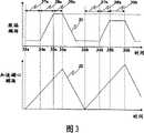
图3是致偏磁场和加速磁心磁场的时间变化模型1。 Figure 3 is the time variation model 1 of the biasing magnetic field and the magnetic field of the accelerating core. the
图4表示电子束能量和X射线的能量谱线。 Figure 4 shows electron beam energy and X-ray energy spectrum lines. the
图5是致偏磁场和加速磁心磁场的时间变化模型2。 Figure 5 is the time variation model 2 of the biasing magnetic field and the magnetic field of the accelerating core. the
图6是致偏磁场和加速磁心磁场的时间变化模型3。 Figure 6 is the time variation model 3 of the biasing magnetic field and the magnetic field of the accelerating core. the
具体实施方式Detailed ways
实施方式1 Implementation mode 1
图1、图2是分别表示实施方式1的电磁波发生装置的构成例1和构成例2的图。无论哪个例子在使用AG(Alternatig Gradient)聚焦加速器(图1根据非专利文献2(H.Tanaka,T.Nakanishi,”DESIGNAND CONSTRUCTION OF A SPIRAL MAGNET FOR A HYBRIDACCELERATOR”,Proceedings of the 1st Annual Meeting of ParticleAccelerator Society of Japan and the 29th Linear Accelerator Meetingin Japan(August4-6,2004,Funabashi Japan),465p-467p),图2根据专利文献2(专利公开号码2004-296164))这一点上是共同的,通过进行发挥其特征的规定的控制,能够实现高性能的电磁波发生装置。 FIG. 1 and FIG. 2 are diagrams showing configuration example 1 and configuration example 2 of the electromagnetic wave generator according to Embodiment 1, respectively. No matter which example is using AG (Alternatig Gradient) focusing accelerator (Figure 1 according to non-patent literature 2 (H.Tanaka, T.Nakanishi, "DESIGNAND CONSTRUCTION OF A SPIRAL MAGNET FOR A HYBRIDACCELERATOR", Proceedings of the 1st Annual Meeting of ParticleAccelerator Society of Japan and the 29th Linear Accelerator Meetingin Japan (August4-6, 2004, Funabashi Japan), 465p-467p), Fig. 2 is common on this point according to patent document 2 (patent publication number 2004-296164), by performing The characteristic predetermined control can realize a high-performance electromagnetic wave generating device. the
在图1中,11是发生电子束的电子发生单元,12是以在与纸面垂直的方向上夹着电子束行进轨道的形状,并且具有发生与纸面垂直方向的磁场的磁极的螺旋形状的螺旋磁极,13是回程磁轭,螺旋磁极12和回程磁轭13,虽然省略了记述但和围绕磁极的线圈形成偏转电磁铁(以下,称为螺旋偏转电磁铁)。14是发生用于加速回旋的电子束的交流磁场的加速磁心,15是通过和回旋电子束碰撞发生X射线的标 靶,16是入射时在本装置内的电子回旋轨道,17是回旋电子束不与标靶15碰撞的区域A和回旋电子束与标靶15碰撞的区域B的边界即边界电子回旋轨道,18是电子束能够稳定回旋的区域的最外周,19是在标靶15上发生的X射线等的电磁波(以下,作为X射线说明)。所发生的X射线的能量随着碰撞的电子束的能量而变化。 In Fig. 1, 11 is an electron generating unit that generates electron beams, and 12 is a spiral shape that sandwiches the electron beam travel path in a direction perpendicular to the paper surface and has magnetic poles that generate a magnetic field perpendicular to the paper surface. The helical magnetic pole 13 is a return yoke, and the helical magnetic pole 12 and the return yoke 13 form a deflection electromagnet (hereinafter referred to as a helical deflection electromagnet) with a coil surrounding the magnetic pole, although description is omitted. 14 is an accelerating magnetic core for generating an AC magnetic field for accelerating the gyrating electron beam, and 15 is a mark for generating X-rays by colliding with the gyrating electron beam.Target, 16 is the electron cyclotron orbit in the device when it is incident, 17 is the boundary between the region A where the cyclotron beam does not collide with the target 15 and the region B where the cyclotron beam collides with the target 15, that is, the boundary electron cyclotron, 18 19 is the outermost periphery of the region in which the electron beam can swirl stably, and 19 is electromagnetic waves such as X-rays generated on the target 15 (hereinafter, described as X-rays). The energy of the generated X-rays varies with the energy of the colliding electron beams. the
以下说明动作。 The operation will be described below. the
在电子发生单元11中发生的电子束如果入射到电磁波发生装置中,则由于受到螺旋偏转电磁铁的作用而偏转,一边在装置内回旋一边在加速磁心14的磁场中通过感应出的电场作用在图中的圆周方向上加速。本装置内的电子束在螺旋磁极12的部分上沿着大致圆弧轨道行进,没有螺旋磁极12的部分沿着接近直线的轨道行进,两轨道合在一起构成回旋轨道。在通过螺旋偏转电磁铁部分时的电子束的偏转半径根据伴随加速的电子束的能量的增加,和该偏转电磁铁的致偏磁场强度而变化。通常,和加速一同,偏转半径增大,电子回旋加速器轨道在半径方向上扩大。来自电子发生单元11的电子的入射因为在一定时间连续进行,所以初期入射的电子更向外侧轨道回旋,以后入射的电子在内侧的轨道上回旋,而在其间入射的电子在两轨道之间的轨道上回旋。因此,加速器内的电子在半径方向上扩展的回旋轨道上回旋。这一点和利用了电子回旋加速器加速装置的电磁波发生装置基本上不同。 If the electron beam generated in the electron generating unit 11 is incident on the electromagnetic wave generating device, it will be deflected by the action of the helical deflection electromagnet, and will be acted on by the induced electric field in the magnetic field of the accelerating magnetic core 14 while revolving in the device. Accelerate in the circumferential direction in the figure. The electron beam in the device travels along a roughly circular arc track on the part of the spiral magnetic pole 12, and travels along a nearly straight track on the part without the spiral magnetic pole 12, and the two tracks together form a convoluted track. The deflection radius of the electron beam when passing through the helical deflection electromagnet portion changes according to the energy increase of the electron beam accompanying the acceleration and the strength of the deflection magnetic field of the deflection electromagnet. Usually, along with the acceleration, the deflection radius increases, and the electron cyclotron orbit expands in the radial direction. Since the electrons from the electron generating unit 11 are injected continuously for a certain period of time, the electrons that are incident at the beginning revolve around the outer orbit, and the electrons that are incident thereafter revolve on the inner orbit, while the electrons that are incident in between revolve in the orbit between the two orbits. Turn around on the track. Therefore, the electrons in the accelerator revolve on a spiral orbit that expands in the radial direction. This point is basically different from an electromagnetic wave generator using an electron cyclotron accelerator. the
因为电子如此在半径方向上扩展的轨道上回旋,所以如果与在同一轨道上回旋的情况相比,则在回旋的电子束内的电子的密度减小,电子相互间作用库仑反作用力也减小。因此,与电子回旋加速器加速装置和存储环相比,可以入射利用大电流束。 Since the electrons swirl in orbits that expand in the radial direction in this way, the density of electrons in the swirling electron beam decreases and the Coulomb reaction force between electrons also decreases compared to the case of swirling in the same orbit. Therefore, compared with electron cyclotron accelerators and storage rings, it is possible to inject and utilize a large current beam. the
回旋的电子束在不碰撞的区域A内,在加速的同时使其回旋轨道在半径方向上逐渐扩展,直至加速到规定的能量后,通过以后说明的控制,越过边界回旋电子轨道17达到碰撞的区域B,碰撞到标靶15而放出X射线19。加速中的电子束因为在未设置标靶15的不碰撞区域A中回旋,所以电子束在加速途中由于与标靶15碰撞所以不会无 谓的损失。而且,标靶15在相对电子束回旋方向上,即相对X射线发生方向上变薄以便不使所发生的X射因在标靶15内自己吸收而减少。因为碰撞区域B也可以是电子束的稳定回旋的区域,所以即使在电子束和标靶15碰撞后,电子束中未碰撞的大部分电子能够继续稳定地回旋,依照电子束回旋轨道的控制方法,能够实现电子束和标靶15的反复碰撞。 In the non-collision area A, the gyrating electron beam gradually expands its gyrating orbit in the radial direction while accelerating until it accelerates to a specified energy, and then crosses the boundary gyrating electron orbit 17 to reach the collision point through the control described later. The region B collides with the target 15 and emits X-rays 19 . Since the accelerating electron beam is swirling in the non-collision area A where the target 15 is not provided, the electron beam will not fail due to collision with the target 15 during acceleration.so-called loss. Furthermore, the target 15 is thinned in the direction relative to the rotation direction of the electron beam, that is, in the direction relative to the generation of X-rays so as not to reduce the generation of X-rays due to self-absorption in the target 15 . Because the collision region B can also be a region where the electron beams are stably gyrating, even after the electron beams collide with the target 15, most of the uncollided electrons in the electron beams can continue to gyrate stably, according to the control method of the electron beam orbits , can realize the repeated collision of the electron beam and the target 15 . the
而且,在图1中电子发生单元11设置在电磁波发生装置的内部,但也可以把它设置在电磁波发生装置的下部,起到完全相同的效果。这和以后说明的图2所示的入射方式是同一种类,因为发生与加速磁心14的设置位置的干涉,所以电子发生单元11设置在例如加速装置的下部。 Moreover, the electron generating unit 11 is arranged inside the electromagnetic wave generating device in FIG. 1 , but it can also be arranged at the bottom of the electromagnetic wave generating device to achieve exactly the same effect. This is the same type of incidence as shown in FIG. 2 to be described later. Since interference with the installation position of the accelerating core 14 occurs, the electron generating unit 11 is installed, for example, at the lower part of the accelerating device. the
在此,在本申请的电磁波发生装置中使用的偏转电磁铁,因为其构成是,通过在半径方向上改变磁极间隔等在形状上下工夫,在实现在半径方向上倾斜的磁场的同时,利用使用螺旋磁极12的磁铁边界的边缘角和漏磁场来聚焦电子束的所谓的边缘聚焦,所以无论在不碰撞的区域A、碰撞区域B的哪个中都可以使电子束稳定回旋(非专利文献2),但并不是必须限定为螺旋磁极形状,只要是实现对半径方向的倾斜磁场,并能够还包含边缘形状保持对电子束的聚焦能力的磁极形状即可。 Here, the deflection electromagnet used in the electromagnetic wave generating device of the present application is constructed by changing the magnetic pole spacing in the radial direction, etc., to realize a magnetic field inclined in the radial direction, and to utilize The edge angle of the magnet boundary of the spiral magnetic pole 12 and the leakage magnetic field are used to focus the electron beam so-called edge focusing, so that the electron beam can be stably swirled in either the non-collision area A or the collision area B (Non-Patent Document 2) , but it is not necessarily limited to the spiral magnetic pole shape, as long as the magnetic pole shape can realize the gradient magnetic field in the radial direction, and can also include the edge shape to maintain the focusing ability of the electron beam. the
图2是用使用了不是螺旋形状的偏转电磁铁的AG聚焦加速装置构成的电磁波发生装置的1例。 Fig. 2 is an example of an electromagnetic wave generating device constituted by an AG focusing accelerator using a deflection electromagnet that is not a helical shape. the
在图2中,21是用于把来自电子发生单元11的电子束导入电磁波发生装置内的隔膜电极,22是用于使行进电子束的轨道偏转而形成回旋轨道的偏转电磁铁,23是加速电子束的加速磁心,24是电子束在其中回旋的真空管道,25a、b、c、d分别是真空管道24内的电子束的代表性的回旋轨道,26是用于向加速磁心23提供电力的加速磁心用电源,27是偏转电磁铁用电源,15是成为X射线发生源的标靶。 In Fig. 2, 21 is the diaphragm electrode that is used to guide the electron beam from the electron generating unit 11 into the electromagnetic wave generator, 22 is the deflection electromagnet that is used to deflect the orbit of the traveling electron beam to form a orbit, and 23 is the acceleration. The accelerating magnetic core of the electron beam, 24 is the vacuum pipeline in which the electron beam revolves, 25a, b, c, d are respectively the representative orbits of the electron beam in the vacuum pipeline 24, and 26 is used to provide electric power to the accelerating magnetic core 23 27 is a power supply for a deflection electromagnet, and 15 is a target to become an X-ray generating source. the
以下说明动作。 The operation will be described below. the
在电子发生单元11中发生的电子束经由隔膜电极21入射,在偏 转电磁铁23的部分中成为大致圆弧轨道形成回旋轨道。回旋电子束通过向加速磁心23施加交流磁场,由电磁感应产生的感应电场而被加速。电子在真空管道24中回旋。25a、b、c、d是电子束的代表性的回旋轨道。在这种情况下,也和图1的情况一样,在电子束能够稳定回旋的区域内,能够设定电子束不碰撞标靶15的区域A(回旋轨道25a、b所属的区域),和碰撞标靶15的区域B(回旋轨道25c、d所属的区域)。 The electron beam generated in the electron generating unit 11 is incident through the diaphragm electrode 21,In the part where the electromagnet 23 is rotated, a substantially circular arc orbit forms a revolving orbit. The cyclotron beam is accelerated by an induced electric field generated by electromagnetic induction by applying an AC magnetic field to the accelerating core 23 . The electrons swirl in the vacuum tube 24 . 25a, b, c, and d are representative orbits of electron beams. In this case, as in the case of FIG. 1 , in the region where the electron beam can stably swirl, the region A (the region to which the orbit 25a, b belongs) where the electron beam does not collide with the target 15 can be set, and the collision Region B of the target 15 (the region to which the orbits 25c, d belong). the
已入射的电子束在不碰撞的区域A内,按照入射时间在半径方向上扩展的轨道中回旋并加速。加速到规定的能量的电子和设置在碰撞区域B上的目标15碰撞产生X射线这一点和图1所示的例子一样。而且,在该图中虽然特别夸张放大描述半径方向的目标尺寸,但基本上和图1的例子一样。 In the non-collision area A, the incident electron beams revolve and accelerate in orbits that expand in the radial direction according to the incident time. Electrons accelerated to a predetermined energy collide with the target 15 placed in the collision area B to generate X-rays, as in the example shown in FIG. 1 . Moreover, although the size of the object in the radial direction is particularly exaggerated and enlarged in this figure, it is basically the same as the example in FIG. 1 . the
而且,在图2中电子发生单元11设置在加速装置的外部,虽然电子经由隔膜电极21入射到回旋轨道,但和图1所示的例子一样,即使配置在加速装置的内部也起到同样的效果,而且装置整体变得紧凑。 In addition, in FIG. 2, the electron generating unit 11 is provided outside the acceleration device. Although the electrons enter the orbit through the diaphragm electrode 21, as in the example shown in FIG. effect, and the device as a whole becomes compact. the
无论在图1、图2的哪个例子中,标靶15一般都是直径10μm左右的线形金属,更理想的是钨等的重金属,将其设置在该装置内使该线的长度方向与纸面正交的方向一致(在图中对半径方向进行了放大显示)。由此在确定半径方向的X射线发生源尺寸的同时,把在发生X射线的标靶15内的自吸收抑制为很小。但是,在线形标靶的情况下,线长度方向的X射线发生源的尺寸由行进的电子束的同一方向的尺寸确定,通常它的大小是数mm。为了减小它,还考虑将由碳等的低原子序数物质(包含有效原子序数)组成的线的中间安装了比该线原子序数(包含有效原子序数)高的,例如金属,更理想的是钨等的重金属的微小球粒的线作为标靶15。使用原子序数高的材料是因为能够增加X射线发生效率,并增大X射线强度,同时能够减小在2个方向上的光源尺寸的缘故。 No matter in which example of Fig. 1 and Fig. 2, the target 15 is generally a linear metal with a diameter of about 10 μm, more ideally heavy metals such as tungsten, and it is arranged in the device so that the length direction of the line is in line with the paper surface. Orthogonal directions coincide (the radial direction is shown enlarged in the figure). In this way, self-absorption in the target 15 that generates X-rays is suppressed to be small while determining the size of the X-ray generating source in the radial direction. However, in the case of a linear target, the size of the X-ray generating source in the line length direction is determined by the size of the traveling electron beam in the same direction, and its size is usually several mm. In order to reduce it, it is also considered to install a material with a higher atomic number (including effective atomic number) than the wire, such as a metal, preferably tungsten, in the middle of a line composed of a low atomic number substance (including effective atomic number) such as carbon. Lines of tiny spheroids of heavy metals such as the target 15 . The use of a material with a high atomic number is because the X-ray generation efficiency can be increased, the X-ray intensity can be increased, and the size of the light source in two directions can be reduced at the same time. the
接着,说明在利用了上述的AG聚焦加速装置的电磁波发生装置中的电子束的控制。无论在图1、图2的哪种情况下,电子束都可以 主要通过偏转电磁铁的磁场(以下简称为致偏磁场)的时间变化,和加速磁心磁场的时间变化的组合来控制其运动。 Next, the control of the electron beam in the electromagnetic wave generator using the above-mentioned AG focusing accelerator will be described. Regardless of the situation in Figure 1 or Figure 2, the electron beam canIts movement is mainly controlled by the combination of the time variation of the magnetic field of the deflection electromagnet (hereinafter referred to as the biasing magnetic field) and the time variation of the magnetic field of the accelerating core. the
图3是表示致偏磁场和加速磁心磁场的时间变化模型1的图。31表示致偏磁场的时间变化,32表示加速磁心的时间变化。它们都是横轴表示时间,用33a、33b表示的位置分别表示入射开始时间,用34a、34b表示的位置分别表示入射结束时间,用35a、35b表示的位置分别表示致偏磁场一定控制的开始时间,用36a、36b表示的位置分别表示致偏磁场一定控制的结束时间。用37a、37b表示的时间范围分别表示电子束的入射开始到结束的电子束入射时间,用38a、38b表示的范围分别表示在入射结束后,把电子束加速到规定能量的电子束加速时间。为了使分别已加速到规定能量的电子束碰撞标靶而进一步加速电子束,把电子束回旋轨道扩大到设置着标靶15的轨道,从而使电子束碰撞标靶15,用39a、39b表示的范围表示与维持该碰撞的时间对应的标靶碰撞时间。 FIG. 3 is a diagram showing a time-varying model 1 of a biasing magnetic field and an accelerating core magnetic field. 31 represents the temporal change of the biasing magnetic field, and 32 represents the temporal change of the accelerating magnetic core. They all represent time on the horizontal axis, the positions represented by 33a and 33b respectively represent the incident start time, the positions represented by 34a and 34b represent the incident end time respectively, and the positions represented by 35a and 35b represent the start of the constant control of the biasing magnetic field The time and the positions indicated by 36a and 36b indicate the end times of the constant deflection magnetic field control, respectively. The time ranges denoted by 37a and 37b respectively represent the electron beam incident time from the start to the end of the electron beam incident, and the ranges denoted by 38a and 38b respectively denote the electron beam acceleration time to accelerate the electron beam to a predetermined energy after the incident ends. In order to further accelerate the electron beams that have been accelerated to a predetermined energy to collide with the target, the orbit of the electron beam is expanded to the orbit where the target 15 is placed, so that the electron beam collides with the target 15, denoted by 39a, 39b The range represents the target collision time corresponding to the time the collision is maintained. the
致偏磁场的时间变化31和加速磁心磁场的时间变化32的关系不满足电子回旋加速器加速条件。所谓电子回旋加速器加速条件是加速中的电子束的回旋轨道为一定的致偏磁场和加速磁心磁场的关系。因而,所谓不满足电子回旋加速器加速条件就是加速中的电子束的回旋轨道未达到一定轨道。 The relationship between the
以下,首先说明在从33a到36a的时间范围中的电子束的动作。在入射开始时间33a时开始对电磁波发生装置内进行电子入射,在入射结束时间34a入射结束。此时,加速磁心磁场的时间变化在从入射开始时间33a开始的电子束入射时间37a期间,如图3下段的加速磁心磁场的时间变化32所示那样增加。由于加速磁心磁场的作用在电子束的行进方向上发生感应电场,入射的电子束在电子束入射时间37a期间也加速。在电子束入射时间37a的期间,致偏磁场一定,电子束如回旋轨道25a、25b所示那样,随着加速磁心磁场的增加而逐渐向外侧扩展。电子束因为在电子束入射时间37a的期间连续入射,所以在入射结束时间34a的时刻,在半径方向扩展的电子束回旋。在入射结 束时间34a中,在入射开始时间33a入射的电子束以最高能量回旋到最外侧附近的轨道(例如回旋轨道25b)。另外,在入射结束时间34a之前入射的电子束以最低能量在最内侧附近的轨道上(例如回旋轨道25a)回旋。即,在入射结束时间34a的时刻,电子具有规定的能量宽度,在半径方向上扩展的轨道上回旋。以往的电子回旋加速器装置是弱聚焦磁场,在半径不同的宽区域上难以得到一定的聚焦力,而在AG聚焦加速器的情况下,通过对偏转电磁铁的形状下功夫,因为能够在半径不同的宽广的区域上实现大致一定的聚焦力,所以能够自由改变回旋轨道。 Hereinafter, first, the operation of the electron beam in the time range from 33a to 36a will be described. Electron injection into the electromagnetic wave generating device starts at an
在入射结束时间34a之后转移到与电子束加速时间38a对应的状态。电子束在半径方向上具有幅宽,例如在偏转电磁铁部分中的圆弧轨道的半径从r1到r2的范围(假设r1<r2)中回旋,而在大于该r1小于r2的半径r0上,致偏磁场和加速磁心磁场保持接近电子回旋加速器加速条件进行变化。因而,如果电子束的能量因加速而变化,则上述r0之外回旋中的电子束聚集到r0周围。如果从宏观看则是在加速的同时,电子束尺寸一边逐渐减小一边加速。通过兼顾致偏磁场的增加速度和加速磁心磁场的增加速度,确定上述半径r0。电子束在规定的能量宽度,并且在半径方向上扩展的状态下得到加速。向着入射当初的半径方向的回旋轨道的扩展如上述那样在加速的同时减少,但轨道的扩展依然在剩下的状态下加速。无论怎样都在电子束加速时间38a内,把电子束的回旋轨道控制成停留在不碰撞的区域A的范围内。 After the
其后,在电子的最大能量达到规定值时,即在时间35a中,把致偏磁场设置为一定并转移到与标靶碰撞时间39a对应的状态。在此因为加速磁心磁场依然增加,所以电子束的回旋轨道进一步在半径方向扩大,把电子束引导到碰撞区域B,碰撞标靶15发生X射线。在此电子束因为在半径方向上扩展回旋,所以在标靶碰撞时间39a的期间,从最外回旋轨道的电子到在内侧轨道上回旋的电子顺序碰撞标靶15,而因为对电子束回旋轨道的半径方向上的扩大速度并不大,所以与回旋电子束为了在半径方向上横切轨道上的标靶15所需要的时间相比, 电子束回旋1圈所需要的时间明显很短。因而,电子束在和标靶15碰撞的轨道上回旋多圈。而后,因为设置有标靶的碰撞区域B是稳定回旋区域,所以电子束在标靶碰撞时间39a期间稳定地连续回旋。其结果,可以高效率地把回旋电子束变换为X射线。 Thereafter, when the maximum energy of electrons reaches a predetermined value, that is, during
这样稳定地回旋并反复碰撞标靶这一点和利用了以往的电子回旋加速器加速装置的电磁波发生装置有很大不同。与存储环相比,同样在回旋轨道的扩展这一点上有很大不同。总之,因为靠该特征成为适宜于大电流束的加速的装置,所以起到在小型的装置中能够产生大强度的X射线的效果。 This point of stably orbiting and repeatedly colliding with the target is very different from the electromagnetic wave generator using the conventional electron cyclotron accelerator. Compared with the storage ring, there is also a big difference in the expansion of the orbital orbit. In short, since this feature makes it suitable for accelerating a large current beam, it is possible to generate high-intensity X-rays in a compact device. the
在以上的说明中,把在图3的标靶碰撞时间39a中的致偏磁场的时间变化31作为是一定的进行了说明,但因为致偏磁场和加速磁心磁场的关系只要根据电子回旋加速器加速条件错开即可,所以并不限定为一定,也可以设置成和时间一同逐渐增加的致偏磁场。这种情况下的电子束的动作和标靶的碰撞和此间致偏磁场的时间变化是一定的情况基本上相同,而向回旋轨道的半径方向扩大的速度变得缓慢。其结果,如果进行这样的控制,因为能够延长回旋的电子束和标靶15的碰撞时间,所以回旋电子束向X射线的变换效率进一步提高。 In the above description, the
经过标靶碰撞时间39a后,因为和标靶15的碰撞电子束通常大致消失。因此其后,使致偏磁场和加速磁心磁场返回初始状态的过程没有特别的限制事项。在图3中在时间36a以后,以和加速时同等程度的速度减少两磁场,但并不拘泥于此。在使致偏磁场和加速磁心磁场返回入射时的状态后,再次重复电子束的入射过程以后的步骤,通过每次使新的电子入射、加速并碰撞标靶,能够连续发生X射线。 After the
在该重复过程中,还可以使致偏磁场和加速磁心的时间变化模型每次相同,但也可以在每次入射时变化。从图3的时间33b到36b表示该例子。在图3的第2次入射中,表示使致偏磁场设置成一定的时刻比第1次入射时还提前的例子。图3的电子束加速时间38b设定为比38a还小的值。如果设置成致偏磁场、加速磁心磁场的时间变化的倾斜在第1次和第2次中相同,则通过把电子束加速时间38b设定得 小,在第2次的情况下就可以以小的致偏磁场值保持一定值。因而,在时间35b中,与电子束与在时间35a中的电子束能量相比,处于低能量的状态。 In this repeated process, the time variation model of the biasing magnetic field and the accelerating magnetic core can also be made the same every time, but it can also be changed every time it is incident. This example is shown from
在该状态下,由增加的加速磁心磁场的作用电子束进一步加速,因为致偏磁场保持为一定值,所以向着回旋轨道的半径方向的扩大速度与第1次相比更快。于是,电子束因为更早地达到碰撞区域B并和标靶15碰撞,所以和标靶15碰撞的电子束的能量的值比第1次和标靶15碰撞的电子束的能量还低。这样就能够容易改变与标靶15碰撞的电子束的能量。而且,达到时间35a或者35b时,电子束并不立即与标靶15碰撞,在达到时间35a,或者35b的时刻,根据电子束回旋轨道和标靶15的半径方向的距离的大小程度,碰撞开始的时间变化。即,严格地说从时间35a或者35b开始经过规定时间后发生X射线。 In this state, the electron beam is further accelerated by the action of the increasing magnetic field of the accelerating core, and since the biasing magnetic field is maintained at a constant value, the expansion speed toward the radial direction of the orbit is faster than that of the first time. Therefore, since the electron beam reaches the collision area B earlier and collides with the target 15 , the energy value of the electron beam colliding with the target 15 is lower than the energy value of the electron beam colliding with the target 15 for the first time. This makes it possible to easily vary the energy of the electron beams colliding with the target 15 . Moreover, when the
图4是概略表示在碰撞的电子束的能量高时和低时在标靶15上发生的X射线的能量谱变化的状况的图。从该图中可知,使高能量的电子束碰撞标靶15时的一方能够发生更高能量的X射线。通过这样控制与标靶15碰撞的电子的能量,能够控制所发生的X射线的能量。 FIG. 4 is a diagram schematically showing how the X-ray energy spectrum changes on the target 15 when the energy of the colliding electron beams is high and low. As can be seen from this figure, X-rays with higher energy can be generated when the high-energy electron beam collides with the target 15 . By controlling the energy of the electrons colliding with the target 15 in this way, the energy of the generated X-rays can be controlled. the
而且,虽然在上述例子中设置成靠加速磁心磁场产生的感应电场来加速电子束,但即使把它变为采用高频电场的加速单元也能够起到同样的效果。这在以后说明的全部的实施方式中也同样成立。 Moreover, although the electron beam is accelerated by the induced electric field generated by the magnetic field of the accelerating core in the above example, the same effect can be achieved even if it is changed to an accelerating unit using a high-frequency electric field. This also applies to all the embodiments described below. the
另外,在上述例子中假设入射中致偏磁场是一定的,在达到时间34a、34b时致偏磁场突然以一定斜度开始增加,而如果是可以入射的条件则不需要必须把致偏磁场设定为一定,另外也可以从入射时的磁场开始设置平滑期间,使在时间34a、34b的时刻的致偏磁场的变化逐渐增加。即使这样,上述的电子束的基本的动作也不变。 In addition, in the above example, it is assumed that the incident biasing magnetic field is constant, and when the
进而,在上述的例子中有磁极的部分的轨道是圆弧,没有磁极的部分的轨道大致是直线,而即使是没有磁极的部分也在致偏磁场的强度大时有时成为圆弧。但是与有磁极的部分的圆弧相比成为半径大的圆弧。即使这样,相对上述的标靶15的电子束的基本的动作也不改变。 Furthermore, in the above example, the track of the portion with magnetic poles is a circular arc, and the track of the portion without magnetic poles is approximately a straight line, and even the portion without magnetic poles sometimes becomes a circular arc when the strength of the biasing magnetic field is high. However, the circular arc has a larger radius than the circular arc of the portion having the magnetic poles. Even so, the basic movement of the electron beam relative to the target 15 described above does not change. the
如上所述,如果采用该实施方式,则在该装置中能够加速大电流, 在X射线发生中也能够在稳定的条件下使电子束回旋,也因为容易改变碰撞标靶15的电子束的能量,所以在能够容易实现大强度的X射线源的同时,还能够容易改变所发生的X射线的能量。而且,因为能够如此改善X射线发生强度,所以在各种X射线利用时,可以谋求照射时间的缩短化,和测量等的高速化。另外,即使把标靶微型化也能够发生实质上可以利用的强度的X射线,还能够实现X射线发生源尺寸的微型化。由此,当把该微小的X射线发生源例如用于得到X射线拍摄图像的目的时,与以往的X射线发生源相比能够得到解像度高的摄像图像。具体地说还取决于装置规模,但可以实现具有在10μm左右的光源尺寸下可以利用的X射线强度的装置。 As mentioned above, if this embodiment is adopted, a large current can be accelerated in this device,Also in X-ray generation, the electron beam can be swirled under stable conditions, and because it is easy to change the energy of the electron beam colliding with the target 15, it is easy to realize a high-intensity X-ray source, and it is also possible to easily change the energy of the electron beam. The energy of the X-rays that occur. Furthermore, since the intensity of X-ray generation can be improved in this way, it is possible to shorten the irradiation time and speed up measurement and the like when using various X-rays. In addition, even if the target is miniaturized, X-rays of substantially usable intensity can be generated, and the size of the X-ray generating source can also be miniaturized. Therefore, when this tiny X-ray generator is used for the purpose of obtaining an X-ray photographed image, for example, it is possible to obtain a photographed image with higher resolution than a conventional X-ray generator. Specifically, depending on the scale of the device, it is possible to realize a device having an X-ray intensity that can be used with a light source size of about 10 μm. the
另外,通过采用具有聚焦功能的偏转电磁铁,因为能够使加速装置大幅度小型化,所以与利用了以往类型加速器的电磁波发生装置相比能够大幅度的小型化。其结果,能够实现在各种利用时方便的,易于使用的光源。另外,通过其小型化,还可以一并实现低成本化。这一点在小型化的同时,大大有助于因使偏转电磁铁具有聚焦功能而带来的构造的简单化。 In addition, since the accelerator device can be greatly reduced in size by using a deflection electromagnet having a focusing function, it can be significantly reduced in size compared with an electromagnetic wave generator using a conventional accelerator. As a result, an easy-to-use light source that is convenient for various uses can be realized. In addition, the reduction in cost can also be achieved through its miniaturization. This greatly contributes to the simplification of the structure brought by the focusing function of the deflection electromagnet while miniaturization. the
实施方式2 Implementation mode 2
本实施方式是把入射时对电子束回旋轨道的半径方向的扩展的程度与实施方式1的情况比较增大的形态。图5表示这种情况下的致偏磁场和加速磁心磁场的时间变化模型的例子。在图中,号码相同的部分和图3的说明一样。图5的第1次电子入射的例子是在全过程中把致偏磁场的时间变化31作为一定的例子。在这种情况下,伴随加速的电子束向回旋轨道的半径方向扩大比图3的情况还大。图5的第2次电子入射的例子是在电子束的入射时使致偏磁场减少的例子。在这种情况下,伴随加速的电子束向回旋轨道的半径方向的扩大比把致偏磁场设置成一定时进一步变大。无论在哪种情况下,都存在为了把电子束加速到规定的能量所需要的装置尺寸大这一缺点,而相反因为回旋轨道上的电子束密度降低,所以能够加长电子的入射时间入射大电流。因而,可以加速更大的电流束,与实施方式1的情况相比能够进 一步增大X射线强度。另外,除上述方面以外具有和在实施方式1中说明的效果相同的效果。 This embodiment is a form in which the degree of expansion in the radial direction of the orbit of the electron beam at the time of incidence is increased compared to the case of the first embodiment. Fig. 5 shows an example of the temporal variation model of the biasing magnetic field and the accelerating core magnetic field in this case. In the drawings, the parts with the same numbers are the same as those in the description of FIG. 3 . The example of the first incident of electrons in FIG. 5 takes the
实施方式3 Implementation mode 3
实施方式3是通过不经过电子的再次入射而高速改变电子束的能量,来实现高速切换所发生的X射线的能量的方式。图6表示这种情况下的致偏磁场和加速磁心磁场的时间变化模型的例子。在图中从31到39a的说明和图3的情况一样。在此,36a在表示致偏磁场一定控制结束时间的同时,还是相当于电子束加速时间38a的电子束再加速时间43a的开始时间。41a在是电子束再加速时间43a的结束的时间的同时,还是相当于标靶碰撞时间39a的标靶再碰撞时间44a的开始时间。而后,42a是标靶再碰撞时间44a的结束时间。 Embodiment 3 is a mode in which high-speed switching of the energy of generated X-rays is realized by changing the energy of electron beams at high speed without re-incidence of electrons. Fig. 6 shows an example of the temporal variation model of the biasing magnetic field and the accelerating core magnetic field in this case. The description from 31 to 39a in the figure is the same as in the case of FIG. 3 . Here, 36a indicates the start time of the electron beam
以下说明动作。 The operation will be described below. the
从时间33a到36a的过程和图3的情况相同。不同之处在于,在标靶碰撞时间39a的时间过程中再次设置相当于电子束加速时间38a的电子束再加速时间43a,在电子束从和标靶15的碰撞位置一旦错过的同时,被再次加速,此后再次返回到标靶15的位置。 The process from
即,在标靶碰撞时间39a内,在回旋电子束还没有完全消失的状态中,增加致偏磁场。通过使此时的增加程度比在电子束加速时间38a内的致偏磁场的增加速度还大,使电子束的回旋轨道半径缩小。由此,回旋电子束后退到不碰撞的区域A。虽然此间由于加速磁心磁场逐渐增加所以电子束被逐渐加速,其能量增加,但回旋轨道维持在该不碰撞的区域A内。而后,在达到规定的能量的时刻41a再次使致偏磁场为一定。于是,由于加速磁心的磁场增加,电子束的能量进一步增加,回旋轨道在半径方向上扩大,电子束以比在标靶碰撞时间39a中的电子束还高的能量,碰撞设置在碰撞区域B上的标靶15。 That is, within the
这样能够容易而且高速地改变在标靶碰撞时间39a内和标靶再碰撞时间44a内发生的X射线能量。在该例子中在标靶再碰撞时间44a内发生的X射线能量比在标靶碰撞时间39a内发生的X射线能量还高。 This enables an easy and high-speed change of the X-ray energy occurring during the
而且,在标靶碰撞时间39a和标靶再碰撞时间44a中的致偏磁场的时间变化无须控制为一定,也可以和时间一同增加。其效果以及其他的效果和在实施方式1中说明的效果相同。 Furthermore, the time variation of the deflecting magnetic field in the
实施方式4 Implementation Mode 4
在实施方式1到3中都说明了从电磁波发生装置的内侧入射电子束的例子,但并不限于此,也可以是在电磁波发生装置的外周附近设置电子发生单元11,从电磁波发生装置的外周附近入射来自电子发生装置11的电子束。为了实现这样的入射,伴随入射时和加速必须在半径方向上缩小电子束的回旋轨道。用图3说明它。 In Embodiments 1 to 3, the example in which the electron beam is incident from the inside of the electromagnetic wave generator is described, but it is not limited to this, and the electron generating unit 11 may be provided near the outer periphery of the electromagnetic wave generator, and the electron beam may be emitted from the outer periphery of the electromagnetic wave generator Electron beams from the electron generating device 11 are incident nearby. In order to achieve such an incident, it is necessary to reduce the orbit of the electron beam in the radial direction accompanying the incident time and acceleration. Use Figure 3 to illustrate it. the
首先在电子束入射时间37a内的致偏磁场不是一定的,其必须和时间一同增加。由于加速磁心磁场增加产生的电子束能量的增加的作用,当致偏磁场是一定的情况下,回旋轨道正在向半径方向上扩大时,通过使致偏磁场和加速一同增加,相反使回旋轨道在半径方向上缩小。 Firstly, the biasing magnetic field within the electron
另外,在相当于电子束加速时间38a的时间内的致偏磁场的时间变化由于也比图3所示的时间变化更剧烈地增加,因而即使在入射结束后的加速过程中也可以和加速一同在半径方向上缩小电子束的回旋轨道。而后,成为X射线发生源的标靶15在这种情况下设置在内侧的回旋轨道上。在时间35a加速到规定的能量,使在内侧的规定回旋轨道附近回旋的电子必须碰撞进一步设置在其内侧上的标靶15。因此,在标靶碰撞时间39a内,需要一边加速电子束或者一边保持一定能量,一边增加致偏磁场,使电子束的回旋轨道进一步向内侧缩小,将其实现是容易的。通过在标靶碰撞时间39a内使该状态继续,使得在轨道上扩展回旋的电子束顺序碰撞标靶,从而发生X射线。 In addition, since the time variation of the deflecting magnetic field in the time corresponding to the electron
而且,在上述例子中是把标靶15配置在内侧的回旋轨道上,但也可以在外侧上。在这种情况下因为入射之后的电子束碰撞标靶15,所以标靶部分需要制成在短时间通过的入射条件,而通过控制致偏磁场和加速磁心磁场的时间变化模型容易实现。在这种情况下,碰撞标靶15的区域B所在位置比未碰撞的区域A还靠外侧。在入射时快速通过该区域B的电子束在A区域上加速,由于减弱致偏磁场因而再次 回旋到区域B。能够利用由于此时和标靶15碰撞而发生的X射线。 Furthermore, in the above example, the target 15 is arranged on the inner orbit, but it may be arranged on the outer side. In this case, since the electron beam after the incident collides with the target 15, the target part needs to be made to pass through the incident condition in a short time, which is easily realized by controlling the time variation model of the biasing magnetic field and the accelerating core magnetic field. In this case, the area B where the target 15 collided is located further outside than the area A where the target 15 did not collide. The electron beam that passes through this area B rapidly at the time of incidence is accelerated on the area A, due to the weakening of the biasing magnetic field and thus againRoundabout to area B. X-rays generated by colliding with the target 15 at this time can be utilized. the
在每次入射时,为了改变碰撞标靶的电子能量只要改变致偏磁场和加速磁心磁场的时间变化模型即可。另外,在1次入射时可以改变碰撞标靶15的电子束能量这一点也和实施方式3的情况一样,只要改变致偏磁场和加速磁心磁场的时间变化模型即可。作为这样的X射线发生源的特性是由于该电磁波发生装置在半径方向上具有宽阔并且稳定的回旋轨道而产生的,在利用以往的电子回旋加速器等的电磁波发生装置中无论如何也无法实现。 In each incident, in order to change the energy of the electrons colliding with the target, it is only necessary to change the time variation model of the biasing magnetic field and the magnetic field of the accelerating core. Also, as in the case of Embodiment 3, the energy of the electron beam colliding with the target 15 can be changed for one incident, and only the temporal variation models of the biasing magnetic field and the accelerating core magnetic field can be changed. The characteristics of such an X-ray generator are due to the fact that the electromagnetic wave generator has a wide and stable orbit in the radial direction, and cannot be realized by any conventional electromagnetic wave generator using an electron cyclotron or the like. the
通过这样采用从装置外周附近入射电子束的方式,可以使电子发生单元11的配置自由度提高,作为整体能够实现紧凑的装置。其他效果和实施方式与1、3所述的相同。 By adopting the method of injecting electron beams from the vicinity of the outer periphery of the device in this way, the degree of freedom in arrangement of the electron generating unit 11 can be improved, and a compact device can be realized as a whole. Other effects and embodiments are the same as those described in 1 and 3. the
实施方式5 Implementation Mode 5
本实施方式是指在保持电子束的能量的状态下,使电子束在不碰撞的区域A和碰撞区域B之间往来的方式。用图6说明。在图6中,在标靶碰撞时间39a和标靶再碰撞时间44a中电子束的能量不同,而通过在电子束加速时间43a中控制加速磁心磁场,能够在把电子束的能量保持为一定值的状态下通过致偏磁场的增减改变回旋轨道。 The present embodiment refers to a method in which electron beams are made to travel between the non-collision area A and the collision area B while maintaining the energy of the electron beams. Use Figure 6 to illustrate. In FIG. 6, the energy of the electron beam is different between the
而且至此,说明了未碰撞的区域A和碰撞区域B分别只考虑为1个区域,电子束在区域A和区域B的回旋轨道的来往的情况。但是,把在标靶15的设置位置上回旋的轨道作为碰撞区域B,对于和标靶的碰撞区域B,在半径方向上,还在和此前说明的未碰撞的区域A相反一侧上设定不和标靶15碰撞的区域A1,通过控制致偏磁场和加速磁心磁场的时间变化模型,在区域A、B、A1之间使电子束在回旋轨道上移动,能够控制X射线发生的通/断(ON/OFF)。另外,此时,如此前说明的那样,因为能够改变电子束的能量,所以能够高速切换和上述通/断一致产生的X射线的能量。 And so far, the case where the non-collision area A and the collision area B are considered as only one area, and the electron beam travels between the orbits of the area A and the area B has been described. However, the trajectory that revolves around the installation position of the target 15 is used as the collision area B, and the collision area B with the target is also set on the opposite side to the non-collision area A described above in the radial direction. In the area A1 that does not collide with the target 15, by controlling the time-varying model of the biasing magnetic field and the magnetic field of the accelerating core, the electron beam is moved on the orbit between the areas A, B, and A1, and the passage/passage of X-rays can be controlled. off (ON/OFF). In addition, at this time, as described above, since the energy of the electron beam can be changed, the energy of the X-rays generated in accordance with the above-mentioned on/off can be switched at high speed. the
Claims (6)
Applications Claiming Priority (3)
| Application Number | Priority Date | Filing Date | Title |
|---|---|---|---|
| JP2005-128120 | 2005-04-26 | ||
| JP2005128120AJP4639928B2 (en) | 2005-04-26 | 2005-04-26 | Electromagnetic wave generator |
| JP2005128120 | 2005-04-26 |
Publications (2)
| Publication Number | Publication Date |
|---|---|
| CN1856212A CN1856212A (en) | 2006-11-01 |
| CN1856212Btrue CN1856212B (en) | 2012-07-04 |
Family
ID=37195918
Family Applications (1)
| Application Number | Title | Priority Date | Filing Date |
|---|---|---|---|
| CN2006100754042AExpired - Fee RelatedCN1856212B (en) | 2005-04-26 | 2006-04-14 | Electromagnetic wave generating device |
Country Status (3)
| Country | Link |
|---|---|
| US (1) | US7310409B2 (en) |
| JP (1) | JP4639928B2 (en) |
| CN (1) | CN1856212B (en) |
Families Citing this family (30)
| Publication number | Priority date | Publication date | Assignee | Title |
|---|---|---|---|---|
| US7963695B2 (en) | 2002-07-23 | 2011-06-21 | Rapiscan Systems, Inc. | Rotatable boom cargo scanning system |
| US7471764B2 (en) | 2005-04-15 | 2008-12-30 | Rapiscan Security Products, Inc. | X-ray imaging system having improved weather resistance |
| JP5194523B2 (en)* | 2007-04-02 | 2013-05-08 | 三菱電機株式会社 | X-ray generator |
| JP5183115B2 (en)* | 2007-07-20 | 2013-04-17 | 三菱電機株式会社 | X-ray generator |
| JP2012209119A (en)* | 2011-03-29 | 2012-10-25 | Mitsubishi Heavy Ind Ltd | X-ray generator and control method thereof |
| CN102789943A (en)* | 2011-05-18 | 2012-11-21 | 苏州生物医学工程技术研究所 | X-ray tube system and operation method thereof |
| CA2863382C (en)* | 2011-06-09 | 2017-06-27 | Rapiscan Systems, Inc. | System and method for x-ray source weight reduction |
| US9218933B2 (en)* | 2011-06-09 | 2015-12-22 | Rapidscan Systems, Inc. | Low-dose radiographic imaging system |
| US8803453B2 (en)* | 2011-06-22 | 2014-08-12 | Varian Medical Systems, Inc. | Accelerator system stabilization for charged particle acceleration and radiation beam generation |
| KR101973221B1 (en) | 2011-09-07 | 2019-04-26 | 라피스캔 시스템스, 인코포레이티드 | X-ray inspection system that integrates manifest data with imaging/detection processing |
| DE102012109453A1 (en)* | 2012-10-04 | 2014-04-10 | Helmholtz-Zentrum Dresden - Rossendorf E.V. | Arrangement for generating mono-energetic single electron, has tungsten wire support portion whose inner diameter is set larger than the diameter of high current primary beam |
| GB2532902B (en) | 2013-07-23 | 2020-06-03 | Rapiscan Systems Inc | Methods for improving processing speed for object inspection |
| US9338875B2 (en)* | 2013-08-07 | 2016-05-10 | Varian Medical Systems, Inc. | Interlaced multi-energy betatron with adjustable pulse repetition frequency |
| WO2015105541A1 (en)* | 2013-09-19 | 2015-07-16 | Rapiscan Systems, Inc. | Low-dose radiographic inspection system |
| US10508998B2 (en) | 2014-05-08 | 2019-12-17 | Lawrence Livermore National Security, Llc | Methods for 2-color radiography with laser-compton X-ray sources |
| WO2015171927A1 (en) | 2014-05-08 | 2015-11-12 | Lawrence Livermore National Security, Llc | Ultralow-dose, feedback imaging with laser-compton x-ray and laser-compton gamma-ray sources |
| CN103984035A (en)* | 2014-05-15 | 2014-08-13 | 北京君和信达科技有限公司 | A dual-mode speed-through radiation inspection system and method for moving targets |
| WO2016003547A1 (en) | 2014-06-30 | 2016-01-07 | American Science And Engineering, Inc. | Rapidly relocatable modular cargo container scanner |
| US10345479B2 (en) | 2015-09-16 | 2019-07-09 | Rapiscan Systems, Inc. | Portable X-ray scanner |
| CN116309260A (en) | 2016-02-22 | 2023-06-23 | 拉皮斯坎系统股份有限公司 | Method for evaluating average pallet size and density of goods |
| CN109691238B (en) | 2016-07-14 | 2024-02-13 | 拉皮斯坎系统股份有限公司 | System and method for improving penetration of a radiological imaging scanner |
| KR102322475B1 (en)* | 2016-10-20 | 2021-11-08 | 폴 슈레 앙스띠뛰 | Multi-undulator spiral miniature light source |
| US10600609B2 (en) | 2017-01-31 | 2020-03-24 | Rapiscan Systems, Inc. | High-power X-ray sources and methods of operation |
| CN108882498B (en)* | 2018-07-04 | 2019-12-24 | 中国原子能科学研究院 | A strong magnetic field synchrocyclotron and its magnetic field shim method |
| US11212902B2 (en) | 2020-02-25 | 2021-12-28 | Rapiscan Systems, Inc. | Multiplexed drive systems and methods for a multi-emitter X-ray source |
| US11193898B1 (en) | 2020-06-01 | 2021-12-07 | American Science And Engineering, Inc. | Systems and methods for controlling image contrast in an X-ray system |
| MX2023009276A (en) | 2021-02-23 | 2023-10-10 | Rapiscan Systems Inc | SYSTEMS AND METHODS FOR ELIMINATING CROSSTALK SIGNALS IN ONE OR MORE SCANNING SYSTEMS THAT HAVE MULTIPLE X-RAY SOURCES. |
| CN113660762A (en)* | 2021-09-20 | 2021-11-16 | 三兄弟(珠海)科技有限公司 | Quantum state electromagnetic wave generating device for material detection |
| WO2023150418A2 (en) | 2022-02-03 | 2023-08-10 | Rapiscan Holdings, Inc. | Systems and methods for real-time energy and dose monitoring of an x-ray linear accelerator |
| EP4562413A1 (en) | 2022-07-26 | 2025-06-04 | Rapiscan Holdings, Inc. | Methods and systems for performing on-the-fly automatic calibration adjustments of x-ray inspection systems |
Citations (1)
| Publication number | Priority date | Publication date | Assignee | Title |
|---|---|---|---|---|
| US5680018A (en)* | 1994-11-16 | 1997-10-21 | Research Development Corporation Of Japan | Method and apparatus for generating radiation |
Family Cites Families (3)
| Publication number | Priority date | Publication date | Assignee | Title |
|---|---|---|---|---|
| CN1943284A (en)* | 2002-10-25 | 2007-04-04 | 独立行政法人科学技术振兴机构 | Electron accelerator and radiotherapy apparatus using same |
| US7259529B2 (en) | 2003-02-17 | 2007-08-21 | Mitsubishi Denki Kabushiki Kaisha | Charged particle accelerator |
| JP2004296164A (en)* | 2003-03-26 | 2004-10-21 | Mitsubishi Electric Corp | Power supply for the bending magnet and charged core for the charged particle accelerator |
- 2005
- 2005-04-26JPJP2005128120Apatent/JP4639928B2/ennot_activeExpired - Fee Related
- 2006
- 2006-04-14CNCN2006100754042Apatent/CN1856212B/ennot_activeExpired - Fee Related
- 2006-04-20USUS11/407,332patent/US7310409B2/ennot_activeExpired - Fee Related
Patent Citations (1)
| Publication number | Priority date | Publication date | Assignee | Title |
|---|---|---|---|---|
| US5680018A (en)* | 1994-11-16 | 1997-10-21 | Research Development Corporation Of Japan | Method and apparatus for generating radiation |
Non-Patent Citations (1)
| Title |
|---|
| JP特开2004-296164A 2004.10.21 |
Also Published As
| Publication number | Publication date |
|---|---|
| JP4639928B2 (en) | 2011-02-23 |
| US20060249685A1 (en) | 2006-11-09 |
| US7310409B2 (en) | 2007-12-18 |
| JP2006309968A (en) | 2006-11-09 |
| CN1856212A (en) | 2006-11-01 |
Similar Documents
| Publication | Publication Date | Title |
|---|---|---|
| CN1856212B (en) | Electromagnetic wave generating device | |
| JP2006309968A5 (en) | ||
| JP5665721B2 (en) | Circular accelerator and operation method of circular accelerator | |
| JP4691576B2 (en) | Particle beam therapy system | |
| JPH11513528A (en) | Method for extracting charged particles from isochronous cyclotron and apparatus applying this method | |
| JPH10233299A (en) | Charged particle beam expander | |
| JP4622977B2 (en) | Circular accelerator, electromagnetic wave generator, and electromagnetic wave imaging system | |
| TWI577414B (en) | Circular accelerator, operation method thereof and particle beam therapy appartus | |
| KR101044698B1 (en) | X-ray generator and method using electron eddy resonance ion source device | |
| WO2023013458A1 (en) | Circular accelerator and particle beam treatment system | |
| JP4650382B2 (en) | Charged particle beam accelerator and particle beam irradiation system using the charged particle beam accelerator | |
| WO2017145259A1 (en) | Heavy particle radiation therapy apparatus | |
| JP2019096404A (en) | Circular accelerator and particle therapy system | |
| US3390293A (en) | High energy particle generator | |
| JP2012142139A (en) | Ion beam generation method and ion beam generation apparatus | |
| US4789839A (en) | Method and apparatus for injecting charged particles across a magnetic field | |
| JP2006127822A (en) | Circular charged particle accelerator and method of operating the circular charged particle accelerator | |
| JP6663618B2 (en) | Accelerator and particle beam irradiation device | |
| WO1987001900A1 (en) | Method of introducing charged particles into magnetic resonance type accelerator and magnetic resonance type accelerator based on said method | |
| JP3919674B2 (en) | Accelerator system | |
| Keefe | Collective-effect accelerators | |
| JPH01204399A (en) | Electron accelerator | |
| JPS62139300A (en) | Method of taking out emitted light of cynchrotron and electron wave ring employing the method | |
| JP2843689B2 (en) | Electron accelerator | |
| JP2001052896A (en) | Particle accelerating and accumulating device |
Legal Events
| Date | Code | Title | Description |
|---|---|---|---|
| C06 | Publication | ||
| PB01 | Publication | ||
| C10 | Entry into substantive examination | ||
| SE01 | Entry into force of request for substantive examination | ||
| C14 | Grant of patent or utility model | ||
| GR01 | Patent grant | ||
| CF01 | Termination of patent right due to non-payment of annual fee | ||
| CF01 | Termination of patent right due to non-payment of annual fee | Granted publication date:20120704 Termination date:20160414 |