CN1855332A - Backlit key assembly - Google Patents
Backlit key assemblyDownload PDFInfo
- Publication number
- CN1855332A CN1855332ACN 200510067491CN200510067491ACN1855332ACN 1855332 ACN1855332 ACN 1855332ACN 200510067491CN200510067491CN 200510067491CN 200510067491 ACN200510067491 ACN 200510067491ACN 1855332 ACN1855332 ACN 1855332A
- Authority
- CN
- China
- Prior art keywords
- light
- key
- button
- button assembly
- guide device
- Prior art date
- Legal status (The legal status is an assumption and is not a legal conclusion. Google has not performed a legal analysis and makes no representation as to the accuracy of the status listed.)
- Pending
Links
- 239000000463materialSubstances0.000claimsdescription6
- 229920000515polycarbonatePolymers0.000claimsdescription5
- 238000005452bendingMethods0.000claimsdescription3
- 239000004425MakrolonSubstances0.000claims2
- -1acrylChemical group0.000claims2
- NIXOWILDQLNWCW-UHFFFAOYSA-Nacrylic acid groupChemical groupC(C=C)(=O)ONIXOWILDQLNWCW-UHFFFAOYSA-N0.000description4
- 239000004417polycarbonateSubstances0.000description4
- 238000003825pressingMethods0.000description3
- 239000010409thin filmSubstances0.000description3
- 238000010586diagramMethods0.000description2
- 238000005516engineering processMethods0.000description2
- 239000010408filmSubstances0.000description2
- 230000005540biological transmissionEffects0.000description1
- 230000003247decreasing effectEffects0.000description1
- 230000000694effectsEffects0.000description1
- 150000002148estersChemical class0.000description1
- 238000000034methodMethods0.000description1
- 238000005457optimizationMethods0.000description1
- 229920001690polydopaminePolymers0.000description1
Images


Landscapes
- Push-Button Switches (AREA)
- Switch Cases, Indication, And Locking (AREA)
Abstract
Description
Translated fromChinese【技术领域】【Technical field】
本发明涉及一种具有背光的按键,特别是涉及一种背光型按键总成。The invention relates to a key with backlight, in particular to a backlight key assembly.
【背景技术】【Background technique】
随着科技的进步,电子产品的应用越来越广泛,在一些光线不足的场所,例如会议中、汽车和飞机上,在使用如电脑、PDA、投影机、手机等电子产品时,常常因为环境中光线的不足而造成按键操作上的不便与困难。With the advancement of science and technology, the application of electronic products is more and more extensive. In some places with insufficient light, such as in meetings, cars and airplanes, when using electronic products such as computers, PDAs, projectors, mobile phones, etc., often due to the environment Insufficient light in the center causes inconvenience and difficulty in key operation.
为了解决上述问题,中国台湾新型第M248011号专利揭露了一种可发光的按键开关,其是于按键本体采用透光式设计,且按键本体的至少任一侧边处向外延伸设有导柱,而电路板正对应于按键本体的位置处则设有发光元件,电路板再对应于导柱的位置设有相接触的微动开关,当按压开关按键时,导柱会一同按压微动开关而形成开启状态,使发光元件发亮,而光线直接投射在按键本体上,使按键发亮。In order to solve the above problems, Taiwan Patent No. M248011 discloses a luminous key switch, which adopts a light-transmitting design on the key body, and at least any side of the key body is extended outward with a guide post. , and the position of the circuit board corresponding to the key body is provided with a light-emitting element, and the position of the circuit board corresponding to the guide post is provided with a micro switch in contact. When the switch button is pressed, the guide post will press the micro switch together. Then, the turned-on state is formed to make the light-emitting element shine, and the light is directly projected on the button body to make the button shine.
但按键采用透光材料的设计会造成光线直射使用者的眼睛,造成使用者不适,因此,请参阅图1所示,是另一习知背光型按键的设计,其中按键10采不透光的设计,在按键10的周围则设置了一种透光的导光元件11,再将发光元件12设置于导光元件11的正下方,利用导光元件11的导光性,而在按键10的周围呈现出一圈明亮的背光;但是这种将发光元件12设置于导光元件11正下方的设计,只是将发亮的物件由传统的透光按键移转至围绕在按键10的周围的导光元件11,仍然会造成导光元件11的透光面出现亮点,以及亮度分布不均匀的情形,而为了减少光线分布不均匀的现象,则必须在按键10的周围平均地配置多个发光元件12,借助较多数量的发光元件12来达到亮度均匀的效果,但随着发光元件12的增多,所需的成本以及电力的消耗也随之增多。However, the design of the button using light-transmitting materials will cause the light to shine directly on the user's eyes, causing discomfort to the user. Therefore, please refer to FIG. Design, a light-transmitting
【发明内容】【Content of invention】
本发明的一目的,是提供一种背光型按键总成,藉以达到光线均匀化,并且可避免局部亮点的出现及光线直射使用者。An object of the present invention is to provide a backlight key assembly, so as to achieve uniform light, and avoid the appearance of local bright spots and direct light to the user.
本发明的另一目的,是提供一种背光型按键总成,可以减少背光型按键的发光元件的数量。Another object of the present invention is to provide a backlight key assembly, which can reduce the number of light emitting elements of the backlight key.
为实现上述目的,本发明的一种背光型按键总成,其特征在于:其包括:一按键,为一不透光元件;至少一发光元件,是设于该按键的背面;以及一导光元件,是围绕于该按键周围,用以将该发光元件发出的光线朝向该按键的前方引导透出。In order to achieve the above object, a backlight key assembly of the present invention is characterized in that it comprises: a key, which is an opaque element; at least one light-emitting element, which is arranged on the back of the key; and a light guide The element surrounds the key, and is used to guide and transmit the light emitted by the light emitting element toward the front of the key.
本发明的又一种背光型按键总成,其特征在于:其包括:Yet another backlight key assembly of the present invention is characterized in that it includes:
一按键;一导光元件,是围绕于该按键周围,该导光元件具有至少一弯折处、一入光端面及一出光端面,且该弯折处是设于该入光端面与该出光端面间;以及至少一发光元件,是设于该导光元件的入光端面前。A button; a light guide element surrounding the button, the light guide element has at least one bend, a light-incoming end surface and a light-emitting end surface, and the bend is located between the light-incoming end surface and the light-emitting end surface Between the end faces; and at least one light emitting element is arranged in front of the light incident end of the light guiding element.
本发明的背光型按键总成,是将按键采不透光的设计,再于按键的周围设置一导光元件,而发光元件则是配置于按键的背面,而发光元件所发出的光线则是透过直射或是反射的路径被投射至围绕在按键周围的导光元件,借助导光元件的导光能力而将光线朝向按键的前方引导透出,因此,可使光线均匀地分布于导光元件以达到光线均匀化的目的,并且避免局部亮点的出现,且只需要在按键的背面设置少数的发光元件,藉此可以降低发光元件的使用量以节省成本。The backlight key assembly of the present invention adopts an opaque design for the key, and a light guide element is arranged around the key, while the light-emitting element is arranged on the back of the key, and the light emitted by the light-emitting element is The direct or reflected path is projected to the light guide element surrounding the key. With the help of the light guide ability of the light guide element, the light is guided and transmitted toward the front of the key. Therefore, the light can be evenly distributed in the light guide The components are used to achieve uniform light and avoid the appearance of local bright spots, and only a small number of light-emitting components need to be arranged on the back of the key, thereby reducing the usage of light-emitting components and saving costs.
【附图说明】【Description of drawings】
图1为习知背光型按键的剖视图。FIG. 1 is a cross-sectional view of a conventional backlight key.
图2为本发明背光型按键配置于电路板上的构造图。FIG. 2 is a structural view of the backlight keypad arranged on the circuit board of the present invention.
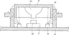
图3为图4在A-A位置的剖视图。Fig. 3 is a cross-sectional view at position A-A of Fig. 4 .
图4为本发明第一实施例背光型按键的发光元件配置示意图。FIG. 4 is a schematic diagram of the configuration of the light emitting elements of the backlight key according to the first embodiment of the present invention.
图5为本发明第一实施例背光型按键的发光元件另一配置示意图。FIG. 5 is a schematic diagram of another configuration of the light emitting elements of the backlight key according to the first embodiment of the present invention.
图6为本发明第二实施例背光型按键的剖视图。FIG. 6 is a cross-sectional view of a backlight key according to a second embodiment of the present invention.
图7为本发明第三实施例背光型按键的剖视图。FIG. 7 is a cross-sectional view of a backlight key according to a third embodiment of the present invention.
有关本发明的详细技术特征及其较佳实施例,现在就配合图式说明如下。The detailed technical features and preferred embodiments of the present invention are described below with reference to the accompanying drawings.
【具体实施方式】【Detailed ways】
请参阅图2,其中揭露了本发明的背光型按键总成30应用于一电子产品的电路板20的情形。Please refer to FIG. 2 , which discloses the application of the backlight key assembly 30 of the present invention to the
请参阅图3所示,本发明第一实施例的背光型按键总成30是包括一按键31、一导光元件40、以及至少一发光元件50;其中Please refer to FIG. 3, the backlight key assembly 30 of the first embodiment of the present invention includes a
按键31为不透光元件,配置在一切换开关(switch)32的上方,按键31的底端通常具有一突出部311,用以抵压并且触动切换开关32的压掣端321,按键31常态时通常被一些具有弹性的支撑元件如弹簧(图中未示)或是直接由切换开关32的压掣端321所支撑;The
导光元件40为透光元件,且其是围绕在按键31的周围,并且与按键31的轮廓形状配合但是不会影响按键31的运动,而本实施例中,导光元件40是一种环形的元件,并且站立或是固定在电路板20的表面,导光元件40为一种具导光性的元件,其可采用聚碳酸酯(polycarbonate;PC)或是压克力(acrylic,丙烯酸树酯)等透光的材料所制成,而其中聚碳酸酯的透光效果又较压克力为高;The
而发光元件50是安装在电路板20上,特别是在不透光的按键31的背面,并且被导光元件40所围绕,发光元件50可为不具方向性的发光二极管(LED)为最佳,由于发光元件50所射出的光线不具方向性,所以部分光线会直接地照射至导光元件40,而另一部分光线则会被不透光的按键31反射后再回来然后进入导光元件40,借助导光元件40的导光能力而将光线朝向按键31的前方引导透出,因此,可使光线均匀地分布于导光元件40以达到光线均匀化的目的,还可以避免局部亮点的出现。而发光元件50的配置是以按键31的中心点为中心的对称位置处设置较佳,例如:可于按键31的中心点的上方或下方各设置一个(如图4所示),或者可于按键31的中心点之四周各设置一个(如图5所示),发光元件50的配置数目可依背光型按键其背光光源亮度的需求增减。The light-emitting
前述的切换开关32是设置于按键31的下方,而切换开关32的实施例有多种,例如一种传统的切换开关是由一键帽、一弹性元件以及一薄膜电路所构成,弹性元件连接于键帽的下方,另弹性元件具有一突出部,且与薄膜电路之间形成一个空间,薄膜电路又分为第一导电部和第二导电部,中间亦有一空间使其于平常状态下不接触,借助按压键帽时,弹性元件的突出部则接触下方的薄膜电路而使得第一导电部和第二导电部接触,电路因而接通;另已公告的中国台湾第I223295号专利揭露了一种可节省空间及成本的按键开关,其是将第一导电部设置于弹性元件上,而第二导电部则位于薄膜电路上,借助按压键帽时,第一导电部和第二导电部就会接触而通电。而以上所揭露者仅为有关切换开关的补充说明,并非本发明的技术特征,举凡熟习此一技艺的人士皆可了解并且灵活运用。The
第一导电部和第二导电部请参阅图6所示,是揭露本发明第二实施例的背光型按键总成,其是采用了一种具有方向性的发光元件50a,并配合导光元件的形状以及发光元件50a的配置位置的改变,来达到前述的目的。本实施例中,导光元件40a为一截面具有至少一转折41的L型透光结构,L型透光结构的两端分别为入光端面42及出光端面43,出光端面43位于按键31周围,入光端面42是邻近电路板20设置并垂直于电路板20表面,而发光元件50a是设于入光端面42前,且发光元件50a的光线射出方向(图中箭头B所指的方向)是与电路板20的表面平行,以使发光元件50a射出的光线直接由入光端面42入射于导光元件40a内,而导光元件40a的转折41处具有一反射面,用以将来自于入光端面42的光线反射而朝向出光端面43(即按键31的前方)引导透出;借助具有转折的导光元件40a设置,使由发光元件50a射出的光线可透过转折41处弯折光线后再透出,故发光元件50a不会直射使用者,且透过导光元件40a的传递可使发光元件50a发出的光更均匀地透出。Please refer to FIG. 6 for the first conductive part and the second conductive part, which discloses the backlight key assembly of the second embodiment of the present invention, which adopts a directional light-emitting
请参阅图7所示,是揭露本发明第三实施例的背光型按键总成,本实施例与第二实施例不同之处在于,导光元件40b具有两个转折41a、41b,且转折41a、41b处形成有反射面,发光元件50a是直立于电路板20的表面,并位于入光端面42a下方,发光元件50a向上发出的光线,由入光端面42a进入导光元件40b,经转折41a及41b处进行两次反射后将光束弯折往出光端面43a射出,藉以提供按键31所需的均匀光线。Please refer to FIG. 7, which discloses the backlight key assembly of the third embodiment of the present invention. The difference between this embodiment and the second embodiment is that the light guide element 40b has two turning points 41a, 41b, and the turning point 41a , 41b is formed with a reflective surface, the light-emitting
综上所述,本发明是将按键采不透光的设计,再于按键的周围设置一导光元件,而发光元件是配置于由按键外部无法直视发光元件的位置,例如:按键的背面或设于导光元件的出光端面的侧边,以避免使用者直视发光元件及避免造成光点集中或是不均匀的现象,而发光元件所发出的光线再透过直射或是反射的路径被投射至围绕在按键周围的导光元件,借助导光元件的导光能力而将光线均匀化并朝向按键的前方引导透出,因此,可使光线均匀地分布于导光元件以达到光线均匀化的目的,并且避免局部亮点的出现。To sum up, the present invention adopts an opaque design for the key, and then sets a light guide element around the key, and the light-emitting element is arranged at a position where the light-emitting element cannot be directly seen from the outside of the key, for example: the back of the key Or set it on the side of the light-emitting end surface of the light-guiding element to prevent the user from looking directly at the light-emitting element and avoid the phenomenon of concentrated or uneven light spots, and the light emitted by the light-emitting element passes through the direct or reflected path It is projected to the light guide element surrounding the key, and the light is uniformized and directed toward the front of the key through the light guide ability of the light guide element. Therefore, the light can be evenly distributed in the light guide element to achieve light uniformity The purpose of optimization, and to avoid the appearance of local bright spots.
本发明虽以较佳实施例说明如上,然其并非用以限定本发明的保护范围,任何熟习此技术人员,在不脱离本发明的范围内所作变化,仍应属本发明的保护范围。Although the present invention has been described above with preferred embodiments, it is not intended to limit the protection scope of the present invention. Any changes made by those skilled in the art without departing from the scope of the present invention should still belong to the protection scope of the present invention.
Claims (16)
Priority Applications (1)
| Application Number | Priority Date | Filing Date | Title |
|---|---|---|---|
| CN 200510067491CN1855332A (en) | 2005-04-26 | 2005-04-26 | Backlit key assembly |
Applications Claiming Priority (1)
| Application Number | Priority Date | Filing Date | Title |
|---|---|---|---|
| CN 200510067491CN1855332A (en) | 2005-04-26 | 2005-04-26 | Backlit key assembly |
Publications (1)
| Publication Number | Publication Date |
|---|---|
| CN1855332Atrue CN1855332A (en) | 2006-11-01 |
Family
ID=37195405
Family Applications (1)
| Application Number | Title | Priority Date | Filing Date |
|---|---|---|---|
| CN 200510067491PendingCN1855332A (en) | 2005-04-26 | 2005-04-26 | Backlit key assembly |
Country Status (1)
| Country | Link |
|---|---|
| CN (1) | CN1855332A (en) |
Cited By (30)
| Publication number | Priority date | Publication date | Assignee | Title |
|---|---|---|---|---|
| CN101728105A (en)* | 2008-10-10 | 2010-06-09 | 三星电子株式会社 | Back lighting apparatus for keypad assembly |
| US7786396B2 (en) | 2007-12-27 | 2010-08-31 | Byd Co. Ltd. | Key-press structure and a method for making the same |
| US8389883B2 (en) | 2007-12-27 | 2013-03-05 | Byd Co., Ltd. | Key-press structure and a method for making the same |
| CN106024464A (en)* | 2016-07-04 | 2016-10-12 | 宁波方太厨具有限公司 | Touch switch |
| US9704665B2 (en) | 2014-05-19 | 2017-07-11 | Apple Inc. | Backlit keyboard including reflective component |
| US9704670B2 (en) | 2013-09-30 | 2017-07-11 | Apple Inc. | Keycaps having reduced thickness |
| US9710069B2 (en) | 2012-10-30 | 2017-07-18 | Apple Inc. | Flexible printed circuit having flex tails upon which keyboard keycaps are coupled |
| US9715978B2 (en) | 2014-05-27 | 2017-07-25 | Apple Inc. | Low travel switch assembly |
| US9761389B2 (en) | 2012-10-30 | 2017-09-12 | Apple Inc. | Low-travel key mechanisms with butterfly hinges |
| US9779889B2 (en) | 2014-03-24 | 2017-10-03 | Apple Inc. | Scissor mechanism features for a keyboard |
| US9793066B1 (en) | 2014-01-31 | 2017-10-17 | Apple Inc. | Keyboard hinge mechanism |
| US9870880B2 (en) | 2014-09-30 | 2018-01-16 | Apple Inc. | Dome switch and switch housing for keyboard assembly |
| US9908310B2 (en) | 2013-07-10 | 2018-03-06 | Apple Inc. | Electronic device with a reduced friction surface |
| US9916945B2 (en) | 2012-10-30 | 2018-03-13 | Apple Inc. | Low-travel key mechanisms using butterfly hinges |
| US9927895B2 (en) | 2013-02-06 | 2018-03-27 | Apple Inc. | Input/output device with a dynamically adjustable appearance and function |
| US9934915B2 (en) | 2015-06-10 | 2018-04-03 | Apple Inc. | Reduced layer keyboard stack-up |
| US9971084B2 (en) | 2015-09-28 | 2018-05-15 | Apple Inc. | Illumination structure for uniform illumination of keys |
| US9997308B2 (en) | 2015-05-13 | 2018-06-12 | Apple Inc. | Low-travel key mechanism for an input device |
| US9997304B2 (en) | 2015-05-13 | 2018-06-12 | Apple Inc. | Uniform illumination of keys |
| US10002727B2 (en) | 2013-09-30 | 2018-06-19 | Apple Inc. | Keycaps with reduced thickness |
| US10083805B2 (en) | 2015-05-13 | 2018-09-25 | Apple Inc. | Keyboard for electronic device |
| US10082880B1 (en) | 2014-08-28 | 2018-09-25 | Apple Inc. | System level features of a keyboard |
| US10115544B2 (en) | 2016-08-08 | 2018-10-30 | Apple Inc. | Singulated keyboard assemblies and methods for assembling a keyboard |
| US10128064B2 (en) | 2015-05-13 | 2018-11-13 | Apple Inc. | Keyboard assemblies having reduced thicknesses and method of forming keyboard assemblies |
| US10262814B2 (en) | 2013-05-27 | 2019-04-16 | Apple Inc. | Low travel switch assembly |
| US10353485B1 (en) | 2016-07-27 | 2019-07-16 | Apple Inc. | Multifunction input device with an embedded capacitive sensing layer |
| US10755877B1 (en) | 2016-08-29 | 2020-08-25 | Apple Inc. | Keyboard for an electronic device |
| US10775850B2 (en) | 2017-07-26 | 2020-09-15 | Apple Inc. | Computer with keyboard |
| US10796863B2 (en) | 2014-08-15 | 2020-10-06 | Apple Inc. | Fabric keyboard |
| US11500538B2 (en) | 2016-09-13 | 2022-11-15 | Apple Inc. | Keyless keyboard with force sensing and haptic feedback |
- 2005
- 2005-04-26CNCN 200510067491patent/CN1855332A/enactivePending
Cited By (47)
| Publication number | Priority date | Publication date | Assignee | Title |
|---|---|---|---|---|
| US7786396B2 (en) | 2007-12-27 | 2010-08-31 | Byd Co. Ltd. | Key-press structure and a method for making the same |
| US8389883B2 (en) | 2007-12-27 | 2013-03-05 | Byd Co., Ltd. | Key-press structure and a method for making the same |
| CN101728105A (en)* | 2008-10-10 | 2010-06-09 | 三星电子株式会社 | Back lighting apparatus for keypad assembly |
| US9710069B2 (en) | 2012-10-30 | 2017-07-18 | Apple Inc. | Flexible printed circuit having flex tails upon which keyboard keycaps are coupled |
| US11023081B2 (en) | 2012-10-30 | 2021-06-01 | Apple Inc. | Multi-functional keyboard assemblies |
| US9761389B2 (en) | 2012-10-30 | 2017-09-12 | Apple Inc. | Low-travel key mechanisms with butterfly hinges |
| US10699856B2 (en) | 2012-10-30 | 2020-06-30 | Apple Inc. | Low-travel key mechanisms using butterfly hinges |
| US10254851B2 (en) | 2012-10-30 | 2019-04-09 | Apple Inc. | Keyboard key employing a capacitive sensor and dome |
| US10211008B2 (en) | 2012-10-30 | 2019-02-19 | Apple Inc. | Low-travel key mechanisms using butterfly hinges |
| US9916945B2 (en) | 2012-10-30 | 2018-03-13 | Apple Inc. | Low-travel key mechanisms using butterfly hinges |
| US10114489B2 (en) | 2013-02-06 | 2018-10-30 | Apple Inc. | Input/output device with a dynamically adjustable appearance and function |
| US9927895B2 (en) | 2013-02-06 | 2018-03-27 | Apple Inc. | Input/output device with a dynamically adjustable appearance and function |
| US10262814B2 (en) | 2013-05-27 | 2019-04-16 | Apple Inc. | Low travel switch assembly |
| US10556408B2 (en) | 2013-07-10 | 2020-02-11 | Apple Inc. | Electronic device with a reduced friction surface |
| US9908310B2 (en) | 2013-07-10 | 2018-03-06 | Apple Inc. | Electronic device with a reduced friction surface |
| US9704670B2 (en) | 2013-09-30 | 2017-07-11 | Apple Inc. | Keycaps having reduced thickness |
| US10804051B2 (en) | 2013-09-30 | 2020-10-13 | Apple Inc. | Keycaps having reduced thickness |
| US10002727B2 (en) | 2013-09-30 | 2018-06-19 | Apple Inc. | Keycaps with reduced thickness |
| US10224157B2 (en) | 2013-09-30 | 2019-03-05 | Apple Inc. | Keycaps having reduced thickness |
| US11699558B2 (en) | 2013-09-30 | 2023-07-11 | Apple Inc. | Keycaps having reduced thickness |
| US9793066B1 (en) | 2014-01-31 | 2017-10-17 | Apple Inc. | Keyboard hinge mechanism |
| US9779889B2 (en) | 2014-03-24 | 2017-10-03 | Apple Inc. | Scissor mechanism features for a keyboard |
| US9704665B2 (en) | 2014-05-19 | 2017-07-11 | Apple Inc. | Backlit keyboard including reflective component |
| US9715978B2 (en) | 2014-05-27 | 2017-07-25 | Apple Inc. | Low travel switch assembly |
| US10796863B2 (en) | 2014-08-15 | 2020-10-06 | Apple Inc. | Fabric keyboard |
| US10082880B1 (en) | 2014-08-28 | 2018-09-25 | Apple Inc. | System level features of a keyboard |
| US10128061B2 (en) | 2014-09-30 | 2018-11-13 | Apple Inc. | Key and switch housing for keyboard assembly |
| US10134539B2 (en) | 2014-09-30 | 2018-11-20 | Apple Inc. | Venting system and shield for keyboard |
| US10192696B2 (en) | 2014-09-30 | 2019-01-29 | Apple Inc. | Light-emitting assembly for keyboard |
| US9870880B2 (en) | 2014-09-30 | 2018-01-16 | Apple Inc. | Dome switch and switch housing for keyboard assembly |
| US10083806B2 (en) | 2015-05-13 | 2018-09-25 | Apple Inc. | Keyboard for electronic device |
| US10083805B2 (en) | 2015-05-13 | 2018-09-25 | Apple Inc. | Keyboard for electronic device |
| US10128064B2 (en) | 2015-05-13 | 2018-11-13 | Apple Inc. | Keyboard assemblies having reduced thicknesses and method of forming keyboard assemblies |
| US9997308B2 (en) | 2015-05-13 | 2018-06-12 | Apple Inc. | Low-travel key mechanism for an input device |
| US9997304B2 (en) | 2015-05-13 | 2018-06-12 | Apple Inc. | Uniform illumination of keys |
| US10424446B2 (en) | 2015-05-13 | 2019-09-24 | Apple Inc. | Keyboard assemblies having reduced thickness and method of forming keyboard assemblies |
| US10468211B2 (en) | 2015-05-13 | 2019-11-05 | Apple Inc. | Illuminated low-travel key mechanism for a keyboard |
| US9934915B2 (en) | 2015-06-10 | 2018-04-03 | Apple Inc. | Reduced layer keyboard stack-up |
| US10310167B2 (en) | 2015-09-28 | 2019-06-04 | Apple Inc. | Illumination structure for uniform illumination of keys |
| US9971084B2 (en) | 2015-09-28 | 2018-05-15 | Apple Inc. | Illumination structure for uniform illumination of keys |
| CN106024464A (en)* | 2016-07-04 | 2016-10-12 | 宁波方太厨具有限公司 | Touch switch |
| US10353485B1 (en) | 2016-07-27 | 2019-07-16 | Apple Inc. | Multifunction input device with an embedded capacitive sensing layer |
| US10115544B2 (en) | 2016-08-08 | 2018-10-30 | Apple Inc. | Singulated keyboard assemblies and methods for assembling a keyboard |
| US11282659B2 (en) | 2016-08-08 | 2022-03-22 | Apple Inc. | Singulated keyboard assemblies and methods for assembling a keyboard |
| US10755877B1 (en) | 2016-08-29 | 2020-08-25 | Apple Inc. | Keyboard for an electronic device |
| US11500538B2 (en) | 2016-09-13 | 2022-11-15 | Apple Inc. | Keyless keyboard with force sensing and haptic feedback |
| US10775850B2 (en) | 2017-07-26 | 2020-09-15 | Apple Inc. | Computer with keyboard |
Similar Documents
| Publication | Publication Date | Title |
|---|---|---|
| CN1855332A (en) | Backlit key assembly | |
| US8592702B2 (en) | Illuminant keyboard device | |
| US7253369B2 (en) | Backlight button assemblage | |
| US8502094B2 (en) | Illuminated keyboard | |
| CN1897190A (en) | Key pad assembly for portable terminal | |
| CN101145458B (en) | Keyboards and Keyboard Components | |
| TWI539328B (en) | Luminous keyboard and light guide plate module thereof | |
| US8581125B2 (en) | Illuminated keyboard | |
| CN202258947U (en) | Luminous keyboard device | |
| US20180106956A1 (en) | Backlight module with membrane switch function | |
| TW201926392A (en) | Luminous keyboard | |
| CN204178989U (en) | Light-emitting structure around the keyboard backlight module | |
| CN100587878C (en) | Keyboard, keyboard assembly and portable terminal | |
| WO2019154321A1 (en) | Photosensitive component and mobile terminal | |
| TWI498773B (en) | Luminous keyboard | |
| TWI423289B (en) | Membrane circuit board and luminous keyboard using the same | |
| CN103985586A (en) | Luminous keyboard and light guide plate thereof | |
| US20130021297A1 (en) | Touch panel | |
| US20130093606A1 (en) | Illuminated keyboard | |
| US20240096567A1 (en) | Backlight module and backlight keyswitch thereof | |
| CN101315840B (en) | Movable contact element and switch using the same | |
| CN202307644U (en) | Keyboard apparatus having backlight module | |
| TWM544646U (en) | Thin luminescent keyboard and backlight module with membrane switch | |
| CN104252988A (en) | Illuminated keyboard device | |
| CN206471257U (en) | Backlight module with thin film switch function |
Legal Events
| Date | Code | Title | Description |
|---|---|---|---|
| C06 | Publication | ||
| PB01 | Publication | ||
| C10 | Entry into substantive examination | ||
| SE01 | Entry into force of request for substantive examination | ||
| C02 | Deemed withdrawal of patent application after publication (patent law 2001) | ||
| WD01 | Invention patent application deemed withdrawn after publication |