CN1845714A - Annulus repair systems, instruments and techniques - Google Patents
Annulus repair systems, instruments and techniquesDownload PDFInfo
- Publication number
- CN1845714A CN1845714ACNA2004800255876ACN200480025587ACN1845714ACN 1845714 ACN1845714 ACN 1845714ACN A2004800255876 ACNA2004800255876 ACN A2004800255876ACN 200480025587 ACN200480025587 ACN 200480025587ACN 1845714 ACN1845714 ACN 1845714A
- Authority
- CN
- China
- Prior art keywords
- closure elements
- anchor
- groove
- damaged
- hole
- Prior art date
- Legal status (The legal status is an assumption and is not a legal conclusion. Google has not performed a legal analysis and makes no representation as to the accuracy of the status listed.)
- Pending
Links
Images


Classifications
- A—HUMAN NECESSITIES
- A61—MEDICAL OR VETERINARY SCIENCE; HYGIENE
- A61B—DIAGNOSIS; SURGERY; IDENTIFICATION
- A61B17/00—Surgical instruments, devices or methods
- A61B17/56—Surgical instruments or methods for treatment of bones or joints; Devices specially adapted therefor
- A61B17/58—Surgical instruments or methods for treatment of bones or joints; Devices specially adapted therefor for osteosynthesis, e.g. bone plates, screws or setting implements
- A61B17/68—Internal fixation devices, including fasteners and spinal fixators, even if a part thereof projects from the skin
- A61B17/70—Spinal positioners or stabilisers, e.g. stabilisers comprising fluid filler in an implant
- A61B17/7001—Screws or hooks combined with longitudinal elements which do not contact vertebrae
- A61B17/7002—Longitudinal elements, e.g. rods
- A61B17/7004—Longitudinal elements, e.g. rods with a cross-section which varies along its length
- A61B17/7007—Parts of the longitudinal elements, e.g. their ends, being specially adapted to fit around the screw or hook heads
- A—HUMAN NECESSITIES
- A61—MEDICAL OR VETERINARY SCIENCE; HYGIENE
- A61B—DIAGNOSIS; SURGERY; IDENTIFICATION
- A61B17/00—Surgical instruments, devices or methods
- A61B17/14—Surgical saws
- A61B17/15—Guides therefor
- A—HUMAN NECESSITIES
- A61—MEDICAL OR VETERINARY SCIENCE; HYGIENE
- A61B—DIAGNOSIS; SURGERY; IDENTIFICATION
- A61B17/00—Surgical instruments, devices or methods
- A61B17/16—Instruments for performing osteoclasis; Drills or chisels for bones; Trepans
- A61B17/1662—Instruments for performing osteoclasis; Drills or chisels for bones; Trepans for particular parts of the body
- A61B17/1671—Instruments for performing osteoclasis; Drills or chisels for bones; Trepans for particular parts of the body for the spine
- A—HUMAN NECESSITIES
- A61—MEDICAL OR VETERINARY SCIENCE; HYGIENE
- A61B—DIAGNOSIS; SURGERY; IDENTIFICATION
- A61B17/00—Surgical instruments, devices or methods
- A61B17/16—Instruments for performing osteoclasis; Drills or chisels for bones; Trepans
- A61B17/17—Guides or aligning means for drills, mills, pins or wires
- A61B17/1739—Guides or aligning means for drills, mills, pins or wires specially adapted for particular parts of the body
- A61B17/1757—Guides or aligning means for drills, mills, pins or wires specially adapted for particular parts of the body for the spine
- A—HUMAN NECESSITIES
- A61—MEDICAL OR VETERINARY SCIENCE; HYGIENE
- A61F—FILTERS IMPLANTABLE INTO BLOOD VESSELS; PROSTHESES; DEVICES PROVIDING PATENCY TO, OR PREVENTING COLLAPSING OF, TUBULAR STRUCTURES OF THE BODY, e.g. STENTS; ORTHOPAEDIC, NURSING OR CONTRACEPTIVE DEVICES; FOMENTATION; TREATMENT OR PROTECTION OF EYES OR EARS; BANDAGES, DRESSINGS OR ABSORBENT PADS; FIRST-AID KITS
- A61F2/00—Filters implantable into blood vessels; Prostheses, i.e. artificial substitutes or replacements for parts of the body; Appliances for connecting them with the body; Devices providing patency to, or preventing collapsing of, tubular structures of the body, e.g. stents
- A61F2/02—Prostheses implantable into the body
- A61F2/30—Joints
- A61F2/44—Joints for the spine, e.g. vertebrae, spinal discs
- A61F2/442—Intervertebral or spinal discs, e.g. resilient
- A—HUMAN NECESSITIES
- A61—MEDICAL OR VETERINARY SCIENCE; HYGIENE
- A61F—FILTERS IMPLANTABLE INTO BLOOD VESSELS; PROSTHESES; DEVICES PROVIDING PATENCY TO, OR PREVENTING COLLAPSING OF, TUBULAR STRUCTURES OF THE BODY, e.g. STENTS; ORTHOPAEDIC, NURSING OR CONTRACEPTIVE DEVICES; FOMENTATION; TREATMENT OR PROTECTION OF EYES OR EARS; BANDAGES, DRESSINGS OR ABSORBENT PADS; FIRST-AID KITS
- A61F2/00—Filters implantable into blood vessels; Prostheses, i.e. artificial substitutes or replacements for parts of the body; Appliances for connecting them with the body; Devices providing patency to, or preventing collapsing of, tubular structures of the body, e.g. stents
- A61F2/02—Prostheses implantable into the body
- A61F2/28—Bones
- A—HUMAN NECESSITIES
- A61—MEDICAL OR VETERINARY SCIENCE; HYGIENE
- A61F—FILTERS IMPLANTABLE INTO BLOOD VESSELS; PROSTHESES; DEVICES PROVIDING PATENCY TO, OR PREVENTING COLLAPSING OF, TUBULAR STRUCTURES OF THE BODY, e.g. STENTS; ORTHOPAEDIC, NURSING OR CONTRACEPTIVE DEVICES; FOMENTATION; TREATMENT OR PROTECTION OF EYES OR EARS; BANDAGES, DRESSINGS OR ABSORBENT PADS; FIRST-AID KITS
- A61F2/00—Filters implantable into blood vessels; Prostheses, i.e. artificial substitutes or replacements for parts of the body; Appliances for connecting them with the body; Devices providing patency to, or preventing collapsing of, tubular structures of the body, e.g. stents
- A61F2/02—Prostheses implantable into the body
- A61F2/30—Joints
- A61F2/44—Joints for the spine, e.g. vertebrae, spinal discs
- A61F2/4455—Joints for the spine, e.g. vertebrae, spinal discs for the fusion of spinal bodies, e.g. intervertebral fusion of adjacent spinal bodies, e.g. fusion cages
- A—HUMAN NECESSITIES
- A61—MEDICAL OR VETERINARY SCIENCE; HYGIENE
- A61F—FILTERS IMPLANTABLE INTO BLOOD VESSELS; PROSTHESES; DEVICES PROVIDING PATENCY TO, OR PREVENTING COLLAPSING OF, TUBULAR STRUCTURES OF THE BODY, e.g. STENTS; ORTHOPAEDIC, NURSING OR CONTRACEPTIVE DEVICES; FOMENTATION; TREATMENT OR PROTECTION OF EYES OR EARS; BANDAGES, DRESSINGS OR ABSORBENT PADS; FIRST-AID KITS
- A61F2/00—Filters implantable into blood vessels; Prostheses, i.e. artificial substitutes or replacements for parts of the body; Appliances for connecting them with the body; Devices providing patency to, or preventing collapsing of, tubular structures of the body, e.g. stents
- A61F2/02—Prostheses implantable into the body
- A61F2/28—Bones
- A61F2002/2817—Bone stimulation by chemical reactions or by osteogenic or biological products for enhancing ossification, e.g. by bone morphogenetic or morphogenic proteins [BMP] or by transforming growth factors [TGF]
- A—HUMAN NECESSITIES
- A61—MEDICAL OR VETERINARY SCIENCE; HYGIENE
- A61F—FILTERS IMPLANTABLE INTO BLOOD VESSELS; PROSTHESES; DEVICES PROVIDING PATENCY TO, OR PREVENTING COLLAPSING OF, TUBULAR STRUCTURES OF THE BODY, e.g. STENTS; ORTHOPAEDIC, NURSING OR CONTRACEPTIVE DEVICES; FOMENTATION; TREATMENT OR PROTECTION OF EYES OR EARS; BANDAGES, DRESSINGS OR ABSORBENT PADS; FIRST-AID KITS
- A61F2/00—Filters implantable into blood vessels; Prostheses, i.e. artificial substitutes or replacements for parts of the body; Appliances for connecting them with the body; Devices providing patency to, or preventing collapsing of, tubular structures of the body, e.g. stents
- A61F2/02—Prostheses implantable into the body
- A61F2/30—Joints
- A61F2002/30001—Additional features of subject-matter classified in A61F2/28, A61F2/30 and subgroups thereof
- A61F2002/30003—Material related properties of the prosthesis or of a coating on the prosthesis
- A61F2002/3006—Properties of materials and coating materials
- A61F2002/30062—(bio)absorbable, biodegradable, bioerodable, (bio)resorbable, resorptive
- A—HUMAN NECESSITIES
- A61—MEDICAL OR VETERINARY SCIENCE; HYGIENE
- A61F—FILTERS IMPLANTABLE INTO BLOOD VESSELS; PROSTHESES; DEVICES PROVIDING PATENCY TO, OR PREVENTING COLLAPSING OF, TUBULAR STRUCTURES OF THE BODY, e.g. STENTS; ORTHOPAEDIC, NURSING OR CONTRACEPTIVE DEVICES; FOMENTATION; TREATMENT OR PROTECTION OF EYES OR EARS; BANDAGES, DRESSINGS OR ABSORBENT PADS; FIRST-AID KITS
- A61F2/00—Filters implantable into blood vessels; Prostheses, i.e. artificial substitutes or replacements for parts of the body; Appliances for connecting them with the body; Devices providing patency to, or preventing collapsing of, tubular structures of the body, e.g. stents
- A61F2/02—Prostheses implantable into the body
- A61F2/30—Joints
- A61F2002/30001—Additional features of subject-matter classified in A61F2/28, A61F2/30 and subgroups thereof
- A61F2002/30316—The prosthesis having different structural features at different locations within the same prosthesis; Connections between prosthetic parts; Special structural features of bone or joint prostheses not otherwise provided for
- A61F2002/30329—Connections or couplings between prosthetic parts, e.g. between modular parts; Connecting elements
- A61F2002/30433—Connections or couplings between prosthetic parts, e.g. between modular parts; Connecting elements using additional screws, bolts, dowels, rivets or washers e.g. connecting screws
- A—HUMAN NECESSITIES
- A61—MEDICAL OR VETERINARY SCIENCE; HYGIENE
- A61F—FILTERS IMPLANTABLE INTO BLOOD VESSELS; PROSTHESES; DEVICES PROVIDING PATENCY TO, OR PREVENTING COLLAPSING OF, TUBULAR STRUCTURES OF THE BODY, e.g. STENTS; ORTHOPAEDIC, NURSING OR CONTRACEPTIVE DEVICES; FOMENTATION; TREATMENT OR PROTECTION OF EYES OR EARS; BANDAGES, DRESSINGS OR ABSORBENT PADS; FIRST-AID KITS
- A61F2/00—Filters implantable into blood vessels; Prostheses, i.e. artificial substitutes or replacements for parts of the body; Appliances for connecting them with the body; Devices providing patency to, or preventing collapsing of, tubular structures of the body, e.g. stents
- A61F2/02—Prostheses implantable into the body
- A61F2/30—Joints
- A61F2002/30001—Additional features of subject-matter classified in A61F2/28, A61F2/30 and subgroups thereof
- A61F2002/30316—The prosthesis having different structural features at different locations within the same prosthesis; Connections between prosthetic parts; Special structural features of bone or joint prostheses not otherwise provided for
- A61F2002/30329—Connections or couplings between prosthetic parts, e.g. between modular parts; Connecting elements
- A61F2002/30448—Connections or couplings between prosthetic parts, e.g. between modular parts; Connecting elements using adhesives
- A—HUMAN NECESSITIES
- A61—MEDICAL OR VETERINARY SCIENCE; HYGIENE
- A61F—FILTERS IMPLANTABLE INTO BLOOD VESSELS; PROSTHESES; DEVICES PROVIDING PATENCY TO, OR PREVENTING COLLAPSING OF, TUBULAR STRUCTURES OF THE BODY, e.g. STENTS; ORTHOPAEDIC, NURSING OR CONTRACEPTIVE DEVICES; FOMENTATION; TREATMENT OR PROTECTION OF EYES OR EARS; BANDAGES, DRESSINGS OR ABSORBENT PADS; FIRST-AID KITS
- A61F2/00—Filters implantable into blood vessels; Prostheses, i.e. artificial substitutes or replacements for parts of the body; Appliances for connecting them with the body; Devices providing patency to, or preventing collapsing of, tubular structures of the body, e.g. stents
- A61F2/02—Prostheses implantable into the body
- A61F2/30—Joints
- A61F2002/30001—Additional features of subject-matter classified in A61F2/28, A61F2/30 and subgroups thereof
- A61F2002/30316—The prosthesis having different structural features at different locations within the same prosthesis; Connections between prosthetic parts; Special structural features of bone or joint prostheses not otherwise provided for
- A61F2002/30329—Connections or couplings between prosthetic parts, e.g. between modular parts; Connecting elements
- A61F2002/30451—Connections or couplings between prosthetic parts, e.g. between modular parts; Connecting elements soldered or brazed or welded
- A—HUMAN NECESSITIES
- A61—MEDICAL OR VETERINARY SCIENCE; HYGIENE
- A61F—FILTERS IMPLANTABLE INTO BLOOD VESSELS; PROSTHESES; DEVICES PROVIDING PATENCY TO, OR PREVENTING COLLAPSING OF, TUBULAR STRUCTURES OF THE BODY, e.g. STENTS; ORTHOPAEDIC, NURSING OR CONTRACEPTIVE DEVICES; FOMENTATION; TREATMENT OR PROTECTION OF EYES OR EARS; BANDAGES, DRESSINGS OR ABSORBENT PADS; FIRST-AID KITS
- A61F2/00—Filters implantable into blood vessels; Prostheses, i.e. artificial substitutes or replacements for parts of the body; Appliances for connecting them with the body; Devices providing patency to, or preventing collapsing of, tubular structures of the body, e.g. stents
- A61F2/02—Prostheses implantable into the body
- A61F2/30—Joints
- A61F2002/30001—Additional features of subject-matter classified in A61F2/28, A61F2/30 and subgroups thereof
- A61F2002/30316—The prosthesis having different structural features at different locations within the same prosthesis; Connections between prosthetic parts; Special structural features of bone or joint prostheses not otherwise provided for
- A61F2002/30329—Connections or couplings between prosthetic parts, e.g. between modular parts; Connecting elements
- A61F2002/30459—Connections or couplings between prosthetic parts, e.g. between modular parts; Connecting elements stapled
- A—HUMAN NECESSITIES
- A61—MEDICAL OR VETERINARY SCIENCE; HYGIENE
- A61F—FILTERS IMPLANTABLE INTO BLOOD VESSELS; PROSTHESES; DEVICES PROVIDING PATENCY TO, OR PREVENTING COLLAPSING OF, TUBULAR STRUCTURES OF THE BODY, e.g. STENTS; ORTHOPAEDIC, NURSING OR CONTRACEPTIVE DEVICES; FOMENTATION; TREATMENT OR PROTECTION OF EYES OR EARS; BANDAGES, DRESSINGS OR ABSORBENT PADS; FIRST-AID KITS
- A61F2/00—Filters implantable into blood vessels; Prostheses, i.e. artificial substitutes or replacements for parts of the body; Appliances for connecting them with the body; Devices providing patency to, or preventing collapsing of, tubular structures of the body, e.g. stents
- A61F2/02—Prostheses implantable into the body
- A61F2/30—Joints
- A61F2002/30001—Additional features of subject-matter classified in A61F2/28, A61F2/30 and subgroups thereof
- A61F2002/30316—The prosthesis having different structural features at different locations within the same prosthesis; Connections between prosthetic parts; Special structural features of bone or joint prostheses not otherwise provided for
- A61F2002/30329—Connections or couplings between prosthetic parts, e.g. between modular parts; Connecting elements
- A61F2002/30461—Connections or couplings between prosthetic parts, e.g. between modular parts; Connecting elements sutured, ligatured or stitched
- A—HUMAN NECESSITIES
- A61—MEDICAL OR VETERINARY SCIENCE; HYGIENE
- A61F—FILTERS IMPLANTABLE INTO BLOOD VESSELS; PROSTHESES; DEVICES PROVIDING PATENCY TO, OR PREVENTING COLLAPSING OF, TUBULAR STRUCTURES OF THE BODY, e.g. STENTS; ORTHOPAEDIC, NURSING OR CONTRACEPTIVE DEVICES; FOMENTATION; TREATMENT OR PROTECTION OF EYES OR EARS; BANDAGES, DRESSINGS OR ABSORBENT PADS; FIRST-AID KITS
- A61F2/00—Filters implantable into blood vessels; Prostheses, i.e. artificial substitutes or replacements for parts of the body; Appliances for connecting them with the body; Devices providing patency to, or preventing collapsing of, tubular structures of the body, e.g. stents
- A61F2/02—Prostheses implantable into the body
- A61F2/30—Joints
- A61F2002/30001—Additional features of subject-matter classified in A61F2/28, A61F2/30 and subgroups thereof
- A61F2002/30316—The prosthesis having different structural features at different locations within the same prosthesis; Connections between prosthetic parts; Special structural features of bone or joint prostheses not otherwise provided for
- A61F2002/30535—Special structural features of bone or joint prostheses not otherwise provided for
- A61F2002/30576—Special structural features of bone or joint prostheses not otherwise provided for with extending fixation tabs
- A61F2002/30578—Special structural features of bone or joint prostheses not otherwise provided for with extending fixation tabs having apertures, e.g. for receiving fixation screws
- A—HUMAN NECESSITIES
- A61—MEDICAL OR VETERINARY SCIENCE; HYGIENE
- A61F—FILTERS IMPLANTABLE INTO BLOOD VESSELS; PROSTHESES; DEVICES PROVIDING PATENCY TO, OR PREVENTING COLLAPSING OF, TUBULAR STRUCTURES OF THE BODY, e.g. STENTS; ORTHOPAEDIC, NURSING OR CONTRACEPTIVE DEVICES; FOMENTATION; TREATMENT OR PROTECTION OF EYES OR EARS; BANDAGES, DRESSINGS OR ABSORBENT PADS; FIRST-AID KITS
- A61F2/00—Filters implantable into blood vessels; Prostheses, i.e. artificial substitutes or replacements for parts of the body; Appliances for connecting them with the body; Devices providing patency to, or preventing collapsing of, tubular structures of the body, e.g. stents
- A61F2/02—Prostheses implantable into the body
- A61F2/30—Joints
- A61F2/30767—Special external or bone-contacting surface, e.g. coating for improving bone ingrowth
- A61F2/30771—Special external or bone-contacting surface, e.g. coating for improving bone ingrowth applied in original prostheses, e.g. holes or grooves
- A61F2002/30878—Special external or bone-contacting surface, e.g. coating for improving bone ingrowth applied in original prostheses, e.g. holes or grooves with non-sharp protrusions, for instance contacting the bone for anchoring, e.g. keels, pegs, pins, posts, shanks, stems, struts
- A61F2002/30891—Plurality of protrusions
- A61F2002/30892—Plurality of protrusions parallel
- A—HUMAN NECESSITIES
- A61—MEDICAL OR VETERINARY SCIENCE; HYGIENE
- A61F—FILTERS IMPLANTABLE INTO BLOOD VESSELS; PROSTHESES; DEVICES PROVIDING PATENCY TO, OR PREVENTING COLLAPSING OF, TUBULAR STRUCTURES OF THE BODY, e.g. STENTS; ORTHOPAEDIC, NURSING OR CONTRACEPTIVE DEVICES; FOMENTATION; TREATMENT OR PROTECTION OF EYES OR EARS; BANDAGES, DRESSINGS OR ABSORBENT PADS; FIRST-AID KITS
- A61F2/00—Filters implantable into blood vessels; Prostheses, i.e. artificial substitutes or replacements for parts of the body; Appliances for connecting them with the body; Devices providing patency to, or preventing collapsing of, tubular structures of the body, e.g. stents
- A61F2/02—Prostheses implantable into the body
- A61F2/30—Joints
- A61F2/44—Joints for the spine, e.g. vertebrae, spinal discs
- A61F2/442—Intervertebral or spinal discs, e.g. resilient
- A61F2002/4435—Support means or repair of the natural disc wall, i.e. annulus, e.g. using plates, membranes or meshes
- A—HUMAN NECESSITIES
- A61—MEDICAL OR VETERINARY SCIENCE; HYGIENE
- A61F—FILTERS IMPLANTABLE INTO BLOOD VESSELS; PROSTHESES; DEVICES PROVIDING PATENCY TO, OR PREVENTING COLLAPSING OF, TUBULAR STRUCTURES OF THE BODY, e.g. STENTS; ORTHOPAEDIC, NURSING OR CONTRACEPTIVE DEVICES; FOMENTATION; TREATMENT OR PROTECTION OF EYES OR EARS; BANDAGES, DRESSINGS OR ABSORBENT PADS; FIRST-AID KITS
- A61F2/00—Filters implantable into blood vessels; Prostheses, i.e. artificial substitutes or replacements for parts of the body; Appliances for connecting them with the body; Devices providing patency to, or preventing collapsing of, tubular structures of the body, e.g. stents
- A61F2/02—Prostheses implantable into the body
- A61F2/30—Joints
- A61F2/44—Joints for the spine, e.g. vertebrae, spinal discs
- A61F2/442—Intervertebral or spinal discs, e.g. resilient
- A61F2002/444—Intervertebral or spinal discs, e.g. resilient for replacing the nucleus pulposus
- A—HUMAN NECESSITIES
- A61—MEDICAL OR VETERINARY SCIENCE; HYGIENE
- A61F—FILTERS IMPLANTABLE INTO BLOOD VESSELS; PROSTHESES; DEVICES PROVIDING PATENCY TO, OR PREVENTING COLLAPSING OF, TUBULAR STRUCTURES OF THE BODY, e.g. STENTS; ORTHOPAEDIC, NURSING OR CONTRACEPTIVE DEVICES; FOMENTATION; TREATMENT OR PROTECTION OF EYES OR EARS; BANDAGES, DRESSINGS OR ABSORBENT PADS; FIRST-AID KITS
- A61F2210/00—Particular material properties of prostheses classified in groups A61F2/00 - A61F2/26 or A61F2/82 or A61F9/00 or A61F11/00 or subgroups thereof
- A61F2210/0004—Particular material properties of prostheses classified in groups A61F2/00 - A61F2/26 or A61F2/82 or A61F9/00 or A61F11/00 or subgroups thereof bioabsorbable
- A—HUMAN NECESSITIES
- A61—MEDICAL OR VETERINARY SCIENCE; HYGIENE
- A61F—FILTERS IMPLANTABLE INTO BLOOD VESSELS; PROSTHESES; DEVICES PROVIDING PATENCY TO, OR PREVENTING COLLAPSING OF, TUBULAR STRUCTURES OF THE BODY, e.g. STENTS; ORTHOPAEDIC, NURSING OR CONTRACEPTIVE DEVICES; FOMENTATION; TREATMENT OR PROTECTION OF EYES OR EARS; BANDAGES, DRESSINGS OR ABSORBENT PADS; FIRST-AID KITS
- A61F2220/00—Fixations or connections for prostheses classified in groups A61F2/00 - A61F2/26 or A61F2/82 or A61F9/00 or A61F11/00 or subgroups thereof
- A61F2220/0025—Connections or couplings between prosthetic parts, e.g. between modular parts; Connecting elements
- A61F2220/0041—Connections or couplings between prosthetic parts, e.g. between modular parts; Connecting elements using additional screws, bolts, dowels or rivets, e.g. connecting screws
- A—HUMAN NECESSITIES
- A61—MEDICAL OR VETERINARY SCIENCE; HYGIENE
- A61F—FILTERS IMPLANTABLE INTO BLOOD VESSELS; PROSTHESES; DEVICES PROVIDING PATENCY TO, OR PREVENTING COLLAPSING OF, TUBULAR STRUCTURES OF THE BODY, e.g. STENTS; ORTHOPAEDIC, NURSING OR CONTRACEPTIVE DEVICES; FOMENTATION; TREATMENT OR PROTECTION OF EYES OR EARS; BANDAGES, DRESSINGS OR ABSORBENT PADS; FIRST-AID KITS
- A61F2220/00—Fixations or connections for prostheses classified in groups A61F2/00 - A61F2/26 or A61F2/82 or A61F9/00 or A61F11/00 or subgroups thereof
- A61F2220/0025—Connections or couplings between prosthetic parts, e.g. between modular parts; Connecting elements
- A61F2220/005—Connections or couplings between prosthetic parts, e.g. between modular parts; Connecting elements using adhesives
- A—HUMAN NECESSITIES
- A61—MEDICAL OR VETERINARY SCIENCE; HYGIENE
- A61F—FILTERS IMPLANTABLE INTO BLOOD VESSELS; PROSTHESES; DEVICES PROVIDING PATENCY TO, OR PREVENTING COLLAPSING OF, TUBULAR STRUCTURES OF THE BODY, e.g. STENTS; ORTHOPAEDIC, NURSING OR CONTRACEPTIVE DEVICES; FOMENTATION; TREATMENT OR PROTECTION OF EYES OR EARS; BANDAGES, DRESSINGS OR ABSORBENT PADS; FIRST-AID KITS
- A61F2220/00—Fixations or connections for prostheses classified in groups A61F2/00 - A61F2/26 or A61F2/82 or A61F9/00 or A61F11/00 or subgroups thereof
- A61F2220/0025—Connections or couplings between prosthetic parts, e.g. between modular parts; Connecting elements
- A61F2220/0058—Connections or couplings between prosthetic parts, e.g. between modular parts; Connecting elements soldered or brazed or welded
- A—HUMAN NECESSITIES
- A61—MEDICAL OR VETERINARY SCIENCE; HYGIENE
- A61F—FILTERS IMPLANTABLE INTO BLOOD VESSELS; PROSTHESES; DEVICES PROVIDING PATENCY TO, OR PREVENTING COLLAPSING OF, TUBULAR STRUCTURES OF THE BODY, e.g. STENTS; ORTHOPAEDIC, NURSING OR CONTRACEPTIVE DEVICES; FOMENTATION; TREATMENT OR PROTECTION OF EYES OR EARS; BANDAGES, DRESSINGS OR ABSORBENT PADS; FIRST-AID KITS
- A61F2220/00—Fixations or connections for prostheses classified in groups A61F2/00 - A61F2/26 or A61F2/82 or A61F9/00 or A61F11/00 or subgroups thereof
- A61F2220/0025—Connections or couplings between prosthetic parts, e.g. between modular parts; Connecting elements
- A61F2220/0066—Connections or couplings between prosthetic parts, e.g. between modular parts; Connecting elements stapled
- A—HUMAN NECESSITIES
- A61—MEDICAL OR VETERINARY SCIENCE; HYGIENE
- A61F—FILTERS IMPLANTABLE INTO BLOOD VESSELS; PROSTHESES; DEVICES PROVIDING PATENCY TO, OR PREVENTING COLLAPSING OF, TUBULAR STRUCTURES OF THE BODY, e.g. STENTS; ORTHOPAEDIC, NURSING OR CONTRACEPTIVE DEVICES; FOMENTATION; TREATMENT OR PROTECTION OF EYES OR EARS; BANDAGES, DRESSINGS OR ABSORBENT PADS; FIRST-AID KITS
- A61F2220/00—Fixations or connections for prostheses classified in groups A61F2/00 - A61F2/26 or A61F2/82 or A61F9/00 or A61F11/00 or subgroups thereof
- A61F2220/0025—Connections or couplings between prosthetic parts, e.g. between modular parts; Connecting elements
- A61F2220/0075—Connections or couplings between prosthetic parts, e.g. between modular parts; Connecting elements sutured, ligatured or stitched, retained or tied with a rope, string, thread, wire or cable
- A—HUMAN NECESSITIES
- A61—MEDICAL OR VETERINARY SCIENCE; HYGIENE
- A61F—FILTERS IMPLANTABLE INTO BLOOD VESSELS; PROSTHESES; DEVICES PROVIDING PATENCY TO, OR PREVENTING COLLAPSING OF, TUBULAR STRUCTURES OF THE BODY, e.g. STENTS; ORTHOPAEDIC, NURSING OR CONTRACEPTIVE DEVICES; FOMENTATION; TREATMENT OR PROTECTION OF EYES OR EARS; BANDAGES, DRESSINGS OR ABSORBENT PADS; FIRST-AID KITS
- A61F2310/00—Prostheses classified in A61F2/28 or A61F2/30 - A61F2/44 being constructed from or coated with a particular material
- A61F2310/00005—The prosthesis being constructed from a particular material
- A61F2310/00179—Ceramics or ceramic-like structures
- A61F2310/00293—Ceramics or ceramic-like structures containing a phosphorus-containing compound, e.g. apatite
- A—HUMAN NECESSITIES
- A61—MEDICAL OR VETERINARY SCIENCE; HYGIENE
- A61F—FILTERS IMPLANTABLE INTO BLOOD VESSELS; PROSTHESES; DEVICES PROVIDING PATENCY TO, OR PREVENTING COLLAPSING OF, TUBULAR STRUCTURES OF THE BODY, e.g. STENTS; ORTHOPAEDIC, NURSING OR CONTRACEPTIVE DEVICES; FOMENTATION; TREATMENT OR PROTECTION OF EYES OR EARS; BANDAGES, DRESSINGS OR ABSORBENT PADS; FIRST-AID KITS
- A61F2310/00—Prostheses classified in A61F2/28 or A61F2/30 - A61F2/44 being constructed from or coated with a particular material
- A61F2310/00005—The prosthesis being constructed from a particular material
- A61F2310/00329—Glasses, e.g. bioglass
- A—HUMAN NECESSITIES
- A61—MEDICAL OR VETERINARY SCIENCE; HYGIENE
- A61F—FILTERS IMPLANTABLE INTO BLOOD VESSELS; PROSTHESES; DEVICES PROVIDING PATENCY TO, OR PREVENTING COLLAPSING OF, TUBULAR STRUCTURES OF THE BODY, e.g. STENTS; ORTHOPAEDIC, NURSING OR CONTRACEPTIVE DEVICES; FOMENTATION; TREATMENT OR PROTECTION OF EYES OR EARS; BANDAGES, DRESSINGS OR ABSORBENT PADS; FIRST-AID KITS
- A61F2310/00—Prostheses classified in A61F2/28 or A61F2/30 - A61F2/44 being constructed from or coated with a particular material
- A61F2310/00005—The prosthesis being constructed from a particular material
- A61F2310/00359—Bone or bony tissue
- A—HUMAN NECESSITIES
- A61—MEDICAL OR VETERINARY SCIENCE; HYGIENE
- A61F—FILTERS IMPLANTABLE INTO BLOOD VESSELS; PROSTHESES; DEVICES PROVIDING PATENCY TO, OR PREVENTING COLLAPSING OF, TUBULAR STRUCTURES OF THE BODY, e.g. STENTS; ORTHOPAEDIC, NURSING OR CONTRACEPTIVE DEVICES; FOMENTATION; TREATMENT OR PROTECTION OF EYES OR EARS; BANDAGES, DRESSINGS OR ABSORBENT PADS; FIRST-AID KITS
- A61F2310/00—Prostheses classified in A61F2/28 or A61F2/30 - A61F2/44 being constructed from or coated with a particular material
- A61F2310/00005—The prosthesis being constructed from a particular material
- A61F2310/00365—Proteins; Polypeptides; Degradation products thereof
Landscapes
- Health & Medical Sciences (AREA)
- Life Sciences & Earth Sciences (AREA)
- Orthopedic Medicine & Surgery (AREA)
- Surgery (AREA)
- Biomedical Technology (AREA)
- Engineering & Computer Science (AREA)
- Veterinary Medicine (AREA)
- Animal Behavior & Ethology (AREA)
- Public Health (AREA)
- Heart & Thoracic Surgery (AREA)
- General Health & Medical Sciences (AREA)
- Medical Informatics (AREA)
- Molecular Biology (AREA)
- Nuclear Medicine, Radiotherapy & Molecular Imaging (AREA)
- Oral & Maxillofacial Surgery (AREA)
- Neurology (AREA)
- Dentistry (AREA)
- Cardiology (AREA)
- Transplantation (AREA)
- Vascular Medicine (AREA)
- Prostheses (AREA)
- Surgical Instruments (AREA)
Abstract
Description
Translated fromChinese背景技术 Background technique
本发明一般涉及脊椎外科领域,更具体涉及用于修复环面缺损的系统和技术。The present invention relates generally to the field of spinal surgery, and more particularly to systems and techniques for repairing annulus defects.
各种外科过程和病症可导致纤维化环的缺损,例如环面切除术、椎间盘切除术、核切除术、人工盘核或人工盘假体的植入、盘疝出的修复和环面变性。通常认为修复环面缺损耗时且无效率。因此,一般不修复环面缺损。这可导致盘疝出或或再疝出、或植入物从盘间隙排出更高的发生率。Defects of the fibrotic annulus can result from various surgical procedures and conditions, such as toricectomy, discectomy, nucleectomy, implantation of an artificial disc nucleus or prosthetic disc, repair of disc herniation, and annulus degeneration. Repairing torus defects is generally considered time-consuming and inefficient. Therefore, annulus defects are generally not repaired. This can lead to a higher incidence of disc herniation or reherniation, or expulsion of the implant from the disc space.
在那些通过缝合修复环的过程中,试图通过将周围的组织牵拉到一起闭合缺损,遇到了困难。通常,环面缺损的洞较大,用常规缝合技术难以闭合。也难以使周围环面组织活性地掺入缝合,并且,修复后缝合可切割或撕拉环面组织。During those repairs of the ring with suturing, difficulty was encountered in attempting to close the defect by pulling the surrounding tissue together. Usually, the holes in annular defects are large and difficult to close with conventional suturing techniques. It is also difficult to actively incorporate sutures into the surrounding annulus tissue, and the sutures can cut or tear the annulus tissue after repair.
发明概述Summary of Invention
本发明涉及修复环面缺损的系统、装置、技术和方法。系统和装置的实施方式包括至少一个封闭元件,它位于环面缺损中或邻近环面缺损并结合相邻组织。还提供了用于结合环面缺损中和/或邻近处的组织元件以修复椎骨的器械。封闭元件至少部分延伸跨过环面缺损,用于修复缺损和/或保留核材料、一种或多种植入物、生物相容材料或装置和/或其它位于盘间隙的物质。The invention relates to a system, device, technique and method for repairing annulus defects. Embodiments of the systems and devices include at least one closure element located in or adjacent to the annulus defect and engaging adjacent tissue. Also provided are instruments for engaging tissue elements in and/or adjacent an annulus defect to repair a vertebra. The closure element extends at least partially across the annular defect for repairing the defect and/or retaining nuclear material, one or more implants, biocompatible materials or devices, and/or other substances located in the interdiscal space.
附图简述Brief description of attached drawings
图1是一个实施方式的环面修复装置的正视图。Fig. 1 is a front view of an annulus repair device according to one embodiment.
图2是一个实施方式的紧固件对的正视图,该紧固件用于将图1所示装置固定于相邻椎骨。Figure 2 is an elevational view of an embodiment of a pair of fasteners for securing the device of Figure 1 to adjacent vertebrae.
图3是具有环面缺损的脊柱区段的正视图。Figure 3 is an elevational view of a spinal column segment with an annular defect.
图4是通过图3所示脊柱区段的缺损的截面图。FIG. 4 is a cross-sectional view through a defect of the spinal column segment shown in FIG. 3 .
图5是具有相邻椎骨中形成的洞的脊柱区段的正视图。5 is an elevational view of a spinal column segment with holes formed in adjacent vertebrae.
图6是通过图5所示脊柱区段的缺损的截面图。FIG. 6 is a cross-sectional view through a defect of the spinal column segment shown in FIG. 5 .
图7是具有与洞接触的相邻椎骨中形成的凹槽的脊椎区段的正式图。Figure 7 is a canonical view of a vertebral segment with grooves formed in adjacent vertebrae in contact with holes.
图8是通过图7所示脊柱区段的缺损的截面图。FIG. 8 is a cross-sectional view through the defect of the spinal column segment shown in FIG. 7 .
图9是具有图1所示修复装置固定在洞和相邻椎骨中形成的凹槽中的脊椎区段的正视图。9 is an elevational view of a vertebral segment with the prosthetic device shown in FIG. 1 secured in the hole and groove formed in the adjacent vertebrae.
图10是通过图9所示脊柱区段的缺损的截面图。FIG. 10 is a cross-sectional view through the defect of the spinal column segment shown in FIG. 9 .
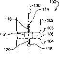
图11是另一个实施方式的环面修复装置的正视图。Fig. 11 is a front view of another embodiment of an annulus repair device.
图12是另一个实施方式的紧固件对的正视图,用于将图11所示装置固定于相邻椎骨。12 is an elevational view of another embodiment of a pair of fasteners for securing the device of FIG. 11 to adjacent vertebrae.
图13是具有相邻椎骨中形成的洞的脊柱区段的正视图。Figure 13 is an elevational view of a spinal column segment with holes formed in adjacent vertebrae.
图14是通过图13所示脊柱区段的缺损的截面图。FIG. 14 is a cross-sectional view through a defect of the spinal column segment shown in FIG. 13 .
图15是具有与洞接触的相邻椎骨中形成的凹槽的脊椎区段的正式图。Figure 15 is a canonical view of a vertebral segment with grooves formed in adjacent vertebrae in contact with holes.
图16是通过图15所示脊柱区段的缺损的截面图。FIG. 16 is a cross-sectional view through the defect of the spinal column segment shown in FIG. 15 .
图17是具有图11所示修复装置固定在洞和相邻椎骨中形成的凹槽中的脊椎区段的正视图。17 is an elevational view of a vertebral segment with the prosthetic device shown in FIG. 11 secured in the hole and groove formed in the adjacent vertebrae.
图18是通过图17所示脊柱区段的缺损的截面图。FIG. 18 is a cross-sectional view through the defect of the spinal column segment shown in FIG. 17 .
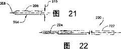
图19是一个实施方式的切割器械的正视图。Figure 19 is a front view of a cutting instrument of one embodiment.
图20是图19所示器械轴的远端部分的俯视图。20 is a top view of the distal portion of the instrument shaft shown in FIG. 19 .
图21包含图19所示器械的一部分的切割刀的远端部分的俯视图。FIG. 21 is a top view of a distal portion of a cutting blade comprising a portion of the instrument shown in FIG. 19 .
图22是钻孔器械的正视图。Figure 22 is a front view of the drilling instrument.
图23是一个实施方式的导向器械的透视图,与图19和22所示的切割器械和钻孔器械一起使用。23 is a perspective view of one embodiment of a guide instrument for use with the cutting and drilling instruments shown in FIGS. 19 and 22 .
图24是图23所示导向器械的远端部分的分解透视图。24 is an exploded perspective view of the distal portion of the guide instrument shown in FIG. 23. FIG.
具体实施方式 Detailed ways
为了促进对本发明原理的理解,现在将参考所述实施方式并用具体语言描述这些实施方式。应理解这些实施方式不是对本发明范围的限制。包括了实施方式的任何改变和进一步改进以及这里所述本发明原理的任何进一步应用,正如本发明所涉及领域的技术人员一般所理解的那样。In order to promote an understanding of the principles of the invention, reference will now be made to the embodiments and specific language will be used to describe the same. It should be understood that these embodiments do not limit the scope of the present invention. Any alterations and further improvements of the embodiments and any further applications of the principles of the invention described herein are contemplated as would generally be understood by one skilled in the art to which the invention pertains.
环面修复系统和方法包括保留在脊椎盘的纤维化环的缺损内或邻近该缺损的封闭元件。该封闭元件可封闭所有或部分缺损或纤维化环内的孔隙,例如可由外科或盘疝出导致的。封闭元件保留在对应于相邻的软组织或硬组织的缺损或孔隙内基本上固定的位置。封闭元件可包括一个或多个连接于封闭元件或与封闭元件整合形成的附着部分。该附着部分可与骨或邻近缺损或孔隙的其它组织啮合。Annulus repair systems and methods include a closure element that remains within or adjacent to a defect in the fibrotic annulus of a spinal disc. The closure element may close all or part of a defect or aperture within the fibrotic annulus, such as may result from surgery or disc herniation. The closure element remains in a substantially fixed position within the defect or aperture corresponding to adjacent soft or hard tissue. The closure element may include one or more attachment portions attached to or integrally formed with the closure element. The attachment portion can engage bone or other tissue adjacent to the defect or porosity.
参考本文所述各种实施方式,将封闭元件嵌入或放置于缺损内,使其基本上延伸跨过环面缺损。封闭元件的啮合放置有利于封闭元件向环内壁的放置,进而邻近核和/或位于盘间隙中的植入物。封闭元件可阻止植入物和/或核迁移进入环面缺损,提供有效的封闭机制并修复环面缺损。With reference to the various embodiments described herein, the closure element is embedded or placed within the defect such that it extends substantially across the annular defect. The engaged placement of the closure element facilitates placement of the closure element towards the inner wall of the annulus, thereby adjacent to the nucleus and/or the implant located in the disc space. The closure element prevents migration of the implant and/or nucleus into the annulus defect, provides an effective closure mechanism and repairs the annulus defect.
与封闭元件相连的附着部分和/或锚可与相邻的骨部分啮合,以促进封闭元件结合环面缺损内的部分。锚可直接使封闭元件结合于相邻组织。如果需要,使用各种装置和/或技术可使附着部分结合于或固定于封闭元件,或者附着部分可是与封闭元件整合形成的或是封闭元件的延伸。例如通过将附着部分缝合至封闭元件、热焊接或粘结、粘性粘结、三维织造或编织、螺钉、卡钉、销钉、平头钉、锯齿形或铆钉固定,封闭元件可连接于或结合于附着部分。而且,可在将封闭元件放置在环面缺损内之前或之后,将附着部分固定于封闭元件。还考虑可以(例如)以缝线、丝、缆或线的形式提供附着部分,插入封闭元件并将封闭元件固定于与邻近缺损的组织啮合的锚。Attachment portions and/or anchors associated with the closure element can engage adjacent bony portions to facilitate engagement of the closure element with portions within the annular defect. The anchor can directly bind the closure element to adjacent tissue. If desired, the attachment portion may be bonded or secured to the closure member using various devices and/or techniques, or the attachment portion may be integrally formed with or an extension of the closure member. The closure element may be attached or bonded to the attachment portion, for example by suturing the attachment portion to the closure element, heat welding or bonding, adhesive bonding, three-dimensional weaving or braiding, screws, staples, pins, tacks, zigzags, or rivets. part. Furthermore, the attachment portion may be secured to the closure element either before or after placement of the closure element within the annulus defect. It is also contemplated that the attachment portion may be provided, eg, in the form of a suture, wire, cable, or thread, through which the closure element is inserted and secured to an anchor that engages tissue adjacent the defect.
封闭元件可以是各种形式。封闭元件的例子包括缝线、系绳、筛网、片板、栓塞、支架或它们的组合。封闭元件可由柔性组件或显示至少部分柔性的组件构成。这种组件的例子包括织造织物管、织造或非织造筛网、或编织或织造结构、折叠织造织物、系绳、绳索、平面元件、带、线、缆或任何其它能够延伸跨过环面缺损的组件。另外,封闭元件可是反弹性和/或弹性的,使得在啮合和结合过程中或之后能保证各种形状。可将生长因子或细胞掺入封闭元件中以加速环面修复过程。生长因子可以是转化生长因子β1、胰岛素样生长因子1、血小板衍生生长因子、成纤维细胞生长因子、骨形态生成蛋白(BMP)、LIM矿化蛋白(LMP)以及它们的组合。The closure element can be in various forms. Examples of closure elements include sutures, tethers, screens, panels, plugs, stents, or combinations thereof. The closure element may consist of a flexible component or a component exhibiting at least partial flexibility. Examples of such components include woven fabric tubes, woven or nonwoven screens, or woven or woven structures, folded woven fabrics, tethers, cords, planar elements, straps, wires, cables, or any other components capable of extending across an annulus defect. s component. In addition, the closure element may be resilient and/or elastic such that various shapes are maintained during or after engagement and engagement. Growth factors or cells can be incorporated into the closure element to accelerate the annulus repair process. The growth factor may be transforming growth factor β1, insulin-like growth factor 1, platelet-derived growth factor, fibroblast growth factor, bone morphogenetic protein (BMP), LIM mineralization protein (LMP), and combinations thereof.
封闭元件可以由任何生物相容材料,合成或天然来源的材料以及再吸收性或非再吸收性材料构成。合适的封闭元件材料的例子包括自体植入物、同种异体植入物或异种植入物;组织材料包括软组织、结缔组织、去矿化骨基质以及人们的组合;再吸收性材料包括聚丙交酯、聚乙交酯、酪氨酸衍生的聚碳酸酯、聚酐、聚原酸酯、聚磷腈、磷酸钙、羟基磷灰石、生物活性玻璃、胶原、白蛋白、纤维蛋白原以及它们的组合;非再吸收性材料包括聚乙烯、聚酯、聚乙烯醇、聚丙烯腈、聚酰胺、聚四氟乙烯、聚对苯撑对苯二酸酰胺(polyparaphenyleneterephthalamide)、纤维素以及它们的组合。The closure element may be constructed of any biocompatible material, synthetic or natural in origin and resorbable or non-resorbable. Examples of suitable closure element materials include autologous, allograft, or xenograft implants; tissue materials include soft tissue, connective tissue, demineralized bone matrix, and human combinations; resorbable materials include polypropylene Esters, polyglycolides, tyrosine-derived polycarbonates, polyanhydrides, polyorthoesters, polyphosphazenes, calcium phosphate, hydroxyapatite, bioactive glass, collagen, albumin, fibrinogen, and their combinations; non-resorbable materials include polyethylene, polyester, polyvinyl alcohol, polyacrylonitrile, polyamide, polytetrafluoroethylene, polyparaphenyleneterephthalamide, cellulose, and combinations thereof .
锚可由任何生物相容材料构成,包括合成或天然的自体植入、同种异体植入物或异种植入组织,锚可以是再吸收性或非再吸收性的。组织材料的例子包括硬组织、结缔组织、去矿化骨基质以及它们的组合。再吸收性材料的例子还包括:聚丙交酯、聚乙交酯、酪氨酸衍生的聚碳酸酯、聚酐、聚原酸酯、聚磷腈、磷酸钙、羟基磷灰石、生物活性玻璃以及它们的组合。非再吸收性材料的例子还包括:高性能聚合物,例如聚醚醚酮、碳强化聚合复合物、形状记忆合金、钛、钛合金、钴铬合金、不锈钢,以及它们的组合。The anchor can be constructed of any biocompatible material, including synthetic or natural autologous, allograft, or xenograft tissue, and the anchor can be resorbable or non-resorbable. Examples of tissue materials include hard tissue, connective tissue, demineralized bone matrix, and combinations thereof. Examples of resorbable materials also include: polylactide, polyglycolide, tyrosine-derived polycarbonate, polyanhydrides, polyorthoesters, polyphosphazenes, calcium phosphate, hydroxyapatite, bioactive glass and their combinations. Examples of non-resorbable materials also include high performance polymers such as polyether ether ketone, carbon reinforced polymer composites, shape memory alloys, titanium, titanium alloys, cobalt chromium alloys, stainless steel, and combinations thereof.
锚可以是固体、多孔、半多孔、有孔、管状以及它们的组合,以在需要时提供强度和钴向内生长。锚的外表面可以是光滑的、粗糙的、多孔的、锯齿状的或是它们的组合,以提供所需拔拉阻力。锚可具有一个或多个组织锚拔出的可移动组件,例如翼、齿槽或弹性倒刺。还考虑锚可构造成通过旋转力、压缩力中的任何一种或其组合能够放入或插入组织的形状,锚与开口啮合然后扩张进入周围组织,例如,粘合或粘结、融合且组织向内生长。锚可以是各种形状,包括螺钉、平头钉、销钉、卡钉、缝合锚和楔。Anchors can be solid, porous, semi-porous, porous, tubular, and combinations thereof to provide strength and cobalt ingrowth when needed. The outer surface of the anchor can be smooth, rough, porous, serrated or a combination thereof to provide the desired pull-out resistance. The anchor may have one or more movable components for tissue anchor extraction, such as wings, gullets, or resilient barbs. It is also contemplated that the anchor can be configured into a shape that can be placed or inserted into the tissue by any one of rotational force, compressive force, or a combination thereof, the anchor engages the opening and then expands into the surrounding tissue, e.g., bonds or bonds, fuses and the tissue Ingrown. Anchors can be in various shapes, including screws, tacks, pins, staples, suture anchors, and wedges.
参考图1和2,显示了根据一个实施方式的环面修复系统。该环面修复系统包括封闭元件50和一对锚70,80以将封闭元件50固定于患者的组织。封闭元件50包括延伸在第一末端54和相对的第二末端56之间的主体52。封闭元件50在第一末端54和第二末端56之间的长度足以跨越封闭元件50所结合的组织结构间的环面缺损。主体52的宽度68足以延伸跨过至少一部分环面缺损图提供一个有效的机械屏障。在一个实施方式中,宽度68延伸跨过至少10%的环面缺损宽度。在另一个实施方式中,宽度68延伸跨过至少50%的环面缺损。在另一个实施方式中,主体52的宽度68的范围约为环面缺损宽度的10%-50%。在又一个实施方式中,宽度68延伸跨过基本上整个环面缺损的宽度。在再一个实施方式中,主体52的宽度68大于环面缺损的宽度,主体52被侧向压制以配合环面缺损。Referring to Figures 1 and 2, an annulus repair system according to one embodiment is shown. The annulus repair system includes a
第一末端54包括附着部分58,通道60穿过其中以接受锚70。第二末端56包括附着部分62,通道64穿过其中以接受锚80。锚70可具有近端部分72和远端啮合部分74。类似地,锚80可具有近端部分82和远端啮合部分84。所示锚70,80是骨螺钉形式,在近端部分72,82处具有扩大的头部和带螺纹的远端啮合部分74,84。当放置通过相应的通道60,64时,近端部分72,82各包括配合各自附着部分58,62的放大的头部,以将封闭元件50固定于锚70,80所啮合的组织。The first end 54 includes an
在一个具体实施方式中,附着部分是圆形眼孔形式,由合适的生物相容金属或聚合材料构成,并提供配合锚70,80近端部分72,82的刚性主体。在一种形式中,附着部分可以是球形围绕圆形通道60,64为中心的,以配合锚70,80头部的球形表面,使锚70,80相对于附着部分58,62呈多轴角取向。在另一种形式中,附着部分58,62的构型能与锚70,80啮合以提供锚70,80贯穿其中的固定取向。还考虑一个附着部分58,62及其相应的锚70,80能使锚的放置为可变角,而另一个附着部分58,62及锚70,80使锚的放置为固定角。In one embodiment, the attachment portion is in the form of a circular eyelet constructed of a suitable biocompatible metal or polymeric material and provides a rigid body to which the proximal portion 72,82 of the
锚70,80可包括近端部分72,82近端处的工具啮合开口,以促进旋转驱动力的应用,例如螺丝刀。其它实施方式考虑了上述锚70,80的其它形式,包括用压制力或线性驱动使锚进入骨组织。还考虑锚70,80可与各自的附着部分58,62整合。在又一种形式中,考虑附着部分58,62没有通道,锚70,80穿过附着部分58,62。在再一种形式中,锚70,80穿过主体52,使封闭元件50与相邻组织啮合。
现在再参考图3和4,脊柱区段100包括第一椎骨102、第二椎骨104和它们之间的脊柱盘间隙106。脊柱盘间隙106包括延伸在其周围的环面108。环面108包括在其中形成的缺损110。缺损110可以是以下任何一种或几种原因的组合导致或形成的,包括环面切除术、椎间盘切除术、核切除术、人工盘核或人工盘假体的植入、盘疝出的修复、或环面相关的裂痕、撕拉或其它变性或病症。考虑可将环面修复系统放置在缺损中椎骨102,104的任何位置,包括椎骨102,104的前端、前侧部、侧面、后端、后侧面或后部。Referring now again to FIGS. 3 and 4 , the
考虑可将植入物112通过缺损110放置在椎骨102,104之间的脊柱盘间隙106中。植入物112可以是一种或多种椎体间桥段、融合植入物、人工盘、人工核或任何其它适合于放置在椎骨间的装置。还考虑植入物112不在脊柱盘间隙106中。It is contemplated that an
在图5和6中,椎骨102中形成洞114,椎骨104中形成洞116。洞114,116对准跨过缺损110。在所示实施方式中,114,116从各椎骨102,104的终板间隔开,使得封闭元件50沿椎骨102,104间缺损的整个高度延伸。在图7和8中,椎骨102中形成凹槽118,凹槽沿椎骨102延伸至洞114。椎骨104中形成凹槽120,凹槽在椎骨104和洞116之间延伸。凹槽118,120连接缺损110,以脊柱中心轴130的一般方向延伸,以接受相应取向的封闭元件50。还考虑凹槽118,120沿中心轴130横向(transversely)延伸,凹槽118,120连接洞114,116和缺损110。In FIGS. 5 and 6 , a
在图9和10中,放置封闭元件50使主体52在缺损110和凹槽118,120中。附着部分58位于洞114中,附着部分62位于洞116中。锚70延伸穿过附着部分58,将封闭元件50固定在洞114和凹槽118中。锚80延伸穿过附着部分62,将封闭元件50固定在洞116和凹槽120中。In FIGS. 9 and 10 , the
在固定的位置中,封闭元件50的主体52从环面108的外表面109向盘间隙106偏移。这可以在缺损110存在之前使封闭元件50封闭盘间隙106中的植入物112和/或核材料。凹陷的封闭元件50还可有利于沿环面108的外表面109和椎骨102,104的外表面结合外部稳定装置(如脊柱板)而不侵入封闭元件封闭元件50或锚70,80。此外,封闭元件50是有效的机械屏障,使缺损110处的环面组织生长和/或修复而不受由于植入物和/或核材料试图从缺损100排除所导致的压力。封闭元件也可通过限制椎骨102,104的分离而限制脊柱区段的运动。In the fixed position, the main body 52 of the
参考图11和12,显示了另一个实施方式的环面修复系统。该环面修复系统包括封闭元件150和一对锚170,180以将封闭元件150固定与患者的组织。封闭元件150包括在第一末端154和相对的第二末端156之间延伸的主体152。封闭元件150第一末端154和第二末端156之间的长度足以跨越封闭元件150所结合的组织结构间的环面缺损。主体152的宽度168足以延伸跨过至少一部分环面缺损,提供一个有效的机械屏障,如上文参考封闭元件50所述。Referring to Figures 11 and 12, another embodiment of an annulus repair system is shown. The annulus repair system includes a
第一末端154包括附着部分158,通道160穿过其中以接受锚170。第二末端156包括附着部分162,通道164穿过其中以接受锚180。锚170可具有近端部分172和远端啮合部分174。类似地,锚180可具有近端部分182和远端啮合部分184。近端部分172,182各包括配合各自附着部分158,162的放大的头部,当放置通过相应的通道160,164时,将封闭元件150固定于锚170,180所啮合的组织结构。
所示锚170,180为骨侵入装置,沿远端啮合部分174,184形成细长的啮合表面176,186。锚170的宽度为179,锚180的宽度为189,宽度179,189提供了一个表面区域并跨过与相邻组织啮合的啮合部分174,184。啮合表面176,186包括脊和相邻脊之间的谷,沿锚170,180的啮合方向横向延伸。远端尖点178,188有利于锚170,180穿过进入骨组织。通过在近端部分172,182应用压制力可与锚170,180啮合,使啮合部分174,184进入骨组织。The illustrated anchors 170,180 are bone invasive devices having elongated engagement surfaces 176,186 formed along distal engagement portions 174,184. The
在一个具体实施方式中,附着部分158,162是椭圆形或细长的眼孔形式,由合适的生物相容金属或聚合材料构成,提供配合锚170,180近端部分172,182的刚性主体。其它实施方式考虑了上述锚170,180的其它形式。还考虑将多个锚沿通道160,164的宽放置。在又一种形式中,考虑附着部分158,162没有通道,锚170,180穿过附着部分158,162或封闭元件150的主体152。In one embodiment, the
锚170,180的宽度179,189可大于封闭元件150主体152的宽度168。在一个具体实施方式中,宽度179,189各自至少是宽度168的两倍,使锚170,180集邮更大的表面积以与相邻的骨组织啮合并阻止应用在封闭元件50上的拔拉力。其它实施方式考虑锚170,180的宽度179,189小于封闭元件150宽度168的两倍或小于部分元件152的宽度168。The width 179 , 189 of the
在图13和14中,椎骨102中形成洞122,椎骨104中形成洞124。洞122,124对准跨过缺损110。在所示实施方式中,洞122,124从各椎骨102,104的终板间隔开,使得封闭元件150沿椎骨102,104间的缺损延伸。洞122,124细长且沿脊柱轴的中心轴130横向延伸,以在相对于中心轴130的对应方向接受锚170,180。洞122,124的宽度给足能够容纳附着部分158,162,锚170,180位于其中。In FIGS. 13 and 14 ,
在图15和16中,椎骨102中形成凹槽126,凹槽从椎骨102延伸至洞122。椎骨104中形成凹槽128,凹槽在椎骨104和洞124之间延伸。凹槽126,128连接洞124,126和缺损110。In FIGS. 15 and 16 , a
在图16和17中,放置封闭元件150使主体152在缺损110和凹槽126,128中。附着部分158位于洞122中,附着部分162位于洞124中。锚170延伸穿过附着部分158,将封闭元件150固定在洞122和凹槽126中。锚180延伸穿过附着部分162,将封闭元件150固定在洞124和凹槽128中。In FIGS. 16 and 17 ,
参考图19-21,显示了一个用于在椎骨102,104中形成凹槽118,120或凹槽126,128的器械的实施方式。切割器械200包括细长轴202和轴202远端处的切割刀204。刀刃204包括包含远端切割端208的主体206。主体206的宽度为210,等于所形成的凹槽的宽度。切割端208包括锐利的边缘,以利于穿透进入骨组织,远端从宽度210逐渐变细以利于形成凹槽。轴202包括远端开割槽212以接受主体206的近端部分用于结合。刀刃204从轴202的远端远端超出足够的距离,以在椎骨中形成所需深度的凹槽。刀刃204还沿轴202的一边超出,以利于在椎骨中形成包含沿脊柱中心轴所需长度的凹槽。Referring to FIGS. 19-21 , one embodiment of an instrument for forming
图22显示了一个用于在椎骨中形成洞114,116的器械的实施方式。钻孔机220包括轴222和钻头形式的远端割尖224。通过应用旋转力,割尖224可在椎骨中形成圆形洞。通过用钻孔机220钻多个重叠的洞,或通过由合适的导向侧向移动钻孔机220,可形成洞122,124。也考虑了其它骨切割或切除器械,以形成凹槽118,120,126,128和/或洞114,116,122,124,例如包括毛刺、研磨、砍凿和刮削。Figure 22 shows an embodiment of an instrument for creating
图23和24提供了导向器械250的一个例子,可用于形成,例如椎骨102中相互连通的洞114和凹槽118,或椎骨104中的洞116和凹槽120。还考虑调节导向器械250以指导形成相互连通的洞122,124和凹槽126,128。导向器械250可用于指导钻孔机220和切割器械200至相对于缺损110椎骨102,104上的适当位置。23 and 24 provide an example of a guide instrument 250 that may be used to form, for example, the interconnecting
在所示实施方式中,导向器械250包括结合导向组件254的操作组件252。导向组件254沿纵轴251延伸,包括近端部分256和远端部分258。远端部分258位于患者内,医生可掌握至少一部分近端部分。近端部分256包括具有许多啮合孔262形成其中的轴259。操作组件252包括操作元件264,槽端266适于接受轴259。针头等形式的啮合元件268位于操作元件264的通道270中,以与延伸通过轴259的对准的啮合孔262啮合。啮合孔262的数目使医生能够调节导向器械250从操作组件252向远端延伸的长度。In the illustrated embodiment, the guide instrument 250 includes an operating assembly 252 that incorporates a guide assembly 254 . Guide assembly 254 extends along longitudinal axis 251 and includes a proximal portion 256 and a distal portion 258 . The distal portion 258 is located within the patient and at least a portion of the proximal portion is graspable by the physician. The proximal portion 256 includes a shaft 259 having a number of engagement holes 262 formed therein. The operating assembly 252 includes an operating member 264 with a slot end 266 adapted to receive the shaft 259 . An engagement member 268 in the form of a needle or the like is located in a channel 270 of the operating member 264 to engage with an aligned engagement aperture 262 extending through the shaft 259 . The number of engagement holes 262 allows the physician to adjust the length of the guide instrument 250 extending distally from the operative assembly 252 .
远端部分258包括沿导向器械250的纵轴251延伸的细长导向元件272。导向元件272包括沿纵轴251延伸贯穿其中的通道274。槽276延伸通过导向元件272的壁并与通道274连通。通道274和槽276在远端部分258的末端259开口。通道274和槽276还沿近端部分256的轴259延伸,以接受器械从轴259的近端部分260贯穿其中。Distal portion 258 includes an elongated guide element 272 extending along longitudinal axis 251 of guide instrument 250 . Guide member 272 includes a channel 274 extending therethrough along longitudinal axis 251 . Slot 276 extends through the wall of guide element 272 and communicates with channel 274 . Channel 274 and slot 276 open at end 259 of distal portion 258 . A channel 274 and slot 276 also extend along the shaft 259 of the proximal portion 256 to receive an instrument therethrough from the proximal portion 260 of the shaft 259 .
远端部分258还包括沿导向元件272的远端部分的定位元件278。定位元件278包括固定于导向元件272的主体部分280。主体部分280包括与导向元件272的槽276对齐的槽284。定位凸缘282从主体部分280向远端延伸,远端超出末端259。调节定位凸缘282的大小以定位于与相邻锥板接触的环面缺损中,导向元件272的末端259与椎骨102,104接触或接近,在椎骨中形成洞或凹槽。The distal portion 258 also includes a positioning element 278 along the distal portion of the guide element 272 . The positioning member 278 includes a body portion 280 secured to the guide member 272 . Body portion 280 includes a slot 284 that aligns with slot 276 of guide member 272 . A positioning flange 282 extends distally from body portion 280 beyond tip 259 . The locating flange 282 is sized to locate in the annulus defect in contact with the adjacent cone-plate, and the tip 259 of the guide member 272 contacts or approximates the
考虑通道274可为圆形以指导钻头的放置,形成圆形的洞,如洞114,116。还考虑通道274可为椭圆形以指导形成细长的洞的,如上文参考洞122,124所述。还考虑可减小导向元件的截面大小以利于由最小侵入性入口的定位,例如套管、插管、对开管收缩器械、收缩刀或显微切口。It is contemplated that the channels 274 may be circular to guide the placement of the drill bit, forming circular holes such as the
使用中,将远端部分258定位通过切口、管或其它入口至环面缺损。定位元件278的定位凸缘278位于环面缺损内并与椎骨的锥终板接触,在椎骨中应形成洞或凹槽。钻孔器械如钻孔机220通过导向元件272的通道274导向椎骨,在椎骨中形成洞。形成洞后,移去钻孔器械,使切割器械如切割器械200通过通道274导向,切割器械的刀刃超出槽276而切割器械200导向时的轴202在通道274中。将切割刀推入椎体中,形成连通并在所形成的洞和缺损间延伸的凹槽。然后移去导向器械250,在另一椎体中形成与环面缺损连通的洞和凹槽。In use, the distal portion 258 is positioned through an incision, tube or other access to the annulus defect. The locating flange 278 of the locating element 278 is located within the annulus defect and contacts the conical endplate of the vertebra, should a hole or groove be formed in the vertebra. A drilling instrument, such as
然后移去导向器械,将环面修复系统定位于所终板的凹槽和洞内,用锚固定。沿凹槽侧的骨组织侧向限制封闭元件以阻止其相对于缺损的侧向移动,这种移动可扩大缺损的未封闭部分。与封闭元件端点啮合的锚轴向限制封闭元件,使封闭元件保持在凹槽中。The guide instrument is then removed, the annular repair system is positioned in the groove and hole of the endplate, and anchored. Bone tissue along the sides of the groove constrains the closure member laterally against lateral movement relative to the defect that would enlarge the unsealed portion of the defect. Anchors engaged with ends of the closure member axially restrain the closure member, retaining the closure member in the recess.
虽然在附图和上述说明中详细阐述并描述了本发明实施方式,认为这些实施方式是示例性的,而不是特征上限制性的,应理解需要保护本发明精神内的所有改变和变化。While embodiments of the invention have been illustrated and described in detail in the drawings and foregoing description, these embodiments are considered to be illustrative and not restrictive in character, it being understood that all changes and variations within the spirit of the invention are to be protected.
Claims (72)
Applications Claiming Priority (2)
| Application Number | Priority Date | Filing Date | Title |
|---|---|---|---|
| US10/627,296US7326200B2 (en) | 2003-07-25 | 2003-07-25 | Annulus repair systems, instruments and techniques |
| US10/627,296 | 2003-07-25 |
Publications (1)
| Publication Number | Publication Date |
|---|---|
| CN1845714Atrue CN1845714A (en) | 2006-10-11 |
Family
ID=34080614
Family Applications (1)
| Application Number | Title | Priority Date | Filing Date |
|---|---|---|---|
| CNA2004800255876APendingCN1845714A (en) | 2003-07-25 | 2004-07-22 | Annulus repair systems, instruments and techniques |
Country Status (6)
| Country | Link |
|---|---|
| US (2) | US7326200B2 (en) |
| EP (1) | EP1653891A2 (en) |
| JP (1) | JP2007500044A (en) |
| CN (1) | CN1845714A (en) |
| CA (1) | CA2533728A1 (en) |
| WO (1) | WO2005011538A2 (en) |
Cited By (1)
| Publication number | Priority date | Publication date | Assignee | Title |
|---|---|---|---|---|
| CN104127226A (en)* | 2014-07-29 | 2014-11-05 | 上海交通大学医学院附属新华医院 | Rope type internal fixation device for orthopedics department |
Families Citing this family (56)
| Publication number | Priority date | Publication date | Assignee | Title |
|---|---|---|---|---|
| US20050256582A1 (en)* | 1999-10-08 | 2005-11-17 | Ferree Bret A | Spinal implants, including devices that reduce pressure on the annulus fibrosis |
| US8979900B2 (en) | 2003-09-24 | 2015-03-17 | DePuy Synthes Products, LLC | Spinal stabilization device |
| US7137985B2 (en)* | 2003-09-24 | 2006-11-21 | N Spine, Inc. | Marking and guidance method and system for flexible fixation of a spine |
| US7815665B2 (en)* | 2003-09-24 | 2010-10-19 | N Spine, Inc. | Adjustable spinal stabilization system |
| US20050203513A1 (en)* | 2003-09-24 | 2005-09-15 | Tae-Ahn Jahng | Spinal stabilization device |
| US7578834B2 (en)* | 2004-05-03 | 2009-08-25 | Abdou M S | Devices and methods for the preservation of spinal prosthesis function |
| US7641690B2 (en)* | 2004-08-23 | 2010-01-05 | Abdou M Samy | Bone fixation and fusion device |
| WO2006041963A2 (en)* | 2004-10-05 | 2006-04-20 | Abdou M S | Devices and methods for inter-vertebral orthopedic device placement |
| US20060089646A1 (en) | 2004-10-26 | 2006-04-27 | Bonutti Peter M | Devices and methods for stabilizing tissue and implants |
| US9463012B2 (en) | 2004-10-26 | 2016-10-11 | P Tech, Llc | Apparatus for guiding and positioning an implant |
| US9271766B2 (en) | 2004-10-26 | 2016-03-01 | P Tech, Llc | Devices and methods for stabilizing tissue and implants |
| US9173647B2 (en) | 2004-10-26 | 2015-11-03 | P Tech, Llc | Tissue fixation system |
| WO2006058221A2 (en) | 2004-11-24 | 2006-06-01 | Abdou Samy M | Devices and methods for inter-vertebral orthopedic device placement |
| US8696707B2 (en)* | 2005-03-08 | 2014-04-15 | Zyga Technology, Inc. | Facet joint stabilization |
| US20060229607A1 (en)* | 2005-03-16 | 2006-10-12 | Sdgi Holdings, Inc. | Systems, kits and methods for treatment of the spinal column using elongate support members |
| US20060247776A1 (en)* | 2005-05-02 | 2006-11-02 | The Board Of Trustees Of The Leland Stanford Junior University | Systems and methods for augmenting intervertebral discs |
| AU2006282828B2 (en) | 2005-08-23 | 2013-01-31 | Smith & Nephew, Inc | Telemetric orthopaedic implant |
| US8870920B2 (en)* | 2005-10-07 | 2014-10-28 | M. Samy Abdou | Devices and methods for inter-vertebral orthopedic device placement |
| EP1787604A1 (en)* | 2005-11-16 | 2007-05-23 | Tissupor AG | Implant for sealing and/or healing a defect in an annulus of an intervertebral disc |
| US20070233252A1 (en)* | 2006-02-23 | 2007-10-04 | Kim Daniel H | Devices, systems and methods for treating intervertebral discs |
| US9849216B2 (en) | 2006-03-03 | 2017-12-26 | Smith & Nephew, Inc. | Systems and methods for delivering a medicament |
| US8303630B2 (en) | 2006-07-27 | 2012-11-06 | Samy Abdou | Devices and methods for the minimally invasive treatment of spinal stenosis |
| US8617185B2 (en) | 2007-02-13 | 2013-12-31 | P Tech, Llc. | Fixation device |
| US8343189B2 (en) | 2007-09-25 | 2013-01-01 | Zyga Technology, Inc. | Method and apparatus for facet joint stabilization |
| TW200922514A (en)* | 2007-11-27 | 2009-06-01 | Jun-Fu Lin | Method of support and fastening two vertebral bodies of spine and structure thereof |
| US20100004747A1 (en)* | 2008-07-07 | 2010-01-07 | Jin-Fu Lin | Trans-Vertebral and Intra-Vertebral Plate and Fusion Cage Device for Spinal Interbody Fusion and Method of Operation |
| US20100016906A1 (en)* | 2008-07-21 | 2010-01-21 | Abdou M Samy | Device and method to access the anterior column of the spine |
| BRPI0920250A2 (en) | 2008-10-15 | 2016-11-22 | Smith & Nephew Inc | composite internal fasteners |
| WO2010078029A1 (en)* | 2008-12-17 | 2010-07-08 | Synthes Usa, Llc | Posterior spine dynamic stabilizer |
| US20100262190A1 (en)* | 2009-04-09 | 2010-10-14 | Warsaw Orthopedic, Inc. | Spinal rod translation device |
| US8394125B2 (en) | 2009-07-24 | 2013-03-12 | Zyga Technology, Inc. | Systems and methods for facet joint treatment |
| US8795335B1 (en) | 2009-11-06 | 2014-08-05 | Samy Abdou | Spinal fixation devices and methods of use |
| US8764806B2 (en) | 2009-12-07 | 2014-07-01 | Samy Abdou | Devices and methods for minimally invasive spinal stabilization and instrumentation |
| US8994666B2 (en)* | 2009-12-23 | 2015-03-31 | Colin J. Karpfinger | Tactile touch-sensing interface system |
| US9233006B2 (en) | 2010-06-15 | 2016-01-12 | Zyga Technology, Inc. | Systems and methods for facet joint treatment |
| US8663293B2 (en) | 2010-06-15 | 2014-03-04 | Zyga Technology, Inc. | Systems and methods for facet joint treatment |
| US8551525B2 (en) | 2010-12-23 | 2013-10-08 | Biostructures, Llc | Bone graft materials and methods |
| US11701238B2 (en) | 2011-01-06 | 2023-07-18 | Darren L. BERGEY | Compressive, orthopedic, anchoring apparatus and method |
| WO2012094647A2 (en) | 2011-01-06 | 2012-07-12 | Bergey Darren L | Interbody vertebral prosthetic device with blade anchor |
| US8454694B2 (en) | 2011-03-03 | 2013-06-04 | Warsaw Orthopedic, Inc. | Interbody device and plate for spinal stabilization and instruments for positioning same |
| US8845728B1 (en) | 2011-09-23 | 2014-09-30 | Samy Abdou | Spinal fixation devices and methods of use |
| JP5798443B2 (en)* | 2011-10-21 | 2015-10-21 | HOYA Technosurgical株式会社 | Spacer |
| US20130226240A1 (en) | 2012-02-22 | 2013-08-29 | Samy Abdou | Spinous process fixation devices and methods of use |
| WO2013149134A2 (en)* | 2012-03-30 | 2013-10-03 | Olympus Biotech Corporation | Alif spinal implant |
| US9526623B2 (en) | 2012-05-30 | 2016-12-27 | Newvert Ltd. | Spinal disc annulus closure device |
| US9198767B2 (en) | 2012-08-28 | 2015-12-01 | Samy Abdou | Devices and methods for spinal stabilization and instrumentation |
| US20140088647A1 (en)* | 2012-09-21 | 2014-03-27 | Atlas Spine, Inc. | Minimally invasive spine surgery instruments: spinal rod with flange |
| US9320617B2 (en) | 2012-10-22 | 2016-04-26 | Cogent Spine, LLC | Devices and methods for spinal stabilization and instrumentation |
| CA2887215A1 (en) | 2012-11-15 | 2014-05-22 | Zyga Technology, Inc. | Systems and methods for facet joint treatment |
| US10076377B2 (en) | 2013-01-05 | 2018-09-18 | P Tech, Llc | Fixation systems and methods |
| US10857003B1 (en) | 2015-10-14 | 2020-12-08 | Samy Abdou | Devices and methods for vertebral stabilization |
| US10327787B2 (en) | 2015-12-28 | 2019-06-25 | Nuvasive, Inc | Adjustable depth drill guide |
| US10744000B1 (en) | 2016-10-25 | 2020-08-18 | Samy Abdou | Devices and methods for vertebral bone realignment |
| US10973648B1 (en) | 2016-10-25 | 2021-04-13 | Samy Abdou | Devices and methods for vertebral bone realignment |
| US11179248B2 (en) | 2018-10-02 | 2021-11-23 | Samy Abdou | Devices and methods for spinal implantation |
| WO2021025861A1 (en)* | 2019-08-06 | 2021-02-11 | Wright Medical Technology, Inc. | Surgical guide and method of use |
Family Cites Families (29)
| Publication number | Priority date | Publication date | Assignee | Title |
|---|---|---|---|---|
| US4586497A (en) | 1983-10-31 | 1986-05-06 | David J. Dapra | Drill fixation device and method for vertebra cutting |
| DE8406730U1 (en) | 1984-03-05 | 1984-04-26 | Waldemar Link (Gmbh & Co), 2000 Hamburg | Surgical chisel |
| US4697586A (en) | 1986-06-24 | 1987-10-06 | Gazale William J | Combined chisel-guide surgical instrument |
| KR960013649B1 (en)* | 1994-04-12 | 1996-10-10 | 엘지전자 주식회사 | Terrestrial and cable hd broadcasting signal common receiving apparatus |
| US5571189A (en) | 1994-05-20 | 1996-11-05 | Kuslich; Stephen D. | Expandable fabric implant for stabilizing the spinal motion segment |
| US5674296A (en)* | 1994-11-14 | 1997-10-07 | Spinal Dynamics Corporation | Human spinal disc prosthesis |
| US5591235A (en) | 1995-03-15 | 1997-01-07 | Kuslich; Stephen D. | Spinal fixation device |
| US6206922B1 (en)* | 1995-03-27 | 2001-03-27 | Sdgi Holdings, Inc. | Methods and instruments for interbody fusion |
| US6264655B1 (en)* | 1995-06-07 | 2001-07-24 | Madhavan Pisharodi | Cervical disk and spinal stabilizer |
| GB9713330D0 (en) | 1997-06-25 | 1997-08-27 | Bridport Gundry Plc | Surgical implant |
| US6241769B1 (en) | 1998-05-06 | 2001-06-05 | Cortek, Inc. | Implant for spinal fusion |
| US6371986B1 (en) | 1998-10-27 | 2002-04-16 | George W. Bagby | Spinal fusion device, bone joining implant, and vertebral fusion implant |
| US6156037A (en)* | 1998-10-28 | 2000-12-05 | Sdgi Holdings, Inc. | Anterior lateral spine cage-plate fixation device and technique |
| US5989256A (en) | 1999-01-19 | 1999-11-23 | Spineology, Inc. | Bone fixation cable ferrule |
| US6126664A (en) | 1999-01-19 | 2000-10-03 | Synthes (Usa) | Device and method for locating and resecting bone |
| DE29901571U1 (en)* | 1999-01-29 | 1999-05-12 | Heinz Kettler GmbH & Co., 59469 Ense | Training device, especially weight bench |
| US6245107B1 (en) | 1999-05-28 | 2001-06-12 | Bret A. Ferree | Methods and apparatus for treating disc herniation |
| US6371990B1 (en) | 1999-10-08 | 2002-04-16 | Bret A. Ferree | Annulus fibrosis augmentation methods and apparatus |
| AU7118100A (en)* | 1999-09-03 | 2001-04-10 | Daniel J. Cook | Temporary spine fixation device and method |
| US6432107B1 (en)* | 2000-01-15 | 2002-08-13 | Bret A. Ferree | Enhanced surface area spinal fusion devices |
| WO2003011155A2 (en) | 1999-10-20 | 2003-02-13 | Anulex Technologies, Inc. | Spinal disc annulus reconstruction method and spinal disc annulus stent |
| WO2001028464A1 (en) | 1999-10-20 | 2001-04-26 | Anulex Technologies, Inc. | Spinal disc annulus reconstruction method and spinal disc annulus stent |
| US6432106B1 (en)* | 1999-11-24 | 2002-08-13 | Depuy Acromed, Inc. | Anterior lumbar interbody fusion cage with locking plate |
| JP4130126B2 (en) | 2000-10-27 | 2008-08-06 | ウォーソー・オーソペディック・インコーポレーテッド | Annulus repair system and method |
| US6576017B2 (en)* | 2001-02-06 | 2003-06-10 | Sdgi Holdings, Inc. | Spinal implant with attached ligament and methods |
| US6572619B2 (en)* | 2001-02-23 | 2003-06-03 | Albert N. Santilli | Cage plate for spinal fusion and method of operation |
| US7229441B2 (en) | 2001-02-28 | 2007-06-12 | Warsaw Orthopedic, Inc. | Flexible systems for spinal stabilization and fixation |
| US7223289B2 (en) | 2002-04-16 | 2007-05-29 | Warsaw Orthopedic, Inc. | Annulus repair systems and techniques |
| WO2004024005A1 (en)* | 2002-09-11 | 2004-03-25 | Nuvasive, Inc. | Systems and methods for removing body tissue |
- 2003
- 2003-07-25USUS10/627,296patent/US7326200B2/ennot_activeExpired - Fee Related
- 2004
- 2004-07-22WOPCT/US2004/023711patent/WO2005011538A2/enactiveApplication Filing
- 2004-07-22JPJP2006521936Apatent/JP2007500044A/enactivePending
- 2004-07-22CACA002533728Apatent/CA2533728A1/ennot_activeAbandoned
- 2004-07-22EPEP04778973Apatent/EP1653891A2/ennot_activeWithdrawn
- 2004-07-22CNCNA2004800255876Apatent/CN1845714A/enactivePending
- 2007
- 2007-12-10USUS12/001,187patent/US8353938B2/enactiveActive
Cited By (1)
| Publication number | Priority date | Publication date | Assignee | Title |
|---|---|---|---|---|
| CN104127226A (en)* | 2014-07-29 | 2014-11-05 | 上海交通大学医学院附属新华医院 | Rope type internal fixation device for orthopedics department |
Also Published As
| Publication number | Publication date |
|---|---|
| US20080097449A1 (en) | 2008-04-24 |
| EP1653891A2 (en) | 2006-05-10 |
| CA2533728A1 (en) | 2005-02-10 |
| WO2005011538A2 (en) | 2005-02-10 |
| JP2007500044A (en) | 2007-01-11 |
| US8353938B2 (en) | 2013-01-15 |
| US7326200B2 (en) | 2008-02-05 |
| US20050021029A1 (en) | 2005-01-27 |
| WO2005011538A3 (en) | 2005-06-02 |
Similar Documents
| Publication | Publication Date | Title |
|---|---|---|
| CN1845714A (en) | Annulus repair systems, instruments and techniques | |
| US8075618B2 (en) | Annulus repair systems and techniques | |
| US6921403B2 (en) | Method and apparatus for spinal distraction and fusion | |
| US7608077B2 (en) | Method and apparatus for spinal distraction and fusion | |
| US7445634B2 (en) | Annulus repair systems and methods | |
| JP4945574B2 (en) | Apparatus and method for bone fixation | |
| US8961605B2 (en) | Minimally invasive apparatus to manipulate and revitalize spinal column disk | |
| US20090138084A1 (en) | Spinal implants and methods | |
| US20110196492A1 (en) | Bone anchoring systems | |
| EP2214569A2 (en) | Methods and apparatus for anulus repair | |
| WO2005032358A2 (en) | Methods, systems and apparatuses for performing minimally invasive spinal procedures |
Legal Events
| Date | Code | Title | Description |
|---|---|---|---|
| C06 | Publication | ||
| PB01 | Publication | ||
| C10 | Entry into substantive examination | ||
| SE01 | Entry into force of request for substantive examination | ||
| ASS | Succession or assignment of patent right | Owner name:WARSAW ORTHOPEDICS INC. Free format text:FORMER OWNER: SDGI HOLDINGS, INC. Effective date:20061215 | |
| C41 | Transfer of patent application or patent right or utility model | ||
| TA01 | Transfer of patent application right | Effective date of registration:20061215 Address after:indiana Applicant after:Warsaw Orthopedic Inc. Address before:Delaware Applicant before:SDGI Holding, Inc. | |
| C02 | Deemed withdrawal of patent application after publication (patent law 2001) | ||
| WD01 | Invention patent application deemed withdrawn after publication |