CN1843694A - Apparatus for polishing edge surface of glass substrate for magnetic recording medium and method for manufacturing glass substrate - Google Patents
Apparatus for polishing edge surface of glass substrate for magnetic recording medium and method for manufacturing glass substrateDownload PDFInfo
- Publication number
- CN1843694A CN1843694ACNA2006100737189ACN200610073718ACN1843694ACN 1843694 ACN1843694 ACN 1843694ACN A2006100737189 ACNA2006100737189 ACN A2006100737189ACN 200610073718 ACN200610073718 ACN 200610073718ACN 1843694 ACN1843694 ACN 1843694A
- Authority
- CN
- China
- Prior art keywords
- edge surface
- glass substrate
- outer edge
- grindstone
- resin
- Prior art date
- Legal status (The legal status is an assumption and is not a legal conclusion. Google has not performed a legal analysis and makes no representation as to the accuracy of the status listed.)
- Pending
Links
Images


Classifications
- B—PERFORMING OPERATIONS; TRANSPORTING
- B24—GRINDING; POLISHING
- B24B—MACHINES, DEVICES, OR PROCESSES FOR GRINDING OR POLISHING; DRESSING OR CONDITIONING OF ABRADING SURFACES; FEEDING OF GRINDING, POLISHING, OR LAPPING AGENTS
- B24B9/00—Machines or devices designed for grinding edges or bevels on work or for removing burrs; Accessories therefor
- B24B9/02—Machines or devices designed for grinding edges or bevels on work or for removing burrs; Accessories therefor characterised by a special design with respect to properties of materials specific to articles to be ground
- B24B9/06—Machines or devices designed for grinding edges or bevels on work or for removing burrs; Accessories therefor characterised by a special design with respect to properties of materials specific to articles to be ground of non-metallic inorganic material, e.g. stone, ceramics, porcelain
- B24B9/065—Machines or devices designed for grinding edges or bevels on work or for removing burrs; Accessories therefor characterised by a special design with respect to properties of materials specific to articles to be ground of non-metallic inorganic material, e.g. stone, ceramics, porcelain of thin, brittle parts, e.g. semiconductors, wafers
Landscapes
- Engineering & Computer Science (AREA)
- Chemical & Material Sciences (AREA)
- Ceramic Engineering (AREA)
- Inorganic Chemistry (AREA)
- Mechanical Engineering (AREA)
- Manufacturing Of Magnetic Record Carriers (AREA)
- Grinding And Polishing Of Tertiary Curved Surfaces And Surfaces With Complex Shapes (AREA)
- Surface Treatment Of Glass (AREA)
Abstract
Description
Translated fromChinese技术领域technical field
本发明涉及对用于磁记录介质的玻璃基片的边缘表面进行抛光的设备及制造玻璃基片的方法。具体而言,本发明涉及对用于磁记录介质的玻璃基片的边缘表面进行抛光的设备和制造玻璃基片的方法,所述设备和方法设计为对由玻璃基片作为原料构成的硬盘用玻璃基片的外边缘表面进行抛光。The present invention relates to an apparatus for polishing the edge surface of a glass substrate for a magnetic recording medium and a method for manufacturing the glass substrate. More particularly, the present invention relates to an apparatus for polishing the edge surface of a glass substrate for magnetic recording media and a method for manufacturing the glass substrate, which are designed to be used for hard disks composed of the glass substrate as a raw material. The outer edge surface of the glass substrate is polished.
背景技术Background technique
近年来,作为要安装在个人电脑、各种信息记录装置等中的硬盘用基片,人们一直关注的是由具有极好的平面度以及基片强度的玻璃制成的基片,而不是由Al(铝)构成的基片。In recent years, as substrates for hard disks to be mounted in personal computers, various information recording devices, etc., attention has been paid to substrates made of glass having excellent flatness and substrate strength rather than substrates made of glass. A substrate made of Al (aluminum).
这种硬盘用玻璃基片被加工成圆环类型的圆形,在这样加工成圆形后,其外边缘表面需用磨石如电沉积的磨石进行倒角。然而,这样倒角后的外边缘表面的表面粗糙度用算术平均粗糙度(Ra)表示约为200nm,存在的问题是如果将玻璃基片以这样的状态转移到用于制造硬盘的加工步骤中,则当玻璃基片与传输用的盒子或各种夹具接触时,很可能在玻璃基片的边缘表面形成粉尘颗粒,从而导致生产缺陷。此外,对这种粗糙表面,清洗效率较差,存在的缺陷是难以除去外边缘表面上的污垢或瑕疵,因此导致污染型的缺点。Such a glass substrate for a hard disk is processed into a circular shape of a ring type, and after being thus processed into a circular shape, its outer edge surface needs to be chamfered with a grindstone such as an electrodeposited grindstone. However, the surface roughness of the outer edge surface after such chamfering is about 200 nm in terms of arithmetic mean roughness (Ra), and there is a problem that if the glass substrate is transferred in such a state to a processing step for manufacturing a hard disk , then when the glass substrate comes into contact with the transport box or various fixtures, dust particles are likely to be formed on the edge surface of the glass substrate, thereby causing production defects. In addition, for such a rough surface, the cleaning efficiency is poor, and there is a defect that it is difficult to remove dirt or blemishes on the outer edge surface, thus causing a stain type defect.
专利文献1公开一种对玻璃基片进行抛光的设备,其中,在对玻璃基片的外周边边缘表面进行抛光时,将多块玻璃基片层叠,并通过一个穿过各玻璃基片中心孔的轴加上套管,用旋转驱动装置来旋转该基片套管,并将一个尼龙制成的旋转玻璃旋转,推向多个旋转玻璃基片的外边缘表面,同时供给磨料如氧化铈来抛光该玻璃基片的外边缘表面。因此,能将玻璃基片的外边缘表面抛光至算术平均粗糙度(Ra)约为10nm的水平。
专利文献1:JP-A-12-185927Patent Document 1: JP-A-12-185927
然而,专利文献1中公开的抛光设备的缺陷是要求手工操作来对玻璃基片进行层叠和分离,因此不仅需要额外的时间和操作,而且处理期间很可能产生伤痕。此外,近年来,为满足提高对除去表面缺陷的精确性的要求,在将玻璃基片层叠时,对每一块基片,需要在相邻的玻璃基片之间插入一个隔板,这也导致需要额外的时间和操作的缺陷。另外,近年的趋势是对内径和外径的尺寸公差更加严格,采用专利文献1揭示的抛光设备,会在层叠的玻璃基片的加工边界(margin)中观察到改变,而为了减少这种改变,有时需要在加工中颠倒层叠的基片的层叠顺序,这也会导致需要额外的时间和操作的缺陷。However, the polishing apparatus disclosed in
此外,用电沉积磨石进行加工所产生的损伤(划伤)的深度形成距玻璃基片表面10-20μm的粗糙度,而为了降低由这种电沉积磨石加工后形成的表面粗糙度,需要以大小至少是这种损伤的深度的加工边界对基片进行抛光。然而,采用主要设计为通过使用如氧化铈的磨料的自由磨粒进行抛光的抛光设备,如专利文献1中公开的抛光设备,抛光速率会很慢。因此,为了提高产率,需要通过层叠许多个玻璃基片来增加每批处理的基片的数量。但是,如果增加层叠的基片的数量,每批中的加工边界和改变将会较大。因此,存在上述的问题,如需要例如在加工中改变层叠的基片的层叠顺序这样的额外操作。In addition, the depth of the damage (scratch) produced by the electrodeposition grinding stone is formed to a roughness of 10-20 μm from the surface of the glass substrate, and in order to reduce the surface roughness formed after processing by this electrodeposition grinding stone, The substrate needs to be polished with a process boundary that is at least the depth of such damage. However, with a polishing apparatus mainly designed to perform polishing by using free abrasive grains of abrasive such as cerium oxide, such as the polishing apparatus disclosed in
发明内容Contents of the invention
本发明是在这样的情况下作出的,本发明一个目的是提供一种对用于磁记录介质的玻璃基片的边缘表面进行抛光的设备,从而能防止由于加工而形成的损伤,并能提高产率而不需要额外的操作。The present invention is made under such circumstances, and an object of the present invention is to provide a kind of equipment that the edge surface of the glass substrate that is used for magnetic recording medium is polished, thereby can prevent the damage that forms because of working, and can improve yield without the need for additional manipulation.
为达到上述目标,本发明提供了以下设备和方法:In order to achieve the above-mentioned object, the present invention provides following equipment and method:
1.对用于磁记录介质的玻璃基片的边缘表面进行抛光的设备,特点是通过将用于磁记录介质的玻璃基片的外边缘表面和/或内边缘表面压向由树脂制成的磨石,来对所述外边缘表面和/或所述内边缘表面进行抛光,使所述外边缘表面和/或所述内边缘表面的算术平均粗糙度(Ra)最多为100nm,其中,所述磨石是通过将磨粒混入树脂中制成的。1. An apparatus for polishing the edge surface of a glass substrate for magnetic recording media, characterized by pressing the outer edge surface and/or the inner edge surface of the glass substrate for magnetic recording media against a glass substrate made of resin grinding stone, to polish the outer edge surface and/or the inner edge surface, so that the arithmetic mean roughness (Ra) of the outer edge surface and/or the inner edge surface is at most 100nm, wherein, The grinding stones described above are made by mixing abrasive grains into resin.
2.对用于磁记录介质的玻璃基片的边缘表面进行抛光的设备,该设备包括用来安装玻璃基片和拆卸玻璃基片的第一操作台、对玻璃基片的外边缘表面和/或内边缘表面进行研磨的第二操作台、对玻璃基片的外边缘表面和/或内边缘表面进行抛光的第三操作台、以及将安装在第一操作台的玻璃基片依次通过第二操作台和第三操作台传送到第一操作台的传送机构,其中,在第三操作台,通过将玻璃基片的所述外边缘表面和/或所述内边缘表面压向由树脂制成的磨石,来对所述外边缘表面和/或所述内边缘表面进行抛光,使所述外边缘表面和/或所述内边缘表面的算术平均粗糙度(Ra)最多为100nm,其中,所述磨石是通过将磨粒混入树脂中制成的。2. An apparatus for polishing an edge surface of a glass substrate for a magnetic recording medium, the apparatus comprising a first operating table for mounting and demounting a glass substrate, and polishing the outer edge surface of the glass substrate and/or Or the second operating table for grinding the inner edge surface, the third operating table for polishing the outer edge surface and/or inner edge surface of the glass substrate, and the glass substrate installed on the first operating table through the second operating table in turn. The conveying mechanism that transfers the workbench and the third workbench to the first workbench, wherein, at the third workbench, by pressing the outer edge surface and/or the inner edge surface of the glass substrate toward the grinding stone, to polish the outer edge surface and/or the inner edge surface, so that the arithmetic mean roughness (Ra) of the outer edge surface and/or the inner edge surface is at most 100 nm, wherein, The grindstone is made by mixing abrasive grains into resin.
3.按照上述1或2所述的对用于磁记录介质的玻璃基片的边缘表面进行抛光的设备,其中,所述由树脂制成的磨石是能对所述外边缘表面和/或内边缘表面以及倒角同时进行抛光的成形磨石。3. The apparatus for polishing the edge surface of a glass substrate for a magnetic recording medium according to the above 1 or 2, wherein the grindstone made of resin is capable of polishing the outer edge surface and/or A shaped grindstone that simultaneously polishes the inner edge surface and the chamfer.
4.用于磁记录介质的玻璃基片的制造方法,该方法包括以下步骤:通过将用于磁记录介质的玻璃基片的外边缘表面和/或内边缘表面压向由树脂制成的磨石,来对所述外边缘表面和/或所述内边缘表面进行抛光,使所述外边缘表面和/或所述内边缘表面的算术平均粗糙度(Ra)达到最多为100nm,其中,所述磨石是通过将磨粒混入树脂中制成的。4. A method of manufacturing a glass substrate for a magnetic recording medium, the method comprising the steps of: pressing the outer edge surface and/or the inner edge surface of the glass substrate for a magnetic recording medium stone, to polish the outer edge surface and/or the inner edge surface, so that the arithmetic mean roughness (Ra) of the outer edge surface and/or the inner edge surface reaches at most 100 nm, wherein, The grinding stones described above are made by mixing abrasive grains into resin.
上述1、2和3中限定的发明是在专利文献1揭示的抛光设备的基础上构成的,其中,阻碍产率提高的原因是使用一种用于高精度抛光的磨料的自由磨粒型抛光设备,不能容易地减少(absorb)在玻璃基片的加工边界中的改变的原因是采用了批处理。The inventions defined in the above 1, 2, and 3 are constituted on the basis of the polishing apparatus disclosed in
首先,在专利文献1中,以算术平均粗糙度(Ra)为10nm的高精度对外边缘表面进行抛光。但是,发现在硬盘生产中所需的实际算术平均粗糙度(Ra)最高为100nm的水平,而没有任何如形成粉尘的问题,并且在这一水平,通过用硬度小于玻璃基片的树脂(如脲树脂)制成的磨石,并通过适当地选择用于该树脂磨石的磨料(如金刚石)、磨料粒度、磨粒密度、磨料硬度、树脂规格等,达到高产率的机械抛光是实际可行的,并且在抛光后,可以使算术平均粗糙度(Ra)为30-100nm。此外,这样的机械抛光是可行的,发现能够采用片处理来提高产率并消除由层叠抛光导致的玻璃基片的加工边界中的改变,并且还能减少单独的玻璃基片的尺寸精度的改变。First, in
根据上述2,在第三操作台,用树脂制成的磨石进行抛光的时间基本上与上一步骤中在第二操作台的研磨时间相等,并且片加工是可行的,因而可以在第一操作台进行玻璃基片的安装和拆卸,该玻璃基片通过传送机构从第一操作台传送到第二操作台,然后进行研磨;之后,将玻璃基片从第二操作台传送到第三操作台,接着进行抛光。此时,使第二玻璃基片在第二操作台进行研磨。在第三操作台完成抛光后的玻璃基片通过传送机构被传送到第一操作台,在此拆卸并传送到下一个步骤。因此,通过上述2中定义的抛光设备,可以用单个抛光设备,用由树脂制成的磨石进行研磨和抛光。因此,与专利文献1揭示的抛光设备相比,可以节省劳力和空间。According to the above 2, at the third operation station, the polishing time with the grinding stone made of resin is basically equal to the grinding time at the second operation station in the previous step, and sheet processing is feasible, so it can be done at the first The operation station carries out the installation and removal of the glass substrate, which is transferred from the first operation station to the second operation station by the transfer mechanism, and then grinds; after that, the glass substrate is transferred from the second operation station to the third operation station table, followed by polishing. At this time, the second glass substrate was ground on the second stage. The polished glass substrate at the third operation station is transferred to the first operation station through the transfer mechanism, where it is disassembled and transferred to the next step. Therefore, with the polishing apparatus defined in 2 above, grinding and polishing can be performed with a grindstone made of resin with a single polishing apparatus. Therefore, compared with the polishing apparatus disclosed in
如上述3中揭示的,在上述1或2所述的抛光设备中,由树脂制成的磨石较好是成形的磨石,能对用于磁记录介质的玻璃基片的外边缘表面和/或内边缘表面以及倒角同时进行抛光。As disclosed in the above 3, in the polishing apparatus described in the above 1 or 2, the grindstone made of resin is preferably a shaped grindstone capable of correcting the outer edge surface and the surface of the glass substrate used for the magnetic recording medium. / Or the inner edge surface and the chamfer are polished simultaneously.
通过使用成形磨石作为由树脂制成的磨石,可以同时抛光玻璃基片的外边缘表面和/或内边缘表面以及倒角,从而进一步提高了产率。此外,能容易地将成形磨石上的槽加工成一种形状,从而能够通过例如将要加工的玻璃基片压向由树脂制成的棒形磨石的方法,在抛光期间以大于所述压力的力,均匀地处理整个边缘表面和倒角,使在由树脂制成的棒形磨石的表面形成(转移)凹面。而在专利文献1揭示的抛光设备中,是用刷子进行抛光,因此,刷子的顶端几乎没有压在倒角上,对倒角的抛光达不到良好的精度。By using a shaped grindstone as the grindstone made of resin, the outer edge surface and/or inner edge surface and chamfering of the glass substrate can be polished at the same time, thereby further improving the productivity. In addition, the grooves on the shaped grindstone can be easily processed into a shape so that, for example, by pressing a glass substrate to be processed against a rod-shaped grindstone made of resin, a force greater than the pressure can be used during polishing. , to uniformly process the entire edge surface and chamfer to form (transfer) a concave surface on the surface of the rod-shaped whetstone made of resin. However, in the polishing equipment disclosed in
如上所述,通过本发明的对用于磁记录介质的玻璃基片的边缘表面进行抛光的设备及制造玻璃基片的方法,通过将玻璃基片的外边缘表面和/或内边缘表面压向由树脂制成的磨石,来对所述外边缘表面和/或所述内边缘表面进行抛光,使玻璃基片的所述外边缘表面和/或所述内边缘表面的算术平均粗糙度(Ra)达到最多为100nm,其中,所述磨石是通过将磨粒混入树脂中制成的,从而提高了产率,而没有形成加工产生的损伤,且不需要额外的操作。As described above, with the apparatus for polishing the edge surface of a glass substrate for magnetic recording media and the method for manufacturing a glass substrate of the present invention, by pressing the outer edge surface and/or the inner edge surface of the glass substrate toward A grindstone made of resin is used to polish the outer edge surface and/or the inner edge surface so that the arithmetic mean roughness of the outer edge surface and/or the inner edge surface of the glass substrate ( Ra) reaches up to 100 nm, wherein the grindstone is produced by mixing abrasive grains into resin, thereby improving productivity without forming damage by processing and requiring no additional operations.
附图说明Description of drawings
在附图中,图1是说明用于对玻璃基片进行抛光的设备的一个实施方式的结构示意图。In the drawings, FIG. 1 is a schematic structural view illustrating an embodiment of an apparatus for polishing a glass substrate.
图2是说明用图1所示的抛光设备进行研磨/抛光的实施方式的示意图。FIG. 2 is a schematic diagram illustrating an embodiment of grinding/polishing with the polishing apparatus shown in FIG. 1 .
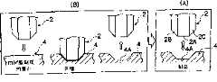
图3是说明由树脂制成的磨石制备的成形磨石对玻璃基片的外周边进行抛光的示意图。Fig. 3 is a schematic diagram illustrating polishing of the outer periphery of a glass substrate by a shaped grindstone prepared from a resin-made grindstone.
图4是说明由树脂制成的磨石制备的棍形磨石对玻璃基片的外周边进行抛光的是以图。Fig. 4 is a diagram illustrating polishing of the outer periphery of a glass substrate by a stick-shaped whetstone prepared from a whetstone made of resin.
在附图中,附图标记1表示转台,2表示玻璃基片,3表示用来研磨外边缘表面的磨石,4表示由树脂制成的磨石,5表示用来研磨内边缘表面的磨石,6表示用来抛光内边缘表面的磨石,7表示固定器,10表示用来对玻璃基片的边缘表面进行抛光的设备,30表示棒形磨石,A表示第一操作台,B表示第二操作台,C表示第三操作台。In the drawings,
下面,参照附图详细说明本发明对用于磁记录介质的玻璃基片的边缘表面进行抛光的设备以及制造所述玻璃基片的方法。Hereinafter, an apparatus for polishing an edge surface of a glass substrate for a magnetic recording medium and a method for manufacturing the same according to the present invention will be described in detail with reference to the accompanying drawings.
具体实施方式Detailed ways
图1是对用于磁记录介质的玻璃基片的边缘表面进行抛光的设备10的一个实施方式的结构示意图。用这种设备10来抛光边缘表面的加工系统是设计成能在不同位置同时进行至少一个安装和拆卸玻璃基片的步骤、对玻璃基片的内边缘表面和外边缘表面进行粗研磨的步骤、以及对玻璃基片的内边缘表面和外边缘表面进行抛光的步骤的系统,而要实现这样的设计,该系统包括多个操作台,包括至少一个用来安装和拆卸玻璃基片的第一操作台A、用来对玻璃基片的内边缘表面和外边缘表面进行粗研磨的第二操作台B、以及对玻璃基片的内边缘表面和外边缘表面进行抛光的第三操作台C,以及传送安装在第一操作台A的玻璃基片依次通过上述各操作台的传送机构。此外,将这种加工系统设计成使得在进行抛光持续时间加上在操作台之间一次传送所需的时间内完成一次对一块玻璃基片的边缘表面的研磨和抛光,在上述三个步骤中抛光需要的操作时间最长。FIG. 1 is a schematic block diagram of one embodiment of an
图1所示设备是最简单的三操作台型抛光设备10。用来安装和拆卸玻璃基片的第一操作台A、用来对玻璃基片的内边缘表面和外边缘表面进行粗研磨的第二操作台B、以及对玻璃基片的内边缘表面和外边缘表面进行抛光的第三操作台C,以相等间隔(360°/n,n是操作台数,在上述情况,间隔为120°)排列在转台1上。The equipment shown in FIG. 1 is the simplest three-
要加工的玻璃基片由三个相隔120°设置在该转台1上的玻璃基片固定器7旋转支撑。转台1上有旋转驱动机构,三个玻璃基片固定器7,7和7被逐步推到分别对应于第一操作台A、第二操作台B和第三操作台C的位置。对逐步推进设定的时间为上述抛光所需时间加上操作台之间传送一次所需的时间。首先,在第一操作台A,进行抛光后玻璃基片的拆卸和未抛光的玻璃基片的安装;在第二操作台B,对玻璃基片的内边缘表面和外边缘表面进行研磨;在第三操作台C,对玻璃基片的内边缘表面和外边缘表面进行抛光,且以平行的方式同时进行。研磨和抛光可以在不同的操作台进行,并且按照图2所示,分开制备研磨石,即,用来研磨外边缘表面的磨石3、用来抛光外边缘表面的磨石4、用来研磨内边缘表面的磨石和用来抛光内边缘表面的磨石6。此实施方式中,用来抛光外边缘表面的磨石4和用来抛光内边缘表面的磨石6是本发明的由树脂制成的磨石,因此,用来抛光外边缘表面的磨石4是指由树脂制成的磨石4,而用来抛光内边缘表面的磨石6是指由树脂制成的磨石6。优选使用例如通过将金刚石磨粒混入氨基甲酸酯树脂或脲树脂制成的磨石作为由树脂制成的磨石。The glass substrate to be processed is rotatably supported by three
玻璃基片2由转台1上的盘式固定器7旋转支撑,并按照操作台A、B和C的次序依次传送。在第二操作台B和第三操作台C,使玻璃基片2的内边缘表面和外边缘表面与分别进行研磨的磨石和分别进行抛光的磨石接触,进行研磨和抛光,如图2所示。在操作台B和C上分别有用来研磨外边缘表面的磨石3和由树脂制成的磨石4,这些磨石可沿转台1的径向移动,使得在转台1上旋转运动时,它们向外退出,不与玻璃基片2接触,而在加工时,它们向内移动,与玻璃基片2接触。可分别应用伺服电动机气缸作为磨石3和4各自的运动机构,使得在研磨时可以自由调节磨石的移动速度,并在抛光时,通过由所述汽缸提供的恒定气压达到恒压加工。The
此外,在操作台B和C分别有用来研磨内边缘表面的磨石5和由树脂制成的磨石6,这些磨石在与转台1的平面的垂直方向上移动,使得在转台1运动时,它们退出到不妨碍转台1旋转的位置,而在转台1的停止状态,用来研磨内边缘表面的磨石5和树脂制成的磨石6运动,使它们位于玻璃基片2的圆孔,所述玻璃基片2由玻璃基片固定器7支撑。在加工时,磨石5和磨石6沿转台1的径向移动,使得它们与玻璃基片2的内边缘表面接触。图2所示的状态是正在进行加工时的状态,用来加工外边缘表面的磨石3或4按图中箭头X所示的方向移动,在转台1的旋转推动下从所示位置后退,与玻璃基片2的外边缘表面接触;用来加工内边缘表面的磨石5或6首先在箭头Z所示的方向移动,以位于玻璃基片2的圆孔中,然后按箭头X所示方向移动,以与玻璃基片2的内边缘表面接触。用来加工外边缘表面的磨石3或4和用来加工内边缘表面的磨石5或6都以高速旋转,在接触中研磨或抛光玻璃基片2的外边缘表面和内边缘表面。通过在操作台B或C的玻璃基片固定器7的旋转驱动机构,玻璃基片2以低速旋转驱动,使得能在360°的整个边缘表面进行加工。可以平行的方式,在操作台B和C分别同时进行这种外边缘表面加工和内边缘表面加工。In addition, there are grinding stones 5 for grinding the inner edge surface and grinding stones 6 made of resin on the operating tables B and C, respectively, and these grinding stones move in a direction perpendicular to the plane of the
操作台B和C因为使用的磨石分别是用来研磨和用来抛光的而不同,但是它们都提供了类似的驱动机构。此外,在第一操作台A拆卸加工后的玻璃基片2以及安装未加工的玻璃基片2都可以手工操作,但是从自动化效率考虑,在此实施方式中提供了自动机械装置。Stations B and C differ in that the stones used are for grinding and polishing, respectively, but both provide similar drive mechanisms. In addition, dismounting the processed
在上述结构中,在第一操作台A,由自动机械机构来拆卸已加工的玻璃基片2,然后将未加工的玻璃基片2传送到玻璃基片固定器7。玻璃基片固定器7上有一个真空抽吸机构,通过操作该真空抽吸机构,可牢固地支撑未加工的玻璃基片2。此时,需要通过在操作台B和C上进行研磨和抛光使这样支撑的玻璃基片2精确位于与玻璃基片固定器7的旋转轴同心的位置。这一要求使得内边缘表面和外边缘表面在操作台B和C上进行精确地同心研磨和抛光处理。为此目的,由上述自动机械装置对玻璃基片固定器7上的未加工玻璃基片2传送定位的精度,以及在通过消除在操作台B和C之间进行传送时玻璃基片固定器的改变来保持研磨达到的同心位置状态下进行研磨,变得很重要。In the above structure, at the first operation station A, the processed
在第二操作台B,当通过旋转转台1带来由玻璃基片固定器7支撑的玻璃基片时,以低速旋转玻璃基片2的旋转机构(未示出)与玻璃基片固定器7之间采用接合关系。这可以由离合机构(未示出)进行,使得在转台1旋转时,解除该接合关系,而当转台停止在操作台位置时,进行所述接合,以通过上述旋转机构来旋转玻璃基片2。以同样方式在第三操作台C上提供上述离合机构,通过离合机构由该旋转机构来旋转玻璃基片2。In the second operation station B, when the glass substrate supported by the
在上述实施方式中,所示转台1为传输机构,以将玻璃基片2依次传送通过各操作台A、B和C。但是,对该传输机构并没有限制,只要是这样的机构,即,用于在各操作台A、B和C之间进行传输的装置能同时彼此驱动,将被传送的玻璃基片2返回到初始安装位置。可以使用合适的传输器。In the above embodiments, the
在此实施方式的抛光设备10中,在用于对玻璃基片2的外边缘表面和内边缘表面进行抛光的步骤中,采用由树脂制成的磨石4和6进行机械抛光的方法。这基于以下观点。In the polishing
在专利文献1揭示的抛光设备中,阻碍产率提高的原因是使用一种用于高精度抛光的磨料的化学抛光设备,不能容易地减少在玻璃基片的加工边界中的改变的原因是采用了批处理。In the polishing apparatus disclosed in
在专利文献1中,对外边缘表面进行抛光,达到算术平均粗糙度(Ra)约为10nm的高精度水平。但是,已经发现,当使用玻璃基片制造硬盘时,如果玻璃基片的内周边缘表面和外周边缘表面的算术平均粗糙度(Ra)最大为100nm,则实际上不存在如形成粉尘的问题。还发现,在这种粗糙度下,使用由硬度小于玻璃基片的树脂(如脲树脂或氨基甲酸酯树脂)制成的磨石,并适当地选择用于树脂磨石的磨粒材料(如金刚石磨粒)、磨粒粒度、磨粒密度、磨粒硬度以及树脂规格等,能够以高产率进行机械抛光,使得抛光处理后的算术平均粗糙度(Ra)达到30-100nm。In
此外,已经发现,由于能够进行机械抛光,可采用片处理来提高产率,同时消除层叠抛光引起的玻璃基片的加工边界的改变,以及单个玻璃基片的尺寸精度的改变,使得这些改变能减少,制成的磨石是由树脂(如脲树脂或氨基甲酸酯树脂)制成的硬度低于玻璃基片2的磨石4。通过适当地选择用于由树脂制成的磨石4的磨粒材料(如金刚石磨粒)、磨粒粒度、磨粒密度、磨粒硬度以及树脂规格等,能完成抛光,使得抛光处理后的算术平均粗糙度(Ra)达到30-100nm。In addition, it has been found that wafer processing can be employed to increase yield due to the ability to perform mechanical polishing while eliminating changes in the processing boundaries of glass substrates caused by stack polishing, as well as changes in the dimensional accuracy of individual glass substrates, so that these changes can Reduced, the prepared grindstone is a
由树脂制成的磨石4较好是具有槽4A的成形磨石,成形为在磨石的两个侧面同时抛光玻璃基片2的外边缘表面2A、以及倒角2B和2C,如图3(A)所示。通过采用由这种成形的磨石作为由树脂制成的磨石4,能在磨石的两个侧面同时抛光玻璃基片2的所有外边缘表面2A以及倒角2B和2C,由此进一步提高加工的产率和均匀性。The
此外,采用以下方式能容易地在成形磨石上形成槽4A的形状(磨石形状),即,将要加工的玻璃基片2的周边侧面部分压向由树脂制成的、成形为棒形的磨石4上(其中,未形成槽4A),在抛光过程中施加大于压力的力,如图3(B)所示,由此在由树脂制成的、呈棒形的磨石4的表面形成凹形(转移的),从而容易地形成与玻璃基片2的周边侧面形状相一致的槽4A。In addition, the shape of the
由树脂制成的磨石4并不限于成形磨石,也可以使用图4所示的棍形磨石30。在这种情况下,如图4(A)所示,将该棍形磨石30的表面压向玻璃基片2的外边缘表面2A,且棍形磨石30沿其轴向往复移动,从而对玻璃基片2的外边缘表面2A进行抛光。然后,如图4(B)所示,使该棍形磨石30倾斜,使该棍形磨石30的表面压向玻璃基片2的倒角2B,且棍形磨石30沿其轴向往复移动,从而对玻璃基片2的倒角2B进行抛光。然后,如图4(C)所示,使该棍形磨石30在相对的侧面倾斜,使该棍形磨石30的表面压向玻璃基片2的倒角2C,且棍形磨石30沿其轴向往复移动,从而对玻璃基片2的倒角2C进行抛光。因此,完成对玻璃基片2的抛光步骤。The
2005年4月7日提交的日本专利申请NO.2005-111104的全部内容,包括说明书、权利要求书、附图和摘要在本文中全部引用作为参考。The entire contents of Japanese Patent Application No. 2005-111104 filed on Apr. 7, 2005 including specification, claims, drawings and abstract are incorporated herein by reference in their entirety.
Claims (4)
Applications Claiming Priority (2)
| Application Number | Priority Date | Filing Date | Title |
|---|---|---|---|
| JP2005111104AJP2006294099A (en) | 2005-04-07 | 2005-04-07 | Apparatus for polishing peripheral surface of glass substrate for magnetic recording medium and manufacturing method thereof |
| JP2005111104 | 2005-04-07 |
Publications (1)
| Publication Number | Publication Date |
|---|---|
| CN1843694Atrue CN1843694A (en) | 2006-10-11 |
Family
ID=37062679
Family Applications (1)
| Application Number | Title | Priority Date | Filing Date |
|---|---|---|---|
| CNA2006100737189APendingCN1843694A (en) | 2005-04-07 | 2006-04-06 | Apparatus for polishing edge surface of glass substrate for magnetic recording medium and method for manufacturing glass substrate |
Country Status (3)
| Country | Link |
|---|---|
| US (2) | US20060228997A1 (en) |
| JP (1) | JP2006294099A (en) |
| CN (1) | CN1843694A (en) |
Cited By (1)
| Publication number | Priority date | Publication date | Assignee | Title |
|---|---|---|---|---|
| CN103506910A (en)* | 2012-06-20 | 2014-01-15 | 刘德辉 | Optical low pass filter substrate machining process |
Families Citing this family (17)
| Publication number | Priority date | Publication date | Assignee | Title |
|---|---|---|---|---|
| JP2008024528A (en)* | 2006-07-18 | 2008-02-07 | Asahi Glass Co Ltd | Manufacturing method of glass substrate for magnetic disk |
| JP5281136B2 (en)* | 2006-09-01 | 2013-09-04 | Hoya株式会社 | Glass substrate for magnetic disk and magnetic disk |
| JP5019999B2 (en)* | 2006-09-01 | 2012-09-05 | Hoya株式会社 | Manufacturing method or manufacturing apparatus of glass substrate for magnetic disk, and manufacturing method of magnetic disk |
| JP2008112497A (en)* | 2006-10-30 | 2008-05-15 | Fujitsu Ltd | Disc end face burnishing device and disc end face burnishing method |
| JP4252093B2 (en)* | 2007-01-18 | 2009-04-08 | 昭和電工株式会社 | Disc-shaped substrate grinding method and grinding apparatus |
| JP4748115B2 (en)* | 2007-06-12 | 2011-08-17 | コニカミノルタオプト株式会社 | Glass substrate for magnetic recording medium and magnetic recording medium |
| JP2009035461A (en)* | 2007-08-03 | 2009-02-19 | Asahi Glass Co Ltd | Manufacturing method of glass substrate for magnetic disk |
| JP4860580B2 (en)* | 2007-09-07 | 2012-01-25 | Hoya株式会社 | Magnetic disk substrate and magnetic disk |
| US8722189B2 (en) | 2007-12-18 | 2014-05-13 | Hoya Corporation | Cover glass for mobile terminals, manufacturing method of the same and mobile terminal device |
| KR101397274B1 (en)* | 2008-04-16 | 2014-05-21 | 도탄카코 가부시키가이샤 | Lead wire embedding device and lead wire embedding method |
| US8932510B2 (en) | 2009-08-28 | 2015-01-13 | Corning Incorporated | Methods for laser cutting glass substrates |
| US8946590B2 (en) | 2009-11-30 | 2015-02-03 | Corning Incorporated | Methods for laser scribing and separating glass substrates |
| JP5776491B2 (en)* | 2011-10-24 | 2015-09-09 | 信越化学工業株式会社 | Glass substrate for photomask, reticle or nanoimprint, and method for producing the same |
| US9938180B2 (en)* | 2012-06-05 | 2018-04-10 | Corning Incorporated | Methods of cutting glass using a laser |
| US9610653B2 (en) | 2012-09-21 | 2017-04-04 | Electro Scientific Industries, Inc. | Method and apparatus for separation of workpieces and articles produced thereby |
| CN114388000B (en)* | 2017-08-31 | 2024-01-30 | Hoya株式会社 | Spacer and hard disk drive device |
| CN112157544B (en)* | 2020-09-29 | 2022-01-28 | 维沃移动通信(重庆)有限公司 | Glass manufacturing method, glass and electronic equipment |
Family Cites Families (27)
| Publication number | Priority date | Publication date | Assignee | Title |
|---|---|---|---|---|
| EP0263512B1 (en)* | 1986-10-09 | 1994-06-01 | Asahi Glass Company Ltd. | Glass substrate for a magnetic disc and process for its production |
| JPH05290365A (en)* | 1992-02-12 | 1993-11-05 | Asahi Glass Co Ltd | Glass magnetic disk substrate |
| US5538579A (en)* | 1992-10-08 | 1996-07-23 | Asahi Glass Company Ltd. | Method of processing a plurality of glass plates or the like into a circular shape or a method of perforating a plurality of the same material |
| US5569518A (en)* | 1993-07-07 | 1996-10-29 | Ag Technology Co., Ltd. | Glass substrate for a magnetic disk with roughened edges |
| WO1996030901A1 (en)* | 1995-03-30 | 1996-10-03 | Ag Technology Co., Ltd. | Method of manufacturing glass substrate for magnetic disk |
| GB2299991B (en)* | 1995-04-20 | 1998-09-09 | Ag Technology Corp | Glass substrate for magnetic disk |
| US20010049031A1 (en)* | 1999-03-04 | 2001-12-06 | Christopher H. Bajorek | Glass substrate for magnetic media and method of making the same |
| US6394888B1 (en) | 1999-05-28 | 2002-05-28 | Saint-Gobain Abrasive Technology Company | Abrasive tools for grinding electronic components |
| US6363599B1 (en)* | 1999-08-04 | 2002-04-02 | Komag, Inc. | Method for manufacturing a magnetic disk including a glass substrate |
| US6718612B2 (en)* | 1999-08-04 | 2004-04-13 | Asahi Glass Company, Ltd. | Method for manufacturing a magnetic disk comprising a glass substrate using a protective layer over a glass workpiece |
| US6795274B1 (en)* | 1999-09-07 | 2004-09-21 | Asahi Glass Company, Ltd. | Method for manufacturing a substantially circular substrate by utilizing scribing |
| US6664503B1 (en)* | 1999-09-07 | 2003-12-16 | Asahi Glass Company, Ltd. | Method for manufacturing a magnetic disk |
| US6829910B1 (en)* | 2000-04-25 | 2004-12-14 | Asahi Glass Company, Ltd. | Removal of enclosed glass parts after cutting using heating and cooling techniques |
| US6949485B2 (en)* | 2000-06-01 | 2005-09-27 | Asabi Glass Company, Limited | Glass for substrate and glass substrate |
| WO2001098024A1 (en) | 2000-06-21 | 2001-12-27 | 3M Innovative Properties Company | Abrasive article, apparatus and process for finishing glass or glass-ceramic recording disks |
| JP2002160170A (en) | 2000-11-24 | 2002-06-04 | Tamagawa Seiki Co Ltd | Glass processing whetstone and glass polishing method |
| JP4274708B2 (en)* | 2001-05-14 | 2009-06-10 | Hoya株式会社 | Glass substrate for magnetic recording medium and manufacturing method thereof |
| JP2003016633A (en)* | 2001-06-28 | 2003-01-17 | Asahi Glass Co Ltd | Glass substrate for magnetic disk and manufacturing method thereof |
| US20030134734A1 (en)* | 2001-08-08 | 2003-07-17 | Shiro Nishimoto | Press molding method for glass and manufacturing method for glass substrate using this method |
| JP3933432B2 (en)* | 2001-09-10 | 2007-06-20 | Hoya株式会社 | Glass substrate clamping jig, glass substrate processing method, and glass substrate |
| US6685755B2 (en)* | 2001-11-21 | 2004-02-03 | Saint-Gobain Abrasives Technology Company | Porous abrasive tool and method for making the same |
| JP2003272336A (en)* | 2002-03-18 | 2003-09-26 | Asahi Glass Co Ltd | Glass mounting member for magnetic disk and manufacturing method thereof |
| JP2003272337A (en)* | 2002-03-18 | 2003-09-26 | Asahi Glass Co Ltd | Manufacturing method of glass spacer ring for magnetic disk and spacer ring |
| US6988937B2 (en)* | 2002-04-11 | 2006-01-24 | Saint-Gobain Abrasives Technology Company | Method of roll grinding |
| JP2004142029A (en)* | 2002-10-24 | 2004-05-20 | Noritake Co Ltd | Vitrified grinding wheel |
| SG112980A1 (en)* | 2003-12-19 | 2005-07-28 | Asahi Glass Co Ltd | Glass substrate for magnetic disks and process for its production |
| JP2006099939A (en)* | 2004-08-31 | 2006-04-13 | Asahi Glass Co Ltd | Glass substrate for magnetic disk. |
- 2005
- 2005-04-07JPJP2005111104Apatent/JP2006294099A/ennot_activeWithdrawn
- 2006
- 2006-04-06CNCNA2006100737189Apatent/CN1843694A/enactivePending
- 2006-04-06USUS11/398,653patent/US20060228997A1/ennot_activeAbandoned
- 2009
- 2009-03-02USUS12/396,191patent/US8021212B2/ennot_activeExpired - Fee Related
Cited By (2)
| Publication number | Priority date | Publication date | Assignee | Title |
|---|---|---|---|---|
| CN103506910A (en)* | 2012-06-20 | 2014-01-15 | 刘德辉 | Optical low pass filter substrate machining process |
| CN103506910B (en)* | 2012-06-20 | 2017-09-15 | 山东博达光电有限公司 | Optical low-pass filter substrate processing technology |
Also Published As
| Publication number | Publication date |
|---|---|
| US20060228997A1 (en) | 2006-10-12 |
| US20090227187A1 (en) | 2009-09-10 |
| US8021212B2 (en) | 2011-09-20 |
| JP2006294099A (en) | 2006-10-26 |
Similar Documents
| Publication | Publication Date | Title |
|---|---|---|
| CN1843694A (en) | Apparatus for polishing edge surface of glass substrate for magnetic recording medium and method for manufacturing glass substrate | |
| JP5305214B2 (en) | End face processing method of plate glass | |
| CN1810480B (en) | Method for manufacturing a doughnut-shaped glass substrate | |
| JP4406752B2 (en) | Glass substrate end face processing apparatus and end face processing method | |
| JP5454180B2 (en) | Manufacturing method of glass substrate for magnetic recording medium and glass substrate for magnetic recording medium | |
| WO2008059931A1 (en) | Process for producing glass substrate | |
| US20100247977A1 (en) | Subastrate for a magnetic disk and method of manufacturing the same | |
| CN101224552A (en) | Grinding method and grinding device for disc-shaped substrate | |
| CN111480216A (en) | Substrate processing system, substrate processing method, and computer storage medium | |
| US8317572B2 (en) | Method for manufacturing a glass substrate for a magnetic disc | |
| TW201700709A (en) | Abrasive grindstone | |
| JPH09168953A (en) | Semiconductor wafer edge polishing method and device | |
| CN1254633A (en) | Method for grinding glass substrate | |
| JP6608604B2 (en) | Chamfered substrate and method for manufacturing liquid crystal display device | |
| JP2012143852A (en) | Apparatus for manufacturing glass disc | |
| CN1272669A (en) | Sliding device and method for manufacturing sliding device | |
| US10166652B2 (en) | Substrate polishing device and method thereof | |
| JP6590049B2 (en) | End face processing equipment for plate | |
| JPH0684855A (en) | Cutting-off of substrate as well as method and apparatus for chamfering | |
| JP2013140648A (en) | Manufacturing method of glass substrate for magnetic disk and glass substrate for magnetic disk | |
| CN1196993A (en) | Magnetic substrate semi-products, its making method and grinding processing appts. | |
| JP2016190284A (en) | Manufacturing method of chamfered baseboard and chamfering device used in the same | |
| CN107004431A (en) | Manufacturing method of substrate for magnetic disk and grindstone for grinding | |
| JP2022045211A (en) | Processing method for notch of waver and grindstone | |
| JP6609847B2 (en) | End face processing equipment for plate |
Legal Events
| Date | Code | Title | Description |
|---|---|---|---|
| C06 | Publication | ||
| PB01 | Publication | ||
| C10 | Entry into substantive examination | ||
| SE01 | Entry into force of request for substantive examination | ||
| C02 | Deemed withdrawal of patent application after publication (patent law 2001) | ||
| WD01 | Invention patent application deemed withdrawn after publication |